EP2379279B1 - Reciprocating skate blade sharpener - Google Patents
Reciprocating skate blade sharpener Download PDFInfo
- Publication number
- EP2379279B1 EP2379279B1 EP09832796.8A EP09832796A EP2379279B1 EP 2379279 B1 EP2379279 B1 EP 2379279B1 EP 09832796 A EP09832796 A EP 09832796A EP 2379279 B1 EP2379279 B1 EP 2379279B1
- Authority
- EP
- European Patent Office
- Prior art keywords
- sharpening
- sharpener
- skate blade
- side face
- base
- Prior art date
- Legal status (The legal status is an assumption and is not a legal conclusion. Google has not performed a legal analysis and makes no representation as to the accuracy of the status listed.)
- Active
Links
Images












Classifications
-
- B—PERFORMING OPERATIONS; TRANSPORTING
- B24—GRINDING; POLISHING
- B24B—MACHINES, DEVICES, OR PROCESSES FOR GRINDING OR POLISHING; DRESSING OR CONDITIONING OF ABRADING SURFACES; FEEDING OF GRINDING, POLISHING, OR LAPPING AGENTS
- B24B3/00—Sharpening cutting edges, e.g. of tools; Accessories therefor, e.g. for holding the tools
- B24B3/003—Sharpening cutting edges, e.g. of tools; Accessories therefor, e.g. for holding the tools for skate blades
-
- A—HUMAN NECESSITIES
- A63—SPORTS; GAMES; AMUSEMENTS
- A63C—SKATES; SKIS; ROLLER SKATES; DESIGN OR LAYOUT OF COURTS, RINKS OR THE LIKE
- A63C11/00—Accessories for skiing or snowboarding
- A63C11/04—Accessories for skiing or snowboarding for treating skis or snowboards
- A63C11/06—Edge-sharpeners
-
- A—HUMAN NECESSITIES
- A63—SPORTS; GAMES; AMUSEMENTS
- A63C—SKATES; SKIS; ROLLER SKATES; DESIGN OR LAYOUT OF COURTS, RINKS OR THE LIKE
- A63C3/00—Accessories for skates
- A63C3/10—Auxiliary devices for sharpening blades
Definitions
- the present invention relates to sharpeners and more particularly to portable sharpeners for snow/ice travel members such as ice skates, skis and snowboards.
- WO 97/05988 A1 discloses a portable electric skate sharpener having a motor body made to accept grinding, honing and conditioning heads to fit various blade types and to perform various finishing operations upon the blade.
- the appropriate head is fitted to the motor, the head fitted over the skate blade with the provided slot clamps, and the motor switched on. The head is passed up and down the blade until the desired degree of finish is achieved.
- the invention is directed to a sharpener according to claim 1 and to embodiments as defined by the dependent claims.
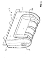
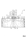
- FIG. 1a shows a sharpener 10, in accordance with an embodiment of the present invention.
- the sharpener 10 may be used to sharpen a skate blade 12 of a skate (not shown).
- the sharpener 10 may also be used as a blade sharpness maintenance device, whereby it is used on the skate blade 12 prior to each trip a skater makes onto an ice surface.
- the skate blade 12 includes a first side face 78, a second side face 80, an edge face 68, a first corner edge 32 and a second corner edge 34. For ease of illustration, only the lower portion of the skate blade 12 is shown in the figures.
- the skate blade 12 has a thickness T.
- the sharpener 10 includes a body 14, a skate blade orienting structure 16, a first corner edge sharpening structure 17a for sharpening the first corner edge 32 ( Figure 6b ), a second corner edge sharpening structure 17b for sharpening the second corner edge 34 ( Figure 6b ), and a drive mechanism 22 ( Figure 2 ) for driving movement of the first and second corner edge sharpening structures 17a and 17b relative to the body 14.
- the body 14 may be a two-piece assembly (see Figure 1a ), and may be made from a suitable material such as a molded plastic.
- the skate blade orienting structure 16 which in a simple incarnation is a slot 24 in the body 14, is configured to orient the skate blade 12 ( Figure 1a ) along a selected direction line 23 relative to the first and second corner edge sharpening structures 17a and 17b.
- the direction line 23 may be referred to as the longitudinal direction line 23, since the orienting structure 16 sets the orientation of the longitudinal axis of the skate blade 12.
- a lateral direction line, shown at 61, is transverse to the longitudinal direction line 23.
- the skate blade orienting structure 16 also centers the skate blade 12 laterally on the first and second corner edge sharpening structures 17a and 17b.
- the skate blade orienting structure 16 may have any suitable structure.
- the slot 24 has a first slot side wall 26, a second slot side wall 28 and a slot floor 30.
- the first and second slot side walls 26 and 28 are engageable with the first and second side faces 78 and 80 of the skate blade 12.
- the slot floor 30 sets the position (the height specifically) of the edge face 68 and may be referred to as an edge face positioning surface 30. Due to the concavity of the edge face 68, the slot floor 30 may engage the first and second corner edges 32 and 34 and be spaced from the edge face 68 itself.
- first and second corner edge sharpening structures 17a and 17b are positioned on a sharpening base 40.
- the first corner edge sharpening structure 17a includes a first edge face sharpening surface 18 and a first side face sharpening surface 19.
- the second corner edge sharpening structure 17b includes a second edge face sharpening surface 20 and a second side face sharpening surface 21.
- the first edge face sharpening surface 18 is positioned for sharpening the edge face 68 proximate the first corner edge 32, and the first side face sharpening surface 19 is positioned for sharpening the first side face 78 proximate the first corner edge 32.
- the second edge face sharpening surface 20 is positioned for sharpening the edge face 68 proximate the second corner edge 34, and the second side face sharpening surface 21 is positioned for sharpening the second side face 80 proximate the second corner edge 34.
- the first and second edge face sharpening surfaces 18 and 20 are angled downwardly in a laterally outward direction (ie. in a lateral direction away from each other). In this way, they maintain the concavity of the edge face 68 of the skate blade 12.
- first and second side face sharpening surfaces 19 and 21 may be sloped laterally towards each other slightly (eg. by one degree from vertical) and the lower portions of these sharpening surfaces 19 and 21 are inboard of the slot side walls 26 and 28, so that they are ensured of engagement with the first and second side walls. Note that some of the relative sizes of selected elements shown in Figures 6a and 6b may be exaggerated for visual clarity, however, these figures are not to be interpreted as being to scale.
- the sharpening surfaces 18, 19, 20 and 21 may be made in any suitable way.
- they may be covered with an abrasive material such as diamond, or Cubic Boron Nitride (CBN).
- first and second edge face sharpening surfaces 18 and 20 may be surfaces on separate first and second bosses 36 and 38 respectively on the sharpening base 40. It is alternatively possible for the first and second edge face sharpening surfaces 18 and 20 to be portions of a surface of a single large boss or similar feature, as shown at 41 in Figure 9 .
- the embodiment shown in Figure 9 permits the sharpener 10 to be used to sharpen a skate blade 12 outright, since it is capable of forming the entire concave surface of the edge face 68 of the skate blade 12, whereas the embodiment shown in Figure 2 with two smaller, separate bosses 36 and 38 are preferably used to maintain the sharpness of the corner edges 32 and 34.
- the first and second side face sharpening surfaces 19 and 21 may be on first and second side face sharpening structures 70 and 74 respectively, which are also on the sharpening base 40.
- the sharpening base 40 may be made removable from the rest of the sharpener 10 so that it can be replaced with a new sharpening base 40 when it wears out and is no longer effective.
- the sharpening base 40 may be considered to be a disposable part of the sharpener 10, and the rest of the sharpener 10 may be considered to be non-disposable, at least in some embodiments.
- the sharpening base 40 may removably lock into a base support 42, by any suitable connecting structure.
- the sharpening base 40 may include a first and second apertures 44 and 46, which receive first and second pins 48 and 50 on the base support 42.
- the first aperture 44 may be circular and the first pin 48 may be circular.
- the second aperture 46 is a keyhole slot, and the second pin 50 is a T-pin (ie. it is T-shaped).
- the sharpening base 40 is then rotated to lock the T-pin 50 into the narrower part of the keyhole slot 46.
- the first aperture 44 to be a keyhole slot and for the first pin 48 to be T-shaped.
- the sharpening base 40 is relatively small and may be made from a suitable plastic that is easily moldable and is relatively inexpensive or from an inexpensive grade of steel that can be stamped or from a powdered metal. Additionally, the sharpening base 40 can be, as shown, relatively easily removable from and installable onto the base support 42.
- the base support 42 is driven by the drive mechanism 22.
- the drive mechanism 22 includes a motor 52 with an output shaft 54 which has an offset drive member 56 thereon that is offset from the output shaft axis, shown at Am.
- the drive mechanism 22 further includes a first driven member 58 and a second driven member 60.
- the first driven member 58 is slidably mounted to the second driven member 60.
- the second driven member 60 is configured to restrict the first driven member 58 to only have freedom of movement approximately along the transverse direction line 61.
- the second driven member 60 is slidably mounted on a carriage 62 and is restricted by the carriage 62 to only have freedom of movement approximately along sliding movement approximately along the longitudinal direction line 23.
- Rotation of the motor output shaft 54 causes the offset drive member 56 to 'orbit' about the motor output shaft axis Am.
- This orbiting path causes the first driven member 58 to move in the orbiting (ie. circular path).
- This circular path results in transverse displacement and longitudinal displacement.
- the transverse displacement of the first driven member 58 does not drive any transverse movement of the second driven member.
- the longitudinal displacement of the first driven member 58 drives longitudinal displacement of the second driven member 60.
- the second driven member 60 reciprocates along the longitudinal direction line 23.
- the second driven member 60 supports the base support 42.
- operation of the drive mechanism 22 generates reciprocation of the base support 42, and therefore the sharpening surfaces 18, 19, 20 and 21 along a reciprocation path along the longitudinal direction line 23.
- the second driven member 60 has two slide bars 64 thereon, which hold the base support 42 and support sliding of the base support 42 along a third direction line 65 that is transverse to the edge face positioning surface 30.
- the third direction line 65 is vertical when the sharpener 10 is oriented as shown in Figure 2 .
- a biasing member 66 shown in Figure 4 , biases the base support 42 towards the edge face positioning surface 30 and therefore urges the sharpening surfaces 18 and 20 to engage the edge face 68 ( Figure 3 ), of the skate blade 12 when the skate blade 12 is positioned on the edge face positioning surface 30.
- the biasing member 66 ( Figure 4 ) may be referred to as a sharpening surface engagement biasing member, since it biases the sharpening surfaces 18, 19, 20 and 21 towards engagement with the skate blade 12, or alternatively a sharpening structure engagement biasing member since it biases the sharpening structures 17a and 17b towards engagement with the snow/ice travel member, which may be, for example, the skate blade 12.
- the sharpening surface engagement biasing member 66 may be any suitable type of biasing member, such as a compression spring.
- the skate blade 12 is not shown in engagement with the edge face positioning surface 30.
- the sharpening surfaces 18, 19, 20 and 21 are urged by the sharpening surface engagement biasing member 66 to a rest position that is past the edge face positioning surface 30.
- the sharpening surface engagement biasing member 66 is compressed by a certain amount, and therefore urges the sharpening surfaces 18, 19, 20 and 21 into engagement with the skate blade 12 with a selected force, regardless of how hard a user pushes the skate blade 12 into the slot 24. In this way, even when the force of engagement between the skate blade 12 and the slot 24 varies, the force that is exerted between the sharpening heads 18 and 20 and the skate blade 12 remains consistent.
- first and second edge face sharpening surfaces 18 and 20 are spaced apart by a first lateral spacing DL1.
- the first and second side face sharpening surfaces 19 and 21 are spaced apart by a second lateral spacing DL2, which is less than the lateral spacing DL1.
- the size of the slot 24 (only part of which is shown in Figure 5 since a portion of the body 14 has been omitted), and the relative positions of the sharpening surfaces 18, 19, 20 and 21 (which determine the lateral spacings DL1 and DL2) determine the thickness T ( Figure 3 ) of skate blade 12 that can be sharpened.
- the sharpener 10 may advantageously be configured to accommodate a range of thicknesses T of skate blades 12.
- the sharpening base 40 may be rotated through a range of positions, which changes the lateral spacings DL1 and DL2, as shown in the two exemplary positions of the sharpening base 40 in Figures 7a and 7b .
- the sharpening base 40 may be rotatable to adjust the relative positions of the sharpening surfaces 18, 19, 20 and 21 so as to control the thickness of skate blade 12 that can be sharpened.
- the carriage 62 may be movable relative to the body 14.
- a first carriage biasing member 82, and a second carriage biasing member 84, both shown in Figure 5 bias the carriage 62 clockwise in the view shown in Figure 5 , which biases the sharpening surfaces 18, 19, 20 and 21 towards having reduced lateral spacings DL 1 and DL2.
- the carriage biasing members 82 and 84 therefore drive the first and second side face sharpening surfaces 19 and 21 into engagement with the skate blade 12, at least over a working range of adjustability.
- the sharpening base 40 is rotated in a direction (counterclockwise in the view shown in Figure 5 ) that increases the spacings DL1 and DL2.
- the carriage 62 is rotated against the biasing of the carriage biasing members 82 and 84.
- the carriage biasing members 82 and 84 may be referred to as side face sharpening surface engagement biasing members 82 and 84 since they bias the side face sharpening surfaces 19 and 21 into engagement with the skate blade 12.
- the sharpening surfaces 18, 19, 20 and 21 are preferably solid revolutions of profiles at least partway about their own individual axes. It is optionally possible, however, for the sharpening surfaces 18 and 20 to have shapes that are not solid revolutions.
- the rotation of the carriage 62 when accommodating thicker skate blades 12 means that the carriage 62 may not initially be oriented strictly longitudinally (ie. precisely along the longitudinal direction line 23) when a thicker skate blade 12 is inserted into the slot 24. Notwithstanding the misalignment of the carriage 62 with respect to the longitudinal direction line 23, the skate blade 12 itself prevents the movement of the sharpening base 40 and therefore the second driven member 60 along a line other than the longitudinal direction line 23. To permit such movement, the biasing members 82 and 84 permit the carriage 62 to float sufficiently during the reciprocation of the sharpening base 40 and second driven member 60.
- the sharpening base 40 could be rotatable relative to the second driven member 60 to accommodate skate blades 12 of different thicknesses.
- the carriage 62 could be fixedly aligned longitudinally within the body 14 (such as the embodiment shown in Figure 19 ) and the biasing members 82 and 84 could be omitted.
- the sharpener 10 may further include a plurality of shoes 96 ( Figure 8 ) that are each sized to hold a different thickness of skate blade 12.
- Each shoe 96 would fit on the body 14, and would have an open-bottom slot 98 therein, which has first and second slot side walls 100a and 100b which define an opening for a skate blade 12 having a selected thickness T and which together form a skate blade orienting structure.
- the slot 98 be open-bottomed, the skate blade 12 is permitted to engage the edge face positioning surface 30 so that the same force is applied by the sharpening surfaces 18, 19, 20 and 21 on the skate blade 12 whether or not a shoe 96 is used.
- a kit of parts 102 may be provided that includes the sharpener 10 and at least one shoe 96 having a slot width that is different from the slot width of the slot 24 (and preferably a plurality of interchangeable shoes 96 of different slot widths) to accommodate a variety of skate blade thicknesses.
- the at least one shoe 96 and the sharpener 10 together include a plurality of skate blade orienting structures (eg. the slots 24 and 98) wherein each skate blade orienting structure is configured for orienting a skate blade having a unique width along a longitudinal direction line and for centering the skate blade 12 laterally with respect to the edge face sharpening surfaces 18 and 20.
- the sharpener 10 itself need not include a slot that constitutes a skate blade orienting structure.
- all the skate blade orienting structures could be provided by slots 98 in the plurality of shoes 96.
- first and second side face sharpening surfaces 19 and 21 are not provided. It is also possible to provide an embodiment of the invention wherein the first and second side face sharpening structures 70 and 74 with the sharpening surfaces 19 and 21 thereon are replaced with first and second side face guide structures, with first and second side face guide surfaces that guide the bottom-most portion of the skate blade 12 to ensure that it is centered on the first and second edge face sharpening surfaces 18 and 20.
- the first and second side face guide surfaces may be similar to the first and second side face sharpening surfaces 19 and 21, except that they would not contain abrasive material.
- first and second side face sharpening surfaces 19 and 21 are provided, and therefore contain abrasive material, they nonetheless also act as first and second side face guide surfaces to center the skate blade 12 on the first and second edge face sharpening surfaces 18 and 20.
- the motor 52 may be powered by any suitable source, such as by one or more batteries 92.
- the sharpener 10 may include a connector (eg. a plug) for plugging into an A/C source, such as a wall outlet (not shown).
- a switch shown at 94 in Figure 1a may be provided to turn the skate sharpener 10 on.
- the switch 94 may need to be depressed by the user at all times the sharpener 10 is to be operated, such that once the user lets go of the switch 94, the switch 94 is urged to an 'off' position preventing current flow to the motor 52.
- a user turns on the sharpener 10, and may hold the gripping surface shown at 106 ( Figure 1a ) on the body 14, and passes the sharpener 10 along the edge face 68 of the skate blade 12 so that the sharpening surfaces 18 and 20 are able to reciprocate along their reciprocation path (which may be just a few millimeters in at least some embodiments), along the entire length of the edge face 68 of the skate blade 12.
- FIG. 10 shows the sharpener 10 with an optional item engagement sensor 108 that is configured to detect whether the user has inserted a skate blade 12 into the sharpener 10 for sharpening.
- the item engagement sensor 108 may have any suitable structure.
- the item engagement sensor 108 may be a switch 110 that is closed by a projection 112 on the base support 42 when the skate blade 12 is engaged with the sharpening structures 17a and 17b and moves the sharpening base 40 downwards against the force of the sharpening surface engagement biasing member 66.
- the switch 110 may communicate with a controller 114 that controls the operation of the motor 52.
- the controller 114 may prevent operation of the motor 52 if the switch 110 is open (indicating that a skate blade 12 is not present), so as to conserve energy in the batteries 92. Therefore, if the button 94 is in the 'on' position (eg. it is depressed by a user), the controller 114 may disconnect power to the motor 52 in the event that the switch 110 is open. Furthermore, the controller 114 may send power to the motor 52 if the button 94 is 'on' and the switch 110 is closed (indicating that a skate blade 12 ( Figure 10 ) is engaged and seated fully on the sharpening base 40).
- the switch 94 may be omitted.
- the controller 114 may send power to the motor 52 automatically if the switch 110 is closed, and may automatically disconnect power to the motor 52 if the switch 110 is opened.
- the operation of the motor 52 may be automated.
- FIG. 12 shows the sharpener 10 with two item engagement sensors 116.
- the item engagement sensors 116 may be positioned in the slot 24 ahead of and behind the sharpening base 40.
- Each item engagement sensor 116 may include a button 117 that is slidable in a button-receiving aperture 118 in the slot floor 30, a biasing member 120 and a switch 122.
- the biasing member 120 urges the button 117 to project from the slot floor 30. Placement of the skate blade 12 on the slot floor 30 depresses the buttons 117 causing closure of the switches 122. Closure of both switches 122 signals a controller 124 ( Figure 13 ) to permit operation of the motor 52.
- the controller 124 may disconnect power to the motor 52 if one or both of the switches 122 is open, and may optionally send power to the motor 52 if both switches 122 are closed and the button 94 is in the 'on' position. Alternatively, the controller 124 may automatically control the stopping and starting of the motor 52 based on whether both switches 122 are closed, such that the button 94 may be omitted.
- Figure 14 shows the sharpener 10 with an optional item imperfection sensor 126 which can detect imperfections in the skate blade 12 that require smoothing out.
- imperfections as noted above may occur, for example, as a result of blade-to-blade engagement with skate blades 12 from other skaters. Such events can occur, for example, during a game of ice hockey.
- the item imperfection sensor 126 may have any suitable structure.
- the item imperfection sensor 126 may be a capacitive sensor, whose capacitance changes upon exposure to an imperfection (eg. a nick) in the skate blade 12, relative to the capacitance sensed along smooth (ie. unnicked) portions of the skate blade 12.
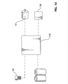
- the item imperfection sensor 126 may send a corresponding signal to a controller 128 ( Figure 15 ).
- the controller 128 may optionally notify a user that an imperfection was encountered, thereby prompting the user to send power to operate the motor 52, eg. by depressing the button 94.
- the notification to the user may be achieved in any suitable way.
- the controller 128 may illuminate an indicator light (eg. an LED), or may generate an audible sound, or both, when an imperfection is encountered.
- the controller 128 could automatically send power to operate the motor 52 upon encountering an imperfection in the skate blade 12, instead of, or in addition to notifying the user of the presence of the imperfection by way of audible or visible indicating means.
- the controller 128 could automatically send power to operate the motor 52 upon encountering an imperfection in the skate blade 12, instead of, or in addition to notifying the user of the presence of the imperfection by way of audible or visible indicating means.
- item imperfection sensor 126 it may be desirable to provide one proximate each corner edge 32 and 34 of the skate blade 12. It will be noted that in embodiments wherein the sensor 126 is provided only on one side of the sharpening base 40, the initiation of the motor 52 by the controller 94 will sharpen the imperfection only if the skate blade 12 and sharpener are being moved relative to each other in the directions shown by the direction arrows 127.
- the sharpening base 40 will not reciprocate along the imperfection.
- the sharpener 10 may optionally have one or more item engagement sensors for sensing the presence of a skate blade 12 and also one or more item imperfection sensors 126.
- the controller would operate the motor 52 if all of the one or more item engagement sensors indicate that a skate blade 12 is engaged properly in the slot 24 and if any item imperfection sensor 126 indicated that an imperfection was encountered. If any item engagement sensor did not signal the presence of a skate blade 12 the controller may stop the motor 52. If no item imperfection sensors 126 signal that an imperfection is encountered, the controller may stop the motor 52.
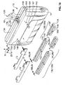
- FIG 16 shows a kit of parts 129 including the sharpener 10 and a plurality of optional shoes, shown generally at 130 and individually at 130a and 130b (it will be understood that more than two shoes 130 could optionally be provided).
- Each shoe 130 contains a slot 24 having a unique width W for accommodating skate blades 12 having different thicknesses T.
- the shoe 130a has a slot 24a having a width Wa
- the shoe 130b has a slot 24b having a width Wb.
- Each shoe 130 may be made up of a first shoe portion 132 and a second shoe portion 134.
- the first shoe portion 132 slides into a first shoe receiving slot 136 that is on a first side of the sharpening base 40.
- the second shoe portion 134 slides into a second shoe receiving slot 138 that is on a second side of the sharpening base 40.
- the first and second shoe portions 132 and 134 together define the slot 24 for receiving a skate blade 12.
- first and second shoe portions 132 and 134 may be provided to hold the first and second shoe portions 132 and 134 in place on the body 14 of the sharpener 10.
- first shoe portion 132 may have flanges 140 and 142, which are received in flange receiving slot regions 144 and 146 ( Figure 16a ). The engagement of the first shoe portion 132 and the first shoe receiving slot 136 prevents movement of the first shoe portion transversely (ie. along the transverse direction line 61) and vertically (ie. along the third direction line 65).
- a first locking pin 148 may be provided, which passes through a first locking pin pass-through aperture 150 in the body 14 of the sharpener 10 and which passes into a first locking pin receiving aperture 152 in the first shoe portion 132, thereby preventing movement of the first shoe portion 132 longitudinally (ie. along the longitudinal direction line 23).
- the first locking pin 148 may have a mechanism for inhibiting the pin 148 from working its way out of the apertures 150 and 152 during use.
- the first locking pin 148 may have a peripheral ball detent 153 thereon that engages a groove (not shown) in the first locking pin receiving aperture 152.
- the second shoe portion 134 may have flanges 154 and 156, which are received in flange receiving slot regions 158 and 160 to prevent movement of the second shoe portion 134 transversely (ie. along the transverse direction line 61) and vertically (ie. along the third direction line 65).
- a second locking pin 162 may be provided, which passes through a second locking pin pass-through aperture 164 in the body 14 of the sharpener 10 and which passes into a second locking pin receiving aperture 166 in the second shoe portion 134, thereby preventing movement of the second shoe portion 134 longitudinally (ie. along the longitudinal direction line 23).
- the second locking pin 162 may have a mechanism for inhibiting the pin 162 from working its way out of the apertures 164 and 166 during use.
- the second locking pin 162 may have a peripheral ball detent 167 thereon that engages a groove (not shown) in the second locking pin receiving aperture 166.
- first and second shoe portions 132 and 134 are positioned to hold the skate blade 12 while providing clearance for the reciprocation of the sharpening base 40.
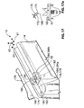
- Figure 17 shows the sharpener 10 configured for sharpening a corner edge 168 of a snow travel member 170, such as a ski or a snowboard.
- the corner edge 168 represents the junction of a side face 172 and a bottom face 174 of the snow travel member 170.
- the sharpener 10 shown in Figure 17 is configured to sharpen one corner edge 168 at a time. As a result, the size of the sharpener 10 shown in Figure 17 may be kept small, thereby keeping it portable.
- the orienting structure 16 for the sharpener 10 shown in Figure 17 may be, for example, a channel 178 in the body 14, for orienting the snow travel member 170 with respect to the sharpener 10.
- the channel 178 may have any suitable shape, such as a V-shape having an internal angle of about 90 degrees.
- the channel 178 has a bottom face receiving wall 180 and a side face receiving wall 182, for receiving the bottom face 174 ( Figure 17a ) and side face 172 of the snow travel member 170.
- the sharpener 10 shown in Figure 17 includes a sharpening base 183 instead of the sharpening base 40 ( Figure 2 ).
- the sharpening base 183 may, as shown in Figure 17 , has mounted thereon a sharpening structure comprising two bottom face sharpening surfaces 184 (shown individually at 184a and 184b) and a side face sharpening surface 186, which are configured to form a V-shape when viewed along the longitudinal direction line 23, and which are configured to sharpen the bottom face 174 ( Figure 17a ) and side face 172 respectively of the snow travel member 170.
- the angles of the bottom face sharpening surfaces 184 and the side face sharpening surface 186 match those of the bottom face receiving wall 180 and side face receiving wall 182 respectively.
- the side face sharpening surface 186 may be positioned longitudinally between the two bottom face sharpening surfaces 184.
- the sharpening base 182 may mount to the base support 42 in the same way as the sharpening base 40 shown in Figure 2 .
- bottom face sharpening surfaces 184 and one side face sharpening surface 186 it is alternatively possible to have some other combination of surfaces, such as, for example, two side face sharpening surfaces 186 and a single bottom face sharpening surface 184.
- one side face sharpening surface 186 and one bottom face sharpening surface 184 may be provided.
- the other elements of the sharpener 10 may be similar as appropriate to the corresponding elements of the sharpener 10 shown in the other figures.
- the sharpener 10 is moved along the length of the snow travel member 170 to permit the reciprocation of the sharpening base 40 to sharpen the corner edge 168.
- the sharpening base 182 need not rotate to a different orientation about the third direction line 65 in order to accommodate skis 170 having different thicknesses and widths.
- structure, such as the biasing members 82 and 84, shown in Figure 5 that permitted the rotation of the sharpening base 40 about the third direction line 65, need not be included in the sharpener 10 shown in Figure 17 .
- the item engagement sensor 108 ( Figure 10 ) and/or the item engagement sensors 116 ( Figure 13 ) and/or the one or more item imperfection sensors 126 ( Figure 14 ) described above to be incorporated into the sharpener 10 shown in Figure 17 for use with the snow travel member 170.
- a shoe 188 may be provided which, in conjunction with the sharpening base 182, would permit the sharpener 10 shown in Figure 17 to sharpen a snow travel member 170, thus providing the sharpener 10 with the capability to sharpen ice skates, skis and snowboards.
- the shoe 188 ( Figure 18 ) includes a first shoe portion 190 and a second shoe portion 192, which can be inserted into the first and second shoe receiving slots 136 and 138 respectively of the sharpener 10 shown in Figure 16 .
- the first and second shoe portions 190 and 192 may have generally V-shaped channels, shown at 194 and 196 respectively, for holding the bottom face 174 and side face 172 ( Figure 17a ) of the snow travel member 170.
- the sharpener 10 has been described in at least some embodiments as being configured to provide sharpening capability to a plurality of thicknesses of skate blade, and to other snow/ice travel members such as snowboards and skis, and may further be portable (with battery and/or A/C power). It is possible that at least some of the features of the sharpener 10 could be applied to a stationary (ie. non-portable) sharpener.
- FIG 19 shows a sharpener 200 in accordance with another embodiment of the present invention.
- the sharpener 200 may be similar to the sharpener 10 ( Figure 1 ), and may include a body 202 (a portion of which is removed to show the components inside it), a skate blade orienting structure 204, a first corner edge sharpening structure 206a ( Figure 20 ) for sharpening the first corner edge 32, a second corner edge sharpening structure 206b for sharpening the second corner edge 34 ( Figure 20 ), and a drive mechanism 208 ( Figure 19 ) for driving the movement of the first and second corner edge sharpening structures 206a and 206b ( Figure 20 ) relative to the body 202 ( Figure 19 ).
- the body 202 may be a two-piece assembly (one of the pieces is not shown, as noted above), and may be made from a suitable material such as a molded plastic.
- the skate blade orienting structure 204 may be a slot 210 in the body 202, similar to the slot 24 in the body 14 in Figure 1 .
- the slot 210 has a first slot side wall 212, a second slot side wall (not shown) and a slot floor 214.
- the first and second slot side walls are engageable with the first and second side faces 78 and 80 of the skate blade 12 ( Figure 20 ).
- the slot floor 214 ( Figure 19 ) sets the position (the height specifically) of the edge face 68 ( Figure 20 ) and may be referred to as an edge face positioning surface 214. Due to the concavity of the edge face 68, the slot floor 214 may engage the first and second corner edges 32 and 34 and be spaced from the edge face 68 itself.
- first and second corner edge sharpening structures 206a and 206b are positioned on a sharpening base 240.
- the first corner edge sharpening structure 206a includes a first edge face sharpening surface 218 and a first side face sharpening surface 219.
- the second corner edge sharpening structure 206b includes a second edge face sharpening surface 220 and a second side face sharpening surface 221.
- the first edge face sharpening surface 218 is positioned for sharpening the edge face 68 proximate the first corner edge 32
- the first side face sharpening surface 219 is positioned for sharpening the first side face 78 proximate the first corner edge 32
- the second edge face sharpening surface 220 is positioned for sharpening the edge face 68 proximate the second corner edge 34
- the second side face sharpening surface 221 is positioned for sharpening the second side face 80 proximate the second corner edge 34.
- the first and second edge face sharpening surfaces 218 and 220 are angled downwardly in a laterally outward direction (ie. in a lateral direction away from each other). In this way, they maintain the concavity of the edge face 68 of the skate blade 12.
- the sharpening base 240 When the sharpening base 240 is viewed along a longitudinal direction of the sharpener 200 the first edge face sharpening surface 218 and the first side face sharpening surface 219 appear to intersect. Similarly, the second edge face sharpening surface 220 and the second side face sharpening surface 221 appear to intersect. This is because the first and second edge face sharpening surfaces 218 and 220 have laterally outer edges that are laterally outboard of the first and second side face sharpening surfaces 219 and 221 respectively. As a result, as the sharpening base 240 is passed along the length of the skate blade 12, the sharpening surfaces 218, 219, 220 and 221 cooperate to provide relatively sharp first and second corner edges 32 and 34.
- the first and second side face sharpening surfaces 219 and 221 may be sloped laterally towards each other slightly and the lower portions of these sharpening surfaces 219 and 221 extend into the slot 212 ( Figure 19 ), so that they are ensured of engagement with the first and second side faces 78 and 80 of the skate blade 12.
- the sharpening surfaces 218, 219, 220 and 221 may be made in any suitable way.
- they may be covered with an abrasive material such as diamond, or Cubic Boron Nitride (CBN).
- first and second edge face sharpening surfaces 218 and 220 may be surfaces on separate first and second tongues 236 and 238 respectively on the sharpening base 240.
- the first and second tongues 236 and 238 are resiliently connected to first and second side walls 242 and 244 of the sharpening base 240, such that the first tongue 236 is connected to the second side wall 244 and the second tongue 238 is connected to the first side wall 242.
- the resilient connections permit the tongues 236 and 238 to flex as necessary to accommodate a skate blade 12 being placed in the slot 212 into engagement with the slot floor 214.
- the resilient connection is provided by cutting and bending the tongues 236 and 238 from the side walls 242 and 244, thereby saving the cost, assembly time, and complexity associated with having separate spring members to provide resiliency. It is nonetheless contemplated that a separate spring member could alternatively be provided for biasing the first and second edge face sharpening surfaces 218 and 220 toward a selected position.
- tongue flexure limit structures 400 and 402 are provided in the first side wall 242 under the first tongue 236 and in the second side wall 244 under the second tongue 238.
- the limit structures 400 and 402 are positioned to permit a selected amount of deflection of the tongues 236 and 238 but prevent deflection that would damage the tongues.
- the first and second side walls 242 and 244 are themselves resiliently joined together by a resilient hinge portion 243 at the their respective bottom ends, shown at 245 and 247.
- the resilient hinge portion 243 permits the first and second side walls 242 and 244 to resiliently spread apart as necessary to accommodate a range of thicknesses of skate blade 12, but biases the first and second walls 242 and 244 back towards a rest position for accommodated narrower skate blades 12.
- Having the integral hinge portion 243 further saves cost, assembly time and complexity that would associated with having a separate spring member resiliently connecting the first and second side walls 242 and 244. It is nonetheless contemplated that some other means for resiliently biasing the first and second side walls 242 and 244 towards the skate blade 12 could alternatively be provided.
- FIG 22a shows a sectional view of the sharpening base 240 mounted in the base support 280.
- the clip portions 246 are connected with the clip receiving features 248, however there is room for the side walls 242 and 244 of the sharpening base 240 to spread apart when receiving a skate blade 12 ( Figure 20 ) therebetween.
- the lower portion of the sharpening base 240 mounts into a mating form in the base support 280 which ensures that the sharpening base 240 sits in an upright position when installed in the base support 280.
- first and second edge face sharpening surfaces 218 and 220 are portions of a surface of a single tongue or similar feature.
- the first and second side face sharpening surfaces 219 and 221 may be on the first and second side walls 242 and 244 respectively, which are also on the sharpening base 240.
- the sharpening base 240 may be made removable from the rest of the sharpener 200 so that it can be replaced with a new sharpening base 240 when it wears out and is no longer effective.
- the sharpening base 240 may be considered to be a disposable part of the sharpener 200, and the rest of the sharpener 200 may be considered to be non-disposable, at least in some embodiments.
- the sharpening base 240 may removably lock into a base support 280, by any suitable connecting structure.
- the sharpening base 240 may include one or more clip portions 246 (shown in Figure 20 ), which mate with clip receiving features 248 ( Figure 22 ) on the base support 280.
- the sharpening base 240 is simply pushed down into the receiving slot 282 of the base support 280.
- the side walls 242 and 244 of the sharpening base 240 are squeezed inwardly towards each other as the sharpening base 240 is pushed into place in the receiving slot 282.
- the clip portions 246 snap into place around the clip receiving features 248.
- the molded plastic portion of the sharpening base 240 has been removed so as not to obscure other portions of it.
- the user To remove a worn sharpening base 240 from the base support 280, the user simply squeezes the clip portions 246 together (flexing the resilient hinge member 243), which disengages the clip portions from the clip receiving features 248, at which point the sharpening base 240 may be pulled directly out of the receiving slot 282.
- the sharpening base 240 may be made from a suitable metal, such as a type of steel that can be stamped or from a powdered metal. Additionally, the clip portions 246 may be molded onto a metallic portion of the base 240 at a suitable position for engaging the clip receiving features 248.
- the base support 280 is driven by the drive mechanism 208.
- the drive mechanism 208 includes a motor 252 with an output shaft 254 which has an offset drive member 256 thereon that is offset from the output shaft axis.
- the drive mechanism 208 further includes a first driven member 258 and a second driven member 260.
- the first driven member 258 is slidably mounted to the second driven member 260.
- the second driven member 260 is configured to restrict the first driven member 258 to only have freedom of movement approximately along a transverse direction line shown at 261.
- the second driven member 260 is slidably mounted on rails (not shown) and is restricted by the rails to only have freedom of movement along the longitudinal direction line shown at 223.
- the rails are integral with the body 202.
- the second driven member 260 is integral with the base support 280.
- Operation of the drive mechanism 208 generates reciprocation of the base support 42, and therefore the sharpening surfaces 218, 219, 220 and 221 along a reciprocation path along the longitudinal direction line 223, similar to the operation of the drive mechanism 22 in the embodiment shown in Figure 2 .
- the skate blade 12 In the event that a skate blade 12 that is thinner than the slot 212 is inserted in the slot 212 for sharpening, it is possible that the skate blade 12 could be rotated slightly so that it was not strictly aligned with the longitudinal direction line 223. It will be noted that the structure of the sharpening base 240 permits some angular misalignment in the blade 12 relative to the sharpener 200 while keeping the sharpening surfaces 218, 219, 220 and 221 at least generally correctly oriented relative to the skate blade 12 itself.
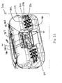
- FIG 23 shows a sharpener 300 in accordance with another embodiment of the present invention.
- the sharpener 300 may be similar to the sharpener 200 ( Figure 19 ), but is configured to sharpen one corner edge 168 ( Figure 24 ) of a snow travel member 170 such as a ski or snowboard or the like.
- the sharpener 300 is configured to sharpen one corner edge 168 at a time.
- a snow/ice travel member orienting structure for the sharpener 300 is shown at 302 may be similar to the orienting structure 16 on the sharpener 10 shown in Figure 17 and may be a channel 378 in the body 314.
- the channel 378 may have any suitable shape, such as a V-shape (best seen in Figure 24 ) having an internal angle of 90 degrees.
- the channel 378 has a bottom face receiving wall 380 and a side face receiving wall 382, for receiving the bottom face 174 ( Figure 24 ) and the side face 172 respectively of the snow travel member 170.
- the bottom face receiving wall 380 optionally includes a plurality of debris removal grooves 391 ( Figure 23 ), which collect and remove debris such as snow, dirt and ice from the bottom face 174 ( Figure 24 ) of the snow travel member 170 to inhibit the debris from getting into and damaging the drive mechanism inside and from interfering with the sharpening process.
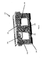
- the sharpener 300 includes a sharpening base 383 which is shown in exploded view in Figure 25 .
- the sharpening base 383 has mounted thereon a sharpening structure comprising a bottom face sharpening surface 384 and two side face sharpening surfaces 386 (shown individually at 386a and 386b), which together form a V-shape when viewed along the longitudinal direction line, and which are configured to sharpen the bottom face 174 ( Figure 24 ) and side face 172 respectively of the snow travel member 170.
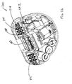
- the base support is shown at 342 ( Figure 26 ) and may be similar to the base support 280 shown in Figure 19 .
- the sharpening base 383 may mount to the base support 342 in the same way as the sharpening base 240 shown in Figure 19 .
- the sharpening surfaces 384 and 386 may be provided on tongues 385 and 387 which are integrally and resiliently joined through resilient hinge members 393 and 395 to first and second walls 388 and 389 respectively which form part of the sharpening base 383.
- the resilient connection permits the tongues to extend upwards into the channel 378 ( Figure 24 ) and to resiliently urge the sharpening surfaces 384 and 386 into engagement with the snow travel member 170 when it is pressed down into engagement with the channel 378.
- first, second and third tongues provided, namely first tongue 385, second tongue 387a and third tongue 387b and thus there are two sharpening surfaces for the side face 172 and one sharpening surface for the bottom face 174 of the snow/ice travel member 170.
- first tongue 385, second tongue 387a and third tongue 387b there are two sharpening surfaces for the side face 172 and one sharpening surface for the bottom face 174 of the snow/ice travel member 170.
- tongues and sharpening surfaces may alternatively be provided.
- the tongues (and therefore the sharpening surfaces) need not have the same longitudinal dimension.
- the snow travel member 170 is just being introduced into the channel 378 and has not yet caused flexing of the tongues 385 and 387.
- the first and second walls 388 and 389 may at their bottom ends be joined by a resilient hinge member 399, in similar manner to the first and second walls 242 and 244 and hinge member 243 of the sharpening base 240 shown in Figure 21 .
- the resilient hinge member 399 permits flexure of the first and second walls 388 and 389 towards each other for removal of the sharpening base 383 from the sharpener 300 and for urging the clip portions shown at 397, into clip receiving portions on the sharpener 300 ( Figure 23 ).
- the other elements of the sharpener 10 may be similar as appropriate to the corresponding elements of the sharpener 10 shown in Figure 17 and in the other figures.
- the sharpener 300 is moved along the length of the snow travel member 170 to permit the reciprocation of the sharpening base 383 to sharpen the corner edge 168.
- each of the embodiments described has included a drive mechanism including a motor and structure for generating reciprocating motion from the motor's rotation
- a sharpener for skates, or skis or the like that is manually operated, (ie. the sharpening is carried out by manually sliding the sharpener along the blade of the skate or ski by the user for sharpening the skate or ski).
- the manual sharpener could include a handle that has at its end a structure similar to the base support shown in any of the embodiments described and shown herein, for receiving a sharpening head in accordance with one of the embodiments described and shown herein.
Landscapes
- Engineering & Computer Science (AREA)
- Mechanical Engineering (AREA)
- Finish Polishing, Edge Sharpening, And Grinding By Specific Grinding Devices (AREA)
- Grinding And Polishing Of Tertiary Curved Surfaces And Surfaces With Complex Shapes (AREA)
- Footwear And Its Accessory, Manufacturing Method And Apparatuses (AREA)
Description
- The present invention relates to sharpeners and more particularly to portable sharpeners for snow/ice travel members such as ice skates, skis and snowboards.
- It is known to provide a sharpener for sharpening items such as skate blades. Some sharpeners, in particular some portable skate blade sharpeners, however suffer from one or more problems. For example, some sharpeners are not capable of easily accommodating skate blades of different thicknesses.
- Another problem with some sharpeners is that they are not configured to ensure that the left and right corners of a skate blade are sharpened evenly relative to each other.
- Another problem with some sharpeners is that their sharpening surfaces may be difficult and/or expensive to replace after wearing out.
- It would be advantageous to provide a sharpener that at least partially overcomes one or more of these and other problems.
-
WO 97/05988 A1 - The invention is directed to a sharpener according to claim 1 and to embodiments as defined by the dependent claims.
- The present invention will now be described by way of example only with reference to the attached drawings, in which:
-
Figure 1a is a perspective view of a sharpener in accordance with an embodiment of the present invention; -
Figure 1b is another perspective view of the sharpener shown inFigure 1a ; -
Figure 2 is a magnified perspective view of a portion of the sharpener shown inFigure 1a , which an element removed to show components hidden thereby; -
Figure 3 is a magnified end view of the sharpener shown inFigure 1a ; -
Figure 4 is another magnified perspective view of the portion of the sharpener shown inFigure 2 ; -
Figure 5 is a top plan view of the sharpener shown inFigure 1a , with an element removed to shown components hidden thereby; -
Figure 6a is a highly magnified view of sharpening components of the sharpener shown inFigure 1a ; -
Figure 6b is a highly magnified view of sharpening components of the sharpener shown inFigure 1a , with a skate blade positioned thereon; -
Figure 7a and 7b are plan views of two rotational positions for the sharpening components shown inFigures 6a and 6b ; -
Figure 8 is an end view of the sharpener shown inFigure 1a with an optional shoe for accommodating a skate blade having a different thickness; -
Figure 9 is a highly magnified view of alternative sharpening components for the sharpener shown inFigure 1a , with a skate blade positioned thereon; -
Figure 10 is a side view of the sharpener shown inFigure 1a , with an optional item engagement sensor; -
Figure 11 is a diagram of selected electrical components from the sharpener shown inFigure 10 ; -
Figure 12 is a side view of the sharpener shown inFigure 1a , with two optional item engagement sensors; -
Figure 13 is a diagram of selected electrical components from the sharpener shown inFigure 12 ; -
Figure 14 is a side view of the sharpener shown inFigure 1a , with an optional item imperfection sensor; -
Figure 15 is a diagram of selected electrical components from the sharpener shown inFigure 14 ; -
Figure 16 is a perspective view of a kit of parts including the sharpener shown inFigure 1a configured to receive a plurality of shoes for guiding different skate blades; -
Figure 16a is a plan view of the sharpener shown inFigure 16 ; -
Figure 17 is a perspective view of the sharpener shown inFigure 1a , configured to sharpen a snow travel member such as a snowboard or a ski; -
Figure 17a is a side view of a sharpening base of the sharpener shown inFigure 17 ; -
Figure 18 is a shoe for use with the sharpener shown inFigure 16 , for sharpening a snow travel member such as a snowboard or a ski; -
Figure 19 is a perspective view of a sharpener (with a portion removed) in accordance with another embodiment of the present invention; -
Figure 20 is an end view of a component (a sharpening head) from the sharpener shown inFigure 19 ; -
Figure 21 is a perspective view of the sharpening head shown inFigure 20 ; -
Figure 22 is a perspective view of the sharpening head shown inFigure 20 , shown mounted in a base support; -
Figure 22a is a sectional elevation view of the mounted sharpening head shown inFigure 22 ; -
Figure 23 is a perspective view of a sharpener (with a portion removed) in accordance with another embodiment of the present invention, for sharpening a snow travel member such as a snowboard or a ski; -
Figure 24 is a magnified elevation view of a portion of the sharpener shown inFigure 23 ; -
Figure 25 is an exploded perspective view of a sharpening head from the sharpener shown inFigure 23 ; -
Figure 26 is another perspective view of the sharpener shown inFigure 23 with a portion removed; and -
Figure 27 is a perspective view of a variant of the sharpening head shown inFigure 20 . - Reference is made to
Figure 1a , which shows asharpener 10, in accordance with an embodiment of the present invention. Thesharpener 10 may be used to sharpen askate blade 12 of a skate (not shown). Thesharpener 10 may also be used as a blade sharpness maintenance device, whereby it is used on theskate blade 12 prior to each trip a skater makes onto an ice surface. Referring toFigure 3 , theskate blade 12 includes afirst side face 78, asecond side face 80, anedge face 68, afirst corner edge 32 and asecond corner edge 34. For ease of illustration, only the lower portion of theskate blade 12 is shown in the figures. Theskate blade 12 has a thickness T. - Referring to
Figure 2 , thesharpener 10 includes abody 14, a skateblade orienting structure 16, a first corneredge sharpening structure 17a for sharpening the first corner edge 32 (Figure 6b ), a second corneredge sharpening structure 17b for sharpening the second corner edge 34 (Figure 6b ), and a drive mechanism 22 (Figure 2 ) for driving movement of the first and second corneredge sharpening structures body 14. - The
body 14 may be a two-piece assembly (seeFigure 1a ), and may be made from a suitable material such as a molded plastic. - Referring to
Figure 1b , the skateblade orienting structure 16, which in a simple incarnation is aslot 24 in thebody 14, is configured to orient the skate blade 12 (Figure 1a ) along a selecteddirection line 23 relative to the first and second corneredge sharpening structures direction line 23 may be referred to as thelongitudinal direction line 23, since the orientingstructure 16 sets the orientation of the longitudinal axis of theskate blade 12. A lateral direction line, shown at 61, is transverse to thelongitudinal direction line 23. The skateblade orienting structure 16 also centers theskate blade 12 laterally on the first and second corneredge sharpening structures - The skate
blade orienting structure 16 may have any suitable structure. For example, as shown inFigure 3 in embodiments wherein the orientingstructure 16 is theslot 24, theslot 24 has a firstslot side wall 26, a secondslot side wall 28 and aslot floor 30. The first and secondslot side walls skate blade 12. Theslot floor 30 sets the position (the height specifically) of theedge face 68 and may be referred to as an edgeface positioning surface 30. Due to the concavity of theedge face 68, theslot floor 30 may engage the first and second corner edges 32 and 34 and be spaced from theedge face 68 itself. - Referring to
Figures 2 and6a , the first and second corneredge sharpening structures base 40. The first corneredge sharpening structure 17a includes a first edgeface sharpening surface 18 and a first sideface sharpening surface 19. Similarly, the second corneredge sharpening structure 17b includes a second edgeface sharpening surface 20 and a second sideface sharpening surface 21. - As shown in
Figure 6b , the first edgeface sharpening surface 18 is positioned for sharpening theedge face 68 proximate thefirst corner edge 32, and the first sideface sharpening surface 19 is positioned for sharpening thefirst side face 78 proximate thefirst corner edge 32. Similarly, the second edgeface sharpening surface 20 is positioned for sharpening theedge face 68 proximate thesecond corner edge 34, and the second sideface sharpening surface 21 is positioned for sharpening thesecond side face 80 proximate thesecond corner edge 34. The first and second edgeface sharpening surfaces edge face 68 of theskate blade 12. - With reference to
Figure 6a , when thesharpener 10 is viewed along the longitudinal direction line 23 (which is shown inFigure 6a as a point, since thelongitudinal direction line 23 is perpendicular to the plane of the view shown in that figure), the first edgeface sharpening surface 18 and the first sideface sharpening surface 19 appear to intersect. Similarly, the second edgeface sharpening surface 20 and the second sideface sharpening surface 21 appear to intersect. This is because the first and second edgeface sharpening surfaces face sharpening surfaces Figure 6a . As a result, as thesharpener 10 is passed along the length of the skate blade 12 (Figure 6b ), the sharpeningsurfaces - As shown in
Figures 6a and 6b , the first and second sideface sharpening surfaces surfaces slot side walls Figures 6a and 6b may be exaggerated for visual clarity, however, these figures are not to be interpreted as being to scale. - The sharpening surfaces 18, 19, 20 and 21 may be made in any suitable way. For example, they may be covered with an abrasive material such as diamond, or Cubic Boron Nitride (CBN).
- As shown more clearly in
Figure 2 , the first and second edgeface sharpening surfaces second bosses base 40. It is alternatively possible for the first and second edgeface sharpening surfaces Figure 9 . The embodiment shown inFigure 9 , permits thesharpener 10 to be used to sharpen askate blade 12 outright, since it is capable of forming the entire concave surface of theedge face 68 of theskate blade 12, whereas the embodiment shown inFigure 2 with two smaller,separate bosses - The first and second side
face sharpening surfaces face sharpening structures base 40. - The sharpening
base 40 may be made removable from the rest of thesharpener 10 so that it can be replaced with a new sharpeningbase 40 when it wears out and is no longer effective. Thus, the sharpeningbase 40 may be considered to be a disposable part of thesharpener 10, and the rest of thesharpener 10 may be considered to be non-disposable, at least in some embodiments. - The sharpening
base 40 may removably lock into abase support 42, by any suitable connecting structure. For example, the sharpeningbase 40 may include a first andsecond apertures second pins base support 42. Thefirst aperture 44 may be circular and thefirst pin 48 may be circular. Thesecond aperture 46 is a keyhole slot, and thesecond pin 50 is a T-pin (ie. it is T-shaped). To mount the sharpeningbase 40 onto thebase support 42, the sharpeningbase 40 is pushed down so that thepins apertures base 40 is then rotated to lock the T-pin 50 into the narrower part of thekeyhole slot 46. It will be understood that it is alternatively or additionally possible for thefirst aperture 44 to be a keyhole slot and for thefirst pin 48 to be T-shaped. - It will be noted that the sharpening
base 40 is relatively small and may be made from a suitable plastic that is easily moldable and is relatively inexpensive or from an inexpensive grade of steel that can be stamped or from a powdered metal. Additionally, the sharpeningbase 40 can be, as shown, relatively easily removable from and installable onto thebase support 42. - The
base support 42 is driven by thedrive mechanism 22. Thedrive mechanism 22 includes amotor 52 with anoutput shaft 54 which has an offsetdrive member 56 thereon that is offset from the output shaft axis, shown at Am. Thedrive mechanism 22 further includes a first drivenmember 58 and a second drivenmember 60. The first drivenmember 58 is slidably mounted to the second drivenmember 60. The second drivenmember 60 is configured to restrict the first drivenmember 58 to only have freedom of movement approximately along thetransverse direction line 61. The second drivenmember 60 is slidably mounted on acarriage 62 and is restricted by thecarriage 62 to only have freedom of movement approximately along sliding movement approximately along thelongitudinal direction line 23. - Rotation of the
motor output shaft 54 causes the offsetdrive member 56 to 'orbit' about the motor output shaft axis Am. This orbiting path causes the first drivenmember 58 to move in the orbiting (ie. circular path). This circular path results in transverse displacement and longitudinal displacement. Because of the freedom of movement of the first driven member transversely relative to the second driven member, the transverse displacement of the first drivenmember 58 does not drive any transverse movement of the second driven member. However, because the first drivenmember 58 does not have freedom of movement longitudinally relative to the second drivenmember 60, the longitudinal displacement of the first drivenmember 58 drives longitudinal displacement of the second drivenmember 60. Thus, the second drivenmember 60 reciprocates along thelongitudinal direction line 23. - The second driven
member 60 supports thebase support 42. Thus, operation of thedrive mechanism 22 generates reciprocation of thebase support 42, and therefore the sharpeningsurfaces longitudinal direction line 23. - The second driven
member 60 has twoslide bars 64 thereon, which hold thebase support 42 and support sliding of thebase support 42 along athird direction line 65 that is transverse to the edge face positioningsurface 30. Thethird direction line 65 is vertical when thesharpener 10 is oriented as shown inFigure 2 . A biasingmember 66, shown inFigure 4 , biases thebase support 42 towards the edge face positioningsurface 30 and therefore urges the sharpeningsurfaces Figure 3 ), of theskate blade 12 when theskate blade 12 is positioned on the edge face positioningsurface 30. The biasing member 66 (Figure 4 ) may be referred to as a sharpening surface engagement biasing member, since it biases the sharpeningsurfaces skate blade 12, or alternatively a sharpening structure engagement biasing member since it biases the sharpeningstructures skate blade 12. The sharpening surfaceengagement biasing member 66 may be any suitable type of biasing member, such as a compression spring. - It should be noted that in
Figures 1 and3 , theskate blade 12 is not shown in engagement with the edge face positioningsurface 30. Also, it should be noted that, as shown inFigure 3 , the sharpeningsurfaces engagement biasing member 66 to a rest position that is past the edge face positioningsurface 30. Thus, when theskate blade 12 is positioned on the edge face positioningsurface 30, the sharpening surfaceengagement biasing member 66 is compressed by a certain amount, and therefore urges the sharpeningsurfaces skate blade 12 with a selected force, regardless of how hard a user pushes theskate blade 12 into theslot 24. In this way, even when the force of engagement between theskate blade 12 and theslot 24 varies, the force that is exerted between the sharpeningheads skate blade 12 remains consistent. - Referring to
Figures 5 ,6a and 6b , the first and second edgeface sharpening surfaces face sharpening surfaces - Referring to
Figure 5 , the size of the slot 24 (only part of which is shown inFigure 5 since a portion of thebody 14 has been omitted), and the relative positions of the sharpeningsurfaces Figure 3 ) ofskate blade 12 that can be sharpened. Thesharpener 10 may advantageously be configured to accommodate a range of thicknesses T ofskate blades 12. For this purpose, the sharpeningbase 40 may be rotated through a range of positions, which changes the lateral spacings DL1 and DL2, as shown in the two exemplary positions of the sharpeningbase 40 inFigures 7a and 7b . As a result of the clockwise rotation of the sharpeningbase 40 from the position shown inFigure 7a to the position shown inFigure 7b , the lateral spacings DL1 and DL2 have both been reduced. As a result, rotation of the sharpeningbase 40 from the position shown inFigure 7a to the position shown inFigure 7b decreases the thickness of skate blade that it is positioned to sharpen. Similarly rotation of the sharpeningbase 40 in the counterclockwise direction from the position shown inFigure 7b to the position shown inFigure 7a increases the thickness of skate blade 12 (Figure 6b ) that it is positioned to sharpen. Thus, the sharpeningbase 40 may be rotatable to adjust the relative positions of the sharpeningsurfaces skate blade 12 that can be sharpened. - Referring to
Figure 5 , to carry out the rotation of the sharpeningbase 40 thecarriage 62 may be movable relative to thebody 14. A firstcarriage biasing member 82, and a secondcarriage biasing member 84, both shown inFigure 5 , bias thecarriage 62 clockwise in the view shown inFigure 5 , which biases the sharpeningsurfaces - The
carriage biasing members face sharpening surfaces skate blade 12, at least over a working range of adjustability. When a relativelythicker skate blade 12 is introduced into thesharpener 10, the sharpeningbase 40 is rotated in a direction (counterclockwise in the view shown inFigure 5 ) that increases the spacings DL1 and DL2. As a result of the rotation of the sharpeningbase 40 to accommodate thethicker skate blade 12, thecarriage 62 is rotated against the biasing of thecarriage biasing members carriage biasing members engagement biasing members face sharpening surfaces skate blade 12. - In order that the shape of the cut in the
skate blade 12 provided by the first and second edgeface sharpening surfaces base 40, the sharpeningsurfaces surfaces - It will be noted that the rotation of the
carriage 62 when accommodatingthicker skate blades 12 means that thecarriage 62 may not initially be oriented strictly longitudinally (ie. precisely along the longitudinal direction line 23) when athicker skate blade 12 is inserted into theslot 24. Notwithstanding the misalignment of thecarriage 62 with respect to thelongitudinal direction line 23, theskate blade 12 itself prevents the movement of the sharpeningbase 40 and therefore the second drivenmember 60 along a line other than thelongitudinal direction line 23. To permit such movement, the biasingmembers carriage 62 to float sufficiently during the reciprocation of the sharpeningbase 40 and second drivenmember 60. - In an alternative embodiment the sharpening
base 40 could be rotatable relative to the second drivenmember 60 to accommodateskate blades 12 of different thicknesses. In such an alternative embodiment thecarriage 62 could be fixedly aligned longitudinally within the body 14 (such as the embodiment shown inFigure 19 ) and the biasingmembers - In order to accommodate a plurality of skate blade thicknesses T the
sharpener 10 may further include a plurality of shoes 96 (Figure 8 ) that are each sized to hold a different thickness ofskate blade 12. Eachshoe 96 would fit on thebody 14, and would have an open-bottom slot 98 therein, which has first and secondslot side walls skate blade 12 having a selected thickness T and which together form a skate blade orienting structure. By having theslot 98 be open-bottomed, theskate blade 12 is permitted to engage the edge face positioningsurface 30 so that the same force is applied by the sharpeningsurfaces skate blade 12 whether or not ashoe 96 is used. A kit ofparts 102 may be provided that includes thesharpener 10 and at least oneshoe 96 having a slot width that is different from the slot width of the slot 24 (and preferably a plurality ofinterchangeable shoes 96 of different slot widths) to accommodate a variety of skate blade thicknesses. The at least oneshoe 96 and thesharpener 10 together include a plurality of skate blade orienting structures (eg. theslots 24 and 98) wherein each skate blade orienting structure is configured for orienting a skate blade having a unique width along a longitudinal direction line and for centering theskate blade 12 laterally with respect to the edgeface sharpening surfaces shoes 96 are provided, that thesharpener 10 itself need not include a slot that constitutes a skate blade orienting structure. In such an embodiment, all the skate blade orienting structures could be provided byslots 98 in the plurality ofshoes 96. - It will be noted that it is at least possible to provide an embodiment of the invention wherein the first and second side
face sharpening surfaces face sharpening structures surfaces skate blade 12 to ensure that it is centered on the first and second edgeface sharpening surfaces face sharpening surfaces face sharpening surfaces skate blade 12 on the first and second edgeface sharpening surfaces - Referring to
Figure 2 , themotor 52 may be powered by any suitable source, such as by one ormore batteries 92. Alternatively or additionally, thesharpener 10 may include a connector (eg. a plug) for plugging into an A/C source, such as a wall outlet (not shown). - A switch shown at 94 in
Figure 1a may be provided to turn theskate sharpener 10 on. Theswitch 94 may need to be depressed by the user at all times thesharpener 10 is to be operated, such that once the user lets go of theswitch 94, theswitch 94 is urged to an 'off' position preventing current flow to themotor 52. - In use, a user turns on the
sharpener 10, and may hold the gripping surface shown at 106 (Figure 1a ) on thebody 14, and passes thesharpener 10 along theedge face 68 of theskate blade 12 so that the sharpeningsurfaces edge face 68 of theskate blade 12. - Reference is made to
Figure 10 , which shows thesharpener 10 with an optional item engagement sensor 108 that is configured to detect whether the user has inserted askate blade 12 into thesharpener 10 for sharpening. The item engagement sensor 108 may have any suitable structure. For example, the item engagement sensor 108 may be a switch 110 that is closed by aprojection 112 on thebase support 42 when theskate blade 12 is engaged with the sharpeningstructures base 40 downwards against the force of the sharpening surfaceengagement biasing member 66. - Referring to
Figure 11 , the switch 110 may communicate with acontroller 114 that controls the operation of themotor 52. As an example, thecontroller 114 may prevent operation of themotor 52 if the switch 110 is open (indicating that askate blade 12 is not present), so as to conserve energy in thebatteries 92. Therefore, if thebutton 94 is in the 'on' position (eg. it is depressed by a user), thecontroller 114 may disconnect power to themotor 52 in the event that the switch 110 is open. Furthermore, thecontroller 114 may send power to themotor 52 if thebutton 94 is 'on' and the switch 110 is closed (indicating that a skate blade 12 (Figure 10 ) is engaged and seated fully on the sharpening base 40). - With continued reference to
Figure 11 , in another embodiment theswitch 94 may be omitted. For example, thecontroller 114 may send power to themotor 52 automatically if the switch 110 is closed, and may automatically disconnect power to themotor 52 if the switch 110 is opened. Thus, the operation of themotor 52 may be automated. - Reference is made to
Figure 12 , which shows thesharpener 10 with twoitem engagement sensors 116. In the embodiment shown inFigure 12 , theitem engagement sensors 116 may be positioned in theslot 24 ahead of and behind the sharpeningbase 40. Eachitem engagement sensor 116 may include a button 117 that is slidable in a button-receivingaperture 118 in theslot floor 30, a biasing member 120 and aswitch 122. The biasing member 120 urges the button 117 to project from theslot floor 30. Placement of theskate blade 12 on theslot floor 30 depresses the buttons 117 causing closure of theswitches 122. Closure of bothswitches 122 signals a controller 124 (Figure 13 ) to permit operation of themotor 52. Similarly to the embodiment shown inFigure 11 , thecontroller 124 may disconnect power to themotor 52 if one or both of theswitches 122 is open, and may optionally send power to themotor 52 if bothswitches 122 are closed and thebutton 94 is in the 'on' position. Alternatively, thecontroller 124 may automatically control the stopping and starting of themotor 52 based on whether bothswitches 122 are closed, such that thebutton 94 may be omitted. - By incorporating a
sensor 116 on each side of the sharpeningbase 40 and requiring bothswitches 122 to be closed to permit operation of themotor 52, the user is encouraged to hold theskate blade 12 flat in theslot 24 and not to rock theskate blade 12 as it is moved forwards and backwards in theslot 24. When theskate blade 12 is held flat in theslot 24 and triggers bothswitches 122, theskate blade 12 is properly engaged with the sharpeningstructures - Reference is made to
Figure 14 , which shows thesharpener 10 with an optionalitem imperfection sensor 126 which can detect imperfections in theskate blade 12 that require smoothing out. Such imperfections, as noted above may occur, for example, as a result of blade-to-blade engagement withskate blades 12 from other skaters. Such events can occur, for example, during a game of ice hockey. Theitem imperfection sensor 126 may have any suitable structure. For example, theitem imperfection sensor 126 may be a capacitive sensor, whose capacitance changes upon exposure to an imperfection (eg. a nick) in theskate blade 12, relative to the capacitance sensed along smooth (ie. unnicked) portions of theskate blade 12. Upon encountering an imperfection, theitem imperfection sensor 126 may send a corresponding signal to a controller 128 (Figure 15 ). Upon receipt of such a signal from theitem imperfection sensor 126, thecontroller 128 may optionally notify a user that an imperfection was encountered, thereby prompting the user to send power to operate themotor 52, eg. by depressing thebutton 94. The notification to the user may be achieved in any suitable way. For example, thecontroller 128 may illuminate an indicator light (eg. an LED), or may generate an audible sound, or both, when an imperfection is encountered. In some embodiments, thecontroller 128 could automatically send power to operate themotor 52 upon encountering an imperfection in theskate blade 12, instead of, or in addition to notifying the user of the presence of the imperfection by way of audible or visible indicating means. For some types ofitem imperfection sensor 126 it may be desirable to provide one proximate eachcorner edge skate blade 12. It will be noted that in embodiments wherein thesensor 126 is provided only on one side of the sharpeningbase 40, the initiation of themotor 52 by thecontroller 94 will sharpen the imperfection only if theskate blade 12 and sharpener are being moved relative to each other in the directions shown by thedirection arrows 127. If instead theskate blade 12 and thesharpener 10 are being moved in the opposite directions to thedirection arrows 127, then the sharpeningbase 40 will not reciprocate along the imperfection. To address this, in some embodiments it may be desirable to provide onesensor 126 on either side of the sharpening base 40 (ie. both fore and aft longitudinally, of the sharpening base 40) so that the sharpeningbase 40 will be reciprocated over the imperfection regardless of which way theskate blade 12 and thesharpener 10 are being moved relative to each other. - In another embodiment the
sharpener 10 may optionally have one or more item engagement sensors for sensing the presence of askate blade 12 and also one or moreitem imperfection sensors 126. In such a case, the controller would operate themotor 52 if all of the one or more item engagement sensors indicate that askate blade 12 is engaged properly in theslot 24 and if anyitem imperfection sensor 126 indicated that an imperfection was encountered. If any item engagement sensor did not signal the presence of askate blade 12 the controller may stop themotor 52. If noitem imperfection sensors 126 signal that an imperfection is encountered, the controller may stop themotor 52. - Reference is made to
Figure 16 , which shows a kit ofparts 129 including thesharpener 10 and a plurality of optional shoes, shown generally at 130 and individually at 130a and 130b (it will be understood that more than two shoes 130 could optionally be provided). Each shoe 130 contains aslot 24 having a unique width W for accommodatingskate blades 12 having different thicknesses T. Thus, the shoe 130a has a slot 24a having a width Wa and the shoe 130b has a slot 24b having a width Wb. Each shoe 130 may be made up of afirst shoe portion 132 and asecond shoe portion 134. Thefirst shoe portion 132 slides into a firstshoe receiving slot 136 that is on a first side of the sharpeningbase 40. Thesecond shoe portion 134 slides into a secondshoe receiving slot 138 that is on a second side of the sharpeningbase 40. The first andsecond shoe portions slot 24 for receiving askate blade 12. - One or more locking features may be provided to hold the first and
second shoe portions body 14 of thesharpener 10. For example, thefirst shoe portion 132 may have flanges 140 and 142, which are received in flange receivingslot regions 144 and 146 (Figure 16a ). The engagement of thefirst shoe portion 132 and the firstshoe receiving slot 136 prevents movement of the first shoe portion transversely (ie. along the transverse direction line 61) and vertically (ie. along the third direction line 65). Afirst locking pin 148 may be provided, which passes through a first locking pin pass-throughaperture 150 in thebody 14 of thesharpener 10 and which passes into a first lockingpin receiving aperture 152 in thefirst shoe portion 132, thereby preventing movement of thefirst shoe portion 132 longitudinally (ie. along the longitudinal direction line 23). Thefirst locking pin 148 may have a mechanism for inhibiting thepin 148 from working its way out of theapertures first locking pin 148 may have aperipheral ball detent 153 thereon that engages a groove (not shown) in the first lockingpin receiving aperture 152. - Similarly to the
first shoe portion 132, thesecond shoe portion 134 may haveflanges slot regions second shoe portion 134 transversely (ie. along the transverse direction line 61) and vertically (ie. along the third direction line 65). Asecond locking pin 162 may be provided, which passes through a second locking pin pass-throughaperture 164 in thebody 14 of thesharpener 10 and which passes into a second lockingpin receiving aperture 166 in thesecond shoe portion 134, thereby preventing movement of thesecond shoe portion 134 longitudinally (ie. along the longitudinal direction line 23). Thesecond locking pin 162 may have a mechanism for inhibiting thepin 162 from working its way out of theapertures second locking pin 162 may have aperipheral ball detent 167 thereon that engages a groove (not shown) in the second lockingpin receiving aperture 166. - Once in position in the first and second
shoe receiving slots second shoe portions skate blade 12 while providing clearance for the reciprocation of the sharpeningbase 40. - Reference is made to
Figure 17 , which shows thesharpener 10 configured for sharpening acorner edge 168 of asnow travel member 170, such as a ski or a snowboard. Referring toFigure 17a , thecorner edge 168 represents the junction of aside face 172 and abottom face 174 of thesnow travel member 170. Thesharpener 10 shown inFigure 17 is configured to sharpen onecorner edge 168 at a time. As a result, the size of thesharpener 10 shown inFigure 17 may be kept small, thereby keeping it portable. - Instead of the
slot 24 shown inFigure 1b , the orientingstructure 16 for thesharpener 10 shown inFigure 17 may be, for example, a channel 178 in thebody 14, for orienting thesnow travel member 170 with respect to thesharpener 10. The channel 178 may have any suitable shape, such as a V-shape having an internal angle of about 90 degrees. The channel 178 has a bottomface receiving wall 180 and a sideface receiving wall 182, for receiving the bottom face 174 (Figure 17a ) and side face 172 of thesnow travel member 170. - The
sharpener 10 shown inFigure 17 includes a sharpeningbase 183 instead of the sharpening base 40 (Figure 2 ). The sharpeningbase 183 may, as shown inFigure 17 , has mounted thereon a sharpening structure comprising two bottom face sharpening surfaces 184 (shown individually at 184a and 184b) and a sideface sharpening surface 186, which are configured to form a V-shape when viewed along thelongitudinal direction line 23, and which are configured to sharpen the bottom face 174 (Figure 17a ) and side face 172 respectively of thesnow travel member 170. The angles of the bottom face sharpening surfaces 184 and the sideface sharpening surface 186 match those of the bottomface receiving wall 180 and side face receivingwall 182 respectively. The side face sharpeningsurface 186 may be positioned longitudinally between the two bottom face sharpening surfaces 184. The sharpeningbase 182 may mount to thebase support 42 in the same way as the sharpeningbase 40 shown inFigure 2 . - Instead of having two bottom face sharpening surfaces 184 and one side
face sharpening surface 186, it is alternatively possible to have some other combination of surfaces, such as, for example, two sideface sharpening surfaces 186 and a single bottom face sharpening surface 184. As another example, one sideface sharpening surface 186 and one bottom face sharpening surface 184 may be provided. - The other elements of the
sharpener 10 may be similar as appropriate to the corresponding elements of thesharpener 10 shown in the other figures. - During use, the
sharpener 10 is moved along the length of thesnow travel member 170 to permit the reciprocation of the sharpeningbase 40 to sharpen thecorner edge 168. It will be noted that the sharpeningbase 182 need not rotate to a different orientation about thethird direction line 65 in order to accommodateskis 170 having different thicknesses and widths. As a result, structure, such as the biasingmembers Figure 5 , that permitted the rotation of the sharpeningbase 40 about thethird direction line 65, need not be included in thesharpener 10 shown inFigure 17 . - It is optionally possible for the item engagement sensor 108 (
Figure 10 ) and/or the item engagement sensors 116 (Figure 13 ) and/or the one or more item imperfection sensors 126 (Figure 14 ) described above to be incorporated into thesharpener 10 shown inFigure 17 for use with thesnow travel member 170. - Referring to
Figure 18 , ashoe 188 may be provided which, in conjunction with the sharpeningbase 182, would permit thesharpener 10 shown inFigure 17 to sharpen asnow travel member 170, thus providing thesharpener 10 with the capability to sharpen ice skates, skis and snowboards. The shoe 188 (Figure 18 ) includes afirst shoe portion 190 and asecond shoe portion 192, which can be inserted into the first and secondshoe receiving slots sharpener 10 shown inFigure 16 . The first andsecond shoe portions bottom face 174 and side face 172 (Figure 17a ) of thesnow travel member 170. - The
sharpener 10 has been described in at least some embodiments as being configured to provide sharpening capability to a plurality of thicknesses of skate blade, and to other snow/ice travel members such as snowboards and skis, and may further be portable (with battery and/or A/C power). It is possible that at least some of the features of thesharpener 10 could be applied to a stationary (ie. non-portable) sharpener. - Reference is made to
Figure 19 , which shows asharpener 200 in accordance with another embodiment of the present invention. Thesharpener 200 may be similar to the sharpener 10 (Figure 1 ), and may include a body 202 (a portion of which is removed to show the components inside it), a skate blade orienting structure 204, a first corner edge sharpening structure 206a (Figure 20 ) for sharpening thefirst corner edge 32, a second corner edge sharpening structure 206b for sharpening the second corner edge 34 (Figure 20 ), and a drive mechanism 208 (Figure 19 ) for driving the movement of the first and second corner edge sharpening structures 206a and 206b (Figure 20 ) relative to the body 202 (Figure 19 ). - The
body 202 may be a two-piece assembly (one of the pieces is not shown, as noted above), and may be made from a suitable material such as a molded plastic. - The skate blade orienting structure 204 may be a slot 210 in the
body 202, similar to theslot 24 in thebody 14 inFigure 1 . The slot 210 has a firstslot side wall 212, a second slot side wall (not shown) and a slot floor 214. The first and second slot side walls are engageable with the first and second side faces 78 and 80 of the skate blade 12 (Figure 20 ). The slot floor 214 (Figure 19 ) sets the position (the height specifically) of the edge face 68 (Figure 20 ) and may be referred to as an edge face positioning surface 214. Due to the concavity of theedge face 68, the slot floor 214 may engage the first and second corner edges 32 and 34 and be spaced from theedge face 68 itself. - Referring to
Figures 20 and21 , the first and second corner edge sharpening structures 206a and 206b are positioned on a sharpeningbase 240. The first corner edge sharpening structure 206a includes a first edgeface sharpening surface 218 and a first sideface sharpening surface 219. Similarly, the second corner edge sharpening structure 206b includes a second edgeface sharpening surface 220 and a second sideface sharpening surface 221. - As shown in
Figure 20 , the first edgeface sharpening surface 218 is positioned for sharpening theedge face 68 proximate thefirst corner edge 32, and the first sideface sharpening surface 219 is positioned for sharpening thefirst side face 78 proximate thefirst corner edge 32. Similarly, the second edgeface sharpening surface 220 is positioned for sharpening theedge face 68 proximate thesecond corner edge 34, and the second sideface sharpening surface 221 is positioned for sharpening thesecond side face 80 proximate thesecond corner edge 34. The first and second edgeface sharpening surfaces edge face 68 of theskate blade 12. - When the sharpening
base 240 is viewed along a longitudinal direction of thesharpener 200 the first edgeface sharpening surface 218 and the first sideface sharpening surface 219 appear to intersect. Similarly, the second edgeface sharpening surface 220 and the second sideface sharpening surface 221 appear to intersect. This is because the first and second edgeface sharpening surfaces face sharpening surfaces base 240 is passed along the length of theskate blade 12, the sharpeningsurfaces - The first and second side
face sharpening surfaces surfaces Figure 19 ), so that they are ensured of engagement with the first and second side faces 78 and 80 of theskate blade 12. - The sharpening
surfaces - As shown more clearly in
Figure 21 , the first and second edgeface sharpening surfaces second tongues base 240. The first andsecond tongues second side walls base 240, such that thefirst tongue 236 is connected to thesecond side wall 244 and thesecond tongue 238 is connected to thefirst side wall 242. The resilient connections permit thetongues skate blade 12 being placed in theslot 212 into engagement with the slot floor 214. In the embodiment shown inFigure 21 , the resilient connection is provided by cutting and bending thetongues side walls face sharpening surfaces - An optional feature that prevents the tongues from being deflected by the skate blade 12 (
Figure 3 ) to the point of yielding is shown inFigure 27 . In the embodiment shown inFigure 27 , tongueflexure limit structures first side wall 242 under thefirst tongue 236 and in thesecond side wall 244 under thesecond tongue 238. Thelimit structures tongues blade 12 into the sharpening base 240 (thereby avoiding contact with the slot floor 214 (Figure 19 )), and uses too much force, thetongues - The first and
second side walls resilient hinge portion 243 at the their respective bottom ends, shown at 245 and 247. Theresilient hinge portion 243 permits the first andsecond side walls skate blade 12, but biases the first andsecond walls narrower skate blades 12. Having theintegral hinge portion 243 further saves cost, assembly time and complexity that would associated with having a separate spring member resiliently connecting the first andsecond side walls second side walls skate blade 12 could alternatively be provided. - Reference is made to
Figure 22a , which shows a sectional view of the sharpeningbase 240 mounted in thebase support 280. As shown in the figure, theclip portions 246 are connected with the clip receiving features 248, however there is room for theside walls base 240 to spread apart when receiving a skate blade 12 (Figure 20 ) therebetween. Also, it can be seen that the lower portion of the sharpeningbase 240 mounts into a mating form in thebase support 280 which ensures that the sharpeningbase 240 sits in an upright position when installed in thebase support 280. - It is alternatively possible for the first and second edge
face sharpening surfaces - The first and second side
face sharpening surfaces second side walls base 240. - Referring to
Figure 19 the sharpeningbase 240 may be made removable from the rest of thesharpener 200 so that it can be replaced with a new sharpeningbase 240 when it wears out and is no longer effective. Thus, the sharpeningbase 240 may be considered to be a disposable part of thesharpener 200, and the rest of thesharpener 200 may be considered to be non-disposable, at least in some embodiments. - Referring to
Figure 22 , the sharpeningbase 240 may removably lock into abase support 280, by any suitable connecting structure. For example, the sharpeningbase 240 may include one or more clip portions 246 (shown inFigure 20 ), which mate with clip receiving features 248 (Figure 22 ) on thebase support 280. To mount the sharpeningbase 240 onto thebase support 280, the sharpeningbase 240 is simply pushed down into the receivingslot 282 of thebase support 280. Theside walls base 240 are squeezed inwardly towards each other as the sharpeningbase 240 is pushed into place in the receivingslot 282. Once thebase 240 is in place, theclip portions 246 snap into place around the clip receiving features 248. In the view shown inFigure 21 , the molded plastic portion of the sharpeningbase 240 has been removed so as not to obscure other portions of it. - To remove a worn sharpening
base 240 from thebase support 280, the user simply squeezes theclip portions 246 together (flexing the resilient hinge member 243), which disengages the clip portions from the clip receiving features 248, at which point the sharpeningbase 240 may be pulled directly out of the receivingslot 282. - The sharpening
base 240 may be made from a suitable metal, such as a type of steel that can be stamped or from a powdered metal. Additionally, theclip portions 246 may be molded onto a metallic portion of the base 240 at a suitable position for engaging the clip receiving features 248. - Referring to
Figure 19 , thebase support 280 is driven by thedrive mechanism 208. Thedrive mechanism 208 includes amotor 252 with anoutput shaft 254 which has an offsetdrive member 256 thereon that is offset from the output shaft axis. Thedrive mechanism 208 further includes a first drivenmember 258 and a second drivenmember 260. The first drivenmember 258 is slidably mounted to the second drivenmember 260. The second drivenmember 260 is configured to restrict the first drivenmember 258 to only have freedom of movement approximately along a transverse direction line shown at 261. The second drivenmember 260 is slidably mounted on rails (not shown) and is restricted by the rails to only have freedom of movement along the longitudinal direction line shown at 223. The rails are integral with thebody 202. The second drivenmember 260 is integral with thebase support 280. - Operation of the
drive mechanism 208 generates reciprocation of thebase support 42, and therefore the sharpeningsurfaces drive mechanism 22 in the embodiment shown inFigure 2 . - In the event that a
skate blade 12 that is thinner than theslot 212 is inserted in theslot 212 for sharpening, it is possible that theskate blade 12 could be rotated slightly so that it was not strictly aligned with the longitudinal direction line 223. It will be noted that the structure of the sharpeningbase 240 permits some angular misalignment in theblade 12 relative to thesharpener 200 while keeping the sharpeningsurfaces skate blade 12 itself. - Reference is made to
Figure 23 , which shows asharpener 300 in accordance with another embodiment of the present invention. Thesharpener 300 may be similar to the sharpener 200 (Figure 19 ), but is configured to sharpen one corner edge 168 (Figure 24 ) of asnow travel member 170 such as a ski or snowboard or the like. Thesharpener 300 is configured to sharpen onecorner edge 168 at a time. - A snow/ice travel member orienting structure for the
sharpener 300 is shown at 302 may be similar to the orientingstructure 16 on thesharpener 10 shown inFigure 17 and may be achannel 378 in thebody 314. Thechannel 378 may have any suitable shape, such as a V-shape (best seen inFigure 24 ) having an internal angle of 90 degrees. Thechannel 378 has a bottomface receiving wall 380 and a sideface receiving wall 382, for receiving the bottom face 174 (Figure 24 ) and theside face 172 respectively of thesnow travel member 170. The bottomface receiving wall 380 optionally includes a plurality of debris removal grooves 391 (Figure 23 ), which collect and remove debris such as snow, dirt and ice from the bottom face 174 (Figure 24 ) of thesnow travel member 170 to inhibit the debris from getting into and damaging the drive mechanism inside and from interfering with the sharpening process. - The
sharpener 300 includes a sharpeningbase 383 which is shown in exploded view inFigure 25 . The sharpeningbase 383 has mounted thereon a sharpening structure comprising a bottomface sharpening surface 384 and two side face sharpening surfaces 386 (shown individually at 386a and 386b), which together form a V-shape when viewed along the longitudinal direction line, and which are configured to sharpen the bottom face 174 (Figure 24 ) and side face 172 respectively of thesnow travel member 170. The base support is shown at 342 (Figure 26 ) and may be similar to thebase support 280 shown inFigure 19 . The sharpeningbase 383 may mount to thebase support 342 in the same way as the sharpeningbase 240 shown inFigure 19 . - Referring to
Figure 25 , the sharpeningsurfaces resilient hinge members 393 and 395 to first andsecond walls base 383. The resilient connection permits the tongues to extend upwards into the channel 378 (Figure 24 ) and to resiliently urge the sharpeningsurfaces snow travel member 170 when it is pressed down into engagement with thechannel 378. In the embodiment shown, there are first, second and third tongues provided, namely first tongue 385, second tongue 387a and third tongue 387b and thus there are two sharpening surfaces for theside face 172 and one sharpening surface for thebottom face 174 of the snow/ice travel member 170. However, other combinations of tongues and sharpening surfaces may alternatively be provided. There may be the same number of tongues for sharpening the side face as there are for the bottom face. There may be more tongues for the bottom face than for the side face. The tongues (and therefore the sharpening surfaces) need not have the same longitudinal dimension. In the view shown inFigure 24 , thesnow travel member 170 is just being introduced into thechannel 378 and has not yet caused flexing of the tongues 385 and 387. - The first and
second walls resilient hinge member 399, in similar manner to the first andsecond walls member 243 of the sharpeningbase 240 shown inFigure 21 . Theresilient hinge member 399 permits flexure of the first andsecond walls base 383 from thesharpener 300 and for urging the clip portions shown at 397, into clip receiving portions on the sharpener 300 (Figure 23 ). - The other elements of the
sharpener 10 may be similar as appropriate to the corresponding elements of thesharpener 10 shown inFigure 17 and in the other figures. - During use, the
sharpener 300 is moved along the length of thesnow travel member 170 to permit the reciprocation of the sharpeningbase 383 to sharpen thecorner edge 168. - While each of the embodiments described has included a drive mechanism including a motor and structure for generating reciprocating motion from the motor's rotation, it is alternatively possible to provide a sharpener for skates, or skis or the like, that is manually operated, (ie. the sharpening is carried out by manually sliding the sharpener along the blade of the skate or ski by the user for sharpening the skate or ski). For example, the manual sharpener could include a handle that has at its end a structure similar to the base support shown in any of the embodiments described and shown herein, for receiving a sharpening head in accordance with one of the embodiments described and shown herein.
- While the above description constitutes a plurality of embodiments of the present invention, it will be appreciated that the present invention is susceptible to further modification and change without departing from the scope of the accompanying claims.
Claims (11)
- A sharpener (10), comprising:a body (14);a skate blade orienting structure (16), configured to orient a skate blade (12) along a longitudinal direction line (23), characterised bya first sharpening surface (17a) positioned for sharpening a first corner edge (32) of the skate blade (12) and a second sharpening surface (17b) positioned for sharpening a second corner edge (34) of the skate blade (12); anda drive mechanism (22) configured to move the first and second sharpening surfaces (17a, 17b) reciprocally relative to the body along a reciprocation path along the longitudinal direction line (23), wherein the body includes an edge face positioning surface (30) for receiving an edge face (68) of the skate blade (12), and wherein the sharpener (10) further includes a sharpening surface engagement biasing member (66) that is configured to urge the first and second sharpening surfaces (17a, 17b) to the edge face.
- The sharpener (10) as claimed in claim 1, wherein the drive mechanism (22) includes a motor.
- The sharpener (10) as claimed in claim 1, further comprising a first skate blade side face guide surface and a second skate blade side face guide surface, wherein the first and second skate blade side face guide surfaces are spaced apart from each other laterally by a lateral spacing and configured to receive therebetween the skate blade (12) and for centering the skate blade on the first and second sharpening surfaces (17a, 17b),
wherein the first and second skate blade side face guide surfaces include an abrasive thereon for sharpening a first side face and a second side face of the skate blade. - The sharpener (10) as claimed in claim 1, further comprising at least one item engagement sensor (108, 116) positioned to sense the engagement of the skate blade with the sharpening surface.
- The sharpener (10) as claimed in claim 4, wherein the item engagement sensor (108, 116) is positioned to detect movement of the sharpening surface against the force of the sharpening surface engagement biasing member (66).
- The sharpener (10) as claimed in claim 1, wherein the first and second sharpening surfaces (17a, 17b) are provided on a disposable element (40) that is removably connectable to a non-disposable portion of the sharpener (10).
- The sharpener (10) as claimed in claim 6, wherein the disposable element is a sharpening base (40), and wherein the first and second sharpening surfaces (17a, 17b) and the sharpening surface biasing member (66) are integral with each other.
- The sharpener (10) as claimed in claim 7, wherein the sharpening base (40) includes a first wall and a second wall, wherein the first and second sharpening surfaces (17a, 17b) and the at least one sharpening surface biasing member (66) are positioned on at least one tongue that extends from at least one of the first and second walls towards the other of the first and second walls.
- The sharpener (10) as claimed in claim 8, wherein the first and second walls each have a bottom end and wherein the sharpening base further comprises a resilient hinge member that connects the first and second walls together at the bottoms ends and biases the first and second walls towards a rest position.
- The sharpener (10) as claimed in claim 7, wherein the sharpening base (40) includes a first wall and a second wall, wherein the first sharpening surface (17a) includes a first edge face sharpening surface (18) and a first side face sharpening surface (19), wherein the first edge face sharpening surface and the first side face sharpening surface are positioned on a first tongue that extends from one of the first and second walls towards the other of the first and second walls, and wherein the first edge face sharpening surface and the first side face sharpening surface cooperate to sharpen a first corner edge of the skate blade,
and wherein the second sharpening surface (17b) includes a second edge face sharpening surface (20) and a second side face sharpening surface (21), wherein the second edge face sharpening surface and the second side face sharpening surface are positioned on a second tongue that extends from the other of the first and second walls towards the one of the first and second walls, and wherein the second edge face sharpening surface and the second side face sharpening surface cooperate to sharpen a second corner edge of the skate blade. - A sharpener as claimed in claim 10, further comprising first and second tongue flexure limit structures positioned to limit the travel of the first and second tongues respective.
Priority Applications (1)
| Application Number | Priority Date | Filing Date | Title |
|---|---|---|---|
| EP14002413.4A EP2796241B1 (en) | 2008-12-19 | 2009-12-21 | Reciprocating skate blade sharpener |
Applications Claiming Priority (4)
| Application Number | Priority Date | Filing Date | Title |
|---|---|---|---|
| US13917108P | 2008-12-19 | 2008-12-19 | |
| US16636709P | 2009-04-03 | 2009-04-03 | |
| US24369809P | 2009-09-18 | 2009-09-18 | |
| PCT/CA2009/001890 WO2010069082A1 (en) | 2008-12-19 | 2009-12-21 | Reciprocating skate blade sharpener |
Related Child Applications (1)
| Application Number | Title | Priority Date | Filing Date |
|---|---|---|---|
| EP14002413.4A Division EP2796241B1 (en) | 2008-12-19 | 2009-12-21 | Reciprocating skate blade sharpener |
Publications (3)
| Publication Number | Publication Date |
|---|---|
| EP2379279A1 EP2379279A1 (en) | 2011-10-26 |
| EP2379279A4 EP2379279A4 (en) | 2013-07-10 |
| EP2379279B1 true EP2379279B1 (en) | 2014-07-16 |
Family
ID=42268238
Family Applications (2)
| Application Number | Title | Priority Date | Filing Date |
|---|---|---|---|
| EP09832796.8A Active EP2379279B1 (en) | 2008-12-19 | 2009-12-21 | Reciprocating skate blade sharpener |
| EP14002413.4A Active EP2796241B1 (en) | 2008-12-19 | 2009-12-21 | Reciprocating skate blade sharpener |
Family Applications After (1)
| Application Number | Title | Priority Date | Filing Date |
|---|---|---|---|
| EP14002413.4A Active EP2796241B1 (en) | 2008-12-19 | 2009-12-21 | Reciprocating skate blade sharpener |
Country Status (6)
| Country | Link |
|---|---|
| US (2) | US8944889B2 (en) |
| EP (2) | EP2379279B1 (en) |
| CN (1) | CN102292191A (en) |
| CA (2) | CA3005383C (en) |
| RU (1) | RU2551732C2 (en) |
| WO (1) | WO2010069082A1 (en) |
Families Citing this family (15)
| Publication number | Priority date | Publication date | Assignee | Title |
|---|---|---|---|---|
| CA2759485C (en) * | 2010-12-17 | 2019-02-26 | Magna Closures Inc. | Sharpener for a snow travel member such as a ski or a snowboard |
| US9878229B2 (en) | 2013-03-11 | 2018-01-30 | Bauer Hockey, Llc | Skate with injected boot form |
| CA2930079A1 (en) | 2016-05-12 | 2017-11-12 | Skatescribe Corporation | Methods of customizing ice blades and their use |
| GB201602164D0 (en) * | 2016-02-05 | 2016-03-23 | Jrc Innovation Ltd | Polishing apparatus |
| US10384329B2 (en) | 2017-02-06 | 2019-08-20 | Maintain Your Edge, Llc | Skate blade sharpener with indexing stone |
| US10864611B2 (en) * | 2017-05-12 | 2020-12-15 | Utitec, Inc. | Method of sharpening hardened thin metal blades |
| CA2987362C (en) * | 2017-12-01 | 2025-12-23 | Timothy Maxwell | Manual blade sharpening tool |
| CN110465068A (en) * | 2018-05-09 | 2019-11-19 | 叶荣春 | Skates edger |
| CA3078002C (en) | 2019-04-23 | 2025-09-23 | Maintain Your Edge, Llc | Handheld skate blade sharpener |
| US11806826B2 (en) | 2019-09-11 | 2023-11-07 | Prosharp Inc. | Automatic blade holder |
| US11878386B2 (en) | 2019-09-11 | 2024-01-23 | Prosharp Inc. | Automatic blade holder |
| US11819973B1 (en) | 2020-04-14 | 2023-11-21 | Dalibor Gajdos | Self-service ice skate blade sharpening machine |
| US20220410333A1 (en) * | 2021-06-23 | 2022-12-29 | Lukas J. Kirby | Skate blade sharpening device |
| EP4508388A1 (en) * | 2022-04-15 | 2025-02-19 | Velasa Sports, Inc. | Device and methods for measuring and analyzing geometry in ice skate blades |
| CA3261315A1 (en) * | 2022-07-01 | 2024-01-04 | Velasa Sports, Inc. | Devices, systems, and methods for skate blade alignment in a skate sharpening system |
Family Cites Families (44)
| Publication number | Priority date | Publication date | Assignee | Title |
|---|---|---|---|---|
| US3597880A (en) | 1969-03-14 | 1971-08-10 | Leo I Norgiel | Ice-skating grinding apparatus |
| US3585880A (en) | 1969-10-07 | 1971-06-22 | Bohuslav Kabriel | Ice skate sharpening tool |
| US3719006A (en) * | 1970-08-03 | 1973-03-06 | Smith P | Skate sharpening machine |
| US3827185A (en) | 1971-07-29 | 1974-08-06 | Match E Co Ltd | Ice skate sharpening apparatus |
| US3812626A (en) | 1972-09-01 | 1974-05-28 | A Thompson | Ice skate sharpening device |
| US3921341A (en) | 1972-09-07 | 1975-11-25 | Arnold M Thompson | Ice skate honing tool |
| US3839828A (en) | 1973-02-21 | 1974-10-08 | R Arnold | Method and apparatus for sharpening skates |
| CA984611A (en) * | 1973-07-13 | 1976-03-02 | Thomas F. Grifferty | Skate sharpening machine |
| US3841030A (en) | 1973-08-24 | 1974-10-15 | A Laszlo | Sharpener device |
| US3875825A (en) * | 1974-02-07 | 1975-04-08 | Bennie P Buttafuoco | Ski sharpener |
| US4060013A (en) * | 1976-06-11 | 1977-11-29 | Gold Lode, Inc. | Ski-renovating or conditioning tool |
| CA1118514A (en) | 1978-07-13 | 1982-02-16 | James H. Hannaford | Skate sharpening apparatus |
| US4241544A (en) | 1978-10-30 | 1980-12-30 | Joseph Hampton | Skate blade sharpener |
| US4219975A (en) | 1978-11-28 | 1980-09-02 | Martin Scholler | Skate sharpener |
| US4442636A (en) * | 1982-01-22 | 1984-04-17 | Obland Donald R | Dual head edge sharpening device for skis |
| US4569158A (en) * | 1983-09-16 | 1986-02-11 | Curmi David M | Ski sharpening tool |
| CA1198896A (en) | 1984-08-09 | 1986-01-07 | Martin T. Carew | Portable skate sharpener |
| SU1235511A1 (en) * | 1985-01-03 | 1986-06-07 | Ленинградское Особое Конструкторское Бюро Автоматов И Револьверных Станков | Arrangement for sharpening a skate |
| SU1340776A1 (en) * | 1985-10-18 | 1987-09-30 | Всесоюзный научно-исследовательский и конструкторско-технологический институт природных алмазов и инструмента | Arrangement for sharpening skates |
| SE450221B (en) * | 1985-11-07 | 1987-06-15 | Thomas Weidmo | PROCEDURE AND DEVICE FOR GRINDING OF LONG-TERM FORMAL, SPECIAL EDGE GRINDING OF FORMAL |
| US4665778A (en) * | 1986-03-31 | 1987-05-19 | Flying Camel, Ltd. | Torque loaded ski tuning device |
| US4910923A (en) | 1987-09-30 | 1990-03-27 | Mccabe Edgar H | Sharpening tool |
| SU1491534A1 (en) * | 1987-11-23 | 1989-07-07 | Всесоюзный Заочный Политехнический Институт | Device for dressing skate blade |
| US4815240A (en) | 1988-03-11 | 1989-03-28 | Larson Clifford M | Hand-held skate sharpener |
| JPH0248155A (en) | 1988-08-08 | 1990-02-16 | Kazumasa Miwa | Diamond polisher for ice skate edge |
| US5103597A (en) | 1990-06-14 | 1992-04-14 | Courchesne Richard L | Blade sharpening device |
| US5189845A (en) | 1990-06-14 | 1993-03-02 | Courchesne Richard L | Blade sharpening device and method |
| US5195277A (en) | 1990-06-14 | 1993-03-23 | Courchesne Richard L | Blade sharpening method |
| SE9003211L (en) | 1990-10-09 | 1992-01-27 | Everett M Ellestad | DEVICE FOR GRINDING OF SKATE BOOTS |
| US5287657A (en) | 1992-05-22 | 1994-02-22 | Contract Design, Inc. | Skate sharpening machine and method |
| US5239785A (en) | 1992-06-16 | 1993-08-31 | Allen Robert H | Method and tool for finishing of sharpened skate blades |
| US5431597A (en) | 1993-04-12 | 1995-07-11 | Edge Specialties, Inc. | Skate blade edge resurfacer |
| US5445050A (en) | 1993-12-30 | 1995-08-29 | Owens; Michael R. | Hand-held ice skate blade sharpener tool |
| US5591069A (en) | 1994-11-14 | 1997-01-07 | Wurthman; Michael H. | Portable blade sharpener for ice skates |
| US5499556A (en) | 1995-04-07 | 1996-03-19 | Walter R. Exner | Portable ice skate blade sharpener |
| US5492037A (en) | 1995-04-17 | 1996-02-20 | Graham; Gilbert B. | Skate sharpening mechanism |
| US5607347A (en) | 1995-05-19 | 1997-03-04 | Arosport Marketing, Inc. | Ice skate blade sharpener |
| AU4617596A (en) | 1995-06-05 | 1996-12-24 | Rinkratz International Inc | Tool for refurbishing skate blades |
| GB2304063A (en) | 1995-08-04 | 1997-03-12 | Anthony Osler Mcintyre | Skate blade sharpener |
| US6030283A (en) | 1996-03-04 | 2000-02-29 | Edge Specialties, Inc | Ice skate blade sharpener |
| US5879229A (en) | 1997-06-18 | 1999-03-09 | Edge Specialities, Inc. | Ice skate blade resurfacer |
| US6312017B1 (en) | 2000-04-05 | 2001-11-06 | Jarr Canada | Skate guard with sharpener |
| WO2003099395A1 (en) | 2002-05-24 | 2003-12-04 | Robert Mccroary | Handheld skate sharpener |
| US6726543B1 (en) | 2003-04-18 | 2004-04-27 | Klawhorn Industries, Inc. | Skate blade sharpening apparatus and method |
-
2009
- 2009-12-21 CN CN2009801550716A patent/CN102292191A/en active Pending
- 2009-12-21 WO PCT/CA2009/001890 patent/WO2010069082A1/en not_active Ceased
- 2009-12-21 EP EP09832796.8A patent/EP2379279B1/en active Active
- 2009-12-21 US US13/139,895 patent/US8944889B2/en active Active
- 2009-12-21 CA CA3005383A patent/CA3005383C/en active Active
- 2009-12-21 EP EP14002413.4A patent/EP2796241B1/en active Active
- 2009-12-21 CA CA2746347A patent/CA2746347C/en active Active
- 2009-12-21 RU RU2011126264/02A patent/RU2551732C2/en active
-
2014
- 2014-12-15 US US14/570,880 patent/US9895786B2/en not_active Expired - Fee Related
Also Published As
| Publication number | Publication date |
|---|---|
| CA2746347A1 (en) | 2010-06-24 |
| CA2746347C (en) | 2018-07-03 |
| EP2796241B1 (en) | 2015-09-09 |
| EP2379279A4 (en) | 2013-07-10 |
| CA3005383C (en) | 2020-07-07 |
| EP2796241A1 (en) | 2014-10-29 |
| US20110247460A1 (en) | 2011-10-13 |
| CN102292191A (en) | 2011-12-21 |
| CA3005383A1 (en) | 2010-06-24 |
| US20150099436A1 (en) | 2015-04-09 |
| WO2010069082A1 (en) | 2010-06-24 |
| RU2011126264A (en) | 2013-01-27 |
| RU2551732C2 (en) | 2015-05-27 |
| EP2379279A1 (en) | 2011-10-26 |
| US8944889B2 (en) | 2015-02-03 |
| US9895786B2 (en) | 2018-02-20 |
Similar Documents
| Publication | Publication Date | Title |
|---|---|---|
| EP2796241B1 (en) | Reciprocating skate blade sharpener | |
| US9242331B2 (en) | Electric sharpener for ceramic and metal blades | |
| US11369857B2 (en) | Polishing apparatus | |
| CN116998329A (en) | Wheel attachments for garden tools | |
| US7097547B2 (en) | Handheld skate sharpener | |
| CA2759485C (en) | Sharpener for a snow travel member such as a ski or a snowboard | |
| US20190366500A1 (en) | Knife sharpener | |
| EP1178870A1 (en) | Blade sharpening | |
| US5916018A (en) | Sharpener: iceskate blades, iceboat and bobsled runners | |
| KR100904980B1 (en) | Polishing drum for electric knife grinder | |
| KR200485360Y1 (en) | Knife grinding device | |
| EP1536915A1 (en) | Sharpening apparatus | |
| JP3206709U (en) | Grinder and auxiliary equipment for gliding equipment | |
| KR200314805Y1 (en) | A nife sharpener | |
| KR200354826Y1 (en) | Auto knife sharpener | |
| JPH02243255A (en) | Cutter polisher | |
| US20160243665A1 (en) | Razor Blade Sharpening Device and Method | |
| CA2616634A1 (en) | Hand held ice skate sharpener | |
| JP2014034104A (en) | Blade polishing device | |
| BRPI0400199B1 (en) | sharpener set |
Legal Events
| Date | Code | Title | Description |
|---|---|---|---|
| PUAI | Public reference made under article 153(3) epc to a published international application that has entered the european phase |
Free format text: ORIGINAL CODE: 0009012 |
|
| 17P | Request for examination filed |
Effective date: 20110630 |
|
| AK | Designated contracting states |
Kind code of ref document: A1 Designated state(s): AT BE BG CH CY CZ DE DK EE ES FI FR GB GR HR HU IE IS IT LI LT LU LV MC MK MT NL NO PL PT RO SE SI SK SM TR |
|
| DAX | Request for extension of the european patent (deleted) | ||
| A4 | Supplementary search report drawn up and despatched |
Effective date: 20130612 |
|
| RIC1 | Information provided on ipc code assigned before grant |
Ipc: A63C 3/10 20060101ALI20130606BHEP Ipc: B24B 9/04 20060101AFI20130606BHEP |
|
| GRAP | Despatch of communication of intention to grant a patent |
Free format text: ORIGINAL CODE: EPIDOSNIGR1 |
|
| INTG | Intention to grant announced |
Effective date: 20140129 |
|
| RAP1 | Party data changed (applicant data changed or rights of an application transferred) |
Owner name: MAGNA CLOSURES INC. |
|
| GRAS | Grant fee paid |
Free format text: ORIGINAL CODE: EPIDOSNIGR3 |
|
| GRAA | (expected) grant |
Free format text: ORIGINAL CODE: 0009210 |
|
| AK | Designated contracting states |
Kind code of ref document: B1 Designated state(s): AT BE BG CH CY CZ DE DK EE ES FI FR GB GR HR HU IE IS IT LI LT LU LV MC MK MT NL NO PL PT RO SE SI SK SM TR |
|
| REG | Reference to a national code |
Ref country code: GB Ref legal event code: FG4D |
|
| REG | Reference to a national code |
Ref country code: CH Ref legal event code: EP |
|
| REG | Reference to a national code |
Ref country code: IE Ref legal event code: FG4D |
|
| REG | Reference to a national code |
Ref country code: AT Ref legal event code: REF Ref document number: 677300 Country of ref document: AT Kind code of ref document: T Effective date: 20140815 |
|
| REG | Reference to a national code |
Ref country code: DE Ref legal event code: R096 Ref document number: 602009025408 Country of ref document: DE Effective date: 20140828 |
|
| REG | Reference to a national code |
Ref country code: CH Ref legal event code: NV Representative=s name: BRAUNPAT BRAUN EDER AG, CH |
|
| REG | Reference to a national code |
Ref country code: SE Ref legal event code: TRGR |
|
| REG | Reference to a national code |
Ref country code: NL Ref legal event code: VDEP Effective date: 20140716 |
|
| REG | Reference to a national code |
Ref country code: AT Ref legal event code: MK05 Ref document number: 677300 Country of ref document: AT Kind code of ref document: T Effective date: 20140716 |
|
| REG | Reference to a national code |
Ref country code: LT Ref legal event code: MG4D |
|
| PG25 | Lapsed in a contracting state [announced via postgrant information from national office to epo] |
Ref country code: LT Free format text: LAPSE BECAUSE OF FAILURE TO SUBMIT A TRANSLATION OF THE DESCRIPTION OR TO PAY THE FEE WITHIN THE PRESCRIBED TIME-LIMIT Effective date: 20140716 Ref country code: NO Free format text: LAPSE BECAUSE OF FAILURE TO SUBMIT A TRANSLATION OF THE DESCRIPTION OR TO PAY THE FEE WITHIN THE PRESCRIBED TIME-LIMIT Effective date: 20141016 Ref country code: BG Free format text: LAPSE BECAUSE OF FAILURE TO SUBMIT A TRANSLATION OF THE DESCRIPTION OR TO PAY THE FEE WITHIN THE PRESCRIBED TIME-LIMIT Effective date: 20141016 Ref country code: PT Free format text: LAPSE BECAUSE OF FAILURE TO SUBMIT A TRANSLATION OF THE DESCRIPTION OR TO PAY THE FEE WITHIN THE PRESCRIBED TIME-LIMIT Effective date: 20141117 Ref country code: ES Free format text: LAPSE BECAUSE OF FAILURE TO SUBMIT A TRANSLATION OF THE DESCRIPTION OR TO PAY THE FEE WITHIN THE PRESCRIBED TIME-LIMIT Effective date: 20140716 Ref country code: GR Free format text: LAPSE BECAUSE OF FAILURE TO SUBMIT A TRANSLATION OF THE DESCRIPTION OR TO PAY THE FEE WITHIN THE PRESCRIBED TIME-LIMIT Effective date: 20141017 |
|
| PGFP | Annual fee paid to national office [announced via postgrant information from national office to epo] |
Ref country code: GB Payment date: 20141217 Year of fee payment: 6 Ref country code: DE Payment date: 20141216 Year of fee payment: 6 Ref country code: FI Payment date: 20141209 Year of fee payment: 6 |
|
| PG25 | Lapsed in a contracting state [announced via postgrant information from national office to epo] |
Ref country code: HR Free format text: LAPSE BECAUSE OF FAILURE TO SUBMIT A TRANSLATION OF THE DESCRIPTION OR TO PAY THE FEE WITHIN THE PRESCRIBED TIME-LIMIT Effective date: 20140716 Ref country code: NL Free format text: LAPSE BECAUSE OF FAILURE TO SUBMIT A TRANSLATION OF THE DESCRIPTION OR TO PAY THE FEE WITHIN THE PRESCRIBED TIME-LIMIT Effective date: 20140716 Ref country code: CY Free format text: LAPSE BECAUSE OF FAILURE TO SUBMIT A TRANSLATION OF THE DESCRIPTION OR TO PAY THE FEE WITHIN THE PRESCRIBED TIME-LIMIT Effective date: 20140716 Ref country code: IS Free format text: LAPSE BECAUSE OF FAILURE TO SUBMIT A TRANSLATION OF THE DESCRIPTION OR TO PAY THE FEE WITHIN THE PRESCRIBED TIME-LIMIT Effective date: 20141116 Ref country code: AT Free format text: LAPSE BECAUSE OF FAILURE TO SUBMIT A TRANSLATION OF THE DESCRIPTION OR TO PAY THE FEE WITHIN THE PRESCRIBED TIME-LIMIT Effective date: 20140716 Ref country code: PL Free format text: LAPSE BECAUSE OF FAILURE TO SUBMIT A TRANSLATION OF THE DESCRIPTION OR TO PAY THE FEE WITHIN THE PRESCRIBED TIME-LIMIT Effective date: 20140716 Ref country code: LV Free format text: LAPSE BECAUSE OF FAILURE TO SUBMIT A TRANSLATION OF THE DESCRIPTION OR TO PAY THE FEE WITHIN THE PRESCRIBED TIME-LIMIT Effective date: 20140716 |
|
| REG | Reference to a national code |
Ref country code: DE Ref legal event code: R097 Ref document number: 602009025408 Country of ref document: DE |
|
| PG25 | Lapsed in a contracting state [announced via postgrant information from national office to epo] |
Ref country code: SK Free format text: LAPSE BECAUSE OF FAILURE TO SUBMIT A TRANSLATION OF THE DESCRIPTION OR TO PAY THE FEE WITHIN THE PRESCRIBED TIME-LIMIT Effective date: 20140716 Ref country code: CZ Free format text: LAPSE BECAUSE OF FAILURE TO SUBMIT A TRANSLATION OF THE DESCRIPTION OR TO PAY THE FEE WITHIN THE PRESCRIBED TIME-LIMIT Effective date: 20140716 Ref country code: IT Free format text: LAPSE BECAUSE OF FAILURE TO SUBMIT A TRANSLATION OF THE DESCRIPTION OR TO PAY THE FEE WITHIN THE PRESCRIBED TIME-LIMIT Effective date: 20140716 Ref country code: RO Free format text: LAPSE BECAUSE OF FAILURE TO SUBMIT A TRANSLATION OF THE DESCRIPTION OR TO PAY THE FEE WITHIN THE PRESCRIBED TIME-LIMIT Effective date: 20140716 Ref country code: DK Free format text: LAPSE BECAUSE OF FAILURE TO SUBMIT A TRANSLATION OF THE DESCRIPTION OR TO PAY THE FEE WITHIN THE PRESCRIBED TIME-LIMIT Effective date: 20140716 Ref country code: EE Free format text: LAPSE BECAUSE OF FAILURE TO SUBMIT A TRANSLATION OF THE DESCRIPTION OR TO PAY THE FEE WITHIN THE PRESCRIBED TIME-LIMIT Effective date: 20140716 |
|
| PLBE | No opposition filed within time limit |
Free format text: ORIGINAL CODE: 0009261 |
|
| STAA | Information on the status of an ep patent application or granted ep patent |
Free format text: STATUS: NO OPPOSITION FILED WITHIN TIME LIMIT |
|
| 26N | No opposition filed |
Effective date: 20150417 |
|
| PG25 | Lapsed in a contracting state [announced via postgrant information from national office to epo] |
Ref country code: BE Free format text: LAPSE BECAUSE OF NON-PAYMENT OF DUE FEES Effective date: 20141231 |
|
| PG25 | Lapsed in a contracting state [announced via postgrant information from national office to epo] |
Ref country code: LU Free format text: LAPSE BECAUSE OF FAILURE TO SUBMIT A TRANSLATION OF THE DESCRIPTION OR TO PAY THE FEE WITHIN THE PRESCRIBED TIME-LIMIT Effective date: 20141221 |
|
| REG | Reference to a national code |
Ref country code: IE Ref legal event code: MM4A |
|
| PG25 | Lapsed in a contracting state [announced via postgrant information from national office to epo] |
Ref country code: IE Free format text: LAPSE BECAUSE OF NON-PAYMENT OF DUE FEES Effective date: 20141221 |
|
| REG | Reference to a national code |
Ref country code: FR Ref legal event code: PLFP Year of fee payment: 7 |
|
| PG25 | Lapsed in a contracting state [announced via postgrant information from national office to epo] |
Ref country code: SI Free format text: LAPSE BECAUSE OF FAILURE TO SUBMIT A TRANSLATION OF THE DESCRIPTION OR TO PAY THE FEE WITHIN THE PRESCRIBED TIME-LIMIT Effective date: 20140716 |
|
| PGFP | Annual fee paid to national office [announced via postgrant information from national office to epo] |
Ref country code: CH Payment date: 20151211 Year of fee payment: 7 |
|
| PGFP | Annual fee paid to national office [announced via postgrant information from national office to epo] |
Ref country code: FR Payment date: 20151110 Year of fee payment: 7 |
|
| PG25 | Lapsed in a contracting state [announced via postgrant information from national office to epo] |
Ref country code: SM Free format text: LAPSE BECAUSE OF FAILURE TO SUBMIT A TRANSLATION OF THE DESCRIPTION OR TO PAY THE FEE WITHIN THE PRESCRIBED TIME-LIMIT Effective date: 20140716 |
|
| PG25 | Lapsed in a contracting state [announced via postgrant information from national office to epo] |
Ref country code: MC Free format text: LAPSE BECAUSE OF FAILURE TO SUBMIT A TRANSLATION OF THE DESCRIPTION OR TO PAY THE FEE WITHIN THE PRESCRIBED TIME-LIMIT Effective date: 20140716 |
|
| REG | Reference to a national code |
Ref country code: DE Ref legal event code: R119 Ref document number: 602009025408 Country of ref document: DE |
|
| PG25 | Lapsed in a contracting state [announced via postgrant information from national office to epo] |
Ref country code: TR Free format text: LAPSE BECAUSE OF FAILURE TO SUBMIT A TRANSLATION OF THE DESCRIPTION OR TO PAY THE FEE WITHIN THE PRESCRIBED TIME-LIMIT Effective date: 20140716 Ref country code: MT Free format text: LAPSE BECAUSE OF FAILURE TO SUBMIT A TRANSLATION OF THE DESCRIPTION OR TO PAY THE FEE WITHIN THE PRESCRIBED TIME-LIMIT Effective date: 20140716 Ref country code: HU Free format text: LAPSE BECAUSE OF FAILURE TO SUBMIT A TRANSLATION OF THE DESCRIPTION OR TO PAY THE FEE WITHIN THE PRESCRIBED TIME-LIMIT; INVALID AB INITIO Effective date: 20091221 Ref country code: BE Free format text: LAPSE BECAUSE OF FAILURE TO SUBMIT A TRANSLATION OF THE DESCRIPTION OR TO PAY THE FEE WITHIN THE PRESCRIBED TIME-LIMIT Effective date: 20140716 |
|
| GBPC | Gb: european patent ceased through non-payment of renewal fee |
Effective date: 20151221 |
|
| PG25 | Lapsed in a contracting state [announced via postgrant information from national office to epo] |
Ref country code: GB Free format text: LAPSE BECAUSE OF NON-PAYMENT OF DUE FEES Effective date: 20151221 Ref country code: DE Free format text: LAPSE BECAUSE OF NON-PAYMENT OF DUE FEES Effective date: 20160701 |
|
| PG25 | Lapsed in a contracting state [announced via postgrant information from national office to epo] |
Ref country code: FI Free format text: LAPSE BECAUSE OF NON-PAYMENT OF DUE FEES Effective date: 20151221 |
|
| REG | Reference to a national code |
Ref country code: CH Ref legal event code: PL |
|
| REG | Reference to a national code |
Ref country code: FR Ref legal event code: ST Effective date: 20170831 |
|
| PG25 | Lapsed in a contracting state [announced via postgrant information from national office to epo] |
Ref country code: FR Free format text: LAPSE BECAUSE OF NON-PAYMENT OF DUE FEES Effective date: 20170102 Ref country code: CH Free format text: LAPSE BECAUSE OF NON-PAYMENT OF DUE FEES Effective date: 20161231 Ref country code: LI Free format text: LAPSE BECAUSE OF NON-PAYMENT OF DUE FEES Effective date: 20161231 |
|
| PG25 | Lapsed in a contracting state [announced via postgrant information from national office to epo] |
Ref country code: MK Free format text: LAPSE BECAUSE OF FAILURE TO SUBMIT A TRANSLATION OF THE DESCRIPTION OR TO PAY THE FEE WITHIN THE PRESCRIBED TIME-LIMIT Effective date: 20140716 |
|
| P01 | Opt-out of the competence of the unified patent court (upc) registered |
Effective date: 20230517 |
|
| PGFP | Annual fee paid to national office [announced via postgrant information from national office to epo] |
Ref country code: SE Payment date: 20251001 Year of fee payment: 17 |