EP2378541A2 - Arc tube with improved pinch seals - Google Patents
Arc tube with improved pinch seals Download PDFInfo
- Publication number
- EP2378541A2 EP2378541A2 EP11162032A EP11162032A EP2378541A2 EP 2378541 A2 EP2378541 A2 EP 2378541A2 EP 11162032 A EP11162032 A EP 11162032A EP 11162032 A EP11162032 A EP 11162032A EP 2378541 A2 EP2378541 A2 EP 2378541A2
- Authority
- EP
- European Patent Office
- Prior art keywords
- sealed
- molybdenum foil
- pinch
- molybdenum
- arc tube
- Prior art date
- Legal status (The legal status is an assumption and is not a legal conclusion. Google has not performed a legal analysis and makes no representation as to the accuracy of the status listed.)
- Granted
Links
- ZOKXTWBITQBERF-UHFFFAOYSA-N Molybdenum Chemical compound [Mo] ZOKXTWBITQBERF-UHFFFAOYSA-N 0.000 claims abstract description 145
- 229910052750 molybdenum Inorganic materials 0.000 claims abstract description 145
- 239000011733 molybdenum Substances 0.000 claims abstract description 145
- 239000011888 foil Substances 0.000 claims abstract description 137
- 239000011521 glass Substances 0.000 claims abstract description 55
- VYPSYNLAJGMNEJ-UHFFFAOYSA-N Silicium dioxide Chemical compound O=[Si]=O VYPSYNLAJGMNEJ-UHFFFAOYSA-N 0.000 claims abstract description 33
- 239000000463 material Substances 0.000 claims abstract description 10
- 239000013078 crystal Substances 0.000 claims description 34
- 230000009467 reduction Effects 0.000 claims description 12
- 230000003647 oxidation Effects 0.000 claims description 11
- 238000007254 oxidation reaction Methods 0.000 claims description 11
- UFHFLCQGNIYNRP-UHFFFAOYSA-N Hydrogen Chemical compound [H][H] UFHFLCQGNIYNRP-UHFFFAOYSA-N 0.000 claims description 7
- 238000010438 heat treatment Methods 0.000 claims description 7
- 239000001257 hydrogen Substances 0.000 claims description 7
- 229910052739 hydrogen Inorganic materials 0.000 claims description 7
- RUDFQVOCFDJEEF-UHFFFAOYSA-N yttrium(III) oxide Inorganic materials [O-2].[O-2].[O-2].[Y+3].[Y+3] RUDFQVOCFDJEEF-UHFFFAOYSA-N 0.000 claims description 4
- 238000001953 recrystallisation Methods 0.000 description 22
- 238000007789 sealing Methods 0.000 description 10
- 239000010410 layer Substances 0.000 description 7
- 239000007789 gas Substances 0.000 description 6
- 238000000034 method Methods 0.000 description 6
- 230000000052 comparative effect Effects 0.000 description 5
- WFKWXMTUELFFGS-UHFFFAOYSA-N tungsten Chemical compound [W] WFKWXMTUELFFGS-UHFFFAOYSA-N 0.000 description 5
- 229910052721 tungsten Inorganic materials 0.000 description 5
- 239000010937 tungsten Substances 0.000 description 5
- 239000002344 surface layer Substances 0.000 description 4
- 238000005530 etching Methods 0.000 description 3
- 238000004519 manufacturing process Methods 0.000 description 3
- WABPQHHGFIMREM-UHFFFAOYSA-N lead(0) Chemical compound [Pb] WABPQHHGFIMREM-UHFFFAOYSA-N 0.000 description 2
- 230000007246 mechanism Effects 0.000 description 2
- QSHDDOUJBYECFT-UHFFFAOYSA-N mercury Chemical compound [Hg] QSHDDOUJBYECFT-UHFFFAOYSA-N 0.000 description 2
- 229910052753 mercury Inorganic materials 0.000 description 2
- 238000000926 separation method Methods 0.000 description 2
- 230000008961 swelling Effects 0.000 description 2
- 230000000903 blocking effect Effects 0.000 description 1
- 230000008602 contraction Effects 0.000 description 1
- 229910052751 metal Inorganic materials 0.000 description 1
- 239000002184 metal Substances 0.000 description 1
- 229910001507 metal halide Inorganic materials 0.000 description 1
- 150000005309 metal halides Chemical class 0.000 description 1
- 125000004430 oxygen atom Chemical group O* 0.000 description 1
- 230000008569 process Effects 0.000 description 1
- 230000001629 suppression Effects 0.000 description 1
- 238000003466 welding Methods 0.000 description 1
Images


Classifications
-
- H—ELECTRICITY
- H01—ELECTRIC ELEMENTS
- H01J—ELECTRIC DISCHARGE TUBES OR DISCHARGE LAMPS
- H01J61/00—Gas-discharge or vapour-discharge lamps
- H01J61/02—Details
- H01J61/36—Seals between parts of vessels; Seals for leading-in conductors; Leading-in conductors
- H01J61/366—Seals for leading-in conductors
- H01J61/368—Pinched seals or analogous seals
-
- H—ELECTRICITY
- H01—ELECTRIC ELEMENTS
- H01J—ELECTRIC DISCHARGE TUBES OR DISCHARGE LAMPS
- H01J9/00—Apparatus or processes specially adapted for the manufacture, installation, removal, maintenance of electric discharge tubes, discharge lamps, or parts thereof; Recovery of material from discharge tubes or lamps
- H01J9/24—Manufacture or joining of vessels, leading-in conductors or bases
- H01J9/32—Sealing leading-in conductors
- H01J9/323—Sealing leading-in conductors into a discharge lamp or a gas-filled discharge device
- H01J9/326—Sealing leading-in conductors into a discharge lamp or a gas-filled discharge device making pinched-stem or analogous seals
Definitions
- the present disclosure relates to an arc tube for discharge bulb, including a sealed glass bulb where electrodes are provided in a sealed glass bulb so as to face each other and luminous materials are enclosed.
- electrodes are provided in a sealed glass bulb so as to face each other.
- the sealed glass bulb is formed by pinch-sealing regions of an electrode assembly, where molybdenum foils are present, by quartz glass and sealing luminous materials and the like.
- electrode rods, molybdenum foils, and lead wires are integrally connected in series.
- the size of the recrystallized grains of the molybdenum foil at the pinch-sealed portion is set to 50 ⁇ m or less, so that stress repeatedly generated at the interface between the molybdenum foil and quartz glass by the turning on/off of an arc tube is reduced.
- the surface of a molybdenum foil at a pinch-sealed portion is formed of a roughened surface, which is subjected to an etching treatment including oxidation and reduction, to increase adhesion (mechanical bond strength) between molybdenum foil and glass. Accordingly, even though stress is repeatedly generated at the interface between the molybdenum foil and quartz glass by the turning on/off of an arc tube, the molybdenum foil is not likely to peel off from glass.
- JP-A-11-067153 and JP-A-2003-86136 it is advantageous in preventing the molybdenum foil from peeling off from the glass at the pinch-sealed portion to some extent.
- the inventor has produced a prototype of an arc tube using a molybdenum foil that is subjected to a vacuum heat treatment (about 900°C) or a hydrogen treatment (about 900°C) (a molybdenum foil whose the crystal grain size is in a range of about I to 1.5 ⁇ m by a primary recrystallization, instead of a molybdenum foil that is subjected to an etching treatment including oxidation and reduction (a molybdenum foil having a rough surface) as the molybdenum foil (the molybdenum foil used for connecting the electrode rod with the lead wire) of the electrode assembly.
- the cavities reduce stress generated at the interface between the molybdenum foil and quartz glass when the arc tube is turned on/off and are advantageous in suppressing the occurrence of the peeling off of molybdenum from glass.
- the adhesion (mechanical bond strength) between the glass and the molybdenum foil is increased by the rough surface structure of the surface of the molybdenum foil and a porous structure in the molybdenum foil is advantageous in suppressing the occurrence of the peeling off of molybdenum from glass.
- Exemplary embodiments of the present invention may address the above disadvantages and other disadvantages not described above. However, the present invention is not required to overcome the disadvantages described above, and thus, an exemplary embodiment of the present invention may not overcome any disadvantages.
- an illustrative aspect of the present invention may provide an arc tube for a discharge bulb whose life is lengthened through the suppression of the peeling off of molybdenum from glass.
- an arc tube for a discharge bulb comprising a sealed glass bulb in which luminous materials are sealed; a plurality of pinch-sealed portions made of quartz glass and formed at both end portions of the sealed glass bulb; a plurality of molybdenum foils each pinch sealed in the corresponding pinch-sealed portion; a pair of electrode rods provided in the sealed glass bulb so as to face each other, wherein each of electrode rods extends from the sealed glass bulb to the corresponding pinch-sealed portion and is connected to one end of the corresponding molybdenum foil; and a plurality of lead wires each connected to the other end of the corresponding molybdenum foil, wherein the molybdenum foils comprise a plurality of closed cavities therein.
- Figs. 1 and 2 show an example where the invention is applied to a discharge bulb widely used as a light source of a vehicle headlamp.
- Fig. 1 shows the entire discharge bulb
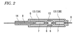
- Fig. 2 shows an arc tube for a discharge bulb.
- a lead support 2 that functions as a current path protruding toward the front side of an insulating base 1 and a grip member S that is fixed to the front surface of the insulating base 1 and is made of metal.
- the arc tube 5 is integrated with the insulating base 1.
- a quartz glass tube which has the shape of a cylindrical pipe, includes a spherical swelling portion that is formed in the middle of a linear extension portion in the longitudinal direction of the linear extension portion. Portions of the quartz glass tube, which are close to the spherical swelling portion, are pinch-sealed, so that an ellipsoidal sealed glass bulb 12 for forming a discharge space is formed.
- the arc tube 5 has a structure where pinch-sealed portions 13 (a primary pinch-sealed portion 13A and a secondary pinch-sealed portion 13B) having a rectangular cross-section are formed at both end portions of the ellipsoidal sealed glass bulb 12.
- a starting rare gas, mercury or a buffer material used instead of mercury, and a metal halide hereinafter, referred to as luminous materials and the like are sealed in the sealed glass bulb 12.
- electrode rods 6 and 6 which form discharge electrodes and are made of tungsten, are disposed in the sealed glass bulb 12 so as to face each other.
- the electrode rods 6 and 6 are connected to molybdenum foils 7 and 7 that are sealed in the pinch-sealed portions 13 and 13.
- Lead wires 8 and 8 which are made of molybdenum and connected to the molybdenum foils 7 and 7, are led from end portions of the pinch-sealed portions 13 and 13.
- the rear lead wire 8 extends to the outside through a cylindrical pipe-like portion 14 that is a portion not pinch-sealed.
- an electrode rod made of tungsten which is excellent in durability, is most preferable as the electrode rod 6.
- the coefficient of linear expansion of tungsten is significantly different from that of glass, and tungsten is incompatible with glass and has inferior airtightness.
- a shroud glass G for blocking ultraviolet light is integrated with the arc tube 5 by welding so that the region between the sealed glass bulb 12 and the pinch-sealed portions 13 is covered with the shroud glass G Accordingly, ultraviolet components, which correspond to a wavelength range harmful to a human body, of light emitted from the arc tube 5, are cut down, and the region between the sealed glass bulb 12 and the pinch-sealed portions 13 is surrounded by an enclosed space that is formed by the shroud glass G, so that a high temperature is maintained in the sealed glass bulb 12.
- an electrode assembly where the electrode rods 6, the molybdenum foils 7, and the lead wires 8 are integrally connected in series is prepared in advance and the electrode assembly is inserted into a quartz glass tube. Then, a region of the quartz glass tube, which includes the molybdenum foil 7 of the electrode assembly, is pinch-sealed, so that a primary pinch-sealed portion 13A is formed. After that, luminous materials and the like are injected into the sealed glass bulb 12, and the other end region of the quartz glass tube, which includes the molybdenum foil 7 of the electrode assembly, is pinch-sealed, so that a secondary pinch-sealed portion 13B is formed. Then, the luminous materials and the like are sealed.
- the external structure of the arc tube 5 shown in Figs. 1 and 2 is also not different from that of the well-known arc tube disclosed in JP-A-11-067153 and JP-A-2003-86136 .
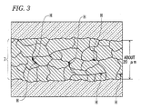
- the molybdenum foil 7 sealed in the pinch-sealed portion 13 is formed of recrystallized grains having an average grain size of about 3 to 5 ⁇ m and has a porous structure where closed cavities H are dispersed in a glass layer.
- the molybdenum foil 7 is made of molybdenum into which 0.5% of yttria (Y 2 O 3 ) is doped (added).
- a primary recrystallization treatment is performed first, so that the average grain size of the crystal grains of the molybdenum foil is changed to the range of about 1 to 1.5 ⁇ m from about 0.5 ⁇ m.
- pinch-sealing is performed by quartz glass (a secondary recrystallization treatment is performed at a pinch seal temperature of 2200 to 2300°C), so that the molybdenum foil 7 has a porous structure where the average grain size of the crystal grains is about 3 to 5 ⁇ m, a thickness is about 20 ⁇ m, and a plurality of cavities H is dispersed.
- the coefficient of linear expansion of the molybdenum foil 7 is different from that of quartz glass, stress is generated at the interface between the molybdenum foil 7 and quartz glass at the pinch-sealed portion 13 by the turning on/off of the arc tube 5.
- the porous structure of the molybdenum foil 7 relieves (reduces) the stress generated at the interface between the molybdenum foil 7 and quartz glass and suppresses the peeling off of molybdenum from glass, causing a sealing gas to leak at the pinch-sealed portion 13.
- the recrystallization of the molybdenum foil starts at a temperature of about 800 to about 1200°C.
- the quartz glass tube is to be pinch-sealed, the molybdenum foil is crushed while being exposed to a high temperature, which exceeds 2000°C, through quartz glass and the like. For this reason, the crystals of the molybdenum foil are recrystallized and roughened.
- voids (cavities) are not easily formed. If voids (cavities) are formed, the size of the voids (cavities) is excessively increased and the voids (cavities) reach the surface of the molybdenum foil. For this reason, closed cavities are not formed in the glass layer. As a result, a function of relieving (reducing) stress, which is generated at the interface between the molybdenum foil and quartz glass when the arc tube is turned on/off, is low.
- voids (cavities) to be formed in the molybdenum foil 7 are small if (the size of) the recrystallized grains of the pinch-sealed molybdenum foil 7 are excessively small, a function of relieving (reducing) stress, which is generated at the interface between the molybdenum foil 7 and quartz glass when the arc tube is turned on/off, is low.
- the average grain size of the crystal grains of the molybdenum foil 7 sealed in the pinch-sealed portion 13 be in a range of about 3 to 5 ⁇ m in order to make a plurality of closed cavities H be formed in the molybdenum foil 7 (to make the molybdenum foil 7 have a porous structure).
- the average grain size of the crystal grains of the molybdenum foil 7 sealed in the pinch-sealed portion 13 be in the range of about 3 to 5 ⁇ m
- a method of performing a reduction treatment at a temperature of about 900°C after performing an oxidation treatment at a temperature of about 500°C, a method of performing a vacuum heat treatment at a temperature of about 900°C, a method of performing a hydrogen treatment at a temperature of about 900°C, and the like are considered as the primary recrystallization treatment of the molybdenum foil 7.
- the primary recrystallization treatment is not limited to these methods.
- the molybdenum foil (whose crystal grain size is in the range of about 1 to 1.5 ⁇ m), which is primarily recrystallized by any one treatment of an oxidation (about 500°C)/reduction (about 900°C) treatment, a vacuum heat treatment (about 900°C), and a hydrogen treatment (about 900°C), is secondarily recrystallized (a crystal grain size is in the range of about 3 to 5 ⁇ m) by being exposed to the high temperature where the quartz glass tube is pinch-sealed.
- the pinch-sealed portion 13 having reached a high temperature is cooled, the contraction of the surface layer portion of the molybdenum foil 7 coming into close contact with the glass layer is suppressed by the glass layer but the inner portion of the molybdenum foil 7 can be freely contracted. For this reason, stress is generated between the crystal grains of the surface layer portion of the molybdenum foil and the crystal grains of the inner portion of the molybdenum foil, and the adjacent crystal grains are deviated from each other due to this stress. Accordingly, it is considered that voids are formed along boundaries of the crystal grains and a plurality of closed cavities H is formed in the molybdenum foil 7 due to the voids (the molybdenum foil has a porous structure).
- the pinch seal temperature of the quartz glass tube is 2230°C, a plurality of cavities is seen in the molybdenum foil.
- the pinch seal temperature of the quartz glass tube is 2150°C, a plurality of cavities is not seen in the molybdenum foil at all. Accordingly, in order to form cavities H in the molybdenum foil, it is preferable to set the pinch seal temperature to about 2200°C or more.
- the pinch seal temperature of the quartz glass tube is lower than about 2200°C, small stress is generated between the crystal grains of the surface layer portion of the molybdenum foil and the crystal grains of the inner portion of the molybdenum foil when the pinch-sealed portion, which has reached a high temperature due to pinch sealing, is cooled. For this reason, since adjacent crystal grains are not deviated from each other, it is considered that voids are not formed at the boundaries of the crystal grains (cavities H are not formed in the molybdenum foil).
- the pinch seal temperature of the quartz glass tube is preferably high.
- the pinch seal temperature of the quartz glass tube exceeds 2300°C, a burner and a pincher need to be made of a material excellent in heat resistance and large thermal energy used to heat quartz glass is also needled.
- a pinch seal temperature in order to form closed cavities H in a glass layer in the molybdenum foil 7 that is sealed in the pinch-sealed portion 13 (in order to make the molybdenum foil 7 have a porous structure), it is preferable to set a pinch seal temperature to the range of about 2200 to 2300°C.
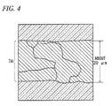
- the average grain size of the recrystallized crystal grains of a molybdenum foil 7A at a pinch-sealed portion is approximately in the range of about 20 to 30 ⁇ m which is larger than the thickness (about 20 ⁇ m) of the molybdenum foil and cavities are not seen in the molybdenum foil 7A at all.
- the average grain size of the crystal grains of the molybdenum foil is advantageous to adjust the average grain size of the crystal grains of the molybdenum foil to the range of about 1 to 1.5 ⁇ m by previously performing a primary recrystallization treatment on the molybdenum foil that is not yet pinch-sealed.
- the porous structure of the molybdenum foil 7 at the pinch-sealed portion 13 relieves (reduces) the stress generated at the interface between the molybdenum foil 7 and quartz glass and suppresses the peeling off of molybdenum from glass, causing a sealing gas to leak at the pinch-sealed portion 13. Accordingly, the long life of the arc tube is ensured as shown in Fig. 5 .
- the molybdenum foil 7 is primarily recrystallized, so that fine irregularities are formed on the surface of the molybdenum foil 7.
- a surface etching treatment using oxidation (500°C) and reduction (900°C) is employed as the primary recrystallization treatment of the molybdenum foil 7, an oxide film is formed on the surface of an oxidized molybdenum foil and oxygen atoms are removed from the oxide film by a reduction treatment.
- Fig. 5 is a view comparing data of life tests of the arc tubes (first, second, and third examples), which use molybdenum foils subjected to an oxidation/reduction treatment, a vacuum heat treatment, and a hydrogen treatment as a primary recrystallization treatment, with data of a life test of the arc tube (comparative example) that uses a molybdenum foil not subjected to a primary recrystallization treatment.
- an arc tube (first example) using a molybdenum foil subjected to an oxidation/reduction treatment as a primary recrystallization treatment is the most excellent among the first to third examples, even from the data of life tests, that is, from the fact that the average life of an arc tube is 2697 hours when an oxidation/reduction treatment is employed as a primary recrystallization treatment, the average life of an arc tube is 2399 hours when a vacuum heat treatment is employed as a primary recrystallization treatment, and the average life of an arc tube is 2418 hours when a hydrogen treatment is employed as a primary recrystallization treatment.
Landscapes
- Engineering & Computer Science (AREA)
- Manufacturing & Machinery (AREA)
- Vessels And Coating Films For Discharge Lamps (AREA)
Abstract
Description
- The present disclosure relates to an arc tube for discharge bulb, including a sealed glass bulb where electrodes are provided in a sealed glass bulb so as to face each other and luminous materials are enclosed.
- In an arc tube disclosed in
JP-A-11-067153 JP-A-2003-86136 JP-A-11-067153 JP-A-2003-86136 - In
JP-A-11-067153 - In
JP-A-2003-86136 - In the disclosure of
JP-A-11-067153 JP-A-2003-86136 JP-A-11-067153 JP-A-2003-86136 - That is, it was possible to obtain a result that the separation between glass and the molybdenum foil is suppressed even though the surface of the molybdenum foil at the pinch-sealed portion does not have an extremely roughened surface structure for increasing the adhesion (mechanical bond strength) between the molybdenum foil and glass.
- Accordingly, the inventor carefully observed the cross-section of the molybdenum foil of this prototype in order to look into this cause. As a result, a plurality of closed cavities, which had not been seen in a comparative example (an arc tube using a molybdenum foil that is not subjected to a primary recrystallization treatment) at all, was seen in the molybdenum foil. That is, closed cavities (cavities reliably separated from a glass layer) are formed in the molybdenum foil at the pinch-sealed portion. Accordingly, it is confirmed that the cavities (a porous structure of the molybdenum foil including a plurality of closed cavities) reduce stress generated at the interface between the molybdenum foil and quartz glass when the arc tube is turned on/off and are advantageous in suppressing the occurrence of the peeling off of molybdenum from glass.
- In addition, even in the case of the arc tube of
JP-A-2003-86136 - Exemplary embodiments of the present invention may address the above disadvantages and other disadvantages not described above. However, the present invention is not required to overcome the disadvantages described above, and thus, an exemplary embodiment of the present invention may not overcome any disadvantages.
- In an illustrative aspect of the present invention may provide an arc tube for a discharge bulb whose life is lengthened through the suppression of the peeling off of molybdenum from glass.
- According to one or more aspects of the present invention, an arc tube for a discharge bulb, comprising a sealed glass bulb in which luminous materials are sealed; a plurality of pinch-sealed portions made of quartz glass and formed at both end portions of the sealed glass bulb; a plurality of molybdenum foils each pinch sealed in the corresponding pinch-sealed portion; a pair of electrode rods provided in the sealed glass bulb so as to face each other, wherein each of electrode rods extends from the sealed glass bulb to the corresponding pinch-sealed portion and is connected to one end of the corresponding molybdenum foil; and a plurality of lead wires each connected to the other end of the corresponding molybdenum foil, wherein the molybdenum foils comprise a plurality of closed cavities therein.
- Other aspects and advantages of the present invention will be apparent from the following description, the drawings and the claims.
-
-
Fig. 1 is a longitudinal sectional view of the entire discharge bulb including an arc tube according to an embodiment; -
Fig. 2 is a horizontal sectional view of the arc tube according to the embodiment; -
Fig. 3 is an enlarged sectional view of a molybdenum foil that is sealed in a pinch-sealed portion of the arc tube according to the embodiment; -
Fig. 4 is an enlarged sectional view of a molybdenum foil (a molybdenum foil that is not subjected to a primary recrystallization treatment) that is sealed in a pinch-sealed portion of an arc tube according to a comparative example; and -
Fig. 5 is a view comparing data of life tests of the arc tubes (examples), which use molybdenum foils subjected to a primary recrystallization treatment (an oxidation/reduction treatment, a vacuum heat treatment, and a hydrogen treatment), with data of a life test of the arc tube (comparative example) that uses a molybdenum foil not subjected to a primary recrystallization treatment. - An embodiment of the invention will be described below with reference to examples.
-
Figs. 1 and2 show an example where the invention is applied to a discharge bulb widely used as a light source of a vehicle headlamp.Fig. 1 shows the entire discharge bulb, andFig. 2 shows an arc tube for a discharge bulb. - As shown in
Fig. 1 , front and rear end portions of anarc tube 5 of a discharge bulb are supported by alead support 2 that functions as a current path protruding toward the front side of aninsulating base 1 and a grip member S that is fixed to the front surface of theinsulating base 1 and is made of metal. Thearc tube 5 is integrated with theinsulating base 1. - A quartz glass tube, which has the shape of a cylindrical pipe, includes a spherical swelling portion that is formed in the middle of a linear extension portion in the longitudinal direction of the linear extension portion. Portions of the quartz glass tube, which are close to the spherical swelling portion, are pinch-sealed, so that an ellipsoidal sealed
glass bulb 12 for forming a discharge space is formed. Thearc tube 5 has a structure where pinch-sealed portions 13 (a primary pinch-sealedportion 13A and a secondary pinch-sealedportion 13B) having a rectangular cross-section are formed at both end portions of the ellipsoidal sealedglass bulb 12. A starting rare gas, mercury or a buffer material used instead of mercury, and a metal halide (hereinafter, referred to as luminous materials and the like) are sealed in the sealedglass bulb 12. - Further,
electrode rods glass bulb 12 so as to face each other. Theelectrode rods molybdenum foils portions Lead wires molybdenum foils portions rear lead wire 8 extends to the outside through a cylindrical pipe-like portion 14 that is a portion not pinch-sealed. - That is, an electrode rod made of tungsten, which is excellent in durability, is most preferable as the
electrode rod 6. However, the coefficient of linear expansion of tungsten is significantly different from that of glass, and tungsten is incompatible with glass and has inferior airtightness. For this reason, themolybdenum foil 7, whose coefficient of linear expansion is close to that of glass and which is relatively compatible with glass, is connected to theelectrode rod 6 made of tungsten and themolybdenum foil 7 is sealed in the pinch-sealedportion 13, so that airtightness is secured at the pinch-sealedportion 13. - Further, a shroud glass G for blocking ultraviolet light is integrated with the
arc tube 5 by welding so that the region between the sealedglass bulb 12 and the pinch-sealedportions 13 is covered with the shroud glass G Accordingly, ultraviolet components, which correspond to a wavelength range harmful to a human body, of light emitted from thearc tube 5, are cut down, and the region between the sealedglass bulb 12 and the pinch-sealedportions 13 is surrounded by an enclosed space that is formed by the shroud glass G, so that a high temperature is maintained in the sealedglass bulb 12. - Furthermore, in manufacturing the
arc tube 5, an electrode assembly where the electrode rods 6, themolybdenum foils 7, and thelead wires 8 are integrally connected in series is prepared in advance and the electrode assembly is inserted into a quartz glass tube. Then, a region of the quartz glass tube, which includes themolybdenum foil 7 of the electrode assembly, is pinch-sealed, so that a primary pinch-sealedportion 13A is formed. After that, luminous materials and the like are injected into the sealedglass bulb 12, and the other end region of the quartz glass tube, which includes themolybdenum foil 7 of the electrode assembly, is pinch-sealed, so that a secondary pinch-sealedportion 13B is formed. Then, the luminous materials and the like are sealed. - Since a process for manufacturing the
arc tube 5 is disclosed in detail inJP-A-2003-86136 - The external structure of the
arc tube 5 shown inFigs. 1 and 2 is also not different from that of the well-known arc tube disclosed inJP-A-11-067153 JP-A-2003-86136 Fig. 3 , themolybdenum foil 7 sealed in the pinch-sealedportion 13 is formed of recrystallized grains having an average grain size of about 3 to 5 µm and has a porous structure where closed cavities H are dispersed in a glass layer. Accordingly, stress, which is generated at the interface between themolybdenum foil 7 and quartz glass by the turning on/off of thearc tube 5, is relieved (reduced) by the porous structure of themolybdenum foil 7, so that the peeling off of molybdenum from glass, causing sealing gas to leak at the pinch-sealedportion 13, is suppressed. - That is, the
molybdenum foil 7 is made of molybdenum into which 0.5% of yttria (Y2O3) is doped (added). However, a primary recrystallization treatment is performed first, so that the average grain size of the crystal grains of the molybdenum foil is changed to the range of about 1 to 1.5 µm from about 0.5 µm. Further, pinch-sealing is performed by quartz glass (a secondary recrystallization treatment is performed at a pinch seal temperature of 2200 to 2300°C), so that themolybdenum foil 7 has a porous structure where the average grain size of the crystal grains is about 3 to 5 µm, a thickness is about 20 µm, and a plurality of cavities H is dispersed. - In detail, since the coefficient of linear expansion of the
molybdenum foil 7 is different from that of quartz glass, stress is generated at the interface between themolybdenum foil 7 and quartz glass at the pinch-sealedportion 13 by the turning on/off of thearc tube 5. However, the porous structure of the molybdenum foil 7 (cavities formed in the molybdenum foil) relieves (reduces) the stress generated at the interface between themolybdenum foil 7 and quartz glass and suppresses the peeling off of molybdenum from glass, causing a sealing gas to leak at the pinch-sealedportion 13. - Meanwhile, the recrystallization of the molybdenum foil starts at a temperature of about 800 to about 1200°C. However, when the quartz glass tube is to be pinch-sealed, the molybdenum foil is crushed while being exposed to a high temperature, which exceeds 2000°C, through quartz glass and the like. For this reason, the crystals of the molybdenum foil are recrystallized and roughened.
- Further, since the number of grain boundaries of the crystals is small if (the size of) the recrystallized grains of the pinch-sealed
molybdenum foil 7 are excessively large, voids (cavities) are not easily formed. If voids (cavities) are formed, the size of the voids (cavities) is excessively increased and the voids (cavities) reach the surface of the molybdenum foil. For this reason, closed cavities are not formed in the glass layer. As a result, a function of relieving (reducing) stress, which is generated at the interface between the molybdenum foil and quartz glass when the arc tube is turned on/off, is low. Meanwhile, since voids (cavities) to be formed in themolybdenum foil 7 are small if (the size of) the recrystallized grains of the pinch-sealedmolybdenum foil 7 are excessively small, a function of relieving (reducing) stress, which is generated at the interface between themolybdenum foil 7 and quartz glass when the arc tube is turned on/off, is low. - Moreover, as a result of the consideration of the cross-sectional structure of a prototype, it is advantageous that the average grain size of the crystal grains of the
molybdenum foil 7 sealed in the pinch-sealedportion 13 be in a range of about 3 to 5 µm in order to make a plurality of closed cavities H be formed in the molybdenum foil 7 (to make themolybdenum foil 7 have a porous structure). - In addition, in order to make the average grain size of the crystal grains of the
molybdenum foil 7 sealed in the pinch-sealedportion 13 be in the range of about 3 to 5 µm, it is advantageous to adjust the average grain size of the crystal grains of the molybdenum foil to the range of about 1 to about 1.5 µm by performing a primary recrystallization treatment on the molybdenum foil that is not yet pinch-sealed. - Meanwhile, for example, a method of performing a reduction treatment at a temperature of about 900°C after performing an oxidation treatment at a temperature of about 500°C, a method of performing a vacuum heat treatment at a temperature of about 900°C, a method of performing a hydrogen treatment at a temperature of about 900°C, and the like are considered as the primary recrystallization treatment of the
molybdenum foil 7. However, as long as the size (average grain size) of the crystal grains of themolybdenum foil 7 can be changed to the range of about 1 to 1.5 µm from about 0.5 µm, the primary recrystallization treatment is not limited to these methods. - Next, there will be described a mechanism for forming closed cavities in a glass layer in the
molybdenum foil 7 that is sealed in the pinch-sealed portion 13 (a mechanism for making themolybdenum foil 7 have a porous structure). - Since a temperature where a quartz glass tube is pinch-sealed is set to be high (about 2200 to 2300°C) in the range of a general pinch seal temperature (about 2000 to 2300°C) which is well-known in the related art JO-73), the molybdenum foil (whose crystal grain size is in the range of about 1 to 1.5 µm), which is primarily recrystallized by any one treatment of an oxidation (about 500°C)/reduction (about 900°C) treatment, a vacuum heat treatment (about 900°C), and a hydrogen treatment (about 900°C), is secondarily recrystallized (a crystal grain size is in the range of about 3 to 5 µm) by being exposed to the high temperature where the quartz glass tube is pinch-sealed. However, parts of the recrystallized crystal grains are deviated from each other and voids are formed between the crystal grains due to the internal stress that is generated while all the recrystallized crystal grains (whose crystal grain size is in the range of about 3 to 5 µm) are contracted (cooled) after being thermally expanded. Accordingly, it is considered that these voids form a plurality of closed cavities in the molybdenum foil 7 (the molybdenum foil has a porous structure).
- In detail, when the pinch-sealed
portion 13 having reached a high temperature is cooled, the contraction of the surface layer portion of themolybdenum foil 7 coming into close contact with the glass layer is suppressed by the glass layer but the inner portion of themolybdenum foil 7 can be freely contracted. For this reason, stress is generated between the crystal grains of the surface layer portion of the molybdenum foil and the crystal grains of the inner portion of the molybdenum foil, and the adjacent crystal grains are deviated from each other due to this stress. Accordingly, it is considered that voids are formed along boundaries of the crystal grains and a plurality of closed cavities H is formed in themolybdenum foil 7 due to the voids (the molybdenum foil has a porous structure). - Meanwhile, if the pinch seal temperature of the quartz glass tube is 2230°C, a plurality of cavities is seen in the molybdenum foil. However, if the pinch seal temperature of the quartz glass tube is 2150°C, a plurality of cavities is not seen in the molybdenum foil at all. Accordingly, in order to form cavities H in the molybdenum foil, it is preferable to set the pinch seal temperature to about 2200°C or more. That is, if the pinch seal temperature of the quartz glass tube is lower than about 2200°C, small stress is generated between the crystal grains of the surface layer portion of the molybdenum foil and the crystal grains of the inner portion of the molybdenum foil when the pinch-sealed portion, which has reached a high temperature due to pinch sealing, is cooled. For this reason, since adjacent crystal grains are not deviated from each other, it is considered that voids are not formed at the boundaries of the crystal grains (cavities H are not formed in the molybdenum foil).
- Meanwhile, if the pinch seal temperature of the quartz glass tube is high, the stress generated between the crystal grains of the surface layer portion of the molybdenum foil and the crystal grains of the inner portion of the molybdenum foil is large. Accordingly, the deviation between adjacent crystal grains is large, so that a plurality of large voids can be formed at the boundaries of the crystal grains (many cavities H are formed in the molybdenum foil). Therefore, the pinch seal temperature of the quartz glass tube is preferably high. However, if the pinch seal temperature of the quartz glass tube exceeds 2300°C, a burner and a pincher need to be made of a material excellent in heat resistance and large thermal energy used to heat quartz glass is also needled.
- Accordingly, in order to form closed cavities H in a glass layer in the
molybdenum foil 7 that is sealed in the pinch-sealed portion 13 (in order to make themolybdenum foil 7 have a porous structure), it is preferable to set a pinch seal temperature to the range of about 2200 to 2300°C. - Further, in an arc tube (comparative example) that is pinch-sealed using a molybdenum foil (whose average grain size of crystal grains is about 0.5 µm) not subjected to a primary recrystallization treatment, as shown in
Fig. 4 , the average grain size of the recrystallized crystal grains of amolybdenum foil 7A at a pinch-sealed portion is approximately in the range of about 20 to 30 µm which is larger than the thickness (about 20 µm) of the molybdenum foil and cavities are not seen in themolybdenum foil 7A at all. Accordingly, in order to form closed cavities H in themolybdenum foil 7A at the pinch-sealed portion 13 (in order to make themolybdenum foil 7A have a porous structure), it is advantageous to adjust the average grain size of the crystal grains of the molybdenum foil to the range of about 1 to 1.5 µm by previously performing a primary recrystallization treatment on the molybdenum foil that is not yet pinch-sealed. - Furthermore, in the
arc tube 5 according to this example, the porous structure of themolybdenum foil 7 at the pinch-sealed portion 13 (the cavities H formed in the molybdenum foil 7) relieves (reduces) the stress generated at the interface between themolybdenum foil 7 and quartz glass and suppresses the peeling off of molybdenum from glass, causing a sealing gas to leak at the pinch-sealedportion 13. Accordingly, the long life of the arc tube is ensured as shown inFig. 5 . - Moreover, the
molybdenum foil 7 is primarily recrystallized, so that fine irregularities are formed on the surface of themolybdenum foil 7. In particular, if a surface etching treatment using oxidation (500°C) and reduction (900°C) is employed as the primary recrystallization treatment of themolybdenum foil 7, an oxide film is formed on the surface of an oxidized molybdenum foil and oxygen atoms are removed from the oxide film by a reduction treatment. Accordingly, a rough surface (etched surface) having the shape of fine irregularities, which are deeper and more complicated than fine irregularities formed on the surface of the oxidized molybdenum foil, is formed on the surface of the molybdenum foil. Therefore, the adhesion, that is, mechanical bond strength at the interface between quartz glass and the molybdenum foil is also improved. As a result, the separation between glass and the molybdenum foil is further suppressed. -
Fig. 5 is a view comparing data of life tests of the arc tubes (first, second, and third examples), which use molybdenum foils subjected to an oxidation/reduction treatment, a vacuum heat treatment, and a hydrogen treatment as a primary recrystallization treatment, with data of a life test of the arc tube (comparative example) that uses a molybdenum foil not subjected to a primary recrystallization treatment. However, it was found that an arc tube (first example) using a molybdenum foil subjected to an oxidation/reduction treatment as a primary recrystallization treatment is the most excellent among the first to third examples, even from the data of life tests, that is, from the fact that the average life of an arc tube is 2697 hours when an oxidation/reduction treatment is employed as a primary recrystallization treatment, the average life of an arc tube is 2399 hours when a vacuum heat treatment is employed as a primary recrystallization treatment, and the average life of an arc tube is 2418 hours when a hydrogen treatment is employed as a primary recrystallization treatment. - While aspects of embodiments of the present invention have been shown and described above, other implementations are within the scope of the claims. It will be understood by those skilled in the art that various changes in form and details may be made therein without departing from the spirit and scope of the invention as defined by the appended claims.
Claims (5)
- An arc tube for a discharge bulb, comprising
a sealed glass bulb in which luminous materials are sealed;
a plurality of pinch-sealed portions made of quartz glass and formed at both end portions of the sealed glass bulb;
a plurality of molybdenum foils each pinch sealed in the corresponding pinch-sealed portion;
a pair of electrode rods provided in the sealed glass bulb so as to face each other, wherein each of electrode rods extends from the sealed glass bulb to the corresponding pinch-sealed portion and is connected to one end of the corresponding molybdenum foil; and
a plurality of lead wires each connected to the other end of the corresponding molybdenum foil,
wherein the molybdenum foils comprise a plurality of closed cavities therein. - The arc tube according to claim 1, wherein an average grain size of crystal grains of the molybdenum foil is in the range of about 3 to 5 µm.
- The arc tube according to claim 1 or 2, wherein the molybdenum foils are subjected to any one treatment of an oxidation/reduction treatment, a vacuum heat treatment, and a hydrogen treatment, prior to being pinch sealed so that an average grain size of crystal grains of the molybdenum foil is in the range of about 1 to 1.5 µm.
- The arc tube according to one of the proceeding claims, wherein the molybdenum foil is doped with .5% yttria (Y2O3).
- The arc tube according to one of the proceeding claims, wherein the pinched-sealed portions are formed at a temperature equal to or greater than 2200°C and less than or equal to 2300°C.
Applications Claiming Priority (1)
| Application Number | Priority Date | Filing Date | Title |
|---|---|---|---|
| JP2010093952A JP5495381B2 (en) | 2010-04-15 | 2010-04-15 | Arc tube for discharge bulb |
Publications (3)
| Publication Number | Publication Date |
|---|---|
| EP2378541A2 true EP2378541A2 (en) | 2011-10-19 |
| EP2378541A3 EP2378541A3 (en) | 2013-11-06 |
| EP2378541B1 EP2378541B1 (en) | 2015-08-12 |
Family
ID=44201933
Family Applications (1)
| Application Number | Title | Priority Date | Filing Date |
|---|---|---|---|
| EP11162032.4A Not-in-force EP2378541B1 (en) | 2010-04-15 | 2011-04-12 | Manufacture of an arc tube with improved pinch seals |
Country Status (3)
| Country | Link |
|---|---|
| US (1) | US8330369B2 (en) |
| EP (1) | EP2378541B1 (en) |
| JP (1) | JP5495381B2 (en) |
Citations (4)
| Publication number | Priority date | Publication date | Assignee | Title |
|---|---|---|---|---|
| JPS6467153A (en) | 1987-09-08 | 1989-03-13 | Mitsubishi Chem Ind | Production of protein textured food |
| JPH067153A (en) | 1992-01-29 | 1994-01-18 | Phillips Petroleum Co | Processing of Phaffia Roadzyma |
| JPH1167153A (en) | 1997-08-21 | 1999-03-09 | Koito Mfg Co Ltd | Metal halide lamp |
| JP2003086136A (en) | 2001-09-07 | 2003-03-20 | Koito Mfg Co Ltd | Discharge lamp arc tube and method of manufacturing arc tube |
Family Cites Families (4)
| Publication number | Priority date | Publication date | Assignee | Title |
|---|---|---|---|---|
| US419602A (en) * | 1890-01-14 | Street-car and other advertising device | ||
| GB1401545A (en) * | 1972-10-06 | 1975-07-16 | Lamp Metals Ltd | Manufacture of thin metal bodies |
| AT4408U1 (en) * | 2000-05-18 | 2001-06-25 | Plansee Ag | METHOD FOR PRODUCING AN ELECTRIC LAMP |
| JP4509754B2 (en) * | 2004-12-02 | 2010-07-21 | 株式会社小糸製作所 | Arc tube for discharge lamp device and method of manufacturing the same |
-
2010
- 2010-04-15 JP JP2010093952A patent/JP5495381B2/en not_active Expired - Fee Related
-
2011
- 2011-04-12 EP EP11162032.4A patent/EP2378541B1/en not_active Not-in-force
- 2011-04-13 US US13/085,548 patent/US8330369B2/en not_active Expired - Fee Related
Patent Citations (4)
| Publication number | Priority date | Publication date | Assignee | Title |
|---|---|---|---|---|
| JPS6467153A (en) | 1987-09-08 | 1989-03-13 | Mitsubishi Chem Ind | Production of protein textured food |
| JPH067153A (en) | 1992-01-29 | 1994-01-18 | Phillips Petroleum Co | Processing of Phaffia Roadzyma |
| JPH1167153A (en) | 1997-08-21 | 1999-03-09 | Koito Mfg Co Ltd | Metal halide lamp |
| JP2003086136A (en) | 2001-09-07 | 2003-03-20 | Koito Mfg Co Ltd | Discharge lamp arc tube and method of manufacturing arc tube |
Also Published As
| Publication number | Publication date |
|---|---|
| JP5495381B2 (en) | 2014-05-21 |
| JP2011228011A (en) | 2011-11-10 |
| US20110254438A1 (en) | 2011-10-20 |
| EP2378541B1 (en) | 2015-08-12 |
| EP2378541A3 (en) | 2013-11-06 |
| US8330369B2 (en) | 2012-12-11 |
Similar Documents
| Publication | Publication Date | Title |
|---|---|---|
| US6918808B2 (en) | Arc tube for discharge lamp and method for producing the same | |
| JP4681668B2 (en) | Foil seal lamp | |
| JPH1196973A (en) | High pressure discharge lamp and lighting equipment | |
| US8330369B2 (en) | Arc tube for discharge bulb | |
| EP2748833B1 (en) | High-pressure gas discharge lamp | |
| JP2008192475A (en) | High-pressure discharge lamp | |
| JP4231380B2 (en) | Light bulb and current conductor used therefor | |
| JP2007134055A (en) | Arc tube for discharge lamp apparatus | |
| KR20110044695A (en) | Excimer lamp | |
| JPH1167153A (en) | Metal halide lamp | |
| JP2009032446A (en) | High pressure discharge lamp | |
| EP2476133B1 (en) | High intensity discharge lamp | |
| JP4606281B2 (en) | Arc tube for discharge lamp equipment | |
| US8148902B2 (en) | Mercury-free arc tube for discharge lamp device and method for manufacturing the same | |
| JP4799132B2 (en) | Arc tube for discharge lamp equipment | |
| JP2005183164A (en) | Arc tube for discharge lamp apparatus | |
| JP2000294196A (en) | High-pressure discharge lamp | |
| US9401269B2 (en) | Socket and discharge lamp | |
| JP4719105B2 (en) | Metal halide lamp | |
| JP4294687B2 (en) | Electric discharge lamp | |
| JP3385810B2 (en) | Metal halide lamp | |
| JP3480454B2 (en) | Short arc type ultra-high pressure discharge lamp | |
| JP2001243911A (en) | High pressure discharge lamp and lighting equipment | |
| JP3405001B2 (en) | Metal halide lamp | |
| JPH08264159A (en) | Ceramic discharge lamp, its lighting device, and lighting device using the same |
Legal Events
| Date | Code | Title | Description |
|---|---|---|---|
| 17P | Request for examination filed |
Effective date: 20110412 |
|
| AK | Designated contracting states |
Kind code of ref document: A2 Designated state(s): AL AT BE BG CH CY CZ DE DK EE ES FI FR GB GR HR HU IE IS IT LI LT LU LV MC MK MT NL NO PL PT RO RS SE SI SK SM TR |
|
| AX | Request for extension of the european patent |
Extension state: BA ME |
|
| PUAI | Public reference made under article 153(3) epc to a published international application that has entered the european phase |
Free format text: ORIGINAL CODE: 0009012 |
|
| PUAL | Search report despatched |
Free format text: ORIGINAL CODE: 0009013 |
|
| AK | Designated contracting states |
Kind code of ref document: A3 Designated state(s): AL AT BE BG CH CY CZ DE DK EE ES FI FR GB GR HR HU IE IS IT LI LT LU LV MC MK MT NL NO PL PT RO RS SE SI SK SM TR |
|
| AX | Request for extension of the european patent |
Extension state: BA ME |
|
| RIC1 | Information provided on ipc code assigned before grant |
Ipc: H01J 9/32 20060101ALI20130930BHEP Ipc: H01J 61/36 20060101AFI20130930BHEP |
|
| 17Q | First examination report despatched |
Effective date: 20140513 |
|
| GRAP | Despatch of communication of intention to grant a patent |
Free format text: ORIGINAL CODE: EPIDOSNIGR1 |
|
| INTG | Intention to grant announced |
Effective date: 20150319 |
|
| GRAS | Grant fee paid |
Free format text: ORIGINAL CODE: EPIDOSNIGR3 |
|
| GRAA | (expected) grant |
Free format text: ORIGINAL CODE: 0009210 |
|
| AK | Designated contracting states |
Kind code of ref document: B1 Designated state(s): AL AT BE BG CH CY CZ DE DK EE ES FI FR GB GR HR HU IE IS IT LI LT LU LV MC MK MT NL NO PL PT RO RS SE SI SK SM TR |
|
| REG | Reference to a national code |
Ref country code: GB Ref legal event code: FG4D |
|
| REG | Reference to a national code |
Ref country code: CH Ref legal event code: EP |
|
| REG | Reference to a national code |
Ref country code: AT Ref legal event code: REF Ref document number: 742799 Country of ref document: AT Kind code of ref document: T Effective date: 20150815 |
|
| REG | Reference to a national code |
Ref country code: IE Ref legal event code: FG4D |
|
| REG | Reference to a national code |
Ref country code: DE Ref legal event code: R096 Ref document number: 602011018594 Country of ref document: DE |
|
| REG | Reference to a national code |
Ref country code: LT Ref legal event code: MG4D |
|
| REG | Reference to a national code |
Ref country code: AT Ref legal event code: MK05 Ref document number: 742799 Country of ref document: AT Kind code of ref document: T Effective date: 20150812 |
|
| REG | Reference to a national code |
Ref country code: NL Ref legal event code: MP Effective date: 20150812 |
|
| PG25 | Lapsed in a contracting state [announced via postgrant information from national office to epo] |
Ref country code: LV Free format text: LAPSE BECAUSE OF FAILURE TO SUBMIT A TRANSLATION OF THE DESCRIPTION OR TO PAY THE FEE WITHIN THE PRESCRIBED TIME-LIMIT Effective date: 20150812 Ref country code: LT Free format text: LAPSE BECAUSE OF FAILURE TO SUBMIT A TRANSLATION OF THE DESCRIPTION OR TO PAY THE FEE WITHIN THE PRESCRIBED TIME-LIMIT Effective date: 20150812 Ref country code: FI Free format text: LAPSE BECAUSE OF FAILURE TO SUBMIT A TRANSLATION OF THE DESCRIPTION OR TO PAY THE FEE WITHIN THE PRESCRIBED TIME-LIMIT Effective date: 20150812 Ref country code: NO Free format text: LAPSE BECAUSE OF FAILURE TO SUBMIT A TRANSLATION OF THE DESCRIPTION OR TO PAY THE FEE WITHIN THE PRESCRIBED TIME-LIMIT Effective date: 20151112 Ref country code: GR Free format text: LAPSE BECAUSE OF FAILURE TO SUBMIT A TRANSLATION OF THE DESCRIPTION OR TO PAY THE FEE WITHIN THE PRESCRIBED TIME-LIMIT Effective date: 20151113 |
|
| PG25 | Lapsed in a contracting state [announced via postgrant information from national office to epo] |
Ref country code: IS Free format text: LAPSE BECAUSE OF FAILURE TO SUBMIT A TRANSLATION OF THE DESCRIPTION OR TO PAY THE FEE WITHIN THE PRESCRIBED TIME-LIMIT Effective date: 20151212 Ref country code: HR Free format text: LAPSE BECAUSE OF FAILURE TO SUBMIT A TRANSLATION OF THE DESCRIPTION OR TO PAY THE FEE WITHIN THE PRESCRIBED TIME-LIMIT Effective date: 20150812 Ref country code: ES Free format text: LAPSE BECAUSE OF FAILURE TO SUBMIT A TRANSLATION OF THE DESCRIPTION OR TO PAY THE FEE WITHIN THE PRESCRIBED TIME-LIMIT Effective date: 20150812 Ref country code: AT Free format text: LAPSE BECAUSE OF FAILURE TO SUBMIT A TRANSLATION OF THE DESCRIPTION OR TO PAY THE FEE WITHIN THE PRESCRIBED TIME-LIMIT Effective date: 20150812 Ref country code: RS Free format text: LAPSE BECAUSE OF FAILURE TO SUBMIT A TRANSLATION OF THE DESCRIPTION OR TO PAY THE FEE WITHIN THE PRESCRIBED TIME-LIMIT Effective date: 20150812 Ref country code: PT Free format text: LAPSE BECAUSE OF FAILURE TO SUBMIT A TRANSLATION OF THE DESCRIPTION OR TO PAY THE FEE WITHIN THE PRESCRIBED TIME-LIMIT Effective date: 20151214 Ref country code: SE Free format text: LAPSE BECAUSE OF FAILURE TO SUBMIT A TRANSLATION OF THE DESCRIPTION OR TO PAY THE FEE WITHIN THE PRESCRIBED TIME-LIMIT Effective date: 20150812 Ref country code: PL Free format text: LAPSE BECAUSE OF FAILURE TO SUBMIT A TRANSLATION OF THE DESCRIPTION OR TO PAY THE FEE WITHIN THE PRESCRIBED TIME-LIMIT Effective date: 20150812 |
|
| REG | Reference to a national code |
Ref country code: FR Ref legal event code: PLFP Year of fee payment: 6 |
|
| PG25 | Lapsed in a contracting state [announced via postgrant information from national office to epo] |
Ref country code: NL Free format text: LAPSE BECAUSE OF FAILURE TO SUBMIT A TRANSLATION OF THE DESCRIPTION OR TO PAY THE FEE WITHIN THE PRESCRIBED TIME-LIMIT Effective date: 20150812 |
|
| PG25 | Lapsed in a contracting state [announced via postgrant information from national office to epo] |
Ref country code: IT Free format text: LAPSE BECAUSE OF FAILURE TO SUBMIT A TRANSLATION OF THE DESCRIPTION OR TO PAY THE FEE WITHIN THE PRESCRIBED TIME-LIMIT Effective date: 20150812 Ref country code: CZ Free format text: LAPSE BECAUSE OF FAILURE TO SUBMIT A TRANSLATION OF THE DESCRIPTION OR TO PAY THE FEE WITHIN THE PRESCRIBED TIME-LIMIT Effective date: 20150812 Ref country code: DK Free format text: LAPSE BECAUSE OF FAILURE TO SUBMIT A TRANSLATION OF THE DESCRIPTION OR TO PAY THE FEE WITHIN THE PRESCRIBED TIME-LIMIT Effective date: 20150812 Ref country code: SK Free format text: LAPSE BECAUSE OF FAILURE TO SUBMIT A TRANSLATION OF THE DESCRIPTION OR TO PAY THE FEE WITHIN THE PRESCRIBED TIME-LIMIT Effective date: 20150812 Ref country code: EE Free format text: LAPSE BECAUSE OF FAILURE TO SUBMIT A TRANSLATION OF THE DESCRIPTION OR TO PAY THE FEE WITHIN THE PRESCRIBED TIME-LIMIT Effective date: 20150812 |
|
| REG | Reference to a national code |
Ref country code: DE Ref legal event code: R097 Ref document number: 602011018594 Country of ref document: DE |
|
| PG25 | Lapsed in a contracting state [announced via postgrant information from national office to epo] |
Ref country code: RO Free format text: LAPSE BECAUSE OF FAILURE TO SUBMIT A TRANSLATION OF THE DESCRIPTION OR TO PAY THE FEE WITHIN THE PRESCRIBED TIME-LIMIT Effective date: 20150812 |
|
| PLBE | No opposition filed within time limit |
Free format text: ORIGINAL CODE: 0009261 |
|
| STAA | Information on the status of an ep patent application or granted ep patent |
Free format text: STATUS: NO OPPOSITION FILED WITHIN TIME LIMIT |
|
| 26N | No opposition filed |
Effective date: 20160513 |
|
| PGFP | Annual fee paid to national office [announced via postgrant information from national office to epo] |
Ref country code: GB Payment date: 20160406 Year of fee payment: 6 |
|
| PG25 | Lapsed in a contracting state [announced via postgrant information from national office to epo] |
Ref country code: SI Free format text: LAPSE BECAUSE OF FAILURE TO SUBMIT A TRANSLATION OF THE DESCRIPTION OR TO PAY THE FEE WITHIN THE PRESCRIBED TIME-LIMIT Effective date: 20150812 Ref country code: BE Free format text: LAPSE BECAUSE OF NON-PAYMENT OF DUE FEES Effective date: 20160430 |
|
| REG | Reference to a national code |
Ref country code: CH Ref legal event code: PL |
|
| PG25 | Lapsed in a contracting state [announced via postgrant information from national office to epo] |
Ref country code: BE Free format text: LAPSE BECAUSE OF FAILURE TO SUBMIT A TRANSLATION OF THE DESCRIPTION OR TO PAY THE FEE WITHIN THE PRESCRIBED TIME-LIMIT Effective date: 20150812 Ref country code: LU Free format text: LAPSE BECAUSE OF FAILURE TO SUBMIT A TRANSLATION OF THE DESCRIPTION OR TO PAY THE FEE WITHIN THE PRESCRIBED TIME-LIMIT Effective date: 20160412 |
|
| REG | Reference to a national code |
Ref country code: IE Ref legal event code: MM4A |
|
| PG25 | Lapsed in a contracting state [announced via postgrant information from national office to epo] |
Ref country code: CH Free format text: LAPSE BECAUSE OF NON-PAYMENT OF DUE FEES Effective date: 20160430 Ref country code: LI Free format text: LAPSE BECAUSE OF NON-PAYMENT OF DUE FEES Effective date: 20160430 |
|
| REG | Reference to a national code |
Ref country code: FR Ref legal event code: PLFP Year of fee payment: 7 |
|
| PGFP | Annual fee paid to national office [announced via postgrant information from national office to epo] |
Ref country code: FR Payment date: 20170313 Year of fee payment: 7 |
|
| PG25 | Lapsed in a contracting state [announced via postgrant information from national office to epo] |
Ref country code: IE Free format text: LAPSE BECAUSE OF NON-PAYMENT OF DUE FEES Effective date: 20160412 |
|
| PGFP | Annual fee paid to national office [announced via postgrant information from national office to epo] |
Ref country code: DE Payment date: 20170404 Year of fee payment: 7 |
|
| GBPC | Gb: european patent ceased through non-payment of renewal fee |
Effective date: 20170412 |
|
| PG25 | Lapsed in a contracting state [announced via postgrant information from national office to epo] |
Ref country code: GB Free format text: LAPSE BECAUSE OF NON-PAYMENT OF DUE FEES Effective date: 20170412 |
|
| PG25 | Lapsed in a contracting state [announced via postgrant information from national office to epo] |
Ref country code: CY Free format text: LAPSE BECAUSE OF FAILURE TO SUBMIT A TRANSLATION OF THE DESCRIPTION OR TO PAY THE FEE WITHIN THE PRESCRIBED TIME-LIMIT Effective date: 20150812 Ref country code: HU Free format text: LAPSE BECAUSE OF FAILURE TO SUBMIT A TRANSLATION OF THE DESCRIPTION OR TO PAY THE FEE WITHIN THE PRESCRIBED TIME-LIMIT; INVALID AB INITIO Effective date: 20110412 Ref country code: SM Free format text: LAPSE BECAUSE OF FAILURE TO SUBMIT A TRANSLATION OF THE DESCRIPTION OR TO PAY THE FEE WITHIN THE PRESCRIBED TIME-LIMIT Effective date: 20150812 |
|
| PG25 | Lapsed in a contracting state [announced via postgrant information from national office to epo] |
Ref country code: TR Free format text: LAPSE BECAUSE OF FAILURE TO SUBMIT A TRANSLATION OF THE DESCRIPTION OR TO PAY THE FEE WITHIN THE PRESCRIBED TIME-LIMIT Effective date: 20150812 Ref country code: MK Free format text: LAPSE BECAUSE OF FAILURE TO SUBMIT A TRANSLATION OF THE DESCRIPTION OR TO PAY THE FEE WITHIN THE PRESCRIBED TIME-LIMIT Effective date: 20150812 Ref country code: MC Free format text: LAPSE BECAUSE OF FAILURE TO SUBMIT A TRANSLATION OF THE DESCRIPTION OR TO PAY THE FEE WITHIN THE PRESCRIBED TIME-LIMIT Effective date: 20150812 Ref country code: MT Free format text: LAPSE BECAUSE OF NON-PAYMENT OF DUE FEES Effective date: 20160430 |
|
| PG25 | Lapsed in a contracting state [announced via postgrant information from national office to epo] |
Ref country code: BG Free format text: LAPSE BECAUSE OF FAILURE TO SUBMIT A TRANSLATION OF THE DESCRIPTION OR TO PAY THE FEE WITHIN THE PRESCRIBED TIME-LIMIT Effective date: 20150812 |
|
| PG25 | Lapsed in a contracting state [announced via postgrant information from national office to epo] |
Ref country code: AL Free format text: LAPSE BECAUSE OF FAILURE TO SUBMIT A TRANSLATION OF THE DESCRIPTION OR TO PAY THE FEE WITHIN THE PRESCRIBED TIME-LIMIT Effective date: 20150812 |
|
| REG | Reference to a national code |
Ref country code: DE Ref legal event code: R119 Ref document number: 602011018594 Country of ref document: DE |
|
| PG25 | Lapsed in a contracting state [announced via postgrant information from national office to epo] |
Ref country code: DE Free format text: LAPSE BECAUSE OF NON-PAYMENT OF DUE FEES Effective date: 20181101 |
|
| PG25 | Lapsed in a contracting state [announced via postgrant information from national office to epo] |
Ref country code: FR Free format text: LAPSE BECAUSE OF NON-PAYMENT OF DUE FEES Effective date: 20180430 |