EP2378445B1 - Système et procédé de planification de sécurité d'une installation industrielle présentant un potentiel de risque - Google Patents
Système et procédé de planification de sécurité d'une installation industrielle présentant un potentiel de risque Download PDFInfo
- Publication number
- EP2378445B1 EP2378445B1 EP10159937.1A EP10159937A EP2378445B1 EP 2378445 B1 EP2378445 B1 EP 2378445B1 EP 10159937 A EP10159937 A EP 10159937A EP 2378445 B1 EP2378445 B1 EP 2378445B1
- Authority
- EP
- European Patent Office
- Prior art keywords
- model
- sensor
- safety
- computer
- facility
- Prior art date
- Legal status (The legal status is an assumption and is not a legal conclusion. Google has not performed a legal analysis and makes no representation as to the accuracy of the status listed.)
- Active
Links
- 238000000034 method Methods 0.000 title claims description 17
- 231100001261 hazardous Toxicity 0.000 title 1
- 230000001681 protective effect Effects 0.000 claims description 38
- 238000004088 simulation Methods 0.000 claims description 13
- 238000005094 computer simulation Methods 0.000 claims description 12
- 238000006243 chemical reaction Methods 0.000 claims description 8
- 238000004590 computer program Methods 0.000 claims description 6
- 238000001514 detection method Methods 0.000 claims description 5
- 238000003860 storage Methods 0.000 claims description 2
- 230000004044 response Effects 0.000 claims 1
- 238000004519 manufacturing process Methods 0.000 description 9
- 230000006399 behavior Effects 0.000 description 3
- 230000006870 function Effects 0.000 description 3
- 230000003287 optical effect Effects 0.000 description 3
- 238000012360 testing method Methods 0.000 description 3
- 238000003466 welding Methods 0.000 description 3
- 230000001419 dependent effect Effects 0.000 description 2
- 238000011161 development Methods 0.000 description 2
- 208000027418 Wounds and injury Diseases 0.000 description 1
- 230000004913 activation Effects 0.000 description 1
- 238000004891 communication Methods 0.000 description 1
- 230000006378 damage Effects 0.000 description 1
- 230000002950 deficient Effects 0.000 description 1
- 208000014674 injury Diseases 0.000 description 1
- 238000009434 installation Methods 0.000 description 1
- 230000010354 integration Effects 0.000 description 1
- 230000002452 interceptive effect Effects 0.000 description 1
- 238000012552 review Methods 0.000 description 1
- 238000012502 risk assessment Methods 0.000 description 1
- 238000011076 safety test Methods 0.000 description 1
- 238000012795 verification Methods 0.000 description 1
- 238000012800 visualization Methods 0.000 description 1
Images

Classifications
-
- G—PHYSICS
- G06—COMPUTING; CALCULATING OR COUNTING
- G06F—ELECTRIC DIGITAL DATA PROCESSING
- G06F30/00—Computer-aided design [CAD]
- G06F30/10—Geometric CAD
- G06F30/13—Architectural design, e.g. computer-aided architectural design [CAAD] related to design of buildings, bridges, landscapes, production plants or roads
-
- G—PHYSICS
- G06—COMPUTING; CALCULATING OR COUNTING
- G06F—ELECTRIC DIGITAL DATA PROCESSING
- G06F30/00—Computer-aided design [CAD]
- G06F30/20—Design optimisation, verification or simulation
Definitions
- the invention relates to a system and a method for safety planning, configuration and hazard analysis of an industrial plant with potential hazards.
- protective measures are installed to prevent accidents.
- Such protective measures include, for example, mechanical protective fences or optical safety sensors, such as fail-safe laser scanners or light grid systems, which optically monitor an area (protective field) in the simplest case, whether an operator violated this scope by improper intervention. If a protective field violation is detected by the safety sensor, the dangerous part of the system can be switched off.
- These safety sensors must be adapted to the application-specific conditions prior to operation by means of a configuration tool. For example, the size of the protective field must be parameterized and checked for effectiveness in commissioning.
- the protective fields are preceded by warning fields, where interventions initially lead only to a warning in order to prevent the interception of the protective field and thus the protection in good time and thus to increase the availability of the system.
- Such safety laser scanners are also used on Automated Guided Vehicle (AGV) systems to prevent these transport systems from interfering with objects that intersect their travel path, such as those vehicles. People, collide. Since the risk of collision is speed-dependent, the laser scanner has adaptable protective field dimensions which can be switched or otherwise changed as a function of the vehicle speed.
- AGV Automated Guided Vehicle
- Some error situations can only be tested by deliberately causing a dangerous situation. This includes the impermissible intervention in a protective field of an optical sensor, such as a safety laser scanner, for example, has an emergency stop of a part of the plant result. For this, a test person must enter the protected area and provoke the emergency stop. As a result, the person always exposes himself to a dangerous situation. That's why most accidents happen when you set up and maintain a system and not during normal operation.
- the object of the invention is to provide a way for improved verification and setup of safety sensors, so that on the one hand the review and device is facilitated and on the other hand, the security is increased for the installer.
- the system according to the invention for safety planning, configuration and analysis of an industrial plant with risk potential includes a computer with a memory in which the system is stored as a 3-D computer model, the plant model, the working movements of the plant can simulate three-dimensional and in which a 3-D computer model of a safety sensor is stored in the memory, the sensor model comprises a switchable by configuration parameters protective fields of the sensor comprehensive detection range of the sensor and in which a 3-D computer model of a safety-critical object is deposited.
- the object model can be moved in the virtual space via input means, eg a mouse or a keyboard, and can be brought into the protective field of the sensor model. In the case of such a virtual violation of the protective field, a further reaction of the sensor model and in particular of the plant model can be represented.
- Found parameters can be stored and transferred from the system to the real safety sensor.
- the invention thus makes it possible to integrate optical safety sensors in a virtual planning and simulation tool and to carry out the complete safety-related tasks in the simulation tool.
- a system and a method can be provided in which it is possible to carry out the risk analysis, planning, configuration, commissioning, checking and configuration settings of the safety components simply and without endangering the setter.
- the normative requirements in the simulation are verified and the reaction to faults or the system behavior, e.g. the braking behavior of an AGV at max. Loading or stopping distance of a robot at max. Load at the TCP (Tool Center Point), checked.
- the invention allows the control engineer to use the machine or work cell virtual model to analyze scenarios in different hazard situations that are otherwise difficult to assess. For example, the question can be answered relatively quickly, simply and safely with the invention, what happens when converting a production line from product A to product B in terms of safety issues? Emerging problems can be identified in advance and solutions can be found. Even weeks before the integration of all components and systems, the control engineer is able to test all fault conditions. This saves costly downtime in production.
- the sensor model includes configuration parameters, e.g. Adapt protective field dimensions or protective field orientations.
- the configuration parameters correspond to those of the real sensor and can be changed.
- the sensor model preferably has switchable protective fields which can be switched by means of the configuration parameters.
- the configuration parameters can be changed dynamically during a working movement of the system model.
- the sensor model comprises error parameters by means of which safety-related errors can be simulated, and a reaction of the sensor model and the system model to the errors can be represented, possible errors can be simulated and their consequences can be identified.
- the protective fields of the sensor model can be displayed graphically, they can also be displayed graphically, e.g. by dragging with a computer mouse, quickly and easily changed in their dimensions and adapted.
- the characteristics of the sensor model and of the object model should correspond to the requirements of safety standards, so that the system set up by means of the system according to the invention is also standard compliant. If the sensor model is designed as a program module, it can be easily integrated as a "plug-in" into an existing planning tool.
- the inventive method corresponds to the system described and is implemented as a computer program with program code means for carrying out the method.
- the computer program can be stored on a storage medium.
- the inventive system 10 for safety planning, configuration and analysis of an industrial plant with potential hazards includes a computer 12 with a screen 14, a keyboard 16 and a computer mouse 18.
- an industrial system 20 is deposited as a 3-D computer model.
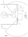
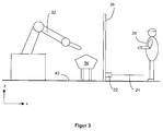
- Such a system 20 is in Fig. 2 and 3 shown. It may be, for example, a mounting robot, welding robot, press brake or the like machine.
- the plant model is designed so that the working movements of the plant 20 can be simulated three-dimensionally in the computer.
- a 3-D computer model of a safety sensor 22 is stored in the memory, the sensor model comprising a detection area 26 of the sensor 22 comprising a protective field 24 and a warning field 25 of the sensor 22.
- a 3-D computer model of a safety-critical object 28 is deposited, which is shown here as a person 28.
- the object model 28 can be moved via input means, for example the mouse 18 or the keyboard 16, in the virtual space (arrow 30).
- the installation 20 comprises a robot 32, a workpiece 34 to be machined by the robot, and a protective fence 36.
- the method is used for safety planning, configuration and analysis of the industrial plant 20.
- the 3-D plant model comprises the robot 32, the workpiece to be machined by the robot 34 and the protective fence 36.
- the illustrated simulation which is usually on the screen 14 is shown, all working movements of the system 20 are three-dimensional simulated.
- the sensor 22 is positioned and aligned to a suitable position in space. In this example, at the edge of the passage 38 just above the bottom 40. Then, corresponding protective fields 24 and 25 within the detection range 26 of the Sensors 22 defined, dimensioned and aligned, which could be done for example by pulling the mouse 18. Furthermore, in a communication option, not shown, for example, via the keyboard 16, the security information must be entered into the system 10, which could consist in determining how the system should react when the protective field 24 and the warning field 25 are violated. One possible configuration would be, for example, that if the warning field 25 is violated, only a slowdown of the robot 32 takes place and if the protective field 24 is breached an emergency stop of the robot 32 occurs.
- a possible safety test can be to move the object model 28 into the warning field 25 or into the protective field 24, so that warning and protective field are violated and then the reactions of the sensor model 22 and the plant model 20, calculated in the computer and on the Screen to be viewed, observed and judged. If the reactions are safety-related, e.g. the robot 32 does not perform an emergency stop in the event of a protective field violation, then the configuration is classified as inadmissible and must be re-made with changed configuration parameters. Of course, the configuration parameters must be changeable.
- a typical example of such a test would be, for example, the correct switching of protective fields 24. If, for example, the sensor 22 is to activate various protective fields 24, each with different dimensions, depending on the position of the robot 32 Passage 38, a small protective field 24 may be activated, whereas a larger protective field 24 should be active when the robot is close to the passage. Configuration parameters that define the protective field size would have to be be dynamically changeable during a working movement of the robot 32. The correct configuration can then be checked graphically on the screen 14 with the method and system according to the invention in the simplest manner.
- the configuration parameters for the sensor 22, which correspond to a safety-related standard-conforming configuration found using the method and system according to the invention, can then be transferred from the simulation to the real sensor and do not have to be entered again separately into the sensor.
Claims (10)
- Système pour la planification de la sécurité, la configuration et l'analyse d'une installation industrielle (20) avec un potentiel de risque, avec un ordinateur (12), dans lequel l'installation est stockée dans une mémoire de l'ordinateur sous la forme d'un modèle informatique 3-D, dans lequel le modèle de l'installation permet de simuler en trois dimensions les déplacements de travail de l'installation (20), et un modèle informatique 3D d'un capteur de sécurité (22) ainsi qu'un modèle informatique 3D d'un objet critique pour la sécurité (28) sont stockés dans la mémoire, caractérisé en ce que le modèle de capteur comprend une zone de détection (26) du capteur qui comprend des champs de protection sous forme graphique visualisable (24, 25) qui peuvent être adaptés et commutés dans leurs dimensions ou orientations au moyen de paramètres de configuration, dans lequel l'objet modèle peut être déplacé dans l'espace virtuel par l'intermédiaire des moyens d'entrées (16, 18) et peut être amené dans une zone protégée (24, 25) du modèle de capteur (22), et à cette violation du champ de protection (24, 25) une réaction du modèle de capteur (22) et le modèle de l'installation (20) est affichable.
- Système selon la revendication 1, caractérisé en ce que les paramètres de configuration correspondent à ceux du capteur réel et sont modifiables.
- Système selon l'une des revendications précédentes, caractérisé en ce que les paramètres de configuration sont modifiables dynamiquement au cours d'un mouvement de travail du modèle d'installation.
- Système selon l'une des revendications précédentes, caractérisé en ce que le modèle de capteur comprend des paramètres d'erreur par lesquels des erreurs liés à la sécurité peuvent être simulés et une réponse du modèle de capteur et du modèle de l'installation aux erreurs est affiché.
- Système selon l'une des revendications précédentes, caractérisé en ce que les propriétés du modèle de capteur et du modèle d'objet simulent les exigences des normes de sécurité.
- Système selon l'une des revendications précédentes, caractérisé en ce que le modèle de capteur est disponible en tant que module de programme.
- Procédé pour la planification de la sécurité, la configuration et l'analyse d'une installation industrielle avec un potentiel de risque avec un système selon l'une des revendications précédentes, dans lequel un ordinateur affiche un modèle informatique 3D du système, le modèle peut simuler en trois dimensions les déplacements de travail de l'installation, un modèle informatique 3D d'un capteur de sécurité est affiché et un modèle informatique 3D d'un objet critique pour la sécurité est affiché et une réaction du modèle d'installation est calculée et affichée par l'ordinateur lors de la simulation les défaillances de sécurité au modèle de capteur, caractérisé en ce que les zones de protection du capteur qui sont dimensionnables, réglables et commutables sont affichés sous forme graphique au moyen de paramètres de configuration, et que l'objet peut être déplacé dans l'espace virtuel et peut être amené dans une zone protégée du modèle de capteur, et à cette violation du champ de protection une réaction du modèle de capteur (22) est affichable.
- Procédé selon la revendication 7, caractérisé en ce que des paramètres de configuration appropriés pour le modèle de capteur se trouvent avec la simulation et qui sont transmis au capteur réel après la simulation.
- Programme informatique comportant des moyens de code de programme pour réaliser un procédé selon la revendication 7 ou 8.
- Produit de programme informatique comprenant un support de stockage sur lequel un programme informatique est stocké selon la revendication 9.
Priority Applications (1)
| Application Number | Priority Date | Filing Date | Title |
|---|---|---|---|
| EP10159937.1A EP2378445B1 (fr) | 2010-04-14 | 2010-04-14 | Système et procédé de planification de sécurité d'une installation industrielle présentant un potentiel de risque |
Applications Claiming Priority (1)
| Application Number | Priority Date | Filing Date | Title |
|---|---|---|---|
| EP10159937.1A EP2378445B1 (fr) | 2010-04-14 | 2010-04-14 | Système et procédé de planification de sécurité d'une installation industrielle présentant un potentiel de risque |
Publications (2)
| Publication Number | Publication Date |
|---|---|
| EP2378445A1 EP2378445A1 (fr) | 2011-10-19 |
| EP2378445B1 true EP2378445B1 (fr) | 2016-05-11 |
Family
ID=42594727
Family Applications (1)
| Application Number | Title | Priority Date | Filing Date |
|---|---|---|---|
| EP10159937.1A Active EP2378445B1 (fr) | 2010-04-14 | 2010-04-14 | Système et procédé de planification de sécurité d'une installation industrielle présentant un potentiel de risque |
Country Status (1)
| Country | Link |
|---|---|
| EP (1) | EP2378445B1 (fr) |
Cited By (2)
| Publication number | Priority date | Publication date | Assignee | Title |
|---|---|---|---|---|
| DE202020106491U1 (de) | 2020-11-12 | 2022-02-16 | Sick Ag | Visualisieren eines Schutzfeldes |
| DE102020129823A1 (de) | 2020-11-12 | 2022-05-12 | Sick Ag | Visualisieren eines Schutzfeldes |
Families Citing this family (8)
| Publication number | Priority date | Publication date | Assignee | Title |
|---|---|---|---|---|
| US9430589B2 (en) | 2013-02-05 | 2016-08-30 | Rockwell Automation Technologies, Inc. | Safety automation builder |
| CN103279599B (zh) * | 2013-05-15 | 2015-10-07 | 西北工业大学 | 一种基于交互特征偶的产品建模方法 |
| DE102015220493A1 (de) * | 2015-10-21 | 2017-04-27 | Kuka Roboter Gmbh | Verifikation einer Position eines Manipulatorsystems |
| DE102015220495A1 (de) | 2015-10-21 | 2017-04-27 | Kuka Roboter Gmbh | Schutzfeldanpassung eines Manipulatorsystems |
| US11493908B2 (en) | 2018-11-13 | 2022-11-08 | Rockwell Automation Technologies, Inc. | Industrial safety monitoring configuration using a digital twin |
| CN113927213A (zh) * | 2020-07-13 | 2022-01-14 | 一汽-大众汽车有限公司 | 用于提供三维安全组合模块的方法和装置 |
| EP4173766A1 (fr) | 2021-10-28 | 2023-05-03 | Sick Ag | Dispositif et procédé pour la programmation et/ou l'opération d'une machine mobile, en particulier d'un robot |
| DE202021105907U1 (de) | 2021-10-28 | 2023-01-31 | Sick Ag | Vorrichtung zum Programmieren und/oder Betreiben einer beweglichen Maschine, insbesondere eines Roboters |
Family Cites Families (2)
| Publication number | Priority date | Publication date | Assignee | Title |
|---|---|---|---|---|
| US7237109B2 (en) * | 2003-01-28 | 2007-06-26 | Fisher- Rosemount Systems, Inc. | Integrated security in a process plant having a process control system and a safety system |
| EP1785745A1 (fr) * | 2005-11-10 | 2007-05-16 | Omron Electronics Manufacturing of Germany GmbH | Procédé et unité de commande destinés à la configuration et à la surveillance d un dispositif muni d une sécurité fonctionnelle |
-
2010
- 2010-04-14 EP EP10159937.1A patent/EP2378445B1/fr active Active
Non-Patent Citations (1)
| Title |
|---|
| None * |
Cited By (4)
| Publication number | Priority date | Publication date | Assignee | Title |
|---|---|---|---|---|
| DE202020106491U1 (de) | 2020-11-12 | 2022-02-16 | Sick Ag | Visualisieren eines Schutzfeldes |
| DE102020129823A1 (de) | 2020-11-12 | 2022-05-12 | Sick Ag | Visualisieren eines Schutzfeldes |
| EP4000815A1 (fr) | 2020-11-12 | 2022-05-25 | Sick Ag | Visualisation d'un champ de protection |
| DE102020129823B4 (de) | 2020-11-12 | 2022-07-07 | Sick Ag | Visualisieren eines Schutzfeldes |
Also Published As
| Publication number | Publication date |
|---|---|
| EP2378445A1 (fr) | 2011-10-19 |
Similar Documents
| Publication | Publication Date | Title |
|---|---|---|
| EP2378445B1 (fr) | Système et procédé de planification de sécurité d'une installation industrielle présentant un potentiel de risque | |
| EP1906281B1 (fr) | Procédé et système pour la conception et la vérification de zones de sécurité d'un robot industriel | |
| EP2353052B1 (fr) | Commande de sécurité et procédé de commande d une installation automatisée | |
| EP2023160B1 (fr) | Surveillance spatiale tridimensionnelle dotée d'un mode de configuration pour la détermination des champs de protection | |
| CN104143040A (zh) | 移动自动化环境中的人员安全措施 | |
| EP3324362A1 (fr) | Procédé et dispositif de mise en service d'un système multiaxes | |
| EP3189947A1 (fr) | Procede de configuration et de fonctionnement d'une cellule de travail automatisee surveillee et dispositif de configuration | |
| EP2098925A1 (fr) | Procédé et dispositif adaptés à la programmation et/ou la configuration d'un contrôleur de sécurité | |
| EP2053538A1 (fr) | Protection d'une zone de surveillance et support visuel d'un usinage automatisé | |
| DE102013000250A1 (de) | Konfigurierbare Sicherheitsüberwachung für eine Roboteranordnung | |
| EP2977148A1 (fr) | Procede et dispositif destines a la commande d'un robot | |
| EP3323565B1 (fr) | Procédé et dispositif de mise en service d'un système multiaxial | |
| WO2019025248A1 (fr) | Procédé et système de vérification et/ou modification d'un processus de travail d'un robot | |
| EP2625008B1 (fr) | Commande de robot | |
| EP2835699B1 (fr) | Dispositif et procédé de configuration et/ou de programmation d'un contrôleur de sécurité | |
| DE102004020994B4 (de) | Verfahren und Vorrichtung zum computergestützten Konstruieren einer sicherheitsgerichteten elektrischen Schaltung | |
| DE102015219369A1 (de) | Sicherheitseinrichtung für eine Strahlbearbeitungsvorrichtung und Verfahren | |
| EP4124789A1 (fr) | Fixation d'une pièce de machine mobile | |
| EP3588271A1 (fr) | Procédé et dispositif de configuration d'un composant matériel | |
| DE102020129823B4 (de) | Visualisieren eines Schutzfeldes | |
| EP3427904B1 (fr) | Système comprenant un manipulateur et un dispositif de limitation d'un espace de travail | |
| EP4173766A1 (fr) | Dispositif et procédé pour la programmation et/ou l'opération d'une machine mobile, en particulier d'un robot | |
| DE102018113361B4 (de) | Sensorsystem mit optoelektronischen Distanzsensoren | |
| DE102009027269A1 (de) | System und Verfahren zur Überwachung des Zustands einer Maschine | |
| DE102021208279B4 (de) | Integration einer Risikobeurteilung einer Kollision zwischen einem robotischen Gerät und einer menschlichen Bedienperson |
Legal Events
| Date | Code | Title | Description |
|---|---|---|---|
| AK | Designated contracting states |
Kind code of ref document: A1 Designated state(s): AT BE BG CH CY CZ DE DK EE ES FI FR GB GR HR HU IE IS IT LI LT LU LV MC MK MT NL NO PL PT RO SE SI SK SM TR |
|
| AX | Request for extension of the european patent |
Extension state: AL BA ME RS |
|
| PUAI | Public reference made under article 153(3) epc to a published international application that has entered the european phase |
Free format text: ORIGINAL CODE: 0009012 |
|
| 17P | Request for examination filed |
Effective date: 20120301 |
|
| 17Q | First examination report despatched |
Effective date: 20120827 |
|
| RIC1 | Information provided on ipc code assigned before grant |
Ipc: G05B 19/042 20060101ALN20151201BHEP Ipc: G06F 17/50 20060101AFI20151201BHEP |
|
| RIC1 | Information provided on ipc code assigned before grant |
Ipc: G06F 17/50 20060101AFI20151204BHEP Ipc: G05B 19/042 20060101ALN20151204BHEP |
|
| GRAP | Despatch of communication of intention to grant a patent |
Free format text: ORIGINAL CODE: EPIDOSNIGR1 |
|
| GRAS | Grant fee paid |
Free format text: ORIGINAL CODE: EPIDOSNIGR3 |
|
| RIC1 | Information provided on ipc code assigned before grant |
Ipc: G06F 17/50 20060101AFI20160224BHEP Ipc: G05B 19/042 20060101ALN20160224BHEP |
|
| INTG | Intention to grant announced |
Effective date: 20160309 |
|
| GRAA | (expected) grant |
Free format text: ORIGINAL CODE: 0009210 |
|
| AK | Designated contracting states |
Kind code of ref document: B1 Designated state(s): AT BE BG CH CY CZ DE DK EE ES FI FR GB GR HR HU IE IS IT LI LT LU LV MC MK MT NL NO PL PT RO SE SI SK SM TR |
|
| REG | Reference to a national code |
Ref country code: GB Ref legal event code: FG4D Free format text: NOT ENGLISH |
|
| REG | Reference to a national code |
Ref country code: CH Ref legal event code: EP |
|
| REG | Reference to a national code |
Ref country code: AT Ref legal event code: REF Ref document number: 799158 Country of ref document: AT Kind code of ref document: T Effective date: 20160515 |
|
| REG | Reference to a national code |
Ref country code: IE Ref legal event code: FG4D Free format text: LANGUAGE OF EP DOCUMENT: GERMAN |
|
| REG | Reference to a national code |
Ref country code: DE Ref legal event code: R096 Ref document number: 502010011637 Country of ref document: DE |
|
| REG | Reference to a national code |
Ref country code: LT Ref legal event code: MG4D |
|
| REG | Reference to a national code |
Ref country code: NL Ref legal event code: MP Effective date: 20160511 |
|
| PG25 | Lapsed in a contracting state [announced via postgrant information from national office to epo] |
Ref country code: FI Free format text: LAPSE BECAUSE OF FAILURE TO SUBMIT A TRANSLATION OF THE DESCRIPTION OR TO PAY THE FEE WITHIN THE PRESCRIBED TIME-LIMIT Effective date: 20160511 Ref country code: NL Free format text: LAPSE BECAUSE OF FAILURE TO SUBMIT A TRANSLATION OF THE DESCRIPTION OR TO PAY THE FEE WITHIN THE PRESCRIBED TIME-LIMIT Effective date: 20160511 Ref country code: NO Free format text: LAPSE BECAUSE OF FAILURE TO SUBMIT A TRANSLATION OF THE DESCRIPTION OR TO PAY THE FEE WITHIN THE PRESCRIBED TIME-LIMIT Effective date: 20160811 Ref country code: LT Free format text: LAPSE BECAUSE OF FAILURE TO SUBMIT A TRANSLATION OF THE DESCRIPTION OR TO PAY THE FEE WITHIN THE PRESCRIBED TIME-LIMIT Effective date: 20160511 |
|
| PG25 | Lapsed in a contracting state [announced via postgrant information from national office to epo] |
Ref country code: LV Free format text: LAPSE BECAUSE OF FAILURE TO SUBMIT A TRANSLATION OF THE DESCRIPTION OR TO PAY THE FEE WITHIN THE PRESCRIBED TIME-LIMIT Effective date: 20160511 Ref country code: GR Free format text: LAPSE BECAUSE OF FAILURE TO SUBMIT A TRANSLATION OF THE DESCRIPTION OR TO PAY THE FEE WITHIN THE PRESCRIBED TIME-LIMIT Effective date: 20160812 Ref country code: PT Free format text: LAPSE BECAUSE OF FAILURE TO SUBMIT A TRANSLATION OF THE DESCRIPTION OR TO PAY THE FEE WITHIN THE PRESCRIBED TIME-LIMIT Effective date: 20160912 Ref country code: HR Free format text: LAPSE BECAUSE OF FAILURE TO SUBMIT A TRANSLATION OF THE DESCRIPTION OR TO PAY THE FEE WITHIN THE PRESCRIBED TIME-LIMIT Effective date: 20160511 Ref country code: ES Free format text: LAPSE BECAUSE OF FAILURE TO SUBMIT A TRANSLATION OF THE DESCRIPTION OR TO PAY THE FEE WITHIN THE PRESCRIBED TIME-LIMIT Effective date: 20160511 Ref country code: SE Free format text: LAPSE BECAUSE OF FAILURE TO SUBMIT A TRANSLATION OF THE DESCRIPTION OR TO PAY THE FEE WITHIN THE PRESCRIBED TIME-LIMIT Effective date: 20160511 |
|
| PG25 | Lapsed in a contracting state [announced via postgrant information from national office to epo] |
Ref country code: IT Free format text: LAPSE BECAUSE OF FAILURE TO SUBMIT A TRANSLATION OF THE DESCRIPTION OR TO PAY THE FEE WITHIN THE PRESCRIBED TIME-LIMIT Effective date: 20160511 |
|
| PG25 | Lapsed in a contracting state [announced via postgrant information from national office to epo] |
Ref country code: EE Free format text: LAPSE BECAUSE OF FAILURE TO SUBMIT A TRANSLATION OF THE DESCRIPTION OR TO PAY THE FEE WITHIN THE PRESCRIBED TIME-LIMIT Effective date: 20160511 Ref country code: DK Free format text: LAPSE BECAUSE OF FAILURE TO SUBMIT A TRANSLATION OF THE DESCRIPTION OR TO PAY THE FEE WITHIN THE PRESCRIBED TIME-LIMIT Effective date: 20160511 Ref country code: CZ Free format text: LAPSE BECAUSE OF FAILURE TO SUBMIT A TRANSLATION OF THE DESCRIPTION OR TO PAY THE FEE WITHIN THE PRESCRIBED TIME-LIMIT Effective date: 20160511 Ref country code: SK Free format text: LAPSE BECAUSE OF FAILURE TO SUBMIT A TRANSLATION OF THE DESCRIPTION OR TO PAY THE FEE WITHIN THE PRESCRIBED TIME-LIMIT Effective date: 20160511 Ref country code: RO Free format text: LAPSE BECAUSE OF FAILURE TO SUBMIT A TRANSLATION OF THE DESCRIPTION OR TO PAY THE FEE WITHIN THE PRESCRIBED TIME-LIMIT Effective date: 20160511 |
|
| REG | Reference to a national code |
Ref country code: DE Ref legal event code: R097 Ref document number: 502010011637 Country of ref document: DE |
|
| PG25 | Lapsed in a contracting state [announced via postgrant information from national office to epo] |
Ref country code: SM Free format text: LAPSE BECAUSE OF FAILURE TO SUBMIT A TRANSLATION OF THE DESCRIPTION OR TO PAY THE FEE WITHIN THE PRESCRIBED TIME-LIMIT Effective date: 20160511 Ref country code: PL Free format text: LAPSE BECAUSE OF FAILURE TO SUBMIT A TRANSLATION OF THE DESCRIPTION OR TO PAY THE FEE WITHIN THE PRESCRIBED TIME-LIMIT Effective date: 20160511 |
|
| PLBE | No opposition filed within time limit |
Free format text: ORIGINAL CODE: 0009261 |
|
| STAA | Information on the status of an ep patent application or granted ep patent |
Free format text: STATUS: NO OPPOSITION FILED WITHIN TIME LIMIT |
|
| 26N | No opposition filed |
Effective date: 20170214 |
|
| REG | Reference to a national code |
Ref country code: FR Ref legal event code: PLFP Year of fee payment: 8 |
|
| PG25 | Lapsed in a contracting state [announced via postgrant information from national office to epo] |
Ref country code: SI Free format text: LAPSE BECAUSE OF FAILURE TO SUBMIT A TRANSLATION OF THE DESCRIPTION OR TO PAY THE FEE WITHIN THE PRESCRIBED TIME-LIMIT Effective date: 20160511 |
|
| PG25 | Lapsed in a contracting state [announced via postgrant information from national office to epo] |
Ref country code: MC Free format text: LAPSE BECAUSE OF FAILURE TO SUBMIT A TRANSLATION OF THE DESCRIPTION OR TO PAY THE FEE WITHIN THE PRESCRIBED TIME-LIMIT Effective date: 20160511 |
|
| REG | Reference to a national code |
Ref country code: IE Ref legal event code: MM4A |
|
| PG25 | Lapsed in a contracting state [announced via postgrant information from national office to epo] |
Ref country code: LU Free format text: LAPSE BECAUSE OF NON-PAYMENT OF DUE FEES Effective date: 20170414 |
|
| REG | Reference to a national code |
Ref country code: BE Ref legal event code: MM Effective date: 20170430 |
|
| REG | Reference to a national code |
Ref country code: FR Ref legal event code: PLFP Year of fee payment: 9 |
|
| PG25 | Lapsed in a contracting state [announced via postgrant information from national office to epo] |
Ref country code: IE Free format text: LAPSE BECAUSE OF NON-PAYMENT OF DUE FEES Effective date: 20170414 |
|
| PG25 | Lapsed in a contracting state [announced via postgrant information from national office to epo] |
Ref country code: BE Free format text: LAPSE BECAUSE OF NON-PAYMENT OF DUE FEES Effective date: 20170430 |
|
| REG | Reference to a national code |
Ref country code: AT Ref legal event code: MM01 Ref document number: 799158 Country of ref document: AT Kind code of ref document: T Effective date: 20170414 |
|
| PG25 | Lapsed in a contracting state [announced via postgrant information from national office to epo] |
Ref country code: AT Free format text: LAPSE BECAUSE OF NON-PAYMENT OF DUE FEES Effective date: 20170414 |
|
| PG25 | Lapsed in a contracting state [announced via postgrant information from national office to epo] |
Ref country code: MT Free format text: LAPSE BECAUSE OF FAILURE TO SUBMIT A TRANSLATION OF THE DESCRIPTION OR TO PAY THE FEE WITHIN THE PRESCRIBED TIME-LIMIT Effective date: 20160511 |
|
| PG25 | Lapsed in a contracting state [announced via postgrant information from national office to epo] |
Ref country code: HU Free format text: LAPSE BECAUSE OF FAILURE TO SUBMIT A TRANSLATION OF THE DESCRIPTION OR TO PAY THE FEE WITHIN THE PRESCRIBED TIME-LIMIT; INVALID AB INITIO Effective date: 20100414 |
|
| PG25 | Lapsed in a contracting state [announced via postgrant information from national office to epo] |
Ref country code: BG Free format text: LAPSE BECAUSE OF FAILURE TO SUBMIT A TRANSLATION OF THE DESCRIPTION OR TO PAY THE FEE WITHIN THE PRESCRIBED TIME-LIMIT Effective date: 20160511 |
|
| PG25 | Lapsed in a contracting state [announced via postgrant information from national office to epo] |
Ref country code: CY Free format text: LAPSE BECAUSE OF NON-PAYMENT OF DUE FEES Effective date: 20160511 |
|
| REG | Reference to a national code |
Ref country code: DE Ref legal event code: R079 Ref document number: 502010011637 Country of ref document: DE Free format text: PREVIOUS MAIN CLASS: G06F0017500000 Ipc: G06F0030000000 |
|
| PG25 | Lapsed in a contracting state [announced via postgrant information from national office to epo] |
Ref country code: MK Free format text: LAPSE BECAUSE OF FAILURE TO SUBMIT A TRANSLATION OF THE DESCRIPTION OR TO PAY THE FEE WITHIN THE PRESCRIBED TIME-LIMIT Effective date: 20160511 |
|
| PG25 | Lapsed in a contracting state [announced via postgrant information from national office to epo] |
Ref country code: TR Free format text: LAPSE BECAUSE OF FAILURE TO SUBMIT A TRANSLATION OF THE DESCRIPTION OR TO PAY THE FEE WITHIN THE PRESCRIBED TIME-LIMIT Effective date: 20160511 |
|
| PG25 | Lapsed in a contracting state [announced via postgrant information from national office to epo] |
Ref country code: IS Free format text: LAPSE BECAUSE OF FAILURE TO SUBMIT A TRANSLATION OF THE DESCRIPTION OR TO PAY THE FEE WITHIN THE PRESCRIBED TIME-LIMIT Effective date: 20160911 |
|
| PGFP | Annual fee paid to national office [announced via postgrant information from national office to epo] |
Ref country code: CH Payment date: 20210422 Year of fee payment: 12 |
|
| PGFP | Annual fee paid to national office [announced via postgrant information from national office to epo] |
Ref country code: GB Payment date: 20220425 Year of fee payment: 13 Ref country code: FR Payment date: 20220420 Year of fee payment: 13 |
|
| REG | Reference to a national code |
Ref country code: CH Ref legal event code: PL |
|
| PG25 | Lapsed in a contracting state [announced via postgrant information from national office to epo] |
Ref country code: LI Free format text: LAPSE BECAUSE OF NON-PAYMENT OF DUE FEES Effective date: 20220430 Ref country code: CH Free format text: LAPSE BECAUSE OF NON-PAYMENT OF DUE FEES Effective date: 20220430 |
|
| PGFP | Annual fee paid to national office [announced via postgrant information from national office to epo] |
Ref country code: DE Payment date: 20230418 Year of fee payment: 14 |
|
| GBPC | Gb: european patent ceased through non-payment of renewal fee |
Effective date: 20230414 |
|
| PG25 | Lapsed in a contracting state [announced via postgrant information from national office to epo] |
Ref country code: GB Free format text: LAPSE BECAUSE OF NON-PAYMENT OF DUE FEES Effective date: 20230414 |
|
| PG25 | Lapsed in a contracting state [announced via postgrant information from national office to epo] |
Ref country code: GB Free format text: LAPSE BECAUSE OF NON-PAYMENT OF DUE FEES Effective date: 20230414 Ref country code: FR Free format text: LAPSE BECAUSE OF NON-PAYMENT OF DUE FEES Effective date: 20230430 |