EP2378207A1 - Cooking arrangement - Google Patents
Cooking arrangement Download PDFInfo
- Publication number
- EP2378207A1 EP2378207A1 EP20100003525 EP10003525A EP2378207A1 EP 2378207 A1 EP2378207 A1 EP 2378207A1 EP 20100003525 EP20100003525 EP 20100003525 EP 10003525 A EP10003525 A EP 10003525A EP 2378207 A1 EP2378207 A1 EP 2378207A1
- Authority
- EP
- European Patent Office
- Prior art keywords
- carrier frame
- cooking
- worktop
- arrangement according
- cooking hob
- Prior art date
- Legal status (The legal status is an assumption and is not a legal conclusion. Google has not performed a legal analysis and makes no representation as to the accuracy of the status listed.)
- Granted
Links
- 238000010411 cooking Methods 0.000 title claims abstract description 99
- 238000007789 sealing Methods 0.000 claims description 11
- 239000000853 adhesive Substances 0.000 claims description 4
- 230000001070 adhesive effect Effects 0.000 claims description 4
- 229910000831 Steel Inorganic materials 0.000 claims description 3
- 239000004411 aluminium Substances 0.000 claims description 3
- 229910052782 aluminium Inorganic materials 0.000 claims description 3
- XAGFODPZIPBFFR-UHFFFAOYSA-N aluminium Chemical compound [Al] XAGFODPZIPBFFR-UHFFFAOYSA-N 0.000 claims description 3
- 238000005266 casting Methods 0.000 claims description 3
- 238000005286 illumination Methods 0.000 claims description 3
- 239000010959 steel Substances 0.000 claims description 3
- 239000002023 wood Substances 0.000 claims description 3
- 238000010297 mechanical methods and process Methods 0.000 claims description 2
- 230000005226 mechanical processes and functions Effects 0.000 claims description 2
- 238000003754 machining Methods 0.000 abstract description 3
- 229910052751 metal Inorganic materials 0.000 description 4
- 239000002184 metal Substances 0.000 description 4
- 239000000463 material Substances 0.000 description 3
- 239000000919 ceramic Substances 0.000 description 1
- 230000000694 effects Effects 0.000 description 1
- 238000004880 explosion Methods 0.000 description 1
- 239000011521 glass Substances 0.000 description 1
- 239000002241 glass-ceramic Substances 0.000 description 1
- 239000003973 paint Substances 0.000 description 1
- 230000000284 resting effect Effects 0.000 description 1
- 239000007787 solid Substances 0.000 description 1
- 239000011343 solid material Substances 0.000 description 1
- 229910001220 stainless steel Inorganic materials 0.000 description 1
- 239000010935 stainless steel Substances 0.000 description 1
Images




Classifications
-
- F—MECHANICAL ENGINEERING; LIGHTING; HEATING; WEAPONS; BLASTING
- F24—HEATING; RANGES; VENTILATING
- F24C—DOMESTIC STOVES OR RANGES ; DETAILS OF DOMESTIC STOVES OR RANGES, OF GENERAL APPLICATION
- F24C15/00—Details
- F24C15/10—Tops, e.g. hot plates; Rings
- F24C15/108—Mounting of hot plate on worktop
Definitions
- the invention relates to a cooking arrangement comprising a cooking hob which is arranged on a worktop, wherein the cooking hob is supported on the worktop by means of a carrier frame, wherein the cooking hob has a vertical height and a bottom side with a bottom surface which is directed vertically downwards and wherein the worktop has a top surface which is directed vertically upwards.
- the worktop is serving as the containing element for the cooking hob.
- a respective cutout must be machined. Due to the size of the cooking hob, which can vary in a wide range, it is not possible to define any standard dimension for the cutout in the worktop. If another (new) cooking hob has to be mounted into an existing worktop it is thus necessary to re-machine the cutout to adapt it to the new required size. If in fact the new cooking hob requires only a smaller cutout it is normally necessary to purchase a new worktop so that the cooking hob reasonable fits into the worktop. This makes the mounting of a (new) cooking hob expensive.
- the cooking hob has a certain vertical height, so that the bottom part of the cooking hob extends more of less far below the working top. This makes it sometimes problematic to arrange devices (like refrigerators or dish washers) or drawers below the cooking hob. So, sometimes space in the kitchen cannot be used most efficiently.
- the solution of this object is characterized in that the carrier frame is designed to support the cooking hob in such a way that the bottom surface of the cooking hob is positioned in a vertical height equal or above the vertical height of the top surface of the worktop.
- the carrier frame has a first bearing area for being arranged on the top surface of the worktop and has a second bearing surface for the cooking hob being arranged on it.
- the carrier frame can have a substantial rectangular form. It can consist of four rails, wherein two rails are connected to another. The connection of two rails can be established and/or reinforced by means of a corner connection.
- the carrier frame can consist of parts machined from a profiled element.
- the profiled element can have at least on hollow section.
- the profiled element can be made by a casting process or by a mechanical process.
- the carrier frame can further comprise a base body which is covered at its outer side by a panel.
- the panel can be affixed to the base body by means of a snap connection. Also, it is possible that the panel is affixed to the base body by means of an adhesive.
- the carrier frame and/or its parts are preferably made of wood, steel and/or aluminium.
- a switch element, an illumination element and/or a display element is integrated into the carrier frame.
- Connection means can be arranged between the cooking hob and the carrier frame, wherein the carrier frame has preferably a form fit connection element for engagement of the connection means.
- the proposed carrier frame it is possible to lift the cooking hob in such a way that the space below the cooking hob remains sufficient to arrange a drawer or a kitchen device (e. g. a dish washer or a refrigerator) without space problems.
- the lifting is done in such a way that the bottom part of the cooking hob does not extend downwards below the worktop.
- the carrier frame By the simple design of the carrier frame, especially when profiled material is used for the frame, it is possible without any problems to arrange a cooking hob on a worktop in a very flexible and cost-efficient manner.
- the frame can be produced in the desired size very easy to fit to the size of the cooking hob. So, if a cutout is already existing in the worktop which has to be covered by a (new) cooking hob it is possible to select the carrier frame to cover different cutout sizes and to carry cooking hobs of different sizes.
- the carrier frame Due to the simple design of the carrier frame it is also possible to produce the frame in different heights.
- the height can be varied in such a manner that according to the desired device below the cooking hob (drawer, refrigerator, dish washer) the required space exists for the device. It is of course also possible to lift the cooking hob by the carrier frame just to that extend that no cutout is required to mount the cooking hob onto the worktop. So, the cooking hob becomes quite mobile and can be used at different locations.
- the carrier frame can consist of a base body which can be made from a solid material (made by casting or mechanical machining) or can have a hollow section. Extruded metal profiles (solid or hollow ones) can also be employed.
- the base body can consist of wood, steel aluminium or similar material. It is also possible to paint the base body or to attach special design part at it. Those design parts can also consist of different materials like glass, metal (also painted metal), stainless steel or the like.
- carrier frame storage surfaces e. g. for cookware. Those surfaces can also be integrated into the design of the carrier frame. Those storage surfaces can be permanently fixed with the carrier frame or can be designed as detachable parts.
- the carrier frame can be printed, e. g. with a company logo or with symbols.
- the carrier frame can also be equipped with an outlet for a cable or with reception elements for mounting springs of the cooking hob.
- the carrier frame can be simply arranged without any fixation onto the worktop or another support.
- the carrier frame can also be affixed with a worktop by means of screws or adhesives or the like.
- a special fixation strip can be used for affixing the carrier frame to the worktop.
- a sealing strip can be arranged in the region of the contact surfaces between the carrier frame and the worktop as well as between the carrier frame and the cooking hob.
- a groove can be machined into the carrier frame or its parts.
- FIG 1 a cooking arrangement 1 is shown which consists of a cooking hob 2 (with a ceramic stove top) which is affixed on a worktop 3 of a kitchen.
- a carrier frame 4 is employed for the fixation of the cooking hob 2 on the worktop 3 .
- the carrier frame 4 carries the cooking hob 2 and is itself arranged on the top surface 7 of the worktop 3.
- the cooking hob 2 has a certain vertical height H, measured from the top surface of the cooking hob 2 to a bottom surface 6 of a bottom side 5 of the cooking hob 2.
- the bottom side 5 is made of sheet metal and protects the cooking hob 2 in its lower region.
- the worktop has a top surface 7 which is arranged in a certain vertical height (vertical direction V).
- the worktop 3 has already a cutout 20 which was used for the reception of a former cooking hob which had to be substituted by the depicted cooking hob 3.
- the cooking hob 3 is carried by a carrier frame 4 which has a first bearing area 8 which is resting on the top surface 7 of the worktop 3. Furthermore, the carrier frame 4 has a second bearing surface 9 on which the cooking hob 2 rests with a lateral extending part (which is a glass ceramic stove top in the present case).
- the carrier frame 4 consists of rails 10 (see FIG 3 ) having a base body 14, which is made from a profiled element 12 with a hollow section 13.
- the base body 14 is covered by a panel 15.
- the panel 15 can be affixed to the base body 14 by means of an adhesive.
- the size of the base body 14 is selected in such a way that the bottom surface 6 of the cooking hob 3 is in the same height or higher than the top surface 7 of the worktop 3. In the case depicted in FIG 2 there is even a certain distance x, so that the bottom surface 6 is in fact a little higher than the top surface 7. This means, that a cutout 20 in the worktop is not necessary to mount the cooking hob 2 on the worktop 3.
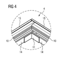
- the carrier frame 4 is put together from four rails 10 which are connected in the corners of the frame by means of corner connections 11 as can be seen in detail in FIG 4 .
- each base body 14 of the carrier frame is covered by a panel 15 to get a proper outer appearance.
- the base body 14 can be equipped with a groove 18 in which a sealing element 19 (sealing strip) is arranged. So a proper sealing effect is obtained between the worktop 3 and the carrier frame 4 (and also - what is not depicted - between the carrier frame 4 and the cooking hob 2).
- a sealing element 19 sealing strip
Landscapes
- Engineering & Computer Science (AREA)
- Chemical & Material Sciences (AREA)
- Combustion & Propulsion (AREA)
- Mechanical Engineering (AREA)
- General Engineering & Computer Science (AREA)
- Induction Heating Cooking Devices (AREA)
- Baking, Grill, Roasting (AREA)
- Combinations Of Kitchen Furniture (AREA)
Abstract
Description
- The invention relates to a cooking arrangement comprising a cooking hob which is arranged on a worktop, wherein the cooking hob is supported on the worktop by means of a carrier frame, wherein the cooking hob has a vertical height and a bottom side with a bottom surface which is directed vertically downwards and wherein the worktop has a top surface which is directed vertically upwards.
- Cooking arrangements of this kind are well-known in the art.
DE 21 66 827 C3 shows such a solution. A cutout is machined into a worktop of a kitchen. The size of the cutout corresponds to the size of the bottom part of the cooking hob which has to be mounted into the cutout of the worktop. A frame element is used which holds the cooking hob and is itself connected to the worktop at the edge of the cutout. Consequently, the size of the cutout must be machined according to the size of the cooking hob which has to be mounted into the worktop. - Similar solutions are known from
EP 2 110 608 A1DE 20 2006 000 248 U1 - Thus, the worktop is serving as the containing element for the cooking hob. For arranging of the cooking hub in the worktop a respective cutout must be machined. Due to the size of the cooking hob, which can vary in a wide range, it is not possible to define any standard dimension for the cutout in the worktop. If another (new) cooking hob has to be mounted into an existing worktop it is thus necessary to re-machine the cutout to adapt it to the new required size. If in fact the new cooking hob requires only a smaller cutout it is normally necessary to purchase a new worktop so that the cooking hob reasonable fits into the worktop. This makes the mounting of a (new) cooking hob expensive.
- As the cooking hob is firmly mounted in a worktop it is also not possible to use the cooking hob at another location without significant expenditure. So the use of the cooking hob is quite inflexible.
- It is also observed that the cooking hob has a certain vertical height, so that the bottom part of the cooking hob extends more of less far below the working top. This makes it sometimes problematic to arrange devices (like refrigerators or dish washers) or drawers below the cooking hob. So, sometimes space in the kitchen cannot be used most efficiently.
- Therefore, it is an object of the invention to propose a cooking arrangement of the kind mentioned above which overcomes the explained drawbacks. Thus, it should be easier to mount another (a new) cooking hob in an existing worktop without the necessity to re-work a cutout in the worktop or to furnish a new worktop. Furthermore, also the mounting of a new cooking hob in a new worktop should become less cost-expensive. The use of the cooking hob should become more flexible. Finally, is should become possible to use the space in the kitchen in an optimized way, especially below the cooking hob.
- The solution of this object is characterized in that the carrier frame is designed to support the cooking hob in such a way that the bottom surface of the cooking hob is positioned in a vertical height equal or above the vertical height of the top surface of the worktop.
- Preferably, the carrier frame has a first bearing area for being arranged on the top surface of the worktop and has a second bearing surface for the cooking hob being arranged on it.
- The carrier frame can have a substantial rectangular form. It can consist of four rails, wherein two rails are connected to another. The connection of two rails can be established and/or reinforced by means of a corner connection.
- The carrier frame can consist of parts machined from a profiled element. The profiled element can have at least on hollow section. The profiled element can be made by a casting process or by a mechanical process.
- The carrier frame can further comprise a base body which is covered at its outer side by a panel. The panel can be affixed to the base body by means of a snap connection. Also, it is possible that the panel is affixed to the base body by means of an adhesive.
- The carrier frame and/or its parts are preferably made of wood, steel and/or aluminium.
- Furthermore, it is possible that a switch element, an illumination element and/or a display element is integrated into the carrier frame.
- Connection means can be arranged between the cooking hob and the carrier frame, wherein the carrier frame has preferably a form fit connection element for engagement of the connection means.
- The carrier frame, especially its base body, can have at least one groove running in a longitudinal direction of the carrier frame, wherein a sealing element is arranged in the groove for sealing the carrier frame against the cooking hob and/or the worktop.
- By the suggested arrangement it is now possible to go completely without the machining of a cutout into the worktop. That makes the mounting of the cooking arrangement significantly more economical.
- Also, if already a cutout exists in the worktop it is not necessary to re-machine its size when a new cooking hob is to be mounted. Even if the existing cutout is smaller than the size which would be now required the cooking hob can be mounted above the existing cutout.
- By the proposed carrier frame it is possible to lift the cooking hob in such a way that the space below the cooking hob remains sufficient to arrange a drawer or a kitchen device (e. g. a dish washer or a refrigerator) without space problems. The lifting is done in such a way that the bottom part of the cooking hob does not extend downwards below the worktop.
- By the simple design of the carrier frame, especially when profiled material is used for the frame, it is possible without any problems to arrange a cooking hob on a worktop in a very flexible and cost-efficient manner. The frame can be produced in the desired size very easy to fit to the size of the cooking hob. So, if a cutout is already existing in the worktop which has to be covered by a (new) cooking hob it is possible to select the carrier frame to cover different cutout sizes and to carry cooking hobs of different sizes.
- Furthermore, different outer shapes of the cooking hobs and the cutouts respectively can be realized.
- Due to the simple design of the carrier frame it is also possible to produce the frame in different heights. The height can be varied in such a manner that according to the desired device below the cooking hob (drawer, refrigerator, dish washer) the required space exists for the device. It is of course also possible to lift the cooking hob by the carrier frame just to that extend that no cutout is required to mount the cooking hob onto the worktop. So, the cooking hob becomes quite mobile and can be used at different locations.
- When panels are used to cover the carrier frame or also when the carrier frame itself is designed accordingly it is possible in a cost-efficient way to adapt the design of the carrier frame to the design of the kitchen or to other surrounding elements.
- Thus, the carrier frame can consist of a base body which can be made from a solid material (made by casting or mechanical machining) or can have a hollow section. Extruded metal profiles (solid or hollow ones) can also be employed. The base body can consist of wood, steel aluminium or similar material. It is also possible to paint the base body or to attach special design part at it. Those design parts can also consist of different materials like glass, metal (also painted metal), stainless steel or the like.
- It is also possible to attach at the carrier frame storage surfaces, e. g. for cookware. Those surfaces can also be integrated into the design of the carrier frame. Those storage surfaces can be permanently fixed with the carrier frame or can be designed as detachable parts.
- The carrier frame can be printed, e. g. with a company logo or with symbols.
- Also, it is possible to integrate additional functions into the carrier frame, like touch switches, illumination elements, displays or the like.
- If necessary the carrier frame can also be equipped with an outlet for a cable or with reception elements for mounting springs of the cooking hob.
- The carrier frame can be simply arranged without any fixation onto the worktop or another support. On the other hand, the carrier frame can also be affixed with a worktop by means of screws or adhesives or the like. Also a special fixation strip can be used for affixing the carrier frame to the worktop.
- For sealing the carrier frame to the worktop a sealing strip can be arranged in the region of the contact surfaces between the carrier frame and the worktop as well as between the carrier frame and the cooking hob. For the reception of the sealing strip a groove can be machined into the carrier frame or its parts.
- In the drawings embodiments of the invention are depicted.
- FIG 1
- shows a perspective view of a part of a worktop of a do- mestic kitchen on which a cooking hob is mounted by means of a carrier frame,
- FIG 2
- shows the cross section A-B according to
FIG 1 through the worktop, the cooking hob and the carrier frame, - FIG 3
- shows a perspective view of the carrier frame according to one possible embodiment of the invention,
- FIG 4
- shows the detail "Z" according to
FIG 3 , - FIG 5
- shows a perspective explosion view of the carrier frame and
- FIG 6
- shows a cross section A-B according to
FIG 1 through the carrier frame according to an alternative embodiment of the invention. - In
FIG 1 a cooking arrangement 1 is shown which consists of a cooking hob 2 (with a ceramic stove top) which is affixed on aworktop 3 of a kitchen. For the fixation of thecooking hob 2 on the worktop 3 acarrier frame 4 is employed. Thecarrier frame 4 carries thecooking hob 2 and is itself arranged on thetop surface 7 of theworktop 3. - Details of this arrangement are depicted in
FIG 2 . As can be seen here, thecooking hob 2 has a certain vertical height H, measured from the top surface of thecooking hob 2 to a bottom surface 6 of a bottom side 5 of thecooking hob 2. The bottom side 5 is made of sheet metal and protects thecooking hob 2 in its lower region. Furthermore, the worktop has atop surface 7 which is arranged in a certain vertical height (vertical direction V). - In fact, the
worktop 3 has already acutout 20 which was used for the reception of a former cooking hob which had to be substituted by the depictedcooking hob 3. - As can be seen the
cooking hob 3 is carried by acarrier frame 4 which has afirst bearing area 8 which is resting on thetop surface 7 of theworktop 3. Furthermore, thecarrier frame 4 has asecond bearing surface 9 on which thecooking hob 2 rests with a lateral extending part (which is a glass ceramic stove top in the present case). - The
carrier frame 4 consists of rails 10 (seeFIG 3 ) having abase body 14, which is made from a profiledelement 12 with ahollow section 13. Thebase body 14 is covered by apanel 15. Thepanel 15 can be affixed to thebase body 14 by means of an adhesive. - The size of the
base body 14 is selected in such a way that the bottom surface 6 of thecooking hob 3 is in the same height or higher than thetop surface 7 of theworktop 3. In the case depicted inFIG 2 there is even a certain distance x, so that the bottom surface 6 is in fact a little higher than thetop surface 7. This means, that acutout 20 in the worktop is not necessary to mount thecooking hob 2 on theworktop 3. - The
cooking hob 2 is affixed to thecarrier frame 4 by connection means (spring elements) 16 which are located in thecarrier frame 4 in form-fittingconnection elements 17. - The
carrier frame 4 is put together from fourrails 10 which are connected in the corners of the frame by means ofcorner connections 11 as can be seen in detail inFIG 4 . - In
FIG 5 is can be seen in an exploding view that eachbase body 14 of the carrier frame is covered by apanel 15 to get a proper outer appearance. - In
FIG 6 it is shown that thebase body 14 can be equipped with agroove 18 in which a sealing element 19 (sealing strip) is arranged. So a proper sealing effect is obtained between theworktop 3 and the carrier frame 4 (and also - what is not depicted - between thecarrier frame 4 and the cooking hob 2). -
- 1
- Cooking arrangement
- 2
- Cooking hob
- 3
- Worktop
- 4
- Carrier frame
- 5
- Bottom side
- 6
- Bottom surface
- 7
- Top surface
- 8
- First bearing area
- 9
- Second bearing surface
- 10
- Rails
- 11
- Corner connection
- 12
- Profiled element
- 13
- Hollow section
- 14
- Base body
- 15
- Panel
- 16
- Connection means
- 17
- Connection element
- 18
- Groove
- 19
- Sealing element
- 20
- Cutout
- H
- Vertical height
- V
- Vertical direction
- x
- Distance
Claims (15)
- Cooking arrangement (1) comprising a cooking hob (2) which is arranged on a worktop (3), wherein the cooking hob (2) is supported on the worktop (3) by means of a carrier frame (4), wherein the cooking hob (2) has a vertical height (H) and a bottom side (5) with a bottom surface (6) which is directed vertically downwards and wherein the worktop (3) has a top surface (7) which is directed vertically upwards, characterized in that
the carrier frame (4) is designed to support the cooking hob (2) in such a way that the bottom surface (6) of the cooking hob (2) is positioned in a vertical height equal or above (x) the vertical height of the top surface (7) of the worktop (3). - Cooking arrangement according to claim 1, characterized in that the carrier frame (4) has a first bearing area (8) for being arranged on the top surface (7) of the worktop (3) and has a second bearing surface (9) for the cooking hob (2) being arranged on it.
- Cooking arrangement according to claim 1 or 2, characterized in that the carrier frame (4) has a substantial rectangular form.
- Cooking arrangement according to claim 3, characterized in that the carrier frame (4) consists of four rails (10), wherein two rails (10) are connected to another.
- Cooking arrangement according to claim 4, characterized in that the connection of two rails (10) is established and/or reinforced by means of a corner connection (11).
- Cooking arrangement according to one of claims 1 to 5, characterized in that the carrier frame (4) consists of parts machined from a profiled element (12).
- Cooking arrangement according to claim 6, characterized in that the profiled element (12) has at least on hollow section (13).
- Cooking arrangement according to claim 6 or 7, characterized in that the profiled element (12) is made by a casting process or by a mechanical process.
- Cooking arrangement according to one of claims 1 to 8, characterized in that the carrier frame (4) comprises a base body (14) which is covered at its outer side by a panel (15).
- Cooking arrangement according to claim 9, characterized in that the panel (15) is affixed to the base body (14) by means of a snap connection.
- Cooking arrangement according to claim 9, characterized in that the panel (15) is affixed to the base body (14) by means of an adhesive.
- Cooking arrangement according to one of claims 1 to 11, characterized in that the carrier frame (4) and/or its parts are made of wood, steel and/or aluminium.
- Cooking arrangement according to one of claims 1 to 12, characterized in that a switch element, an illumination element and/or a display element is integrated into the carrier frame (4).
- Cooking arrangement according to one of claims 1 to 13, characterized in that connection means (16) are arranged between the cooking hob (2) and the carrier frame (4), wherein the carrier frame (4) has preferably a form fit connection element (17) for engagement of the connection means (16).
- Cooking arrangement according to one of claims 1 to 14, characterized in that the carrier frame (4), especially its base body (14), has at least one groove (18) running in a longitudinal direction of the carrier frame (4), wherein a sealing element (19) is arranged in the groove (18) for sealing the carrier frame (4) against the cooking hob (2) and/or the worktop (3).
Priority Applications (6)
| Application Number | Priority Date | Filing Date | Title |
|---|---|---|---|
| EP10003525.2A EP2378207B1 (en) | 2010-03-31 | 2010-03-31 | Cooking arrangement |
| AU2011234900A AU2011234900B2 (en) | 2010-03-31 | 2011-03-29 | Cooking arrangement |
| CN201180009753.3A CN102782414B (en) | 2010-03-31 | 2011-03-29 | Cooking equipment |
| BR112012024581A BR112012024581A2 (en) | 2010-03-31 | 2011-03-29 | provision for cooking |
| US13/577,738 US9903594B2 (en) | 2010-03-31 | 2011-03-29 | Cooking arrangement |
| PCT/EP2011/001566 WO2011120671A1 (en) | 2010-03-31 | 2011-03-29 | Cooking arrangement |
Applications Claiming Priority (1)
| Application Number | Priority Date | Filing Date | Title |
|---|---|---|---|
| EP10003525.2A EP2378207B1 (en) | 2010-03-31 | 2010-03-31 | Cooking arrangement |
Publications (2)
| Publication Number | Publication Date |
|---|---|
| EP2378207A1 true EP2378207A1 (en) | 2011-10-19 |
| EP2378207B1 EP2378207B1 (en) | 2017-05-10 |
Family
ID=42697220
Family Applications (1)
| Application Number | Title | Priority Date | Filing Date |
|---|---|---|---|
| EP10003525.2A Active EP2378207B1 (en) | 2010-03-31 | 2010-03-31 | Cooking arrangement |
Country Status (6)
| Country | Link |
|---|---|
| US (1) | US9903594B2 (en) |
| EP (1) | EP2378207B1 (en) |
| CN (1) | CN102782414B (en) |
| AU (1) | AU2011234900B2 (en) |
| BR (1) | BR112012024581A2 (en) |
| WO (1) | WO2011120671A1 (en) |
Cited By (1)
| Publication number | Priority date | Publication date | Assignee | Title |
|---|---|---|---|---|
| JP2017101869A (en) * | 2015-12-01 | 2017-06-08 | リンナイ株式会社 | Top plate for cooker |
Families Citing this family (1)
| Publication number | Priority date | Publication date | Assignee | Title |
|---|---|---|---|---|
| DE102020214794A1 (en) * | 2020-11-25 | 2022-05-25 | E.G.O. Elektro-Gerätebau GmbH | Hob and method of assembling such a hob |
Citations (7)
| Publication number | Priority date | Publication date | Assignee | Title |
|---|---|---|---|---|
| DE2106747A1 (en) * | 1971-02-12 | 1972-08-17 | Rommelsbacher H | Foldable cooking board |
| DE2166827C3 (en) | 1971-05-28 | 1981-07-16 | Bosch-Siemens Hausgeräte GmbH, 7000 Stuttgart | Hob with a support made of glass, glass ceramic or asbestos cement |
| DE19856538C1 (en) * | 1998-12-08 | 2000-05-04 | Schott Glas | Glass ceramic stove cooking surface is shrouded by shaped adapter sections of industrial glass to protect the edges and withstand the effects of heavy metal cooking utensils |
| DE20319629U1 (en) * | 2002-12-21 | 2004-03-11 | Schott Glas | Three-dimensional vitreous ceramic or glass hob unit, comprises plates bonded together to form a single-panel cooking zone |
| EP1515092A1 (en) * | 2003-09-09 | 2005-03-16 | Miele & Cie. KG | Built-in cooking hob |
| DE202006000248U1 (en) | 2006-01-10 | 2006-03-09 | Völkel, Hans-Peter | Adapter frame for fitting installation of hob into kitchen worktop has frame, which is manufactured preferably by high-grade steel whereby optical cross section is also provided on topside of framework |
| EP2110608A1 (en) | 2008-04-18 | 2009-10-21 | Electrolux Home Products Corporation N.V. | A cooking hob and a design frame for a cooking hob |
Family Cites Families (19)
| Publication number | Priority date | Publication date | Assignee | Title |
|---|---|---|---|---|
| US2992315A (en) * | 1959-03-20 | 1961-07-11 | Gen Motors Corp | Domestic appliance |
| US3838249A (en) * | 1972-04-21 | 1974-09-24 | Siemens Elektrogeraete Gmbh | Cooking tray |
| DE7418347U (en) * | 1974-05-27 | 1975-12-04 | Bosch Siemens Hausgeraete Gmbh | BRACKET FOR PLATE OR CARRIER PLATES MADE OF GLASS |
| GB2194720B (en) * | 1986-08-26 | 1989-12-20 | Ego Elektro Blanc & Fischer | Sealed electric hotplate |
| DE4004309A1 (en) * | 1990-02-13 | 1991-08-14 | Ego Elektro Blanc & Fischer | DISPLAY DEVICE FOR COOKING EQUIPMENT |
| DE4437630C1 (en) * | 1994-10-21 | 1996-01-25 | Raymond A Gmbh & Co Kg | Kitchen top sink fixing bracket |
| DE19521690A1 (en) * | 1995-06-14 | 1996-12-19 | Bosch Siemens Hausgeraete | Glass ceramic trough |
| US6330991B1 (en) * | 1997-06-23 | 2001-12-18 | Micron Technology, Inc. | Apparatus for mounting an element |
| DE19746845C1 (en) * | 1997-10-23 | 1998-12-03 | Schott Glas | Ceramic heating element for electric cooking hob |
| US6562468B2 (en) * | 2001-08-08 | 2003-05-13 | Baron Industries, Cor. | Method of eliminating and a laminate which eliminates aesthetically unacceptable hues visible through light-colored translucent overlays |
| JP4114622B2 (en) * | 2004-03-16 | 2008-07-09 | 松下電器産業株式会社 | Built-in cooking device |
| JP4633559B2 (en) | 2005-06-30 | 2011-02-16 | リンナイ株式会社 | Glass top for drop-in stove |
| DE102006003319B4 (en) * | 2006-01-23 | 2008-01-03 | Electrolux Home Products Corporation N.V. | Fastening element for fastening a component to a carrier element |
| JP4820709B2 (en) | 2006-07-31 | 2011-11-24 | 株式会社東芝 | Cooker |
| DE102006039087B4 (en) * | 2006-08-19 | 2009-09-03 | Electrolux Home Products N.V. | Cooking appliance, in particular household cooking appliance |
| DE602008001799D1 (en) * | 2007-04-16 | 2010-08-26 | Electrolux Ab | IMPROVED GRILL AND GRILL COMPONENTS |
| DE102007055312A1 (en) * | 2007-11-20 | 2009-05-28 | BSH Bosch und Siemens Hausgeräte GmbH | Arrangement with a hob and a worktop |
| ES1067491Y (en) * | 2008-03-03 | 2008-08-16 | Bsh Electrodomesticos Espana | COOKING FIELD |
| EP2144009B1 (en) * | 2008-07-09 | 2010-06-16 | Electrolux Home Products Corporation N.V. | A one-piece fastening element for a cooking hob and a cooking hob with one-piece fastening elements |
-
2010
- 2010-03-31 EP EP10003525.2A patent/EP2378207B1/en active Active
-
2011
- 2011-03-29 WO PCT/EP2011/001566 patent/WO2011120671A1/en not_active Ceased
- 2011-03-29 AU AU2011234900A patent/AU2011234900B2/en not_active Ceased
- 2011-03-29 BR BR112012024581A patent/BR112012024581A2/en not_active Application Discontinuation
- 2011-03-29 US US13/577,738 patent/US9903594B2/en not_active Expired - Fee Related
- 2011-03-29 CN CN201180009753.3A patent/CN102782414B/en active Active
Patent Citations (7)
| Publication number | Priority date | Publication date | Assignee | Title |
|---|---|---|---|---|
| DE2106747A1 (en) * | 1971-02-12 | 1972-08-17 | Rommelsbacher H | Foldable cooking board |
| DE2166827C3 (en) | 1971-05-28 | 1981-07-16 | Bosch-Siemens Hausgeräte GmbH, 7000 Stuttgart | Hob with a support made of glass, glass ceramic or asbestos cement |
| DE19856538C1 (en) * | 1998-12-08 | 2000-05-04 | Schott Glas | Glass ceramic stove cooking surface is shrouded by shaped adapter sections of industrial glass to protect the edges and withstand the effects of heavy metal cooking utensils |
| DE20319629U1 (en) * | 2002-12-21 | 2004-03-11 | Schott Glas | Three-dimensional vitreous ceramic or glass hob unit, comprises plates bonded together to form a single-panel cooking zone |
| EP1515092A1 (en) * | 2003-09-09 | 2005-03-16 | Miele & Cie. KG | Built-in cooking hob |
| DE202006000248U1 (en) | 2006-01-10 | 2006-03-09 | Völkel, Hans-Peter | Adapter frame for fitting installation of hob into kitchen worktop has frame, which is manufactured preferably by high-grade steel whereby optical cross section is also provided on topside of framework |
| EP2110608A1 (en) | 2008-04-18 | 2009-10-21 | Electrolux Home Products Corporation N.V. | A cooking hob and a design frame for a cooking hob |
Cited By (1)
| Publication number | Priority date | Publication date | Assignee | Title |
|---|---|---|---|---|
| JP2017101869A (en) * | 2015-12-01 | 2017-06-08 | リンナイ株式会社 | Top plate for cooker |
Also Published As
| Publication number | Publication date |
|---|---|
| CN102782414A (en) | 2012-11-14 |
| US9903594B2 (en) | 2018-02-27 |
| EP2378207B1 (en) | 2017-05-10 |
| WO2011120671A1 (en) | 2011-10-06 |
| US20130008885A1 (en) | 2013-01-10 |
| CN102782414B (en) | 2016-10-05 |
| AU2011234900A1 (en) | 2012-10-04 |
| AU2011234900B2 (en) | 2014-09-18 |
| BR112012024581A2 (en) | 2016-05-31 |
Similar Documents
| Publication | Publication Date | Title |
|---|---|---|
| EP2629586B1 (en) | An induction cooking hob | |
| US5357079A (en) | Cooktop with upwardly angled control surface | |
| EP2760252B1 (en) | An induction module for an induction cooking hob | |
| EP2112435B1 (en) | Box fixed to the lower part of a cooking hob and containing electric and/or electronic circuits and/or touch sensitive elements and cooperating with sealing strip means of the bottom side ofthe glass-plate of the cooking hob | |
| JP2008177010A (en) | Cooker | |
| US9903594B2 (en) | Cooking arrangement | |
| US6207934B1 (en) | Cook top with installation frame formed by bending | |
| EP2314930B1 (en) | Oven, especially domestic oven | |
| US6437297B2 (en) | Kitchen appliance with a cooktop receptacle provided in a work surface | |
| BR9712066A (en) | Support for a cooking surface. | |
| US8080768B2 (en) | Arrangement for a cooktop and a worktop | |
| US6313447B1 (en) | Cook top positioning element for a heating device | |
| EP2110608B1 (en) | Cooking hob with a design frame | |
| EP3351859A1 (en) | A one-piece fastening element for a cooking hob | |
| CN214664640U (en) | Cooking utensil with peripheral retainer ring | |
| EP4517189A1 (en) | Cooking hob | |
| CN203454221U (en) | DIY (Do It Yourself) frame structure electromagnetic range and frame | |
| EP2397773B1 (en) | A cooking hob with one or more heating systems | |
| CN220103211U (en) | Kitchen range chassis, kitchen range chassis mounting structure and kitchen range | |
| CN102859283A (en) | Heat shield for a gas cooktop and gas cooktop | |
| UA73086C2 (en) | Shelf for placing products, in particular, in refrigerators (versions), and method to make the shelf | |
| CN222527728U (en) | Kitchen range panel and kitchen range | |
| EP4100682B1 (en) | Gas cooktop with a thermal protector | |
| KR20030040015A (en) | Gas range | |
| EP4432781A1 (en) | Bracket assembly in induction cookers |
Legal Events
| Date | Code | Title | Description |
|---|---|---|---|
| 17P | Request for examination filed |
Effective date: 20101013 |
|
| AK | Designated contracting states |
Kind code of ref document: A1 Designated state(s): AT BE BG CH CY CZ DE DK EE ES FI FR GB GR HR HU IE IS IT LI LT LU LV MC MK MT NL NO PL PT RO SE SI SK SM TR |
|
| AX | Request for extension of the european patent |
Extension state: AL BA ME RS |
|
| PUAI | Public reference made under article 153(3) epc to a published international application that has entered the european phase |
Free format text: ORIGINAL CODE: 0009012 |
|
| 17Q | First examination report despatched |
Effective date: 20131113 |
|
| GRAP | Despatch of communication of intention to grant a patent |
Free format text: ORIGINAL CODE: EPIDOSNIGR1 |
|
| INTG | Intention to grant announced |
Effective date: 20161125 |
|
| GRAS | Grant fee paid |
Free format text: ORIGINAL CODE: EPIDOSNIGR3 |
|
| GRAA | (expected) grant |
Free format text: ORIGINAL CODE: 0009210 |
|
| AK | Designated contracting states |
Kind code of ref document: B1 Designated state(s): AT BE BG CH CY CZ DE DK EE ES FI FR GB GR HR HU IE IS IT LI LT LU LV MC MK MT NL NO PL PT RO SE SI SK SM TR |
|
| REG | Reference to a national code |
Ref country code: GB Ref legal event code: FG4D |
|
| REG | Reference to a national code |
Ref country code: AT Ref legal event code: REF Ref document number: 892773 Country of ref document: AT Kind code of ref document: T Effective date: 20170515 Ref country code: CH Ref legal event code: EP |
|
| REG | Reference to a national code |
Ref country code: IE Ref legal event code: FG4D |
|
| REG | Reference to a national code |
Ref country code: DE Ref legal event code: R096 Ref document number: 602010042163 Country of ref document: DE |
|
| REG | Reference to a national code |
Ref country code: NL Ref legal event code: MP Effective date: 20170510 |
|
| REG | Reference to a national code |
Ref country code: LT Ref legal event code: MG4D |
|
| REG | Reference to a national code |
Ref country code: AT Ref legal event code: MK05 Ref document number: 892773 Country of ref document: AT Kind code of ref document: T Effective date: 20170510 |
|
| PG25 | Lapsed in a contracting state [announced via postgrant information from national office to epo] |
Ref country code: HR Free format text: LAPSE BECAUSE OF FAILURE TO SUBMIT A TRANSLATION OF THE DESCRIPTION OR TO PAY THE FEE WITHIN THE PRESCRIBED TIME-LIMIT Effective date: 20170510 Ref country code: GR Free format text: LAPSE BECAUSE OF FAILURE TO SUBMIT A TRANSLATION OF THE DESCRIPTION OR TO PAY THE FEE WITHIN THE PRESCRIBED TIME-LIMIT Effective date: 20170811 Ref country code: FI Free format text: LAPSE BECAUSE OF FAILURE TO SUBMIT A TRANSLATION OF THE DESCRIPTION OR TO PAY THE FEE WITHIN THE PRESCRIBED TIME-LIMIT Effective date: 20170510 Ref country code: NO Free format text: LAPSE BECAUSE OF FAILURE TO SUBMIT A TRANSLATION OF THE DESCRIPTION OR TO PAY THE FEE WITHIN THE PRESCRIBED TIME-LIMIT Effective date: 20170810 Ref country code: AT Free format text: LAPSE BECAUSE OF FAILURE TO SUBMIT A TRANSLATION OF THE DESCRIPTION OR TO PAY THE FEE WITHIN THE PRESCRIBED TIME-LIMIT Effective date: 20170510 Ref country code: ES Free format text: LAPSE BECAUSE OF FAILURE TO SUBMIT A TRANSLATION OF THE DESCRIPTION OR TO PAY THE FEE WITHIN THE PRESCRIBED TIME-LIMIT Effective date: 20170510 Ref country code: LT Free format text: LAPSE BECAUSE OF FAILURE TO SUBMIT A TRANSLATION OF THE DESCRIPTION OR TO PAY THE FEE WITHIN THE PRESCRIBED TIME-LIMIT Effective date: 20170510 |
|
| PG25 | Lapsed in a contracting state [announced via postgrant information from national office to epo] |
Ref country code: NL Free format text: LAPSE BECAUSE OF FAILURE TO SUBMIT A TRANSLATION OF THE DESCRIPTION OR TO PAY THE FEE WITHIN THE PRESCRIBED TIME-LIMIT Effective date: 20170510 Ref country code: SE Free format text: LAPSE BECAUSE OF FAILURE TO SUBMIT A TRANSLATION OF THE DESCRIPTION OR TO PAY THE FEE WITHIN THE PRESCRIBED TIME-LIMIT Effective date: 20170510 Ref country code: IS Free format text: LAPSE BECAUSE OF FAILURE TO SUBMIT A TRANSLATION OF THE DESCRIPTION OR TO PAY THE FEE WITHIN THE PRESCRIBED TIME-LIMIT Effective date: 20170910 Ref country code: LV Free format text: LAPSE BECAUSE OF FAILURE TO SUBMIT A TRANSLATION OF THE DESCRIPTION OR TO PAY THE FEE WITHIN THE PRESCRIBED TIME-LIMIT Effective date: 20170510 Ref country code: PL Free format text: LAPSE BECAUSE OF FAILURE TO SUBMIT A TRANSLATION OF THE DESCRIPTION OR TO PAY THE FEE WITHIN THE PRESCRIBED TIME-LIMIT Effective date: 20170510 Ref country code: BG Free format text: LAPSE BECAUSE OF FAILURE TO SUBMIT A TRANSLATION OF THE DESCRIPTION OR TO PAY THE FEE WITHIN THE PRESCRIBED TIME-LIMIT Effective date: 20170810 |
|
| PG25 | Lapsed in a contracting state [announced via postgrant information from national office to epo] |
Ref country code: RO Free format text: LAPSE BECAUSE OF FAILURE TO SUBMIT A TRANSLATION OF THE DESCRIPTION OR TO PAY THE FEE WITHIN THE PRESCRIBED TIME-LIMIT Effective date: 20170510 Ref country code: SK Free format text: LAPSE BECAUSE OF FAILURE TO SUBMIT A TRANSLATION OF THE DESCRIPTION OR TO PAY THE FEE WITHIN THE PRESCRIBED TIME-LIMIT Effective date: 20170510 Ref country code: EE Free format text: LAPSE BECAUSE OF FAILURE TO SUBMIT A TRANSLATION OF THE DESCRIPTION OR TO PAY THE FEE WITHIN THE PRESCRIBED TIME-LIMIT Effective date: 20170510 Ref country code: CZ Free format text: LAPSE BECAUSE OF FAILURE TO SUBMIT A TRANSLATION OF THE DESCRIPTION OR TO PAY THE FEE WITHIN THE PRESCRIBED TIME-LIMIT Effective date: 20170510 Ref country code: DK Free format text: LAPSE BECAUSE OF FAILURE TO SUBMIT A TRANSLATION OF THE DESCRIPTION OR TO PAY THE FEE WITHIN THE PRESCRIBED TIME-LIMIT Effective date: 20170510 |
|
| REG | Reference to a national code |
Ref country code: DE Ref legal event code: R097 Ref document number: 602010042163 Country of ref document: DE |
|
| PG25 | Lapsed in a contracting state [announced via postgrant information from national office to epo] |
Ref country code: SM Free format text: LAPSE BECAUSE OF FAILURE TO SUBMIT A TRANSLATION OF THE DESCRIPTION OR TO PAY THE FEE WITHIN THE PRESCRIBED TIME-LIMIT Effective date: 20170510 |
|
| PLBE | No opposition filed within time limit |
Free format text: ORIGINAL CODE: 0009261 |
|
| STAA | Information on the status of an ep patent application or granted ep patent |
Free format text: STATUS: NO OPPOSITION FILED WITHIN TIME LIMIT |
|
| REG | Reference to a national code |
Ref country code: FR Ref legal event code: PLFP Year of fee payment: 9 |
|
| 26N | No opposition filed |
Effective date: 20180213 |
|
| PG25 | Lapsed in a contracting state [announced via postgrant information from national office to epo] |
Ref country code: SI Free format text: LAPSE BECAUSE OF FAILURE TO SUBMIT A TRANSLATION OF THE DESCRIPTION OR TO PAY THE FEE WITHIN THE PRESCRIBED TIME-LIMIT Effective date: 20170510 |
|
| REG | Reference to a national code |
Ref country code: CH Ref legal event code: PL |
|
| PG25 | Lapsed in a contracting state [announced via postgrant information from national office to epo] |
Ref country code: MC Free format text: LAPSE BECAUSE OF FAILURE TO SUBMIT A TRANSLATION OF THE DESCRIPTION OR TO PAY THE FEE WITHIN THE PRESCRIBED TIME-LIMIT Effective date: 20170510 |
|
| REG | Reference to a national code |
Ref country code: BE Ref legal event code: MM Effective date: 20180331 |
|
| REG | Reference to a national code |
Ref country code: IE Ref legal event code: MM4A |
|
| PG25 | Lapsed in a contracting state [announced via postgrant information from national office to epo] |
Ref country code: LU Free format text: LAPSE BECAUSE OF NON-PAYMENT OF DUE FEES Effective date: 20180331 |
|
| PG25 | Lapsed in a contracting state [announced via postgrant information from national office to epo] |
Ref country code: IE Free format text: LAPSE BECAUSE OF NON-PAYMENT OF DUE FEES Effective date: 20180331 |
|
| PG25 | Lapsed in a contracting state [announced via postgrant information from national office to epo] |
Ref country code: BE Free format text: LAPSE BECAUSE OF NON-PAYMENT OF DUE FEES Effective date: 20180331 Ref country code: LI Free format text: LAPSE BECAUSE OF NON-PAYMENT OF DUE FEES Effective date: 20180331 Ref country code: CH Free format text: LAPSE BECAUSE OF NON-PAYMENT OF DUE FEES Effective date: 20180331 |
|
| PGFP | Annual fee paid to national office [announced via postgrant information from national office to epo] |
Ref country code: NL Payment date: 20190318 Year of fee payment: 8 Ref country code: FR Payment date: 20190322 Year of fee payment: 10 Ref country code: GB Payment date: 20190320 Year of fee payment: 10 |
|
| PG25 | Lapsed in a contracting state [announced via postgrant information from national office to epo] |
Ref country code: MT Free format text: LAPSE BECAUSE OF NON-PAYMENT OF DUE FEES Effective date: 20180331 |
|
| PG25 | Lapsed in a contracting state [announced via postgrant information from national office to epo] |
Ref country code: TR Free format text: LAPSE BECAUSE OF FAILURE TO SUBMIT A TRANSLATION OF THE DESCRIPTION OR TO PAY THE FEE WITHIN THE PRESCRIBED TIME-LIMIT Effective date: 20170510 |
|
| PG25 | Lapsed in a contracting state [announced via postgrant information from national office to epo] |
Ref country code: HU Free format text: LAPSE BECAUSE OF FAILURE TO SUBMIT A TRANSLATION OF THE DESCRIPTION OR TO PAY THE FEE WITHIN THE PRESCRIBED TIME-LIMIT; INVALID AB INITIO Effective date: 20100331 Ref country code: PT Free format text: LAPSE BECAUSE OF FAILURE TO SUBMIT A TRANSLATION OF THE DESCRIPTION OR TO PAY THE FEE WITHIN THE PRESCRIBED TIME-LIMIT Effective date: 20170510 |
|
| PG25 | Lapsed in a contracting state [announced via postgrant information from national office to epo] |
Ref country code: MK Free format text: LAPSE BECAUSE OF NON-PAYMENT OF DUE FEES Effective date: 20170510 Ref country code: CY Free format text: LAPSE BECAUSE OF FAILURE TO SUBMIT A TRANSLATION OF THE DESCRIPTION OR TO PAY THE FEE WITHIN THE PRESCRIBED TIME-LIMIT Effective date: 20170510 |
|
| PG25 | Lapsed in a contracting state [announced via postgrant information from national office to epo] |
Ref country code: FR Free format text: LAPSE BECAUSE OF NON-PAYMENT OF DUE FEES Effective date: 20200331 |
|
| GBPC | Gb: european patent ceased through non-payment of renewal fee |
Effective date: 20200331 |
|
| PG25 | Lapsed in a contracting state [announced via postgrant information from national office to epo] |
Ref country code: GB Free format text: LAPSE BECAUSE OF NON-PAYMENT OF DUE FEES Effective date: 20200331 |
|
| PG25 | Lapsed in a contracting state [announced via postgrant information from national office to epo] |
Ref country code: IT Free format text: LAPSE BECAUSE OF NON-PAYMENT OF DUE FEES Effective date: 20200331 |
|
| P01 | Opt-out of the competence of the unified patent court (upc) registered |
Effective date: 20230625 |
|
| PGFP | Annual fee paid to national office [announced via postgrant information from national office to epo] |
Ref country code: DE Payment date: 20250327 Year of fee payment: 16 |