EP2378087A2 - Systems, methods, and apparatus for detecting failure in gas turbine hardware - Google Patents
Systems, methods, and apparatus for detecting failure in gas turbine hardware Download PDFInfo
- Publication number
- EP2378087A2 EP2378087A2 EP11161755A EP11161755A EP2378087A2 EP 2378087 A2 EP2378087 A2 EP 2378087A2 EP 11161755 A EP11161755 A EP 11161755A EP 11161755 A EP11161755 A EP 11161755A EP 2378087 A2 EP2378087 A2 EP 2378087A2
- Authority
- EP
- European Patent Office
- Prior art keywords
- turbine
- event
- parameter
- monitored parameter
- shutdown
- Prior art date
- Legal status (The legal status is an assumption and is not a legal conclusion. Google has not performed a legal analysis and makes no representation as to the accuracy of the status listed.)
- Granted
Links
Images


Classifications
-
- F—MECHANICAL ENGINEERING; LIGHTING; HEATING; WEAPONS; BLASTING
- F01—MACHINES OR ENGINES IN GENERAL; ENGINE PLANTS IN GENERAL; STEAM ENGINES
- F01D—NON-POSITIVE DISPLACEMENT MACHINES OR ENGINES, e.g. STEAM TURBINES
- F01D21/00—Shutting-down of machines or engines, e.g. in emergency; Regulating, controlling, or safety means not otherwise provided for
-
- F—MECHANICAL ENGINEERING; LIGHTING; HEATING; WEAPONS; BLASTING
- F02—COMBUSTION ENGINES; HOT-GAS OR COMBUSTION-PRODUCT ENGINE PLANTS
- F02C—GAS-TURBINE PLANTS; AIR INTAKES FOR JET-PROPULSION PLANTS; CONTROLLING FUEL SUPPLY IN AIR-BREATHING JET-PROPULSION PLANTS
- F02C9/00—Controlling gas-turbine plants; Controlling fuel supply in air- breathing jet-propulsion plants
-
- F—MECHANICAL ENGINEERING; LIGHTING; HEATING; WEAPONS; BLASTING
- F05—INDEXING SCHEMES RELATING TO ENGINES OR PUMPS IN VARIOUS SUBCLASSES OF CLASSES F01-F04
- F05D—INDEXING SCHEME FOR ASPECTS RELATING TO NON-POSITIVE-DISPLACEMENT MACHINES OR ENGINES, GAS-TURBINES OR JET-PROPULSION PLANTS
- F05D2260/00—Function
- F05D2260/80—Diagnostics
Definitions
- This invention generally relates to gas turbines, and in particular, to detecting failure in gas turbine hardware.
- Gas turbines are typically large, complex machines with expensive parts that must withstand challenging environmental conditions. Building, maintaining, and operating these machines often requires a significant capital investment, and therefore, steps are often taken to ramp-up and ramp-down the turbines under careful control, in order to protect the capital investment, and operate the turbine within safe limits.
- Certain embodiments of the invention may include systems, methods, and apparatus for detecting failure in gas turbine hardware.
- a method for detecting a failure in a gas turbine can include monitoring a parameter associated with the turbine, wherein the monitored parameter comprises at least one turbine bucket temperature, detecting an event associated with operation of the turbine, wherein the event is based at least in part on the monitored parameter, and initiating shutdown of the turbine upon detection of the event wherein the monitored parameter is above a predetermined value for at least a predetermined time duration.
- a system for detecting failure.
- the system includes a gas turbine, at least one sensor for measuring a parameter associated with the turbine, wherein the parameter comprises at least one turbine bucket temperature.
- the system also includes at least one processor configured or programmed to receive and monitor the measured parameter from the at least one sensor, detect an event associated with operation of the turbine, wherein the event is based at least in part on the monitored parameter, and initiate shutdown of the turbine upon detection of the event wherein the monitored parameter is above a predetermined value for at least a predetermined time duration.
- an apparatus for detecting failure in a turbine.
- the apparatus includes at least one processor configured to receive and monitor a measured parameter from at least one sensor, wherein the measured parameter comprises at least one turbine bucket temperature, detect an event associated with operation of the turbine, wherein the event is based at least in part on the monitored parameter, and initiate shutdown of the turbine upon detection of the event wherein the monitored parameter is above a predetermined value for at least a predetermined time duration.
- Certain embodiments of the invention may enable automated hardware failure detection in a gas turbine. According to example embodiments, certain components in the hot gas path (HGP) of a turbine may be monitored to detect problems that could lead to a turbine failure.
- HGP hot gas path
- Certain failure modes in a gas combustor can occur because of gradual failure or deterioration of components over hours, days, or weeks.
- systems, methods, and apparatus are provided to detect certain events that may be associated with an impending failure.
- the event detection may be utilized to automatically shutdown a turbine.
- the detection and shutdown may limit further damage, and in certain cases, may eliminate a catastrophic (and expensive) turbine failure.
- An example event that may correlate with a turbine failure is a combustor nozzle failure.
- the combustor nozzle may be subjected to high temperatures and under certain conditions; a portion of the nozzle may begin to melt. This can create a relatively dangerous and sometimes hard to detect situation, which if left unchecked, could trigger extensive damage in other components in the hot gas path.
- pieces of the failing nozzle may break off and damage other components such as rotating turbine blades or buckets, which may in turn break off and damage other components associated with the turbine.
- pyrometers and other sensing devices may be utilized to, for example, measure parameters such as bucket emissivity, acoustical energy, and/or exhaust NOx levels.
- monitoring and analysis of the measured parameter(s) may enable the control system to identify certain events and shut down the unit, thus preventing extensive damage.
- Certain embodiments of the invention may be applied to gas turbines and turbine systems for power generation applications.
- Embodiments of the invention may also be applied to turbines associated with engines, such as those used in aircraft and other vehicles.
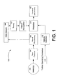
- FIG. 1 is a block diagram illustrating an example automated gas turbine hardware failure detection system 100, according to example embodiments of the invention.
- the system 100 may include one or more sensor(s) 102 for measuring parameters and events associated with the turbine.
- the sensors 102 may include pyrometer sensors, emissivity sensors, temperature sensors, gas sensors, cameras, acoustical sensors, etc.
- one or more pyrometers may be positioned with respect to the upstream side row of turbine buckets so that it may measure temperature or emissivity of from the rotating turbine buckets.
- melted material from a failing component such as a nozzle
- the automated gas turbine hardware failure detection system 100 may include one or more data capture modules 104 that may be configured to receive and condition the parameter information measured by the sensors 102.
- the data capture modules 104 may include analog to digital converters, level shifting, filtering, calibration, power supplies, etc., for proper communication with the sensors 102 and/or for conditioning the signals that are received from the sensors 102.
- the data capture module(s) 104 may communicate with a signal-processing module 106.
- the signal-processing module 106 may further process the information received from the sensor(s) 102 via the data capture module(s) 104. For example, the signal-processing module 106 may average or filter the incoming data. In certain embodiments, the signal-processing module 106 may scale and/or format the data for storage in a data array 108.
- the data stored in the data array(s) 108 may be utilized by the timing module 110, and/or the pattern recognition module 112 to detect changes in the various incoming parameters and to identify certain time-dependent events associated with the turbine that may indicative of failure modes.
- the pattern recognition module 112 may be configured to, or programmed to analyze information in the data array(s) 108.
- the pattern recognition module 112 may be configured to utilize information from the timing module 110 for analyzing measurement data as a function of time. Additional examples involving the pattern recognition aspect of the invention will be further discussed with reference to FIG. 2 below.
- a stability detection 116 module may monitor turbine operating parameters 114 to enable a protection module 118 only after certain operating criteria are met.
- the stability detection module 116 may monitor turbine operation parameters 114 to determine if the turbine has reached steady state operation, and/or if other criteria are met.
- the stability detection module 116 may inhibit the protection module 118 and keep it from initiating a shutdown of the system via the turbine controls 120 until after the stability criteria are met, and certain event criteria have been met. For example, shutdown may be initiated upon detection of the event and after fuel flow or airflow associated with the turbine has initialized or stabilized.
- a change in temperature or emissivity of the turbine buckets may signal an event that (either alone or combined with other events, such as changes in the detected NOx level, or changes in the combustion acoustic properties, for example) may be utilized to determine a possible impending failure so that preemptive action can be taken.
- FIG. 2 depicts an illustrative graph of example combustion event timing according to an example embodiment of the invention.
- This graph 200 shows and example sensor response 202 as a function of time 204.
- the sensor output may be in response to temperature or some other measured parameter associated with the turbine.
- the sensor may output a certain initialization response 206 over an initialization period 208.
- the stability detection aspect of the invention (such as 116 in FIG. 1 ), may disable the protection and/or shutdown features (such as 118 and 120 respectively in FIG. 1 ) until after the initialization time 208.
- the one or more sensors may sense parameter changes (such as rising temperature, changing NOx, etc.).
- the automated gas turbine hardware failure detection system (such as 100 in FIG. 1 ) may then analyze and classify the changing parameter as an event 210, provided that certain criteria are met. For example, an event may be classified by amplitude 212, sustained level 214, and/or sustained time 216.
- monitoring a parameter associated with the turbine may include determining a moving average of the parameter over at least one time duration.
- an event that may trigger a shutdown after stabilization is a measured temperature increase in a turbine bucket of greater than about 5 degrees Fahrenheit over less than about 10 minutes.
- an event that may trigger a shutdown after stabilization is an exhaust NOx increase of greater than about 2 ppm (parts per million) over less than about 10 minutes.
- shutdown of the turbine may be initiated when an event has been detected and a difference between the current monitored parameter and a stored past monitored parameter is sustained above about 25% of a limit associated with the event for greater than about 1 minute.
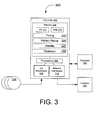
- FIG. 3 depicts a block diagram of an automated gas turbine hardware failure detection control system 300, according to an example embodiment of the invention.
- the system 300 may include a controller 302, which may include a memory 304, one or more processors 306, and input/output interfaces 308.
- the controller 302 may include one or more network interfaces 310.
- the memory 304 may include an operating system 312, data 314, and various special purpose modules.
- the data 314 may include data arrays, such as 108 in FIG. 1 .
- the control system 300 may include a database 316 for data storage and retrieval.
- the memory 302 may include a timing module, such as 110 in FIG. 1 , configured or programmed to carry out operations including time stamping, formatting data 314, and performing operations relating to time functions.
- a clock may be utilized in the timing module 318, similar to 110 in FIG. 1 .
- the memory 304 may also include a pattern recognition module 320, similar to 112 in FIG. 1 . This module may be configured or programmed to detect changes in the various incoming parameters and to identify certain time-dependent events associated with the turbine that may indicative of failure modes.
- the pattern recognition module 320 may be configured to, or programmed to analyze information in the data array(s) 108.
- the pattern recognition module 320 may be configured to utilize information from the timing module 318 for analyzing measurement data as a function of time. In certain embodiments of the invention, the pattern recognition module 320 may carry out functions, as described with reference to FIG. 2 . For example, the pattern recognition module 320 may analyze and classify changing parameter as an event if certain criteria are met.
- the memory 304 may include a protection module 324, which can be similar to 118 in FIG. 1 .
- the protection module 324 may receive information from the pattern recognition module 112, and may utilize this information in conjunction with instructions from a stability module 322, which can be similar to 116 in FIG. 1 , to initiate shutdown of the turbine when certain event criteria are met.
- the stability module 322 may monitor turbine operation parameters, such as 114 in FIG. 1 , to determine if the turbine has reached steady state operation, and/or if other criteria are met.
- the stability module 322 may inhibit the protection module 324 and keep it from initiating a shutdown of the system via the turbine controls 328, similar to 120 in FIG. 1 , until after the stability criteria are met, and certain event criteria have been met. For example, shutdown may be initiated upon detection of the event and after fuel flow or airflow associated with the turbine has initialized or stabilized.
- the method 400 starts in block 402, where according to an example embodiment of the invention, the method 400 includes monitoring a parameter associated with the turbine, wherein the parameter comprises at least one turbine bucket temperature. In block 404, the method 400 includes detecting an event associated with operation of the turbine, wherein the event is based at least in part on the monitored parameter. In block 406, the method 400 includes initiating shutdown of the turbine upon detection of the event wherein the monitored parameter is above a predetermined value for at least a predetermined time duration. The method 400 ends after block 406.
- example embodiments of the invention can provide the technical effects of creating certain systems, methods, and apparatus that provide detection of events associated with a turbine.
- Example embodiments of the invention can provide the further technical effects of providing systems, methods, and apparatus for classifying the detected events as being associated with a failure mode or a probable failure mode associated with the turbine.
- Example embodiments of the invention can provide the further technical effects of providing systems, methods, and apparatus for initiating automatic shutdown of a turbine if certain events are detected, thereby preempting further damage in the turbine, and in some cases, avoiding catastrophic failure of turbine.
- the automated gas turbine hardware failure detection system 100 and/or the automated gas turbine hardware failure detection control system 300 may include any number of hardware and/or software applications that are executed to facilitate any of the operations.
- one or more I/O interfaces may facilitate communication between the automated combustion hardware failure detection and shutdown system 100 and/or the automated gas turbine hardware failure detection control system 300, and one or more input/output devices.
- a universal serial bus port, a serial port, a disk drive, a CD-ROM drive, and/or one or more user interface devices such as a display, keyboard, keypad, mouse, control panel, touch screen display, microphone, etc., may facilitate user interaction with the automated gas turbine hardware failure detection system 100 and/or the automated gas turbine hardware failure detection control system 300.
- the one or more I/O interfaces may be utilized to receive or collect data and/or user instructions from a wide variety of input devices. Received data may be processed by one or more computer processors as desired in various embodiments of the invention and/or stored in one or more memory devices.
- One or more network interfaces may facilitate connection of the automated gas turbine hardware failure detection system 100 and/or the automated gas turbine hardware failure detection control system 300 inputs and outputs to one or more suitable networks and/or connections; for example, the connections that facilitate communication with any number of sensors associated with the system.
- the one or more network interfaces may further facilitate connection to one or more suitable networks; for example, a local area network, a wide area network, the Internet, a cellular network, a radio frequency network, a Bluetooth TM enabled network, a Wi-FiTM enabled network, a satellite-based network, any wired network, any wireless network, etc., for communication with external devices and/or systems.
- embodiments of the invention may include the automated gas turbine hardware failure detection system 100 and/or the automated gas turbine hardware failure detection control system 300 with more or less of the components illustrated in FIGs. 1 and 3 .
- These computer-executable program instructions may be loaded onto a general-purpose computer, a special-purpose computer, a processor, or other programmable data processing apparatus to produce a particular machine, such that the instructions that execute on the computer, processor, or other programmable data processing apparatus create means for implementing one or more functions specified in the flow diagram block or blocks.
- These computer program instructions may also be stored in a computer-readable memory that can direct a computer or other programmable data processing apparatus to function in a particular manner, such that the instructions stored in the computer-readable memory produce an article of manufacture including instruction means that implement one or more functions specified in the flow diagram block or blocks.
- embodiments of the invention may provide for a computer program product, comprising a computer-usable medium having a computer-readable program code or program instructions embodied therein, said computer-readable program code adapted to be executed to implement one or more functions specified in the flow diagram block or blocks.
- the computer program instructions may also be loaded onto a computer or other programmable data processing apparatus to cause a series of operational elements or steps to be performed on the computer or other programmable apparatus to produce a computer-implemented process such that the instructions that execute on the computer or other programmable apparatus provide elements or steps for implementing the functions specified in the flow diagram block or blocks.
- blocks of the block diagrams and flow diagrams support combinations of means for performing the specified functions, combinations of elements or steps for performing the specified functions and program instruction means for performing the specified functions. It will also be understood that each block of the block diagrams and flow diagrams, and combinations of blocks in the block diagrams and flow diagrams, can be implemented by special-purpose, hardware-based computer systems that perform the specified functions, elements or steps, or combinations of special-purpose hardware and computer instructions.
Landscapes
- Engineering & Computer Science (AREA)
- Mechanical Engineering (AREA)
- General Engineering & Computer Science (AREA)
- Chemical & Material Sciences (AREA)
- Combustion & Propulsion (AREA)
- Testing And Monitoring For Control Systems (AREA)
Abstract
Description
- This invention generally relates to gas turbines, and in particular, to detecting failure in gas turbine hardware.
- Gas turbines are typically large, complex machines with expensive parts that must withstand challenging environmental conditions. Building, maintaining, and operating these machines often requires a significant capital investment, and therefore, steps are often taken to ramp-up and ramp-down the turbines under careful control, in order to protect the capital investment, and operate the turbine within safe limits.
- History has shown, however, that certain combustion failures can occur over a long period of time, and such failures may eventually result in catastrophic failure if they are not detected in time to ramp-down the turbine and perform corrective action. Furthermore, some failures may not be detectable in terms of usual monitoring parameters such as power output, grid frequency, or combustion modes.
- Some or all of the above needs may be addressed by certain embodiments of the invention. Certain embodiments of the invention may include systems, methods, and apparatus for detecting failure in gas turbine hardware.
- According to an example embodiment of the invention, a method for detecting a failure in a gas turbine is provided. The method can include monitoring a parameter associated with the turbine, wherein the monitored parameter comprises at least one turbine bucket temperature, detecting an event associated with operation of the turbine, wherein the event is based at least in part on the monitored parameter, and initiating shutdown of the turbine upon detection of the event wherein the monitored parameter is above a predetermined value for at least a predetermined time duration.
- According to another example embodiment, a system is provided for detecting failure. The system includes a gas turbine, at least one sensor for measuring a parameter associated with the turbine, wherein the parameter comprises at least one turbine bucket temperature. The system also includes at least one processor configured or programmed to receive and monitor the measured parameter from the at least one sensor, detect an event associated with operation of the turbine, wherein the event is based at least in part on the monitored parameter, and initiate shutdown of the turbine upon detection of the event wherein the monitored parameter is above a predetermined value for at least a predetermined time duration.
- According to another example embodiment, an apparatus is provided for detecting failure in a turbine. The apparatus includes at least one processor configured to receive and monitor a measured parameter from at least one sensor, wherein the measured parameter comprises at least one turbine bucket temperature, detect an event associated with operation of the turbine, wherein the event is based at least in part on the monitored parameter, and initiate shutdown of the turbine upon detection of the event wherein the monitored parameter is above a predetermined value for at least a predetermined time duration.
- Other embodiments and aspects of the invention are described in detail herein and are considered a part of the claimed invention. Other embodiments and aspects can be understood with reference to the following detailed description, accompanying drawings, and claims.
- Reference will now be made to the accompanying tables and drawings, which are not necessarily drawn to scale, and wherein:
-
FIG. 1 is a block diagram of an illustrative automated combustion hardware failure detection and shutdown system, according to an example embodiment of the invention. -
FIG. 2 is an example graph illustrative of combustion event timing, according to an example embodiment of the invention. -
FIG. 3 is a block diagram of an automated gas turbine hardware failure detection control system, according to an example embodiment of the invention. -
FIG. 4 is a flow diagram of an example method according to an example embodiment of the invention. - Embodiments of the invention will be described more fully hereinafter with reference to the accompanying drawings, in which embodiments of the invention are shown. This invention may, however, be embodied in many different forms and should not be construed as limited to the embodiments set forth herein; rather, these embodiments are provided so that this disclosure will be thorough and complete, and will fully convey the scope of the invention to those skilled in the art. Like numbers refer to like elements throughout. Certain embodiments of the invention may enable automated hardware failure detection in a gas turbine. According to example embodiments, certain components in the hot gas path (HGP) of a turbine may be monitored to detect problems that could lead to a turbine failure.
- Certain failure modes in a gas combustor can occur because of gradual failure or deterioration of components over hours, days, or weeks. According to example embodiments of the invention, systems, methods, and apparatus are provided to detect certain events that may be associated with an impending failure. In certain example embodiments, the event detection may be utilized to automatically shutdown a turbine. In accordance with certain embodiments, the detection and shutdown may limit further damage, and in certain cases, may eliminate a catastrophic (and expensive) turbine failure.
- An example event that may correlate with a turbine failure (if left unchecked) is a combustor nozzle failure. For example, the combustor nozzle may be subjected to high temperatures and under certain conditions; a portion of the nozzle may begin to melt. This can create a relatively dangerous and sometimes hard to detect situation, which if left unchecked, could trigger extensive damage in other components in the hot gas path. For example, pieces of the failing nozzle may break off and damage other components such as rotating turbine blades or buckets, which may in turn break off and damage other components associated with the turbine. According to example embodiments pyrometers and other sensing devices, may be utilized to, for example, measure parameters such as bucket emissivity, acoustical energy, and/or exhaust NOx levels. According to example embodiments, monitoring and analysis of the measured parameter(s) may enable the control system to identify certain events and shut down the unit, thus preventing extensive damage. Certain embodiments of the invention may be applied to gas turbines and turbine systems for power generation applications. Embodiments of the invention may also be applied to turbines associated with engines, such as those used in aircraft and other vehicles.
- According to example embodiments of the invention, various sensors, signal processors, pattern recognition modules, and controllers for detecting and responding to certain events associated with a failure will now be described with reference to the accompanying figures.
-
FIG. 1 is a block diagram illustrating an example automated gas turbine hardwarefailure detection system 100, according to example embodiments of the invention. Thesystem 100 may include one or more sensor(s) 102 for measuring parameters and events associated with the turbine. In an example embodiment, thesensors 102 may include pyrometer sensors, emissivity sensors, temperature sensors, gas sensors, cameras, acoustical sensors, etc. For example, and according to an example embodiment, one or more pyrometers may be positioned with respect to the upstream side row of turbine buckets so that it may measure temperature or emissivity of from the rotating turbine buckets. In accordance with an example embodiment of the invention, melted material from a failing component (such as a nozzle) may collect on the bucket surface, and may cause a detectable change in the emissivity or temperature of the bucket surface. - According to an example embodiment of the invention, the automated gas turbine hardware
failure detection system 100 may include one or moredata capture modules 104 that may be configured to receive and condition the parameter information measured by thesensors 102. Thedata capture modules 104 may include analog to digital converters, level shifting, filtering, calibration, power supplies, etc., for proper communication with thesensors 102 and/or for conditioning the signals that are received from thesensors 102. - According to an example embodiment, the data capture module(s) 104 may communicate with a signal-
processing module 106. In an example embodiment the signal-processing module 106 may further process the information received from the sensor(s) 102 via the data capture module(s) 104. For example, the signal-processing module 106 may average or filter the incoming data. In certain embodiments, the signal-processing module 106 may scale and/or format the data for storage in adata array 108. - In an example embodiment, the data stored in the data array(s) 108 may be utilized by the
timing module 110, and/or thepattern recognition module 112 to detect changes in the various incoming parameters and to identify certain time-dependent events associated with the turbine that may indicative of failure modes. For example, in an embodiment of the invention, thepattern recognition module 112 may be configured to, or programmed to analyze information in the data array(s) 108. In another example embodiment, thepattern recognition module 112 may be configured to utilize information from thetiming module 110 for analyzing measurement data as a function of time. Additional examples involving the pattern recognition aspect of the invention will be further discussed with reference toFIG. 2 below. - In certain example embodiments of the invention, some of the various operational modes of the gas turbine may be more suitable than others for determining events associated with possible failure. For example, when the turbine is being ramped-up, the measurable parameters (temperature, exhaust gasses, airflow, fuel flow, etc.) may be fluctuating normally, but may cause a false alarm or shutdown of the system. Therefore, according to an aspect of one embodiment of the invention, a
stability detection 116 module may monitorturbine operating parameters 114 to enable aprotection module 118 only after certain operating criteria are met. For example, thestability detection module 116 may monitorturbine operation parameters 114 to determine if the turbine has reached steady state operation, and/or if other criteria are met. In accordance with an example embodiment of the invention, thestability detection module 116 may inhibit theprotection module 118 and keep it from initiating a shutdown of the system via theturbine controls 120 until after the stability criteria are met, and certain event criteria have been met. For example, shutdown may be initiated upon detection of the event and after fuel flow or airflow associated with the turbine has initialized or stabilized. - According to example embodiments of the invention, a change in temperature or emissivity of the turbine buckets may signal an event that (either alone or combined with other events, such as changes in the detected NOx level, or changes in the combustion acoustic properties, for example) may be utilized to determine a possible impending failure so that preemptive action can be taken.
-
FIG. 2 depicts an illustrative graph of example combustion event timing according to an example embodiment of the invention. Thisgraph 200 shows andexample sensor response 202 as a function oftime 204. The sensor output may be in response to temperature or some other measured parameter associated with the turbine. In an example embodiment, the sensor may output acertain initialization response 206 over aninitialization period 208. In an example embodiment of the invention, and as described above, the stability detection aspect of the invention (such as 116 inFIG. 1 ), may disable the protection and/or shutdown features (such as 118 and 120 respectively inFIG. 1 ) until after theinitialization time 208. - According to an example embodiment of the invention, the one or more sensors may sense parameter changes (such as rising temperature, changing NOx, etc.). The automated gas turbine hardware failure detection system (such as 100 in
FIG. 1 ) may then analyze and classify the changing parameter as anevent 210, provided that certain criteria are met. For example, an event may be classified byamplitude 212,sustained level 214, and/orsustained time 216. In accordance with certain example embodiments of the invention, monitoring a parameter associated with the turbine may include determining a moving average of the parameter over at least one time duration. In an example embodiment, an event that may trigger a shutdown after stabilization is a measured temperature increase in a turbine bucket of greater than about 5 degrees Fahrenheit over less than about 10 minutes. According to another example embodiment, an event that may trigger a shutdown after stabilization is an exhaust NOx increase of greater than about 2 ppm (parts per million) over less than about 10 minutes. - According to example embodiments of the invention, shutdown of the turbine may be initiated when an event has been detected and a difference between the current monitored parameter and a stored past monitored parameter is sustained above about 25% of a limit associated with the event for greater than about 1 minute.
-
FIG. 3 depicts a block diagram of an automated gas turbine hardware failuredetection control system 300, according to an example embodiment of the invention. According to an example embodiment, thesystem 300 may include acontroller 302, which may include amemory 304, one ormore processors 306, and input/output interfaces 308. In certain example embodiments, thecontroller 302 may include one or more network interfaces 310. In an example embodiment, thememory 304 may include anoperating system 312,data 314, and various special purpose modules. Thedata 314 may include data arrays, such as 108 inFIG. 1 . According to an example embodiment, thecontrol system 300 may include adatabase 316 for data storage and retrieval. - In an example embodiment, the
memory 302 may include a timing module, such as 110 inFIG. 1 , configured or programmed to carry out operations including time stamping, formattingdata 314, and performing operations relating to time functions. In certain embodiments, a clock may be utilized in thetiming module 318, similar to 110 inFIG. 1 . According to an example embodiment, thememory 304 may also include apattern recognition module 320, similar to 112 inFIG. 1 . This module may be configured or programmed to detect changes in the various incoming parameters and to identify certain time-dependent events associated with the turbine that may indicative of failure modes. For example, in an embodiment of the invention, thepattern recognition module 320 may be configured to, or programmed to analyze information in the data array(s) 108. In another example embodiment, thepattern recognition module 320 may be configured to utilize information from thetiming module 318 for analyzing measurement data as a function of time. In certain embodiments of the invention, thepattern recognition module 320 may carry out functions, as described with reference toFIG. 2 . For example, thepattern recognition module 320 may analyze and classify changing parameter as an event if certain criteria are met. - According to an example embodiment, and with continued reference to
FIG. 3 , thememory 304 may include aprotection module 324, which can be similar to 118 inFIG. 1 . Theprotection module 324 may receive information from thepattern recognition module 112, and may utilize this information in conjunction with instructions from astability module 322, which can be similar to 116 inFIG. 1 , to initiate shutdown of the turbine when certain event criteria are met. For example, thestability module 322 may monitor turbine operation parameters, such as 114 inFIG. 1 , to determine if the turbine has reached steady state operation, and/or if other criteria are met. In accordance with an example embodiment of the invention, thestability module 322 may inhibit theprotection module 324 and keep it from initiating a shutdown of the system via the turbine controls 328, similar to 120 inFIG. 1 , until after the stability criteria are met, and certain event criteria have been met. For example, shutdown may be initiated upon detection of the event and after fuel flow or airflow associated with the turbine has initialized or stabilized. - An example method for detecting a failure in a gas turbine will now be described with reference to the flowchart of
FIG. 4 . Themethod 400 starts inblock 402, where according to an example embodiment of the invention, themethod 400 includes monitoring a parameter associated with the turbine, wherein the parameter comprises at least one turbine bucket temperature. Inblock 404, themethod 400 includes detecting an event associated with operation of the turbine, wherein the event is based at least in part on the monitored parameter. Inblock 406, themethod 400 includes initiating shutdown of the turbine upon detection of the event wherein the monitored parameter is above a predetermined value for at least a predetermined time duration. Themethod 400 ends afterblock 406. - Accordingly, example embodiments of the invention can provide the technical effects of creating certain systems, methods, and apparatus that provide detection of events associated with a turbine. Example embodiments of the invention can provide the further technical effects of providing systems, methods, and apparatus for classifying the detected events as being associated with a failure mode or a probable failure mode associated with the turbine. Example embodiments of the invention can provide the further technical effects of providing systems, methods, and apparatus for initiating automatic shutdown of a turbine if certain events are detected, thereby preempting further damage in the turbine, and in some cases, avoiding catastrophic failure of turbine.
- In example embodiments of the invention, the automated gas turbine hardware
failure detection system 100 and/or the automated gas turbine hardware failuredetection control system 300 may include any number of hardware and/or software applications that are executed to facilitate any of the operations. - In example embodiments, one or more I/O interfaces may facilitate communication between the automated combustion hardware failure detection and
shutdown system 100 and/or the automated gas turbine hardware failuredetection control system 300, and one or more input/output devices. For example, a universal serial bus port, a serial port, a disk drive, a CD-ROM drive, and/or one or more user interface devices, such as a display, keyboard, keypad, mouse, control panel, touch screen display, microphone, etc., may facilitate user interaction with the automated gas turbine hardwarefailure detection system 100 and/or the automated gas turbine hardware failuredetection control system 300. The one or more I/O interfaces may be utilized to receive or collect data and/or user instructions from a wide variety of input devices. Received data may be processed by one or more computer processors as desired in various embodiments of the invention and/or stored in one or more memory devices. - One or more network interfaces may facilitate connection of the automated gas turbine hardware
failure detection system 100 and/or the automated gas turbine hardware failuredetection control system 300 inputs and outputs to one or more suitable networks and/or connections; for example, the connections that facilitate communication with any number of sensors associated with the system. The one or more network interfaces may further facilitate connection to one or more suitable networks; for example, a local area network, a wide area network, the Internet, a cellular network, a radio frequency network, a BluetoothTM enabled network, a Wi-Fi™ enabled network, a satellite-based network, any wired network, any wireless network, etc., for communication with external devices and/or systems. - As desired, embodiments of the invention may include the automated gas turbine hardware
failure detection system 100 and/or the automated gas turbine hardware failuredetection control system 300 with more or less of the components illustrated inFIGs. 1 and3 . - The invention is described above with reference to block and flow diagrams of systems, methods, apparatuses, and/or computer program products according to example embodiments of the invention. It will be understood that one or more blocks of the block diagrams and flow diagrams, and combinations of blocks in the block diagrams and flow diagrams, respectively, can be implemented by computer-executable program instructions. Likewise, some blocks of the block diagrams and flow diagrams may not necessarily need to be performed in the order presented, or may not necessarily need to be performed at all, according to some embodiments of the invention.
- These computer-executable program instructions may be loaded onto a general-purpose computer, a special-purpose computer, a processor, or other programmable data processing apparatus to produce a particular machine, such that the instructions that execute on the computer, processor, or other programmable data processing apparatus create means for implementing one or more functions specified in the flow diagram block or blocks. These computer program instructions may also be stored in a computer-readable memory that can direct a computer or other programmable data processing apparatus to function in a particular manner, such that the instructions stored in the computer-readable memory produce an article of manufacture including instruction means that implement one or more functions specified in the flow diagram block or blocks. As an example, embodiments of the invention may provide for a computer program product, comprising a computer-usable medium having a computer-readable program code or program instructions embodied therein, said computer-readable program code adapted to be executed to implement one or more functions specified in the flow diagram block or blocks. The computer program instructions may also be loaded onto a computer or other programmable data processing apparatus to cause a series of operational elements or steps to be performed on the computer or other programmable apparatus to produce a computer-implemented process such that the instructions that execute on the computer or other programmable apparatus provide elements or steps for implementing the functions specified in the flow diagram block or blocks.
- Accordingly, blocks of the block diagrams and flow diagrams support combinations of means for performing the specified functions, combinations of elements or steps for performing the specified functions and program instruction means for performing the specified functions. It will also be understood that each block of the block diagrams and flow diagrams, and combinations of blocks in the block diagrams and flow diagrams, can be implemented by special-purpose, hardware-based computer systems that perform the specified functions, elements or steps, or combinations of special-purpose hardware and computer instructions.
- While the invention has been described in connection with what is presently considered to be the most practical and various embodiments, it is to be understood that the invention is not to be limited to the disclosed embodiments, but on the contrary, is intended to cover various modifications and equivalent arrangements included within the scope of the appended claims. Although specific terms are employed herein, they are used in a generic and descriptive sense only and not for purposes of limitation.
- This written description uses examples to disclose the invention, including the preferred mode, and also to enable any person skilled in the art to practice the invention, including making and using any devices or systems and performing any incorporated methods. The patentable scope of the invention is defined in the claims, and may include other examples that occur to those skilled in the art. Such other examples are intended to be within the scope of the claims if they have structural elements that do not differ from the literal language of the claims, or if they include equivalent structural elements with insubstantial differences from the literal language of the claims.
- Various aspects and embodiments of the present invention are defined by the following numbered clauses:
- 1. A method for detecting a failure in a gas turbine comprising:
- monitoring a parameter associated with the turbine, wherein the monitored parameter comprises at least one turbine bucket temperature;
- detecting an event associated with operation of the turbine, wherein the event is based at least in part on the monitored parameter; and
- initiating shutdown of the turbine upon detection of the event wherein the monitored parameter is above a predetermined value for at least a predetermined time duration.
- 2. The method of clause 1, wherein the monitored parameter associated with the turbine combustor further comprises at least one of: bucket emissivity, acoustical energy, or exhaust NOx level.
- 3. The method of any preceding clause, wherein initiating shutdown is performed upon detection of the event after fuel flow or airflow associated with the turbine has initialized or stabilized.
- 4. The method of any preceding clause, wherein monitoring a parameter associated with the turbine comprises determining a moving average of the parameter over at least one time duration.
- 5. The method of any preceding clause, wherein an event comprises a turbine bucket temperature increase of greater than about 5 degrees Fahrenheit over less than about 10 minutes
- 6. The method of any preceding clause, wherein an event comprises an exhaust NOx increase of greater than about 2 ppm over less than about 10 minutes
- 7. The method of any preceding clause, wherein initiating shutdown of the turbine occurs when an event has been detected and a difference between the current monitored parameter and a stored past monitored parameter is sustained above about 25% of a limit associated with the event for greater than about 1 minute.
- 8. A system for detecting failure comprising:
- a gas turbine;
- at least one sensor for measuring a parameter associated with the turbine, wherein the measured parameter comprises at least one turbine bucket temperature;
- at least one processor configured to:
- receive and monitor the measured parameter from the at least one sensor;
- detect an event associated with operation of the turbine, wherein the event is based at least in part on the monitored parameter; and
- initiate shutdown of the turbine upon detection of the event wherein the monitored parameter is above a predetermined value for at least a predetermined time duration.
- 9. The system of any preceding clause, wherein the at least one sensor is further operable to measure one or more of bucket emissivity, acoustical energy, or exhaust NOx level.
- 10. The system of any preceding clause, wherein the at least one processor is further configured to initiate shutdown upon detection of the event after fuel flow or airflow associated with the turbine has initialized or stabilized.
- 11. The system of any preceding clause, wherein the at least one processor is configured for receiving and monitoring from the at least one sensor, the measured parameter associated with the turbine, wherein monitoring comprises determining a moving average of the measured parameter over at least one time duration.
- 12. The system of any preceding clause, wherein an event comprises a turbine bucket temperature increase of greater than about 5 degrees Fahrenheit over less than about 10 minutes
- 13. The system of any preceding clause, wherein an event comprises an exhaust NOx increase of greater than about 2 ppm over less than about 10 minutes
- 14. The system of any preceding clause, wherein initiating shutdown of the turbine occurs when an event has been detected and a difference between the current monitored parameter and a stored past monitored parameter is sustained above about 25%of a limit associated with the event for greater than about 1 minute.
- 15. An apparatus for detecting failure in a turbine comprising:
- at least one processor configured to:
- receive and monitor a measured parameter from at least one sensor, wherein the measured parameter comprises at least one turbine bucket temperature;
- detect an event associated with operation of the turbine, wherein the event is based at least in part on the monitored parameter; and
- initiate shutdown of the turbine upon detection of the event wherein the monitored parameter is above a predetermined value for at least a predetermined time duration.
- at least one processor configured to:
- 16. The apparatus of any preceding clause, wherein the at least one processor is configured to receive and monitor a measured parameter from the at least one sensor, wherein the measured parameter further comprises one or more of: bucket emissivity, acoustical energy, or exhaust NOx level.
- 17. The apparatus of any preceding clause, wherein the at least one processor is further configured to initiate shutdown upon detection of the event after fuel flow or airflow associated with the turbine has initialized or stabilized.
- 18. The apparatus of any preceding clause, wherein the at least one processor is configured for receiving and monitoring from the at least one sensor, the measured parameter associated with the turbine, wherein monitoring comprises determining a moving average of the measured parameter over at least one time duration.
- 19. The apparatus of any preceding clause, wherein the at least one processor is further configured to detect an event associated with the operation of the turbine, wherein an event comprises a turbine bucket temperature increase of greater than about 5 degrees Fahrenheit or an exhaust NOx increase of greater than about 2 ppm over less than about 10 minutes.
- 20. The apparatus of any preceding clause, wherein initiating shutdown of the turbine occurs when an event has been detected and a difference between the current monitored parameter and a stored past monitored parameter is sustained above about 25% of a limit associated with the event for greater than about 1 minute.
Claims (10)
- A method (400) for detecting a failure in a gas turbine comprising:monitoring (402) a parameter associated with the turbine, wherein the monitored parameter comprises at least one turbine bucket temperature;detecting (404) an event associated with operation of the turbine, wherein the event is based at least in part on the monitored parameter; andinitiating shutdown (406) of the turbine upon detection of the event wherein the monitored parameter is above a predetermined value for at least a predetermined time duration.
- The method (400) of claim 1, wherein the monitored parameter associated with the turbine combustor further comprises at least one of: bucket emissivity, acoustical energy, or exhaust NOx level.
- The method (400) of any preceding claim, wherein initiating shutdown is performed upon detection of the event after fuel flow or airflow associated with the turbine has initialized or stabilized.
- The method (400) of any preceding claim, wherein monitoring a parameter associated with the turbine comprises determining a moving average of the parameter over at least one time duration.
- The method (400) of any preceding claim, wherein an event comprises a turbine bucket temperature increase of greater than about 5 degrees Fahrenheit over less than about 10 minutes.
- The method (400) of any preceding claim, wherein an event comprises an exhaust NOx increase of greater than about 2 ppm over less than about 10 minutes.
- The method (400) of any preceding claim, wherein initiating shutdown of the turbine occurs when an event has been detected and a difference between the current monitored parameter and a stored past monitored parameter is sustained above about 25% of a limit associated with the event for greater than about 1 minute.
- A system (100) for detecting failure comprising:a gas turbine;at least one sensor (322) for measuring a parameter associated with the turbine, wherein the measured parameter comprises at least one turbine bucket temperature;at least one processor (306) configured to:receive and monitor the measured parameter from the at least one sensor (322);detect an event associated with operation of the turbine, wherein the event is based at least in part on the monitored parameter; andinitiate shutdown of the turbine upon detection of the event wherein the monitored parameter is above a predetermined value for at least a predetermined time duration.
- The system (100) of claim 8, wherein the at least one sensor (322) is further operable to measure one or more of: bucket emissivity, acoustical energy, or exhaust NOx level.
- The system (100) of claim 8 or claim 9, wherein the at least one processor (306) is further configured to detect an event associated with the operation of the turbine after fuel flow or airflow associated with the turbine has initialized or stabilized.
Applications Claiming Priority (1)
| Application Number | Priority Date | Filing Date | Title |
|---|---|---|---|
| US12/761,029 US8818684B2 (en) | 2010-04-15 | 2010-04-15 | Systems, methods, and apparatus for detecting failure in gas turbine hardware |
Publications (3)
| Publication Number | Publication Date |
|---|---|
| EP2378087A2 true EP2378087A2 (en) | 2011-10-19 |
| EP2378087A3 EP2378087A3 (en) | 2012-04-18 |
| EP2378087B1 EP2378087B1 (en) | 2019-08-28 |
Family
ID=43901471
Family Applications (1)
| Application Number | Title | Priority Date | Filing Date |
|---|---|---|---|
| EP11161755.1A Active EP2378087B1 (en) | 2010-04-15 | 2011-04-08 | System and method for detecting failure in gas turbine |
Country Status (3)
| Country | Link |
|---|---|
| US (1) | US8818684B2 (en) |
| EP (1) | EP2378087B1 (en) |
| JP (1) | JP5848882B2 (en) |
Families Citing this family (8)
| Publication number | Priority date | Publication date | Assignee | Title |
|---|---|---|---|---|
| JP4453764B2 (en) * | 2008-02-22 | 2010-04-21 | トヨタ自動車株式会社 | Vehicle diagnostic device, vehicle diagnostic system, and diagnostic method |
| US8818684B2 (en) * | 2010-04-15 | 2014-08-26 | General Electric Company | Systems, methods, and apparatus for detecting failure in gas turbine hardware |
| ITCO20120008A1 (en) | 2012-03-01 | 2013-09-02 | Nuovo Pignone Srl | METHOD AND SYSTEM FOR MONITORING THE CONDITION OF A GROUP OF PLANTS |
| US9476318B2 (en) * | 2013-09-03 | 2016-10-25 | General Electric Company | Systems and methods to monitor a rotating component |
| EP3061944A1 (en) * | 2015-02-26 | 2016-08-31 | General Electric Technology GmbH | Method for controlling the operation of a gas turbine with sequential combustion |
| US10371002B2 (en) | 2016-06-14 | 2019-08-06 | General Electric Company | Control system for a gas turbine engine |
| US10581665B2 (en) * | 2016-11-04 | 2020-03-03 | Nec Corporation | Content-aware anomaly detection and diagnosis |
| US20220179375A1 (en) * | 2020-12-04 | 2022-06-09 | Solar Turbines Incorporated | Human-machine interface with imaging application |
Family Cites Families (26)
| Publication number | Priority date | Publication date | Assignee | Title |
|---|---|---|---|---|
| US4249238A (en) * | 1978-05-24 | 1981-02-03 | The United States Of America As Represented By The Administrator Of The National Aeronautics And Space Administration | Apparatus for sensor failure detection and correction in a gas turbine engine control system |
| US4744670A (en) * | 1986-05-05 | 1988-05-17 | Honeywell, Inc. | Method and apparatus for monitoring the temperature of the propulsion gas at the inlet to a high-performance turbine wheel |
| JPH03138425A (en) * | 1989-10-25 | 1991-06-12 | Toshiba Corp | Gas turbine temperature protector |
| US5054996A (en) * | 1990-07-27 | 1991-10-08 | General Electric Company | Thermal linear actuator for rotor air flow control in a gas turbine |
| JP3484477B2 (en) * | 1993-03-16 | 2004-01-06 | 川崎重工業株式会社 | Temperature detection method and temperature detection device for gas turbine engine |
| JP3569000B2 (en) * | 1994-09-12 | 2004-09-22 | 株式会社東芝 | Gas turbine blade abnormality monitoring system |
| JPH08177530A (en) * | 1994-12-27 | 1996-07-09 | Toshiba Corp | Abnormality detecting device for gas turbine |
| JP3663608B2 (en) * | 1996-05-22 | 2005-06-22 | 石川島播磨重工業株式会社 | Gas turbine rotor blade fault diagnosis method and apparatus |
| US6526358B1 (en) * | 1999-10-01 | 2003-02-25 | General Electric Company | Model-based detection of leaks and blockages in fluid handling systems |
| JP3538670B2 (en) * | 2000-09-04 | 2004-06-14 | 川崎重工業株式会社 | Gas turbine operating state diagnosis method and diagnosis apparatus |
| US6579005B2 (en) * | 2000-12-28 | 2003-06-17 | General Electric Company | Utilization of pyrometer data to detect oxidation |
| CA2438353C (en) | 2001-06-18 | 2009-08-25 | Hitachi, Ltd. | Method of diagnosing gas turbine condition and system for diagnosing the same |
| US6952639B2 (en) * | 2002-11-12 | 2005-10-04 | General Electric Company | Method and system for temperature estimation of gas turbine combustion cans |
| EP1585889A2 (en) * | 2003-01-22 | 2005-10-19 | Vast Power Systems, Inc. | Thermodynamic cycles using thermal diluent |
| JP4346947B2 (en) * | 2003-04-25 | 2009-10-21 | 三菱重工業株式会社 | Equipment abnormality monitoring device, gas turbine abnormality monitoring device, gas turbine equipment and combined power generation equipment |
| JP3881980B2 (en) | 2003-12-02 | 2007-02-14 | 三菱重工業株式会社 | Gas turbine protection equipment |
| US7269953B2 (en) * | 2004-08-27 | 2007-09-18 | Siemens Power Generation, Inc. | Method of controlling a power generation system |
| US7278266B2 (en) * | 2004-08-31 | 2007-10-09 | General Electric Company | Methods and apparatus for gas turbine engine lean blowout avoidance |
| US7286923B2 (en) * | 2005-09-30 | 2007-10-23 | General Electric Company | System and method for estimating turbine engine deterioration rate with noisy data |
| US7603222B2 (en) * | 2005-11-18 | 2009-10-13 | General Electric Company | Sensor diagnostics using embedded model quality parameters |
| JP4801452B2 (en) * | 2006-01-19 | 2011-10-26 | 三菱重工業株式会社 | Abnormality monitoring method and apparatus for gas turbine |
| US8818683B2 (en) * | 2006-04-21 | 2014-08-26 | General Electric Company | Method and apparatus for operating a gas turbine engine |
| US7432505B2 (en) | 2006-05-04 | 2008-10-07 | Siemens Power Generation, Inc. | Infrared-based method and apparatus for online detection of cracks in steam turbine components |
| US7734443B2 (en) * | 2007-08-23 | 2010-06-08 | General Electric Company | System and method for prediction of gas turbine trips due to thermocouple failures |
| US20090228230A1 (en) * | 2008-03-06 | 2009-09-10 | General Electric Company | System and method for real-time detection of gas turbine or aircraft engine blade problems |
| US8818684B2 (en) * | 2010-04-15 | 2014-08-26 | General Electric Company | Systems, methods, and apparatus for detecting failure in gas turbine hardware |
-
2010
- 2010-04-15 US US12/761,029 patent/US8818684B2/en active Active
-
2011
- 2011-04-08 EP EP11161755.1A patent/EP2378087B1/en active Active
- 2011-04-12 JP JP2011087832A patent/JP5848882B2/en not_active Expired - Fee Related
Non-Patent Citations (1)
| Title |
|---|
| None |
Also Published As
| Publication number | Publication date |
|---|---|
| US20110257864A1 (en) | 2011-10-20 |
| JP5848882B2 (en) | 2016-01-27 |
| JP2011226476A (en) | 2011-11-10 |
| US8818684B2 (en) | 2014-08-26 |
| EP2378087B1 (en) | 2019-08-28 |
| CN102252850A (en) | 2011-11-23 |
| EP2378087A3 (en) | 2012-04-18 |
Similar Documents
| Publication | Publication Date | Title |
|---|---|---|
| US8818684B2 (en) | Systems, methods, and apparatus for detecting failure in gas turbine hardware | |
| EP3399376B1 (en) | Plant-abnormality-monitoring method and computer program for plant abnormality monitoring | |
| CA2218450C (en) | Diagnostic trend analysis | |
| US9672664B2 (en) | Systems and methods for monitoring protection devices of an industrial machine | |
| US9791351B2 (en) | Gas turbine combustion profile monitoring | |
| EP3103968A1 (en) | Systems and methods for monitoring a compressor | |
| US10767507B2 (en) | Foreign object debris trending concept and design | |
| EP3173890B1 (en) | Fault detection methods and systems | |
| US11434833B2 (en) | Methods and systems for detection of control sensor override | |
| EP2407642B1 (en) | System and method for determining steady state conditions in a gas turbine | |
| US11054340B2 (en) | Parametric trending architecture concept and design | |
| EP3376004B1 (en) | Method of detecting flameout in a combustor and turbine system | |
| JP5675456B2 (en) | Monitoring device, gas turbine plant, and gas turbine monitoring method | |
| CN102252850B (en) | For detecting the system of the fault in gas turbine hardware, method and apparatus | |
| US20210123834A1 (en) | Method of detecting flameout in a combustor and turbine system | |
| EP3324258A1 (en) | Modeling to detect gas turbine anomalies |
Legal Events
| Date | Code | Title | Description |
|---|---|---|---|
| AK | Designated contracting states |
Kind code of ref document: A2 Designated state(s): AL AT BE BG CH CY CZ DE DK EE ES FI FR GB GR HR HU IE IS IT LI LT LU LV MC MK MT NL NO PL PT RO RS SE SI SK SM TR |
|
| AX | Request for extension of the european patent |
Extension state: BA ME |
|
| PUAI | Public reference made under article 153(3) epc to a published international application that has entered the european phase |
Free format text: ORIGINAL CODE: 0009012 |
|
| PUAL | Search report despatched |
Free format text: ORIGINAL CODE: 0009013 |
|
| AK | Designated contracting states |
Kind code of ref document: A3 Designated state(s): AL AT BE BG CH CY CZ DE DK EE ES FI FR GB GR HR HU IE IS IT LI LT LU LV MC MK MT NL NO PL PT RO RS SE SI SK SM TR |
|
| AX | Request for extension of the european patent |
Extension state: BA ME |
|
| RIC1 | Information provided on ipc code assigned before grant |
Ipc: F02C 9/00 20060101ALI20120313BHEP Ipc: F01D 21/00 20060101AFI20120313BHEP |
|
| 17P | Request for examination filed |
Effective date: 20121018 |
|
| STAA | Information on the status of an ep patent application or granted ep patent |
Free format text: STATUS: EXAMINATION IS IN PROGRESS |
|
| 17Q | First examination report despatched |
Effective date: 20171004 |
|
| GRAP | Despatch of communication of intention to grant a patent |
Free format text: ORIGINAL CODE: EPIDOSNIGR1 |
|
| STAA | Information on the status of an ep patent application or granted ep patent |
Free format text: STATUS: GRANT OF PATENT IS INTENDED |
|
| INTG | Intention to grant announced |
Effective date: 20190423 |
|
| GRAS | Grant fee paid |
Free format text: ORIGINAL CODE: EPIDOSNIGR3 |
|
| GRAA | (expected) grant |
Free format text: ORIGINAL CODE: 0009210 |
|
| STAA | Information on the status of an ep patent application or granted ep patent |
Free format text: STATUS: THE PATENT HAS BEEN GRANTED |
|
| AK | Designated contracting states |
Kind code of ref document: B1 Designated state(s): AL AT BE BG CH CY CZ DE DK EE ES FI FR GB GR HR HU IE IS IT LI LT LU LV MC MK MT NL NO PL PT RO RS SE SI SK SM TR |
|
| REG | Reference to a national code |
Ref country code: GB Ref legal event code: FG4D |
|
| REG | Reference to a national code |
Ref country code: CH Ref legal event code: EP |
|
| REG | Reference to a national code |
Ref country code: DE Ref legal event code: R096 Ref document number: 602011061558 Country of ref document: DE |
|
| REG | Reference to a national code |
Ref country code: AT Ref legal event code: REF Ref document number: 1172657 Country of ref document: AT Kind code of ref document: T Effective date: 20190915 |
|
| REG | Reference to a national code |
Ref country code: IE Ref legal event code: FG4D |
|
| REG | Reference to a national code |
Ref country code: CH Ref legal event code: NV Representative=s name: VALIPAT S.A. C/O BOVARD SA NEUCHATEL, CH |
|
| REG | Reference to a national code |
Ref country code: NL Ref legal event code: MP Effective date: 20190828 |
|
| REG | Reference to a national code |
Ref country code: LT Ref legal event code: MG4D |
|
| REG | Reference to a national code |
Ref country code: DE Ref legal event code: R082 Ref document number: 602011061558 Country of ref document: DE Representative=s name: BRP RENAUD UND PARTNER MBB RECHTSANWAELTE PATE, DE |
|
| PG25 | Lapsed in a contracting state [announced via postgrant information from national office to epo] |
Ref country code: PT Free format text: LAPSE BECAUSE OF FAILURE TO SUBMIT A TRANSLATION OF THE DESCRIPTION OR TO PAY THE FEE WITHIN THE PRESCRIBED TIME-LIMIT Effective date: 20191230 Ref country code: FI Free format text: LAPSE BECAUSE OF FAILURE TO SUBMIT A TRANSLATION OF THE DESCRIPTION OR TO PAY THE FEE WITHIN THE PRESCRIBED TIME-LIMIT Effective date: 20190828 Ref country code: BG Free format text: LAPSE BECAUSE OF FAILURE TO SUBMIT A TRANSLATION OF THE DESCRIPTION OR TO PAY THE FEE WITHIN THE PRESCRIBED TIME-LIMIT Effective date: 20191128 Ref country code: SE Free format text: LAPSE BECAUSE OF FAILURE TO SUBMIT A TRANSLATION OF THE DESCRIPTION OR TO PAY THE FEE WITHIN THE PRESCRIBED TIME-LIMIT Effective date: 20190828 Ref country code: NO Free format text: LAPSE BECAUSE OF FAILURE TO SUBMIT A TRANSLATION OF THE DESCRIPTION OR TO PAY THE FEE WITHIN THE PRESCRIBED TIME-LIMIT Effective date: 20191128 Ref country code: HR Free format text: LAPSE BECAUSE OF FAILURE TO SUBMIT A TRANSLATION OF THE DESCRIPTION OR TO PAY THE FEE WITHIN THE PRESCRIBED TIME-LIMIT Effective date: 20190828 Ref country code: LT Free format text: LAPSE BECAUSE OF FAILURE TO SUBMIT A TRANSLATION OF THE DESCRIPTION OR TO PAY THE FEE WITHIN THE PRESCRIBED TIME-LIMIT Effective date: 20190828 Ref country code: NL Free format text: LAPSE BECAUSE OF FAILURE TO SUBMIT A TRANSLATION OF THE DESCRIPTION OR TO PAY THE FEE WITHIN THE PRESCRIBED TIME-LIMIT Effective date: 20190828 |
|
| PG25 | Lapsed in a contracting state [announced via postgrant information from national office to epo] |
Ref country code: AL Free format text: LAPSE BECAUSE OF FAILURE TO SUBMIT A TRANSLATION OF THE DESCRIPTION OR TO PAY THE FEE WITHIN THE PRESCRIBED TIME-LIMIT Effective date: 20190828 Ref country code: GR Free format text: LAPSE BECAUSE OF FAILURE TO SUBMIT A TRANSLATION OF THE DESCRIPTION OR TO PAY THE FEE WITHIN THE PRESCRIBED TIME-LIMIT Effective date: 20191129 Ref country code: LV Free format text: LAPSE BECAUSE OF FAILURE TO SUBMIT A TRANSLATION OF THE DESCRIPTION OR TO PAY THE FEE WITHIN THE PRESCRIBED TIME-LIMIT Effective date: 20190828 Ref country code: RS Free format text: LAPSE BECAUSE OF FAILURE TO SUBMIT A TRANSLATION OF THE DESCRIPTION OR TO PAY THE FEE WITHIN THE PRESCRIBED TIME-LIMIT Effective date: 20190828 Ref country code: ES Free format text: LAPSE BECAUSE OF FAILURE TO SUBMIT A TRANSLATION OF THE DESCRIPTION OR TO PAY THE FEE WITHIN THE PRESCRIBED TIME-LIMIT Effective date: 20190828 Ref country code: IS Free format text: LAPSE BECAUSE OF FAILURE TO SUBMIT A TRANSLATION OF THE DESCRIPTION OR TO PAY THE FEE WITHIN THE PRESCRIBED TIME-LIMIT Effective date: 20191228 |
|
| REG | Reference to a national code |
Ref country code: AT Ref legal event code: MK05 Ref document number: 1172657 Country of ref document: AT Kind code of ref document: T Effective date: 20190828 |
|
| PG25 | Lapsed in a contracting state [announced via postgrant information from national office to epo] |
Ref country code: TR Free format text: LAPSE BECAUSE OF FAILURE TO SUBMIT A TRANSLATION OF THE DESCRIPTION OR TO PAY THE FEE WITHIN THE PRESCRIBED TIME-LIMIT Effective date: 20190828 |
|
| PG25 | Lapsed in a contracting state [announced via postgrant information from national office to epo] |
Ref country code: RO Free format text: LAPSE BECAUSE OF FAILURE TO SUBMIT A TRANSLATION OF THE DESCRIPTION OR TO PAY THE FEE WITHIN THE PRESCRIBED TIME-LIMIT Effective date: 20190828 Ref country code: PL Free format text: LAPSE BECAUSE OF FAILURE TO SUBMIT A TRANSLATION OF THE DESCRIPTION OR TO PAY THE FEE WITHIN THE PRESCRIBED TIME-LIMIT Effective date: 20190828 Ref country code: AT Free format text: LAPSE BECAUSE OF FAILURE TO SUBMIT A TRANSLATION OF THE DESCRIPTION OR TO PAY THE FEE WITHIN THE PRESCRIBED TIME-LIMIT Effective date: 20190828 Ref country code: DK Free format text: LAPSE BECAUSE OF FAILURE TO SUBMIT A TRANSLATION OF THE DESCRIPTION OR TO PAY THE FEE WITHIN THE PRESCRIBED TIME-LIMIT Effective date: 20190828 Ref country code: EE Free format text: LAPSE BECAUSE OF FAILURE TO SUBMIT A TRANSLATION OF THE DESCRIPTION OR TO PAY THE FEE WITHIN THE PRESCRIBED TIME-LIMIT Effective date: 20190828 Ref country code: IT Free format text: LAPSE BECAUSE OF FAILURE TO SUBMIT A TRANSLATION OF THE DESCRIPTION OR TO PAY THE FEE WITHIN THE PRESCRIBED TIME-LIMIT Effective date: 20190828 |
|
| PG25 | Lapsed in a contracting state [announced via postgrant information from national office to epo] |
Ref country code: SK Free format text: LAPSE BECAUSE OF FAILURE TO SUBMIT A TRANSLATION OF THE DESCRIPTION OR TO PAY THE FEE WITHIN THE PRESCRIBED TIME-LIMIT Effective date: 20190828 Ref country code: CZ Free format text: LAPSE BECAUSE OF FAILURE TO SUBMIT A TRANSLATION OF THE DESCRIPTION OR TO PAY THE FEE WITHIN THE PRESCRIBED TIME-LIMIT Effective date: 20190828 Ref country code: SM Free format text: LAPSE BECAUSE OF FAILURE TO SUBMIT A TRANSLATION OF THE DESCRIPTION OR TO PAY THE FEE WITHIN THE PRESCRIBED TIME-LIMIT Effective date: 20190828 Ref country code: IS Free format text: LAPSE BECAUSE OF FAILURE TO SUBMIT A TRANSLATION OF THE DESCRIPTION OR TO PAY THE FEE WITHIN THE PRESCRIBED TIME-LIMIT Effective date: 20200224 |
|
| REG | Reference to a national code |
Ref country code: DE Ref legal event code: R097 Ref document number: 602011061558 Country of ref document: DE |
|
| PLBE | No opposition filed within time limit |
Free format text: ORIGINAL CODE: 0009261 |
|
| STAA | Information on the status of an ep patent application or granted ep patent |
Free format text: STATUS: NO OPPOSITION FILED WITHIN TIME LIMIT |
|
| PG2D | Information on lapse in contracting state deleted |
Ref country code: IS |
|
| 26N | No opposition filed |
Effective date: 20200603 |
|
| PG25 | Lapsed in a contracting state [announced via postgrant information from national office to epo] |
Ref country code: SI Free format text: LAPSE BECAUSE OF FAILURE TO SUBMIT A TRANSLATION OF THE DESCRIPTION OR TO PAY THE FEE WITHIN THE PRESCRIBED TIME-LIMIT Effective date: 20190828 |
|
| PG25 | Lapsed in a contracting state [announced via postgrant information from national office to epo] |
Ref country code: MC Free format text: LAPSE BECAUSE OF FAILURE TO SUBMIT A TRANSLATION OF THE DESCRIPTION OR TO PAY THE FEE WITHIN THE PRESCRIBED TIME-LIMIT Effective date: 20190828 |
|
| PG25 | Lapsed in a contracting state [announced via postgrant information from national office to epo] |
Ref country code: LU Free format text: LAPSE BECAUSE OF NON-PAYMENT OF DUE FEES Effective date: 20200408 |
|
| REG | Reference to a national code |
Ref country code: BE Ref legal event code: MM Effective date: 20200430 |
|
| PG25 | Lapsed in a contracting state [announced via postgrant information from national office to epo] |
Ref country code: BE Free format text: LAPSE BECAUSE OF NON-PAYMENT OF DUE FEES Effective date: 20200430 |
|
| PG25 | Lapsed in a contracting state [announced via postgrant information from national office to epo] |
Ref country code: IE Free format text: LAPSE BECAUSE OF NON-PAYMENT OF DUE FEES Effective date: 20200408 |
|
| PG25 | Lapsed in a contracting state [announced via postgrant information from national office to epo] |
Ref country code: MT Free format text: LAPSE BECAUSE OF FAILURE TO SUBMIT A TRANSLATION OF THE DESCRIPTION OR TO PAY THE FEE WITHIN THE PRESCRIBED TIME-LIMIT Effective date: 20190828 Ref country code: CY Free format text: LAPSE BECAUSE OF FAILURE TO SUBMIT A TRANSLATION OF THE DESCRIPTION OR TO PAY THE FEE WITHIN THE PRESCRIBED TIME-LIMIT Effective date: 20190828 |
|
| PG25 | Lapsed in a contracting state [announced via postgrant information from national office to epo] |
Ref country code: MK Free format text: LAPSE BECAUSE OF FAILURE TO SUBMIT A TRANSLATION OF THE DESCRIPTION OR TO PAY THE FEE WITHIN THE PRESCRIBED TIME-LIMIT Effective date: 20190828 |
|
| PGFP | Annual fee paid to national office [announced via postgrant information from national office to epo] |
Ref country code: FR Payment date: 20230321 Year of fee payment: 13 |
|
| PGFP | Annual fee paid to national office [announced via postgrant information from national office to epo] |
Ref country code: GB Payment date: 20230321 Year of fee payment: 13 |
|
| PGFP | Annual fee paid to national office [announced via postgrant information from national office to epo] |
Ref country code: DE Payment date: 20230321 Year of fee payment: 13 Ref country code: CH Payment date: 20230502 Year of fee payment: 13 |