EP2377705A1 - Sunroof for a vehicle - Google Patents
Sunroof for a vehicle Download PDFInfo
- Publication number
- EP2377705A1 EP2377705A1 EP11162221A EP11162221A EP2377705A1 EP 2377705 A1 EP2377705 A1 EP 2377705A1 EP 11162221 A EP11162221 A EP 11162221A EP 11162221 A EP11162221 A EP 11162221A EP 2377705 A1 EP2377705 A1 EP 2377705A1
- Authority
- EP
- European Patent Office
- Prior art keywords
- closure member
- closure
- sunroof
- stationary part
- members
- Prior art date
- Legal status (The legal status is an assumption and is not a legal conclusion. Google has not performed a legal analysis and makes no representation as to the accuracy of the status listed.)
- Granted
Links
Images


Classifications
-
- B—PERFORMING OPERATIONS; TRANSPORTING
- B60—VEHICLES IN GENERAL
- B60J—WINDOWS, WINDSCREENS, NON-FIXED ROOFS, DOORS, OR SIMILAR DEVICES FOR VEHICLES; REMOVABLE EXTERNAL PROTECTIVE COVERINGS SPECIALLY ADAPTED FOR VEHICLES
- B60J7/00—Non-fixed roofs; Roofs with movable panels, e.g. rotary sunroofs
- B60J7/02—Non-fixed roofs; Roofs with movable panels, e.g. rotary sunroofs of sliding type, e.g. comprising guide shoes
- B60J7/04—Non-fixed roofs; Roofs with movable panels, e.g. rotary sunroofs of sliding type, e.g. comprising guide shoes with rigid plate-like element or elements, e.g. open roofs with harmonica-type folding rigid panels
- B60J7/05—Non-fixed roofs; Roofs with movable panels, e.g. rotary sunroofs of sliding type, e.g. comprising guide shoes with rigid plate-like element or elements, e.g. open roofs with harmonica-type folding rigid panels pivoting upwardly to vent mode and moving downward before sliding to fully open mode
-
- B—PERFORMING OPERATIONS; TRANSPORTING
- B60—VEHICLES IN GENERAL
- B60J—WINDOWS, WINDSCREENS, NON-FIXED ROOFS, DOORS, OR SIMILAR DEVICES FOR VEHICLES; REMOVABLE EXTERNAL PROTECTIVE COVERINGS SPECIALLY ADAPTED FOR VEHICLES
- B60J7/00—Non-fixed roofs; Roofs with movable panels, e.g. rotary sunroofs
- B60J7/0084—Water draining for non-fixed roofs or roof panels
-
- Y—GENERAL TAGGING OF NEW TECHNOLOGICAL DEVELOPMENTS; GENERAL TAGGING OF CROSS-SECTIONAL TECHNOLOGIES SPANNING OVER SEVERAL SECTIONS OF THE IPC; TECHNICAL SUBJECTS COVERED BY FORMER USPC CROSS-REFERENCE ART COLLECTIONS [XRACs] AND DIGESTS
- Y02—TECHNOLOGIES OR APPLICATIONS FOR MITIGATION OR ADAPTATION AGAINST CLIMATE CHANGE
- Y02T—CLIMATE CHANGE MITIGATION TECHNOLOGIES RELATED TO TRANSPORTATION
- Y02T10/00—Road transport of goods or passengers
- Y02T10/80—Technologies aiming to reduce greenhouse gasses emissions common to all road transportation technologies
- Y02T10/90—Energy harvesting concepts as power supply for auxiliaries' energy consumption, e.g. photovoltaic sun-roof
Definitions
- the invention relates to a sunroof for a vehicle having an opening in its fixed roof, said sunroof comprising a stationary part attached to the vehicle and at least a first closure member and a second closure member, supported by the stationary part, at least one of the closure members being movable between a closed position within the roof opening and an opened position in which it is moved at least partly away from the roof opening.
- the invention has as one of its objects to provide a novel sunroof, especially with respect to the electrical connection.
- the invention makes use of an intermediary member which is supported by the stationary part, preferably in the area between the closure members when they are in their closed position.
- the electrical connection between the closing members is effected through this intermediate member, while the connection to the stationary part is effected through one of the intermediate member and closure members which has the least displacement with respect to the stationary part.
- intermediate member By the use of the intermediate member, it is made possible to have only one electrical connection to the stationary part for both closure members. Normally such intermediate member is already present in the sunroof, for example in the form of a drain channel or housing for roller sunscreens.
- the closure members for example in the form of rigid (glass or plastic) panels, may have various configurations and displacement modes. Dependent on these displacement modes, the most effective electrical connections can be chosen. For example, if the second, particularly rear, panel is only pivotable and the first, particularly front, panel is slidable downwardly and rearwardly together with the drain channel, then the electrical connection to the stationary part can be effected through the rear panel, while the electrical connection between the front panel and the rear panel via the drain channel can be effected at least if the front panel is in its front position. If the front panel is displaced rearwardly below the rear panel, then any solar cells on the front panel will catch less sunrays, less energy is produced anyhow.
- the intermediate member is stationary, and is either formed by a stationary drain channel or a housing for one or more roller sunscreens, for example.
- the electrical connection to the stationary part is simple if it is effected through the stationary intermediate member.
- a pivotable closure member for example the rear closure panel, can then have a continuous electrical connection to the intermediate member, whereas the front closure member might have at least two contact points which enable an electrical connection between the front closure member and a contact point on the intermediate member in the closed position and at least one open position of the front closure member.
- FIGS 1 and 2 partly show a vehicle, in this case a passenger car, which has in its fixed roof 1 one or more openings 2 which can be selectively opened or closed by two or more closure members, in this case a first or front closures member 3 and a second or rear closure member 4 which are part of a sunroof.
- the closure members 3, 4 in the form of rigid glass panels, together close a single opening 2 but it is also conceivable that each closure member is able to close its own roof opening. It is also possible that two closure members are arranged side by side in the fixed roof 1.
- both closure members 3 and 4 are provided with solar cells 5 which are able to convert solar energy into electrical energy which should be supplied to an electrical consumer, either directly or through a battery 6.
- Figure 2 indicates schematically the vehicle's wire harness 7 and a point of contact 8 between the rear closure member 4 and the wire harness 7.
- the rear closure member 4 is a pivotable panel and the continuous electrical contact between rear closure member 4 and a stationary part of the sunroof, for example in the form of a frame 9 (partly shown in Figures 8 and 9 ) is easily effected at the front of the closure member where no or hardly any displacement of the rear closure member 4 takes place.
- Figures 3-6 show how the electrical connection takes place between the front closure member and the rear closure member in order to lead the energy from both closing members 3, 4 to the battery 6.
- Figures 3-6 show that the electrical connection between both closing members 3, 4 is effected through an intermediate member 10, here in the form of a transverse drain channel which is positioned below the rear end of the front closure member 3 and below the front end of the rear closure member 4 in order to be able to catch and drain any water there.
- the front closure member 3 is of the so called vent-slider type, which means that the front closure member 3 can be moved from its closed position within the roof opening 2 ( Figure 3 ) on the one hand to an upwardly inclined venting position ( Figure 4 ) and on the other hand to downwardly and rearwardly displaced open positions ( Figures 5 and 6 ).
- the rear closure member 4 is movable from its closed position within the roof opening 2 ( Figure 3 ) only to an upwardly inclined venting position (see Figure 7 ).
- the rear closure member 4 is continuously connected electrically to the drain channel 10 by means of a spring contact 11 (for example a spring strip) arranged at the underside of the rear closure member 4, which is in contact with a contact area 12 of a conductor 13 provided on the drain channel 10. This electrical contact allows a pivoting movement of the rear closure member 4 while maintaining the electrical contact (see Figure 7 ).
- the front closure member 3 is connected to the conductor 13 of the drain channel 10 through a flexible electrical connection 14 which is for example formed by a coiled wire, a spring contact or other flexible member allowing a limited movement between the front closure member 3 and the drain channel 10. This movement is illustrated in Figures 3-5 , but also a limited sliding movement between the front closure member 3 and the drain channel 10 would be possible.
- FIGS 5 and 6 illustrate that if the front closure member 3 is moved downwardly and rearwardly, the drain channel 10 moves together with the front closure member 3 and as a result thereof the contact between the drain channel 10 and the rear closure member 4 will be broken so that no electrical energy from the solar cells 5 on the front closure member 3 can be supplied to the rear closure member 4 and thus to the battery 6. This is however hardly any problem as the solar cells 5 on the front closure member 3 will catch less sunrays because they are hidden below the rear closure member 4 and therefore deliver less electrical energy.
- Figure 7 illustrates a slight variation in the embodiment of Figures 3-6 in that the spring contact 11 is now provided on the drain channel 10 and cooperates with a contact area 12 at the underside of the rear closure member 4.
- FIGs 8 and 9 illustrate a further embodiment of the sunroof according to the invention.
- the intermediate member is stationary and is formed by a housing 15 of roller sunscreen 16.
- This housing 15 is provided below the rear end of the front closure member 3 and the front end of the rear closure member 4.
- the housing 15 carries on its upper side an electrical conductor 17 having two spring contacts 18 enabling an electrical contact with contact areas on the front and rear closure members 3, 4 respectively.
- the front spring contact 18 can effect an electrical contact with a rear contact area 20 as shown in Figure 8 and with a front contact area 21 on the closure member 3 as shown in Figure 9 .
- An electrical connection is thus effected in different positions of the front closure member 3 through different contact areas 20, 21.
- there are even more contact areas allowing an electrical connection in other positions as well.
- the invention provides a sunroof having two or more closure members which enable an effective electrical connection between the closing members and the stationary part of the sunroof.
- the closing members comprise an electrical consumer, such as a fan, instead of an energy source.
- the closure members can also have different configurations, such as folding members, rigid or flexible flaps and the like. Several roof openings may be present which are separated by roof sections or the like. More than two closure members may be provided, and also at least one of the closure members can be a fixed closure member, for example the rear closure member. Movable closure members may make other movements from the closed position, such as forward movements, folding movements and the like. Also the intermediate member may make other or additional movements such as a downward movement and pivoting movement. The intermediate member may also be provided in another position, for example at the side of the closure members or between closure members arranged side-by-side.
Abstract
Description
- The invention relates to a sunroof for a vehicle having an opening in its fixed roof, said sunroof comprising a stationary part attached to the vehicle and at least a first closure member and a second closure member, supported by the stationary part, at least one of the closure members being movable between a closed position within the roof opening and an opened position in which it is moved at least partly away from the roof opening.
- In the automotive industry there is a trend towards integrating electrical parts in the closure members of a sunroof. The most remarkable example is the provision of solar cells on the closure members which normally consist of glass panels. In most cases, the electricity generated by the solar cells is used to load a battery, or to directly supply electricity to an electrical appliance, such as a fan. The battery or electrical consumer is provided on the stationary part of the sunroof or in the vehicle so that an electrical connection is required between the solar cells on the closure members and the stationary part of the sunroof. This poses a problem, particularly if the closure members are displaceable.
- The invention has as one of its objects to provide a novel sunroof, especially with respect to the electrical connection.
- For this purpose, the invention makes use of an intermediary member which is supported by the stationary part, preferably in the area between the closure members when they are in their closed position. The electrical connection between the closing members is effected through this intermediate member, while the connection to the stationary part is effected through one of the intermediate member and closure members which has the least displacement with respect to the stationary part.
- By the use of the intermediate member, it is made possible to have only one electrical connection to the stationary part for both closure members. Normally such intermediate member is already present in the sunroof, for example in the form of a drain channel or housing for roller sunscreens.
- The closure members, for example in the form of rigid (glass or plastic) panels, may have various configurations and displacement modes. Dependent on these displacement modes, the most effective electrical connections can be chosen. For example, if the second, particularly rear, panel is only pivotable and the first, particularly front, panel is slidable downwardly and rearwardly together with the drain channel, then the electrical connection to the stationary part can be effected through the rear panel, while the electrical connection between the front panel and the rear panel via the drain channel can be effected at least if the front panel is in its front position. If the front panel is displaced rearwardly below the rear panel, then any solar cells on the front panel will catch less sunrays, less energy is produced anyhow.
- In another embodiment, the intermediate member is stationary, and is either formed by a stationary drain channel or a housing for one or more roller sunscreens, for example. In such embodiment the electrical connection to the stationary part is simple if it is effected through the stationary intermediate member. A pivotable closure member, for example the rear closure panel, can then have a continuous electrical connection to the intermediate member, whereas the front closure member might have at least two contact points which enable an electrical connection between the front closure member and a contact point on the intermediate member in the closed position and at least one open position of the front closure member.
- Further features and advantages from the invention will follow from the description with reference to the drawings showing embodiments of the sunroof according to the invention by way of example.
-
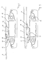
Figure 1 is a perspective view of a part of a vehicle having in its fixed roof an embodiment of the sunroof according to the invention. -
Figure 2 is a schematic plan view of the fixed roof of the vehicle ofFigure 1 . -
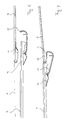
Figure 3 is an enlarged sectional view according to the line III-III inFigure 1 . -
Figures 4-6 are views corresponding to that ofFigure 3 but showing the sunroof panels in different positions. -
Figure 7 is a view corresponding to that ofFigure 3 , but showing a variation of this embodiment, and in a position with the rear closure member opened. -
Figures 8 and 9 are views corresponding to that ofFigure 3 but showing a second embodiment of the sunroof according to the invention in two different positions. -
Figures 1 and 2 partly show a vehicle, in this case a passenger car, which has in its fixed roof 1 one ormore openings 2 which can be selectively opened or closed by two or more closure members, in this case a first orfront closures member 3 and a second orrear closure member 4 which are part of a sunroof. In this case, theclosure members single opening 2 but it is also conceivable that each closure member is able to close its own roof opening. It is also possible that two closure members are arranged side by side in the fixed roof 1. - In
Figures 1 and 2 it is shown that bothclosure members solar cells 5 which are able to convert solar energy into electrical energy which should be supplied to an electrical consumer, either directly or through abattery 6.Figure 2 indicates schematically the vehicle'swire harness 7 and a point of contact 8 between therear closure member 4 and thewire harness 7. In this case therear closure member 4 is a pivotable panel and the continuous electrical contact betweenrear closure member 4 and a stationary part of the sunroof, for example in the form of a frame 9 (partly shown inFigures 8 and 9 ) is easily effected at the front of the closure member where no or hardly any displacement of therear closure member 4 takes place. -
Figures 3-6 show how the electrical connection takes place between the front closure member and the rear closure member in order to lead the energy from bothclosing members battery 6. -
Figures 3-6 show that the electrical connection between bothclosing members intermediate member 10, here in the form of a transverse drain channel which is positioned below the rear end of thefront closure member 3 and below the front end of therear closure member 4 in order to be able to catch and drain any water there. Thefront closure member 3 is of the so called vent-slider type, which means that thefront closure member 3 can be moved from its closed position within the roof opening 2 (Figure 3 ) on the one hand to an upwardly inclined venting position (Figure 4 ) and on the other hand to downwardly and rearwardly displaced open positions (Figures 5 and 6 ). Therear closure member 4 is movable from its closed position within the roof opening 2 (Figure 3 ) only to an upwardly inclined venting position (seeFigure 7 ). Therear closure member 4 is continuously connected electrically to thedrain channel 10 by means of a spring contact 11 (for example a spring strip) arranged at the underside of therear closure member 4, which is in contact with acontact area 12 of aconductor 13 provided on thedrain channel 10. This electrical contact allows a pivoting movement of therear closure member 4 while maintaining the electrical contact (seeFigure 7 ). - The
front closure member 3 is connected to theconductor 13 of thedrain channel 10 through a flexibleelectrical connection 14 which is for example formed by a coiled wire, a spring contact or other flexible member allowing a limited movement between thefront closure member 3 and thedrain channel 10. This movement is illustrated inFigures 3-5 , but also a limited sliding movement between thefront closure member 3 and thedrain channel 10 would be possible. -
Figures 5 and6 illustrate that if thefront closure member 3 is moved downwardly and rearwardly, thedrain channel 10 moves together with thefront closure member 3 and as a result thereof the contact between thedrain channel 10 and therear closure member 4 will be broken so that no electrical energy from thesolar cells 5 on thefront closure member 3 can be supplied to therear closure member 4 and thus to thebattery 6. This is however hardly any problem as thesolar cells 5 on thefront closure member 3 will catch less sunrays because they are hidden below therear closure member 4 and therefore deliver less electrical energy. -
Figure 7 illustrates a slight variation in the embodiment ofFigures 3-6 in that thespring contact 11 is now provided on thedrain channel 10 and cooperates with acontact area 12 at the underside of therear closure member 4. -
Figures 8 and 9 illustrate a further embodiment of the sunroof according to the invention. In this embodiment the intermediate member is stationary and is formed by ahousing 15 ofroller sunscreen 16. Thishousing 15 is provided below the rear end of thefront closure member 3 and the front end of therear closure member 4. Thehousing 15 carries on its upper side anelectrical conductor 17 having twospring contacts 18 enabling an electrical contact with contact areas on the front andrear closure members Figures 8 and 9 it is shown that thefront spring contact 18 can effect an electrical contact with arear contact area 20 as shown inFigure 8 and with afront contact area 21 on theclosure member 3 as shown inFigure 9 . An electrical connection is thus effected in different positions of thefront closure member 3 throughdifferent contact areas - From the foregoing description it follows that the invention provides a sunroof having two or more closure members which enable an effective electrical connection between the closing members and the stationary part of the sunroof.
- The invention is not limited to the embodiments shown in the drawings and described above and can be varied in different manners within the scope of the invention. For example, aspects of the different embodiments can be used in different combinations. It is possible that the closing members comprise an electrical consumer, such as a fan, instead of an energy source. The closure members can also have different configurations, such as folding members, rigid or flexible flaps and the like. Several roof openings may be present which are separated by roof sections or the like. More than two closure members may be provided, and also at least one of the closure members can be a fixed closure member, for example the rear closure member. Movable closure members may make other movements from the closed position, such as forward movements, folding movements and the like. Also the intermediate member may make other or additional movements such as a downward movement and pivoting movement. The intermediate member may also be provided in another position, for example at the side of the closure members or between closure members arranged side-by-side.
Claims (15)
- Sunroof for a vehicle having an opening (2) in its fixed roof (1), comprising:a stationary part (9) to be attached to the vehicle,at least a first closure member (3) and a second closure member (4), supported by the stationary part, at least one of the closure members being movable between a closed position within the roof opening and an open position in which it is moved at least partly away from the roof opening,an intermediate member (10; 15) supported by the stationary part, preferably in the area between the closure members when they are in their closed position,an electrical part (5) on each of the closure members requiring electrical connections (8, 11-14; 17-21) between each closure member and the stationary part,
wherein the electrical connection (11-14; 17-21) between the closure members (3, 4) is effected through the intermediate member (10; 15), while the connection to the stationary part (9) is effected through one of the intermediate member and closure members which has the least displacement with respect to the stationary part. - The sunroof of claim 1, wherein the second closure member (4) is a pivotable closure panel.
- The sunroof of claim 1 or 2, wherein the first closure member (3) is slidable.
- The sunroof of any one of the preceding claims, wherein at least a part of one (4) of the closure members (3, 4) is substantially stationary and is electrically connected to the stationary part (9), and wherein the other closure member (3) is disconnectably connected to the one closure member (4) through the intermediate member (10; 15).
- The sunroof of claim 4, wherein the second closure member (4) is connected to the stationary part (9).
- The sunroof of any of the preceding claims, wherein the electrical connection (14) between the first closure member (3) and the intermediate member (10) is flexible so as to allow movement therebetween.
- The sunroof of claim 6, wherein the first closure member (3) is a panel that is pivotable to a venting position.
- The sunroof of claim 6 or 7, wherein the flexible electrical connection (14) between the first closure member (3) and the intermediate member (10) comprises a coiled wire and/or a spring contact.
- The sunroof of any one of preceding claims, wherein the intermediate member (10; 15) and the second closure member (4) have a contact area (12; 19) on one and a spring contact (11; 18) on the other.
- The sunroof of any one of the preceding claims, wherein the intermediate member (10) is movable, e.g. slidable.
- The sunroof of any of the preceding claims, wherein the first and second closure members are front and rear closure members, and wherein the intermediate member (10) is a transverse drain channel at a position below the rear end of the front closure member (3) and the front end of the rear closure member (4) when they are in their closed position.
- The sunroof of claim 11, wherein the drain channel (10) is slidable together with the front closure member (3) to a position below the rear closure member (4), the front closure member and the drain channel being permanently electrically connected (14), while the electrical connection (11, 12) between the drain channel and the rear closure member is disconnectable.
- The sunroof of any one of claims 1 - 3, wherein the intermediate member (15) is stationary, and is for example formed by a housing of one or more roller screens (16) at a position below an end of the first closure member (3) and an end of the second closure member (4) when they are in their closed position.
- The sunroof of claims 3 and 13, wherein the first closure member (3) has at least two contact areas (20, 21) which enable an electrical connection between the first closure member and a contact point (18) on the intermediate member (15) in the closed position and at least one open position of the first closure member.
- The sunroof of any of the preceding claims, wherein the electrical part (5) comprises solar cells for connection to a battery (6) or an electrical consumer in the vehicle.
Priority Applications (1)
| Application Number | Priority Date | Filing Date | Title |
|---|---|---|---|
| EP11162221.3A EP2377705B1 (en) | 2010-04-14 | 2011-04-13 | Sunroof for a vehicle |
Applications Claiming Priority (2)
| Application Number | Priority Date | Filing Date | Title |
|---|---|---|---|
| EP10159883 | 2010-04-14 | ||
| EP11162221.3A EP2377705B1 (en) | 2010-04-14 | 2011-04-13 | Sunroof for a vehicle |
Publications (2)
| Publication Number | Publication Date |
|---|---|
| EP2377705A1 true EP2377705A1 (en) | 2011-10-19 |
| EP2377705B1 EP2377705B1 (en) | 2013-06-12 |
Family
ID=42173753
Family Applications (1)
| Application Number | Title | Priority Date | Filing Date |
|---|---|---|---|
| EP11162221.3A Active EP2377705B1 (en) | 2010-04-14 | 2011-04-13 | Sunroof for a vehicle |
Country Status (3)
| Country | Link |
|---|---|
| US (1) | US8348336B2 (en) |
| EP (1) | EP2377705B1 (en) |
| CN (1) | CN102218984B (en) |
Cited By (1)
| Publication number | Priority date | Publication date | Assignee | Title |
|---|---|---|---|---|
| WO2016083300A1 (en) * | 2014-11-24 | 2016-06-02 | Webasto SE | Vehicle roof |
Families Citing this family (14)
| Publication number | Priority date | Publication date | Assignee | Title |
|---|---|---|---|---|
| JP5790221B2 (en) * | 2011-07-12 | 2015-10-07 | アイシン精機株式会社 | Vehicle roof device |
| JP2013169845A (en) * | 2012-02-20 | 2013-09-02 | Yachiyo Industry Co Ltd | Power supply structure to electric device in roof panel device |
| JP2014040167A (en) * | 2012-08-22 | 2014-03-06 | Yachiyo Industry Co Ltd | Sunroof device |
| JP5631944B2 (en) * | 2012-08-22 | 2014-11-26 | 八千代工業株式会社 | Sunroof device |
| CN104553698A (en) * | 2013-10-14 | 2015-04-29 | 信昌机械厂股份有限公司 | Automobile skylight |
| KR101637717B1 (en) | 2014-11-04 | 2016-07-20 | 현대자동차주식회사 | Electric interconnection system for solar cell of vehicle roof |
| US9876467B2 (en) * | 2015-02-23 | 2018-01-23 | Hyundai Motor Company | Wiring structure for solar cell roof |
| KR101662549B1 (en) * | 2015-07-02 | 2016-10-06 | 현대자동차주식회사 | Power transmission apparatus of sunroof for vehicle |
| KR101820773B1 (en) * | 2016-10-06 | 2018-01-22 | 주식회사 지투비 | Structure of power connecting of sunroof for vehicle |
| CN215705609U (en) * | 2018-07-12 | 2022-02-01 | 金泰克斯公司 | Vehicle equipment |
| KR20200079915A (en) * | 2018-12-26 | 2020-07-06 | 현대자동차주식회사 | Solar cell module for vehicle panel and vehicle panel assembly including the same |
| EP3969303A4 (en) * | 2019-06-21 | 2022-06-29 | Gentex Corporation | Electrical connection method to movable window |
| KR20210022391A (en) | 2019-08-20 | 2021-03-03 | 현대자동차주식회사 | Photovoltaic panel mounting system for vehicle |
| DE102022126124A1 (en) * | 2022-10-10 | 2024-04-11 | Webasto SE | Glass pane device and motor vehicle |
Citations (4)
| Publication number | Priority date | Publication date | Assignee | Title |
|---|---|---|---|---|
| DE19813324A1 (en) * | 1998-03-26 | 1999-10-07 | Webasto Systemkomponenten Gmbh | Car sunroof with solar cells |
| DE19937221C1 (en) * | 1999-08-06 | 2000-09-07 | Webasto Dachsysteme Gmbh | Solar vehicle roof has additional element with additional solar generator for coupling to closure element in open position so additional element adopts working position on vehicle exterior |
| DE29824997U1 (en) * | 1998-10-29 | 2004-02-19 | Webasto Vehicle Systems International Gmbh | Automobile transparent sunroof has sliding and stationary sunroof sections with non-transparent area of one or both provided with solar cells |
| EP1442907A2 (en) * | 2003-01-29 | 2004-08-04 | Inalfa Roof Systems Group B.V. | Open roof construction for a vehicle and method of operating it |
Family Cites Families (12)
| Publication number | Priority date | Publication date | Assignee | Title |
|---|---|---|---|---|
| DE3730112A1 (en) * | 1987-09-08 | 1989-03-23 | Webasto Ag Fahrzeugtechnik | VEHICLE ROOF WITH FRONT AND REAR LID |
| US4934753A (en) | 1988-10-05 | 1990-06-19 | Ford Motor Company | Electrical connectors for use with a retractable sunroof containing elements that respond to an applied electrical signal |
| EP0436283A3 (en) | 1989-12-20 | 1991-11-27 | Asc Incorporated | Retracting sunroof system with variable opacity |
| US5261722A (en) * | 1989-12-20 | 1993-11-16 | Asc Incorporated | Variable opacity, maximally transverse retracting sunroof system |
| DE4020655C1 (en) | 1990-06-29 | 1991-05-02 | Webasto Ag Fahrzeugtechnik, 8035 Stockdorf, De | |
| DE19849840C1 (en) | 1998-10-29 | 2000-02-17 | Webasto Karosseriesysteme | Automobile transparent sunroof has sliding and stationary sunroof sections with non-transparent area of one or both provided with solar cells |
| DE19852383B4 (en) | 1998-11-13 | 2007-01-25 | Webasto Ag | Roof module for a vehicle and method of making the same |
| DE19937220C1 (en) * | 1999-08-06 | 2001-03-01 | Webasto Vehicle Sys Int Gmbh | Vehicle roof with adjustable locking element |
| DE202004001916U1 (en) * | 2004-02-09 | 2004-04-08 | Arvinmeritor Gmbh | Mechanism for a sunroof |
| EP1780066B1 (en) * | 2005-10-31 | 2009-12-09 | Inalfa Roof Systems Group B.V. | Open roof construction for a vehicle and wind deflector |
| CN2913064Y (en) * | 2005-12-16 | 2007-06-20 | 比亚迪股份有限公司 | Automobile connecting rod outer open electric sky-light |
| US7441833B1 (en) * | 2007-05-15 | 2008-10-28 | Webasto Roof Systems, Inc. | Arrangement and method for converting of single panel sunroofs into double panel sunroofs and component parts thereof |
-
2011
- 2011-04-08 CN CN201110087474.0A patent/CN102218984B/en active Active
- 2011-04-13 EP EP11162221.3A patent/EP2377705B1/en active Active
- 2011-04-14 US US13/086,983 patent/US8348336B2/en active Active
Patent Citations (4)
| Publication number | Priority date | Publication date | Assignee | Title |
|---|---|---|---|---|
| DE19813324A1 (en) * | 1998-03-26 | 1999-10-07 | Webasto Systemkomponenten Gmbh | Car sunroof with solar cells |
| DE29824997U1 (en) * | 1998-10-29 | 2004-02-19 | Webasto Vehicle Systems International Gmbh | Automobile transparent sunroof has sliding and stationary sunroof sections with non-transparent area of one or both provided with solar cells |
| DE19937221C1 (en) * | 1999-08-06 | 2000-09-07 | Webasto Dachsysteme Gmbh | Solar vehicle roof has additional element with additional solar generator for coupling to closure element in open position so additional element adopts working position on vehicle exterior |
| EP1442907A2 (en) * | 2003-01-29 | 2004-08-04 | Inalfa Roof Systems Group B.V. | Open roof construction for a vehicle and method of operating it |
Cited By (1)
| Publication number | Priority date | Publication date | Assignee | Title |
|---|---|---|---|---|
| WO2016083300A1 (en) * | 2014-11-24 | 2016-06-02 | Webasto SE | Vehicle roof |
Also Published As
| Publication number | Publication date |
|---|---|
| CN102218984A (en) | 2011-10-19 |
| US8348336B2 (en) | 2013-01-08 |
| US20110254324A1 (en) | 2011-10-20 |
| EP2377705B1 (en) | 2013-06-12 |
| CN102218984B (en) | 2015-04-01 |
Similar Documents
| Publication | Publication Date | Title |
|---|---|---|
| EP2377705B1 (en) | Sunroof for a vehicle | |
| CN101905641B (en) | Sunroof device | |
| US20130341972A1 (en) | Roller blind apparatus for panoramic sunroofs | |
| US8607505B2 (en) | Sealing assembly for a vehicle | |
| KR101240988B1 (en) | Panarama roof apparatus for vehicle | |
| CN102371878A (en) | Retracting seal surface enabling independent action of opposing hinged vehicle doors | |
| CN1118386C (en) | Vehicle roof with adjustable closing mechanism | |
| WO2016150353A1 (en) | Multi-purpose vehicle | |
| US9876467B2 (en) | Wiring structure for solar cell roof | |
| KR101466467B1 (en) | Opening and closing apparatus for sunroof | |
| EP1403112B1 (en) | Vehicle sunroof structure | |
| CN205417120U (en) | Skylight drainage device | |
| US9573449B2 (en) | Power transmission apparatus for vehicle sunroof | |
| EP2848470B1 (en) | Sunshade assembly comprising electric switching means | |
| EP2105333B1 (en) | Roof assembly for a vehicle and method of operating same | |
| US20110120020A1 (en) | Device for closing off a window made in a motor vehicle, corresponding roof and corresponding vehicle | |
| CN108312817B (en) | Structure of electric sunshade and skylight | |
| KR101816420B1 (en) | Power connecting system of roof panel having solar cell | |
| JP2011111143A (en) | Power feeding device for glass | |
| EP1612074A1 (en) | Sunshade Device for Vehicle | |
| EP1614572A3 (en) | Roof assembly for vehicle for opening and closing of a roof opening and a vehicle equipped with it | |
| CN209650011U (en) | Band garage switch lever formula sunshading board | |
| JP4207594B2 (en) | Vehicle roof trim | |
| JP3508145B2 (en) | Slide roof structure | |
| CN208602293U (en) | Sunshading board |
Legal Events
| Date | Code | Title | Description |
|---|---|---|---|
| AK | Designated contracting states |
Kind code of ref document: A1 Designated state(s): AL AT BE BG CH CY CZ DE DK EE ES FI FR GB GR HR HU IE IS IT LI LT LU LV MC MK MT NL NO PL PT RO RS SE SI SK SM TR |
|
| AX | Request for extension of the european patent |
Extension state: BA ME |
|
| PUAI | Public reference made under article 153(3) epc to a published international application that has entered the european phase |
Free format text: ORIGINAL CODE: 0009012 |
|
| 17P | Request for examination filed |
Effective date: 20120411 |
|
| REG | Reference to a national code |
Ref country code: DE Ref legal event code: R079 Ref document number: 602011001980 Country of ref document: DE Free format text: PREVIOUS MAIN CLASS: B60J0007050000 Ipc: B60J0007000000 |
|
| GRAP | Despatch of communication of intention to grant a patent |
Free format text: ORIGINAL CODE: EPIDOSNIGR1 |
|
| RIC1 | Information provided on ipc code assigned before grant |
Ipc: B60J 7/05 20060101ALI20121214BHEP Ipc: B60J 7/00 20060101AFI20121214BHEP |
|
| RIN1 | Information on inventor provided before grant (corrected) |
Inventor name: DE BIE, SANDER |
|
| GRAS | Grant fee paid |
Free format text: ORIGINAL CODE: EPIDOSNIGR3 |
|
| GRAA | (expected) grant |
Free format text: ORIGINAL CODE: 0009210 |
|
| AK | Designated contracting states |
Kind code of ref document: B1 Designated state(s): AL AT BE BG CH CY CZ DE DK EE ES FI FR GB GR HR HU IE IS IT LI LT LU LV MC MK MT NL NO PL PT RO RS SE SI SK SM TR |
|
| REG | Reference to a national code |
Ref country code: GB Ref legal event code: FG4D |
|
| REG | Reference to a national code |
Ref country code: CH Ref legal event code: EP |
|
| REG | Reference to a national code |
Ref country code: AT Ref legal event code: REF Ref document number: 616543 Country of ref document: AT Kind code of ref document: T Effective date: 20130615 |
|
| REG | Reference to a national code |
Ref country code: IE Ref legal event code: FG4D |
|
| REG | Reference to a national code |
Ref country code: DE Ref legal event code: R096 Ref document number: 602011001980 Country of ref document: DE Effective date: 20130808 |
|
| PG25 | Lapsed in a contracting state [announced via postgrant information from national office to epo] |
Ref country code: FI Free format text: LAPSE BECAUSE OF FAILURE TO SUBMIT A TRANSLATION OF THE DESCRIPTION OR TO PAY THE FEE WITHIN THE PRESCRIBED TIME-LIMIT Effective date: 20130612 Ref country code: GR Free format text: LAPSE BECAUSE OF FAILURE TO SUBMIT A TRANSLATION OF THE DESCRIPTION OR TO PAY THE FEE WITHIN THE PRESCRIBED TIME-LIMIT Effective date: 20130913 Ref country code: LT Free format text: LAPSE BECAUSE OF FAILURE TO SUBMIT A TRANSLATION OF THE DESCRIPTION OR TO PAY THE FEE WITHIN THE PRESCRIBED TIME-LIMIT Effective date: 20130612 Ref country code: SI Free format text: LAPSE BECAUSE OF FAILURE TO SUBMIT A TRANSLATION OF THE DESCRIPTION OR TO PAY THE FEE WITHIN THE PRESCRIBED TIME-LIMIT Effective date: 20130612 Ref country code: ES Free format text: LAPSE BECAUSE OF FAILURE TO SUBMIT A TRANSLATION OF THE DESCRIPTION OR TO PAY THE FEE WITHIN THE PRESCRIBED TIME-LIMIT Effective date: 20130923 Ref country code: SE Free format text: LAPSE BECAUSE OF FAILURE TO SUBMIT A TRANSLATION OF THE DESCRIPTION OR TO PAY THE FEE WITHIN THE PRESCRIBED TIME-LIMIT Effective date: 20130612 Ref country code: NO Free format text: LAPSE BECAUSE OF FAILURE TO SUBMIT A TRANSLATION OF THE DESCRIPTION OR TO PAY THE FEE WITHIN THE PRESCRIBED TIME-LIMIT Effective date: 20130912 |
|
| REG | Reference to a national code |
Ref country code: AT Ref legal event code: MK05 Ref document number: 616543 Country of ref document: AT Kind code of ref document: T Effective date: 20130612 |
|
| REG | Reference to a national code |
Ref country code: NL Ref legal event code: VDEP Effective date: 20130612 |
|
| REG | Reference to a national code |
Ref country code: LT Ref legal event code: MG4D |
|
| PG25 | Lapsed in a contracting state [announced via postgrant information from national office to epo] |
Ref country code: BG Free format text: LAPSE BECAUSE OF FAILURE TO SUBMIT A TRANSLATION OF THE DESCRIPTION OR TO PAY THE FEE WITHIN THE PRESCRIBED TIME-LIMIT Effective date: 20130912 Ref country code: HR Free format text: LAPSE BECAUSE OF FAILURE TO SUBMIT A TRANSLATION OF THE DESCRIPTION OR TO PAY THE FEE WITHIN THE PRESCRIBED TIME-LIMIT Effective date: 20130612 Ref country code: RS Free format text: LAPSE BECAUSE OF FAILURE TO SUBMIT A TRANSLATION OF THE DESCRIPTION OR TO PAY THE FEE WITHIN THE PRESCRIBED TIME-LIMIT Effective date: 20130612 |
|
| PG25 | Lapsed in a contracting state [announced via postgrant information from national office to epo] |
Ref country code: LV Free format text: LAPSE BECAUSE OF FAILURE TO SUBMIT A TRANSLATION OF THE DESCRIPTION OR TO PAY THE FEE WITHIN THE PRESCRIBED TIME-LIMIT Effective date: 20130612 |
|
| PG25 | Lapsed in a contracting state [announced via postgrant information from national office to epo] |
Ref country code: AT Free format text: LAPSE BECAUSE OF FAILURE TO SUBMIT A TRANSLATION OF THE DESCRIPTION OR TO PAY THE FEE WITHIN THE PRESCRIBED TIME-LIMIT Effective date: 20130612 Ref country code: CZ Free format text: LAPSE BECAUSE OF FAILURE TO SUBMIT A TRANSLATION OF THE DESCRIPTION OR TO PAY THE FEE WITHIN THE PRESCRIBED TIME-LIMIT Effective date: 20130612 Ref country code: PT Free format text: LAPSE BECAUSE OF FAILURE TO SUBMIT A TRANSLATION OF THE DESCRIPTION OR TO PAY THE FEE WITHIN THE PRESCRIBED TIME-LIMIT Effective date: 20131014 Ref country code: EE Free format text: LAPSE BECAUSE OF FAILURE TO SUBMIT A TRANSLATION OF THE DESCRIPTION OR TO PAY THE FEE WITHIN THE PRESCRIBED TIME-LIMIT Effective date: 20130612 Ref country code: BE Free format text: LAPSE BECAUSE OF FAILURE TO SUBMIT A TRANSLATION OF THE DESCRIPTION OR TO PAY THE FEE WITHIN THE PRESCRIBED TIME-LIMIT Effective date: 20130612 Ref country code: SK Free format text: LAPSE BECAUSE OF FAILURE TO SUBMIT A TRANSLATION OF THE DESCRIPTION OR TO PAY THE FEE WITHIN THE PRESCRIBED TIME-LIMIT Effective date: 20130612 Ref country code: IS Free format text: LAPSE BECAUSE OF FAILURE TO SUBMIT A TRANSLATION OF THE DESCRIPTION OR TO PAY THE FEE WITHIN THE PRESCRIBED TIME-LIMIT Effective date: 20131012 |
|
| PG25 | Lapsed in a contracting state [announced via postgrant information from national office to epo] |
Ref country code: NL Free format text: LAPSE BECAUSE OF FAILURE TO SUBMIT A TRANSLATION OF THE DESCRIPTION OR TO PAY THE FEE WITHIN THE PRESCRIBED TIME-LIMIT Effective date: 20130612 Ref country code: RO Free format text: LAPSE BECAUSE OF FAILURE TO SUBMIT A TRANSLATION OF THE DESCRIPTION OR TO PAY THE FEE WITHIN THE PRESCRIBED TIME-LIMIT Effective date: 20130612 Ref country code: PL Free format text: LAPSE BECAUSE OF FAILURE TO SUBMIT A TRANSLATION OF THE DESCRIPTION OR TO PAY THE FEE WITHIN THE PRESCRIBED TIME-LIMIT Effective date: 20130612 |
|
| PLBE | No opposition filed within time limit |
Free format text: ORIGINAL CODE: 0009261 |
|
| STAA | Information on the status of an ep patent application or granted ep patent |
Free format text: STATUS: NO OPPOSITION FILED WITHIN TIME LIMIT |
|
| PG25 | Lapsed in a contracting state [announced via postgrant information from national office to epo] |
Ref country code: DK Free format text: LAPSE BECAUSE OF FAILURE TO SUBMIT A TRANSLATION OF THE DESCRIPTION OR TO PAY THE FEE WITHIN THE PRESCRIBED TIME-LIMIT Effective date: 20130612 |
|
| 26N | No opposition filed |
Effective date: 20140313 |
|
| PG25 | Lapsed in a contracting state [announced via postgrant information from national office to epo] |
Ref country code: IT Free format text: LAPSE BECAUSE OF FAILURE TO SUBMIT A TRANSLATION OF THE DESCRIPTION OR TO PAY THE FEE WITHIN THE PRESCRIBED TIME-LIMIT Effective date: 20130612 |
|
| REG | Reference to a national code |
Ref country code: DE Ref legal event code: R097 Ref document number: 602011001980 Country of ref document: DE Effective date: 20140313 |
|
| PG25 | Lapsed in a contracting state [announced via postgrant information from national office to epo] |
Ref country code: MC Free format text: LAPSE BECAUSE OF FAILURE TO SUBMIT A TRANSLATION OF THE DESCRIPTION OR TO PAY THE FEE WITHIN THE PRESCRIBED TIME-LIMIT Effective date: 20130612 Ref country code: LU Free format text: LAPSE BECAUSE OF FAILURE TO SUBMIT A TRANSLATION OF THE DESCRIPTION OR TO PAY THE FEE WITHIN THE PRESCRIBED TIME-LIMIT Effective date: 20140413 |
|
| REG | Reference to a national code |
Ref country code: CH Ref legal event code: PL |
|
| REG | Reference to a national code |
Ref country code: IE Ref legal event code: MM4A |
|
| PG25 | Lapsed in a contracting state [announced via postgrant information from national office to epo] |
Ref country code: LI Free format text: LAPSE BECAUSE OF NON-PAYMENT OF DUE FEES Effective date: 20140430 Ref country code: CH Free format text: LAPSE BECAUSE OF NON-PAYMENT OF DUE FEES Effective date: 20140430 |
|
| PG25 | Lapsed in a contracting state [announced via postgrant information from national office to epo] |
Ref country code: IE Free format text: LAPSE BECAUSE OF NON-PAYMENT OF DUE FEES Effective date: 20140413 |
|
| PG25 | Lapsed in a contracting state [announced via postgrant information from national office to epo] |
Ref country code: MT Free format text: LAPSE BECAUSE OF FAILURE TO SUBMIT A TRANSLATION OF THE DESCRIPTION OR TO PAY THE FEE WITHIN THE PRESCRIBED TIME-LIMIT Effective date: 20130612 |
|
| REG | Reference to a national code |
Ref country code: FR Ref legal event code: PLFP Year of fee payment: 6 |
|
| PG25 | Lapsed in a contracting state [announced via postgrant information from national office to epo] |
Ref country code: SM Free format text: LAPSE BECAUSE OF FAILURE TO SUBMIT A TRANSLATION OF THE DESCRIPTION OR TO PAY THE FEE WITHIN THE PRESCRIBED TIME-LIMIT Effective date: 20130612 |
|
| PG25 | Lapsed in a contracting state [announced via postgrant information from national office to epo] |
Ref country code: CY Free format text: LAPSE BECAUSE OF FAILURE TO SUBMIT A TRANSLATION OF THE DESCRIPTION OR TO PAY THE FEE WITHIN THE PRESCRIBED TIME-LIMIT Effective date: 20130612 |
|
| PG25 | Lapsed in a contracting state [announced via postgrant information from national office to epo] |
Ref country code: HU Free format text: LAPSE BECAUSE OF FAILURE TO SUBMIT A TRANSLATION OF THE DESCRIPTION OR TO PAY THE FEE WITHIN THE PRESCRIBED TIME-LIMIT; INVALID AB INITIO Effective date: 20110413 Ref country code: TR Free format text: LAPSE BECAUSE OF FAILURE TO SUBMIT A TRANSLATION OF THE DESCRIPTION OR TO PAY THE FEE WITHIN THE PRESCRIBED TIME-LIMIT Effective date: 20130612 |
|
| PGFP | Annual fee paid to national office [announced via postgrant information from national office to epo] |
Ref country code: GB Payment date: 20160427 Year of fee payment: 6 |
|
| REG | Reference to a national code |
Ref country code: FR Ref legal event code: PLFP Year of fee payment: 7 |
|
| GBPC | Gb: european patent ceased through non-payment of renewal fee |
Effective date: 20170413 |
|
| PG25 | Lapsed in a contracting state [announced via postgrant information from national office to epo] |
Ref country code: GB Free format text: LAPSE BECAUSE OF NON-PAYMENT OF DUE FEES Effective date: 20170413 |
|
| REG | Reference to a national code |
Ref country code: FR Ref legal event code: PLFP Year of fee payment: 8 |
|
| PG25 | Lapsed in a contracting state [announced via postgrant information from national office to epo] |
Ref country code: MK Free format text: LAPSE BECAUSE OF FAILURE TO SUBMIT A TRANSLATION OF THE DESCRIPTION OR TO PAY THE FEE WITHIN THE PRESCRIBED TIME-LIMIT Effective date: 20130612 |
|
| PG25 | Lapsed in a contracting state [announced via postgrant information from national office to epo] |
Ref country code: AL Free format text: LAPSE BECAUSE OF FAILURE TO SUBMIT A TRANSLATION OF THE DESCRIPTION OR TO PAY THE FEE WITHIN THE PRESCRIBED TIME-LIMIT Effective date: 20130612 |
|
| PGFP | Annual fee paid to national office [announced via postgrant information from national office to epo] |
Ref country code: FR Payment date: 20230425 Year of fee payment: 13 Ref country code: DE Payment date: 20230427 Year of fee payment: 13 |