EP2377671A1 - Apparatus for producing three-dimensional shaped product - Google Patents
Apparatus for producing three-dimensional shaped product Download PDFInfo
- Publication number
- EP2377671A1 EP2377671A1 EP10167810A EP10167810A EP2377671A1 EP 2377671 A1 EP2377671 A1 EP 2377671A1 EP 10167810 A EP10167810 A EP 10167810A EP 10167810 A EP10167810 A EP 10167810A EP 2377671 A1 EP2377671 A1 EP 2377671A1
- Authority
- EP
- European Patent Office
- Prior art keywords
- base plate
- supports
- projected
- powder
- recesses
- Prior art date
- Legal status (The legal status is an assumption and is not a legal conclusion. Google has not performed a legal analysis and makes no representation as to the accuracy of the status listed.)
- Granted
Links
Images


Classifications
-
- B—PERFORMING OPERATIONS; TRANSPORTING
- B29—WORKING OF PLASTICS; WORKING OF SUBSTANCES IN A PLASTIC STATE IN GENERAL
- B29C—SHAPING OR JOINING OF PLASTICS; SHAPING OF MATERIAL IN A PLASTIC STATE, NOT OTHERWISE PROVIDED FOR; AFTER-TREATMENT OF THE SHAPED PRODUCTS, e.g. REPAIRING
- B29C64/00—Additive manufacturing, i.e. manufacturing of three-dimensional [3D] objects by additive deposition, additive agglomeration or additive layering, e.g. by 3D printing, stereolithography or selective laser sintering
- B29C64/40—Structures for supporting 3D objects during manufacture and intended to be sacrificed after completion thereof
-
- B—PERFORMING OPERATIONS; TRANSPORTING
- B29—WORKING OF PLASTICS; WORKING OF SUBSTANCES IN A PLASTIC STATE IN GENERAL
- B29C—SHAPING OR JOINING OF PLASTICS; SHAPING OF MATERIAL IN A PLASTIC STATE, NOT OTHERWISE PROVIDED FOR; AFTER-TREATMENT OF THE SHAPED PRODUCTS, e.g. REPAIRING
- B29C64/00—Additive manufacturing, i.e. manufacturing of three-dimensional [3D] objects by additive deposition, additive agglomeration or additive layering, e.g. by 3D printing, stereolithography or selective laser sintering
- B29C64/10—Processes of additive manufacturing
- B29C64/141—Processes of additive manufacturing using only solid materials
- B29C64/153—Processes of additive manufacturing using only solid materials using layers of powder being selectively joined, e.g. by selective laser sintering or melting
-
- B—PERFORMING OPERATIONS; TRANSPORTING
- B29—WORKING OF PLASTICS; WORKING OF SUBSTANCES IN A PLASTIC STATE IN GENERAL
- B29C—SHAPING OR JOINING OF PLASTICS; SHAPING OF MATERIAL IN A PLASTIC STATE, NOT OTHERWISE PROVIDED FOR; AFTER-TREATMENT OF THE SHAPED PRODUCTS, e.g. REPAIRING
- B29C64/00—Additive manufacturing, i.e. manufacturing of three-dimensional [3D] objects by additive deposition, additive agglomeration or additive layering, e.g. by 3D printing, stereolithography or selective laser sintering
- B29C64/10—Processes of additive manufacturing
- B29C64/188—Processes of additive manufacturing involving additional operations performed on the added layers, e.g. smoothing, grinding or thickness control
-
- B—PERFORMING OPERATIONS; TRANSPORTING
- B33—ADDITIVE MANUFACTURING TECHNOLOGY
- B33Y—ADDITIVE MANUFACTURING, i.e. MANUFACTURING OF THREE-DIMENSIONAL [3-D] OBJECTS BY ADDITIVE DEPOSITION, ADDITIVE AGGLOMERATION OR ADDITIVE LAYERING, e.g. BY 3-D PRINTING, STEREOLITHOGRAPHY OR SELECTIVE LASER SINTERING
- B33Y30/00—Apparatus for additive manufacturing; Details thereof or accessories therefor
Definitions
- the present invention relates to an apparatus for producing a three-dimensional shaped product in which metal powder or non-metal powder loaded on a vertically movable table is laminated while being sintered by irradiating electromagnetic waves to each layer, thereby producing a predetermined three-dimensional shaped product.
- step (c) is completed for a specific powder layer
- the powder on or around an object to be shaped is decreased in height only by one layer and the step (a) is resumed on a next powder layer.
- Patent Document 1 has adopted a configuration in which when powder is solidified by sintering ordinarily on the surface of a table (which is expressed as "support means 2" in Patent Document 1), a base plate is installed which is made by selecting a material adherable to the powder.
- an existing shaped part is influenced by the movement of a planarization apparatus in the step (a). Therefore, in order for the shaped part to be prevented from moving in a direction in which the apparatus moves, it is necessary that the base plate is kept stable on the surface of the table.
- Patent Document 1 Japanese Patent No. 4054075
- An object of the present invention is to provide an apparatus for producing a three-dimensional shaped product in which a base plate is interposed between a portion which is a region to be sintered among individual powder layers and a table, and a constitution of the apparatus for producing a three-dimensional shaped product in which the base plate is installed so as to form a vertical space between the table and itself, thereby eliminating a necessity for inserting a bolt from the table into the surface of the base plate.
- the present invention provides the following basic configurations:
- Both the basic configurations (1) and (2) have such a requirement that a base plate 3 can be supported by arrangement so that the center of gravity of the base plate 3 is present inside a triangle formed by three locations or a quadrangle formed by four locations inside a region where a support 4 and/or a projected streak 8 on which the base plate is supported.
- Powder 12 and a shaped article 13 loaded on the base plate 3 are equal in weight per unit area.
- M A M / a 1 / b 1 + a 2 / c 2 + 1
- M B M / b 1 / a 1 + b 3 / c 3 + 1
- M c M / c 2 / a 2 + c 3 / b 3 + 1 .
- any one of M A , M B and M C having a weight at the respective points of A, B and C is a positive value and not a negative value.
- the base plate 3 is supported stably without being accompanied by rotational moment.
- the support 4 and/or the step portion are in reality continued. Since three locations of A, B and C are not supported in an isolated manner, it is as a matter of course possible to support the base plate 3 stably where the center of gravity (G) of the base plate 3 is present inside the triangle ABC formed by the three locations (A, B, C).
- the drag forces M A , M B , M C and M D are common in that they correspond to the respective locations of A, B, C, and D and the weights equal to the surrounding unit areas thereof.
- it is impossible to keep the above fundamental formula that the sum of drag forces M A , M B , M C , and M D is equal to the whole weight M.
- the center of gravity (G) of the base plate 3 is not present inside any one of the triangles formed by the three locations. And, in such an arrangement that the center of gravity (G) is present inside a quadrangle formed by four locations, it is consequently possible to support the base plate 3 stably.
- the requirement is that in which in the apparatus for producing a three-dimensional shaped product, the longitudinal direction of the base plate 3 is crossed at least two supports 4 and/or projected streaks 8 and recesses 30 at the back of the base plate 3 are fitted into these supports 4 and/or projected streaks 8.
- the base plate 3 cannot move in the longitudinal direction but cannot move in other directions.
- the base plate 3 is unable to move in directions at which it is crossed to two supports 4 and/or projected streaks 8 in a crossed state as described above (for example, the directions indicated by the white arrows in Fig. 14 ), and finally the base plate 3 is completely prevented from moving in a two-dimensional planar direction by being fitted into two supports 4 and/or projected streaks 8.
- Fig. 5 (a) corresponds to an embodiment in which two supports 4 and/or projected streaks 8 are arranged so as to form an angle of 90 degrees with each other and recesses are fitted into two supports 4 and/or projected streaks 8 at the back of the circular base plate 3.
- Fig. 5 (a) shows in particular a case where two recesses 30 are fitted into one support 4 and one projected streak 8.
- Fig. 5 (b) corresponds to an embodiment in which three supports 4 and/or projected streaks 8 are arranged so as to form an angle of 120 degrees with each other in a mutually adjacent longitudinal direction and three recesses 30 at the back of the circular base plate 3 are fitted into the three supports 4 and/or projected streaks 8.
- Fig. 5 (b) shows in particular a case where the recesses 30 are fitted into only the supports 4.
- the base plate in a region where the base plate 3 is supported by the supports 4 and projected streaks 8 via fitting to the recesses 30, the base plate can be, as a matter of course, supported by arranging the center of gravity of the base plate 3 so as to be present in a triangle ABC formed by three locations A, B, C and can be supported stably in the vertical direction.
- the base plate 3 is completely prevented from moving horizontally since it fitted into the supports 4 and/or projected streaks 8. Still further, in production steps of (a), (b) and (c) described in the Description of the Related Art, the recesses 30 at the back of the base plate 3 are simply fitted into the supports 4 and the projected streaks 8 (as shown in Fig. 5 (a) ) and fitted into the supports 4 (as shown in Fig. 5 (b) ), thus making it possible to support the base plate 3 stably.
- These embodiments are quite simple in operation because a necessity is eliminated for fixation with screws as described in Patent Document 1.
- Figs. 6 correspond to an embodiment in which three to four supports 4 and/or projected streaks 8 are arranged so as to form an angle of 90 degrees with each other in an adjacent longitudinal direction and three or four recesses 30 at the back of the rectangular base plate 3 are fitted into these supports 4 and/or recesses 30.
- Fig. 6 (a) shows in particular a case where the recesses 30 are fitted into a total of four supports 4 in which two sets of two supports 4 are opposed to each other and two supports of them are connected to each other.
- Fig. 6 (b) shows in particular a case where the recesses are fitted into two supports 4 which are opposed to each other and one projected streak 8.
- the base plate 3 can be supported by arrangement so that the center of gravity (G) of the base plate 3 is present inside a quadrangle ABCD formed by four locations A, B, C, and D where the base plate 3 is supported with respect to the recess 30, thereby it is possible to support the base plate 3 stably in the vertical direction.
- the rectangular base plate 3 can be supported stably by the above-described arrangement exactly in the same way. Therefore, the explanation for this matter is omitted.
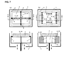
- Figs. 7 correspond to an embodiment in which, similar to Fig. 6 , three or four supports 4 and/or projected streaks 8 are arranged so as to form an angle of 90 degrees with each other in an adjacent longitudinal direction, and three or four recesses 30 at the back of the rectangular base plate 3 are fitted into the supports 4 and/or recesses 30 and in particular corresponds to an embodiment where the recessed parts are all fitted into the projected streaks 8.
- Figs. 7 (a) show in particular a case where the frame bodies 7 which are orthogonal to each other on the table 2 form a cross shape and the recesses 30 are fitted into the projected streaks 8 which are similarly crossed.
- Fig 7 (b) shows in particular a case where the recesses 30 are fitted into the projected streaks 8 arranged so as to be located at four rectangular sides respectively at the tops of four projected frames in a state of forming similar rectangular sides in the vicinity of the horizontally surrounding parts of the base plate 3.
- the base plate 3 can be stably supported not by using the support 4 in particular but using only the projected streaks 8 at the top of the frame body 7.
- Figs. 8 correspond to an embodiment in which two groups of two or more supports 4 which are opposed and also connected to each other are provided, a support 4 of one support group and that of the other support group are arranged so as to cross with each other at an angle of 90 degrees in the longitudinal direction, and recesses 30 arranged similarly at the back of the rectangular base plate 3 are fitted into these two groups of supports 4 arranged as described above.
- Fig. 8 shows in particular a case where one group made up of three supports 4 is orthogonal to the other group made up of two supports 4.
- the base plate 3 often takes on a rectangular shape or in particular a square shape.
- the recesses 30 are fitted into the supports 4 and/or projected streaks 8 in parallel and also orthogonal to each other. Thereby, the base plate 3 can be supported very firmly in preventing horizontal movement.
- the base plate 3 is prevented from moving horizontally in the basic configuration (2).
- the requirement is that in which a horizontally surrounding part of the base plate 3 is contacted with a projected part 5 provided at the support 4 on both sides in the longitudinal direction of at least one recess 30 among two recesses 30 and also projecting at least upward and/or a wall part of the projected frame.
- the base plate 3 can be prevented by these requirements from moving in a direction orthogonal to the recess 30 as shown in Fig. 15 .
- the base plate 3 is also prevented from moving horizontally along the longitudinal direction of the recess 30 on both sides in the longitudinal direction by the projected part 5 in contact with the horizontally surrounding part of the base plate 3 and/or the wall part.
- the projected part 5 is required to be provided at least on the support 4 and also projected upward. This is because the projected part 5 is required to be contacted with a horizontal outer surrounding part of the base plate 3 placed on the support 4.
- such an embodiment is also adoptable as the above-described projected part 5 that projects in the whole circumferential direction in the longitudinal direction of the support 4 like a nut and a collar part.
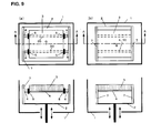
- Figs. 9 correspond to an embodiment in which, among four supports 4, two mutually-adjacent supports 4 are arranged to be in parallel to each other, two non-adjacent supports 4 are arranged to be opposed to each other, four recesses 30 at the back of the rectangular base plate 3 are fitted respectively into these supports 4, and the projected parts 5 provided on all the supports 4 or some of them and/or wall parts of the projected frame are contacted with two sides on both sides located at the horizontally surrounding parts of the base plate 3 orthogonal to the longitudinal direction of the supports 4.
- Fig. 9 (a) shows in particular a case where both sides of the recesses 30 are contacted with the projected parts 5
- Fig. 9 (b) shows in particular a case where both sides of the recesses 30 are contacted with the wall parts.
- the base plate 3 is inserted into the projected parts 5 or the wall parts on both sides and also the recesses 30 at the back of the base plate are fitted into the supports 4. Thereby, the base plate 3 is prevented from moving horizontally and can be supported stably.
- Figs. 10 corresponds to an embodiment in which two supports 4 are arranged so as to be opposed to each other, one projected streak 8 is arranged so as to be in parallel with these two supports 4, two recesses 30 at the back of the rectangular base plate 3 are fitted into the supports 4 and the projected streak 8, and the projected parts 5 provided on individual supports 4 and/or mutually-opposing wall parts of the projected frame at which the individual supports 4 are installed in a projecting manner are contacted with two sides on both sides located at the horizontally surrounding parts of the base plate 3 orthogonal to the longitudinal direction of the supports 4.
- Fig. 10 (a) shows in particular a case where the base plate 3 is contacted with projected parts 5 on both sides in the longitudinal direction on the recesses 30 and
- Fig. 10 (b) shows in particular a case where the base plate 3 is contacted with the wall parts on both sides in the longitudinal direction of the recesses 30.
- the base plate 3 is inserted into the projected parts 5 or the wall parts on both sides and two projected streaks 8 are fitted into the supports 4 and the projected streak 8. Thereby, the base plate 3 is prevented from moving horizontally and can be supported stably.
- Figs. 11 correspond to an embodiment in which two projected streaks 8 are provided in parallel on two frame bodies 7 which are opposed to each other, two recesses 30 installed at the back of the rectangular base plate 3 are fitted into these two projected streaks 8, and wall parts of other two mutually-opposing frame bodies 7 are contacted with two sides on both sides located at the horizontally surrounding parts of the base plate 3 orthogonal to the two projected streaks 8.
- Figs. 11 also show its specific mode.
- the support 4 is not provided in particular but the base plate 3 is simply inserted between the wall parts and recesses 30 are also fitted into the projected streaks 8 on both sides. Thereby, it is possible to support the base plate 3 stably.
- the base plate 3 is supported by the projected streaks 8 on both sides. Therefore, it is not necessary to provide the projected parts 5 on the support 4.
- both-side leg parts are installed in a projecting manner at the lower end of the frame body 7 in a direction in which the support 4 is installed in a projecting manner and also on the opposite side thereof, an insertion hole 20 is made on each of the both-side leg parts, a plurality of insertion holes 20 are made also on the table 2 depending on the direction in which each support 4 is installed in an projecting manner, stopping rods or stopping bolts are inserted through both insertion holes 20 for fixing individual support bodies 7 which are adjusted and selected by selecting the thus inserted locations, thereby making it possible to respond to base plates 3 in various shapes and dimensions and to adjust the location of the base plate 3 in the horizontal direction.
- Powder 12 adoptable in the present invention includes metal powder, ceramic powder, resin-coated metal powder or ceramic powder or resin-coated sand.
- the base plate 3 used in the basic configurations (1) and (2) is that in which the powder 12 is initially sprayed on the surface of the base plate 3 in the previously described step (a) and, the powder 12 must be adhered upon solidification of the powder 12 by sintering in the previously described step (b).
- any material may be selected as long as it can be adhered.
- the same material as the previously described exemplified powder 12 is often adopted.
- the base plate 3 consequently configures the lowest end of a three-dimensional shaped product.
- a heating plate (heater) or a cooling plate (cooler) is interposed between the table 2 and the base plate 3.
- the heating plate (heater) or the cooling plate (cooler) is interposed between the support 4 of the base plate 3 and/or the step site (not illustrated).
- One of the heating plate and the cooling plate may be selected depending on shaping conditions.
- Example 1 is characterized in that, as shown in Fig. 1 , a powder supporting plate 9 is installed between a region into which the recessed part of the base plate 3 is not fitted and the top of the frame body 7 with which the horizontally surrounding part is not in contact among supports 4.
- the powder supporting plate 9 is removed from the state shown in Fig. 1 (a) .
- the powder 12 is loaded inside a space formed by the table 2 and the frame body 7, and the table 2 is then moved above, thus making it possible to discharge the powder 12 outside a container.
- Example 2 is characterized in that, as shown in Fig. 2 , on the table 2, an inclined state sequentially lowering at a whole region inside a location supporting the frame body 7 or at a region further inside away from the location is formed, and a discharge opening 21 is provided at the lower end in the inclined table for discharging the powder 12 which has not been sintered.
- Example 1 As a matter of course, the powder 12 remaining on the powder supporting plate 9 is not subjected to sintering and shaping.
- Example 2 the remaining powder 12 lowers along the lower part of the inclined table and can be discharged through an opening located at the lowest part into the lower part of a shaping tank 1. Then, it is possible to reuse the powder 12.
- a region in which the above inclined state is provided may include not only a whole region inside a location at which the frame body 7 is installed upright but also a whole region further inside away from the location. This is because in the embodiments shown in Fig. 7 (b) and Figs. 11 , where a location for fixing the frame body 7 can be selected depending on the direction in which the support 4 comes into contact as shown in Figs. 13 , it is necessary that the table 2 is in a planar shape from a location where the frame body 7 is installed in a projecting manner to a predetermined inside region.
- Example 3 is characterized in that, on the table 2, an inclined state sequentially lowering from one end to the other end which are opposed to each other at a whole region inside a location for supporting the frame body 7 or at a region further inside away from the location, the frame body 7 is supported via two perpendicular supports 11 at the other end, and between the two perpendicular supports 11, provided is an opening/closing plate 10 capable of rotationally moving either the upper end position sandwiched by the two perpendicular supports 11 or these two perpendicular supports 11.
- Example 3 Similar to Example 2, also in Example 3, the powder 12 which has not been sintered or shaped is allowed to fall on the table 2 and the opening/closing plate 10 located between the perpendicular supports 11 is opened, thus making it possible to discharge the powder 12 from the surface of the table 2 to the outside. Then, Similar to Example 2, it is possible to discharge the powder 12 to the outside effectively and reuse the powder 12.
- Fig. 3 shows a state that the opening/closing plate 10 moving rotationally is kept opened at the upper ends of two perpendicular supports 11 but at a stage where shaping is performed, as a matter of course, the opening/closing plate 10 is located between the perpendicular supports 11 and kept closed.
- a region having the inclined state includes a whole region further inside away from a location where the frame body 7 is installed upright.
- the grounds thereof are the same as that described in Example 2.
- Example 4 is characterized in that, a molded layer made of powder 12 which is the same material as the powder 12 forming a three-dimensional shaped product is firmly adhered on an upper part 31 of a metal plate 32 configuring a part of the base plate 3.
- the molded layer forms the lowest layer of the three-dimensional shaped product and also cuts the metal plate 32 located at the lowest end after completion of shaping.
- the metal plate 32 is able to form a part of the surface of the base plate 3 in a subsequent metal step.
- a frame body is interposed between a base plate and a table to form a vertical space therebetween, thermal conduction from the base plate to the table is prevented, a powder material can be efficiently adhered on the base plate, further, the base plate is easily placed on a support and/or a step portion without being accompanied by fixation of a bolt from the table side, and a horizontally surrounding part of the base plate comes into contact with the projected part and/or an inner wall of the frame body, thereby preventing the base plate from moving horizontally, making it possible to install the base plate stably.
- the table is consequently required to be planar.
- an inclined state is developed on the table, thus making it possible to adopt a configuration capable of easily discharging powder which has not been sintered.
- the present invention is applicable to any and all configurations of an apparatus for producing a three-dimensional shaped product using a base plate.
Abstract
Description
- The present invention relates to an apparatus for producing a three-dimensional shaped product in which metal powder or non-metal powder loaded on a vertically movable table is laminated while being sintered by irradiating electromagnetic waves to each layer, thereby producing a predetermined three-dimensional shaped product.
- There have been proposed various configurations in technical fields where metal powder or non-metal powder is sintered by irradiation of electromagnetic waves such as laser beams or electron beams, thereby molding a three-dimensional shaped product. However, any configuration will always entail the following steps:
- (a) a planarization step for spraying powder by allowing the powder to fall and sliding on the upper-side surface or in the vicinity of the thus sprayed powder,
- (b) a step in which a region to be shaped is irradiated by electromagnetic waves such as laser beams or electron beams, thereby sintering the irradiated region, and
- (c) a step in which the end part and/or the upper surface that have been sintered in the step (b) are cut with a rotating tool, thereby molding the end part and/or the upper surface, and the steps of (a), (b) and (c) are repeated to finally mold a necessary three-dimensional shape.
- Where the step (c) is completed for a specific powder layer, the powder on or around an object to be shaped is decreased in height only by one layer and the step (a) is resumed on a next powder layer.
- Therefore, the table which loads the powder is installed so as to move vertically.
- Where a powder layer located at the lowest level is brought directly into contact with the upper surface of the table, the powder layer adheres to the upper surface of the table in the sintering step (b). Thereby, it is impossible to smoothly remove from the table an object which has been completely shaped.
- In order to cope with the above situation,
Patent Document 1 has adopted a configuration in which when powder is solidified by sintering ordinarily on the surface of a table (which is expressed as "support means 2" in Patent Document 1), a base plate is installed which is made by selecting a material adherable to the powder. - Ordinarily, an existing shaped part is influenced by the movement of a planarization apparatus in the step (a). Therefore, in order for the shaped part to be prevented from moving in a direction in which the apparatus moves, it is necessary that the base plate is kept stable on the surface of the table.
- Due to the above-described necessity, in the configuration of
Patent Document 1, the base plate is fixed by inserting a bolt through the table from below. - However, where the base plate is fixed to the table by using a support, thermal energy resulting from irradiation of electromagnetic waves or electron beams is dispersed by thermal conduction via the base plate and the table. Thereby, some trouble may take place in a case where powder is adhered to the base plate with a predetermined strength.
- Further, it is troublesome to fix the table by inserting the bolt from below, and where the base plate is also integrally configured with the lower end part of a shaped object, there is inevitably found such an inconvenience that a bolt insertion hole remains.
- [Patent Document 1] Japanese Patent No.
4054075 - Problems to be Solved by the Invention
- An object of the present invention is to provide an apparatus for producing a three-dimensional shaped product in which a base plate is interposed between a portion which is a region to be sintered among individual powder layers and a table, and a constitution of the apparatus for producing a three-dimensional shaped product in which the base plate is installed so as to form a vertical space between the table and itself, thereby eliminating a necessity for inserting a bolt from the table into the surface of the base plate.
- In order to attain the above object, the present invention provides the following basic configurations:
- (1) an apparatus for producing a three-dimensional shaped product in which the following steps are sequentially repeated, that is, a step that metallic or non-metallic powder is sprayed on a base plate placed on the upper side of a vertically movable table in a shaping tank and having on the surface at least a material which can be adhered to the metallic or non-metallic powder upon solidification of the powder adjacent to the upper side by sintering and on the upper side of the table; a step that the upper-side surface of the thus sprayed powder is subjected to planarization and electromagnetic waves or electron beams are then irradiated along a layer having a predetermined thickness to a region to be shaped which is located at the uppermost position, thereby forming a sintered layer; and a step that the end part and/or the upper surface where the sintering has been performed are thereafter cut to effect molding, more particularly, the apparatus for producing a three-dimensional shaped product in which a frame body is installed upright on the table, a support projecting horizontally from the frame body and/or a projected streak provided at the top of the frame body are used to support the base plate, the base plate can be supported by arrangement so that the center of gravity of the base plate is present inside a triangle formed by three locations or a quadrangle formed by four locations inside a region in which the base plate is supported, two or more of the supports and/or projected streaks are installed so as to be crossed in the longitudinal direction, and recesses provided at the back of the base plate are fitted into the thus crossed supports and/or projected streaks, thereby preventing the base plate from moving horizontally, and
- (2) an apparatus for producing a three-dimensional shaped product in which the following steps are sequentially repeated, that is: metallic or non-metallic powder is sprayed on a base plate placed on the upper side of a vertically movable table in a shaping tank and having on the surface at least a material which can be adhered to the metallic or non-metallic powder upon solidification of the powder adjacent to the upper side by sintering and on the upper side of the table; a step that the upper-side surface of the thus sprayed powder is subjected to planarization and electromagnetic waves or electron beams are then irradiated along a layer having a predetermined thickness to a region to be shaped which is located at the uppermost position, thereby forming a sintered layer; and a step that the end part and/or the upper surface where the sintering has been performed are thereafter cut to effect molding, more particularly, the apparatus for producing a three-dimensional shaped product in which a frame body is installed upright on the table, a support projecting horizontally from the frame body and/or a projected streak provided at the top of the frame body are used to support the base plate, the base plate can be supported by arrangement so that the center of gravity of the base plate is present inside a triangle formed by three locations or a quadrangle formed by four locations inside a region in which the base plate is supported, recesses provided at the back of the base plate are fitted into two or more of the supports and/or projected streaks, and on both sides of at least one recess in the longitudinal direction among these recesses, a projected part provided on the support and projecting at least upward and/or a wall part of the frame body are contacted with a horizontally surrounding part of the base plate, thereby preventing the base plate from moving horizontally.
-
-
Figs. 1 are perpendicular side cross-sectional views showing a configuration of Example 1 where a powder supporting plate is used.Figs. 1 (a), (b), (c) and (d) indicate states that powder is allowed to fall from a base plate and the powder supporting plate, and the powder is retained inside a table and a frame body. -
Fig. 2 is a perpendicular cross-sectional view showing a configuration of the table of Example 2 (a support or a projected part is not illustrated here). -
Fig. 3 is a perpendicular cross-sectional view showing a configuration of the table of Example 3 (the support or the projected part is not illustrated here). -
Fig. 4 is a perpendicular cross-sectional view showing a configuration of the base plate of Example 4. -
Figs. 5 explain an embodiment of the basic configuration (1) in which recesses at the back of a circular base plate are fitted into a support and/or a projected streak.Figs. 5 (a) are a plan view and a side cross-sectional view including fitted portions in a case where two recesses are fitted into one support and one projected streak orthogonal to the support, andFigs. 5 (b) are a plan view and a side cross-sectional view including fitted portions in a case where three recesses are fitted into three supports forming a crossing angle of 120 degrees in the longitudinal direction (it is noted that the dotted-line parts shown in each of the plan views show a state that the base plate is supported from below, which is similar inFigs. 6 through Figs. 11 to be described later). -
Figs. 6 explain an embodiment of the basic configuration (1) in which recesses at the back of a rectangular base plate are fitted into a support and/or a projected streak.Figs. 6 (a) are a plan view and a side cross-sectional view including fitted portions in a case where four recesses are fitted into four supports in which mutually adjacent supports form a crossing angle of 90 degrees in the longitudinal direction andFigs. 6 (b) are a plan view and a side cross-sectional view including fitted portions in a case where three recesses are fitted into two supports opposing each other and a projected streak orthogonal to these supports. -
Figs. 7 explain an embodiment of the basic configuration (1) in which recesses at the back of a rectangular base plate are all fitted into projected streaks.Figs. 7 (a) are a plan view and a side cross-sectional view including fitted portions in a case where one frame body is installed upright at the center of a table and fitted into two projected streaks which are orthogonal to each other at the top of the frame body, andFigs. 7 (b) are a plan view and a side cross-sectional view including fitted portions in a case where the recesses are fitted into a total of four projected streaks in which two sets of two mutually-opposing projected streaks are in parallel to each other or two sets of two mutually-adjacent projected streaks are orthogonal to each other. -
Figs. 8 show a plan view and a side cross-sectional view including fitted portions for explaining an embodiment of the basic configuration (1) in which recesses at the back of a rectangular base plate are fitted into supports in which two support groups respectively made up of two and three supports mutually opposed and also connected are arranged so as to be crossed at an angle of 90 degrees with each other. -
Figs. 9 explain an embodiment of the basic configuration (2) in which recesses at the back of a rectangular base plate are fitted into four supports in which two mutually adjacent supports are in parallel to each other or two non-adjacent supports are opposed to each other.Fig. 9 (a) are a plan view and a side cross-sectional view including fitted portions in a case where, among horizontally surrounding parts of the base plate, two sides orthogonal to the supports are contacted with four projected parts, andFig. 9 (b) are a plan view and a side cross-sectional view including fitted portions showing a case where, among the horizontally surrounding parts of the base plate, two sides orthogonal to the supports are contacted with two wall parts. -
Figs. 10 explain an embodiment of the basic configuration (2) in which recesses at the back of a rectangular base plate are fitted into one support and one projected streak which are in parallel to each other.Figs. 10 (a) are a plan view and a side cross-sectional view including fitted portions where, among horizontally surrounding parts of the base plate, two sides orthogonal to the support and the projected streak are contacted with two projected parts andFigs. 10 (b) are a plan view and a side cross-sectional view including fitted portions where, among the horizontally surrounding parts of the base plate, two sides orthogonal to the support and the projected streak are contacted with two wall parts of the base plate. -
Figs. 11 are a plan view and a side cross-sectional view including fitted portions for explaining an embodiment of the basic configuration (2) in which two recesses at the back of a rectangular base plate are fitted into two projected streaks which are in parallel to each other and also, among horizontally surrounding parts of the base plate, two sides orthogonal to the projected streaks are contacted with two wall parts orthogonal to the two projected streaks. -
Fig. 12 is a perpendicular side cross-sectional view for explaining a state that a support is provided with a projected part projecting upward. -
Figs. 13 explain an embodiment in which the frame body slides freely along the surface of the table.Fig. 13 (a) is a plan view andFig. 13 (b) is a perpendicular side cross-sectional view. -
Fig. 14 is a plan view showing a working principle of the basic configuration (1). -
Fig. 15 is a plan view showing a working principle of the basic configuration (2). -
Figs. 16 are plan views for explaining that the base plate can be supported by arrangement so that the center of gravity of the base plate is present inside a triangle formed by three locations or a quadrangle formed by four locations inside a region where the support and/or the projected streak on which the base plate is supported. -
Fig. 16 (a) shows a case where the center of gravity is present inside the triangle formed by three locations andFig. 16 (b) shows a case where the center of gravity is in particular present at an intersecting point of diagonal lines in the quadrangle formed by four locations. -
- 1: Shaping tank
- 2: Table
- 20: Insertion hole
- 21: Discharge opening
- 3: Base plate
- 30: Recess
- 31: Upper part of the base plate where powder is used
- 32: Metal plate which is the lower side of the base plate
- 4: Support
- 5: Projected part
- 7: Frame body
- 8: Projected streak
- 9: Powder supporting plate
- 10: Opening/closing plate
- 11: Perpendicular support
- 12: Powder
- 13: Shaped article
- Both the basic configurations (1) and (2) have such a requirement that a
base plate 3 can be supported by arrangement so that the center of gravity of thebase plate 3 is present inside a triangle formed by three locations or a quadrangle formed by four locations inside a region where asupport 4 and/or a projectedstreak 8 on which the base plate is supported. - First, an explanation will be made for the gist of the requirement.
Powder 12 and a shapedarticle 13 loaded on thebase plate 3 are equal in weight per unit area. - In this case, for example, as shown in
Fig. 16 (a) , where the center of gravity (G) of thebase plate 3 is present inside a triangle ABC formed by three locations (A, B, C) and also where an intersecting point of a straight line CG obtained by extending the location of C and the center of gravity (G) with a straight line AB obtained by connecting the location of A and the location of B is given as S1, both sides of a straight line CGS1 are equal in weight to one-side parts of thepowder 12, a solid body and thebase plate 3. Gravity acting on each of thepowder 12, the shapedarticle 13 and thebase plate 3 on both sides is kept balanced on the basis of the straight line CGS1. On thebase plate 3, no rotational moment is generated which gives the straight line CGS1 as a rotating center due to the gravity. - Herein, where drag forces for supporting a whole weight M at the location of A, the location of B and the location of C are respectively referred to as MA, MB, and Mc, a formula of MA +MB +Mc =M is established.
- On the other hand, where a distance between the straight line CGS1 and the location of A and a distance between the straight line CGS1 and the location of B are respectively given as a1 and b1, as described above, no rotational moment is generated. This means that a formula of a1 MA=b1 MB is established.
- Similarly, as shown in
Fig. 16 (a) , where an intersecting point of an extension of a straight line BG with a straight line CA is given as S2, and a distance between a straight line BGS2 and the location of C and that between the straight line BGS2 and the location of A are respectively given as c2 and a2, as with the straight line CGS1, no rotational moment is generated which gives the straight line BGS2 as a rotating center. Thus, a formula of c2 Mc = a2 MA is established. - Further, where an intersecting point of a straight line AG with a straight line BC is given as S3 and a distance between a straight line AGS3 and the location of B and that between the straight line AGS3 and the location of C are respectively given as b3 and c3, a formula of b3 MB =c3 Mc is established.
- On the basis of the above-described formulae, the following are obtained:


- More specifically, where the center of gravity (G) of the
base plate 3 is present inside the triangle ABC formed by the three locations (A, B, C), any one of MA, MB and MC having a weight at the respective points of A, B and C is a positive value and not a negative value. Thus, thebase plate 3 is supported stably without being accompanied by rotational moment. - The
support 4 and/or the step portion are in reality continued. Since three locations of A, B and C are not supported in an isolated manner, it is as a matter of course possible to support thebase plate 3 stably where the center of gravity (G) of thebase plate 3 is present inside the triangle ABC formed by the three locations (A, B, C). - An explanation will be made for a case where the center of gravity (G) of the
base plate 3 is located inside a quadrangle formed by four locations inside a region of thesupport 4 and/or the step portion. If the center of gravity (G) is located inside a triangle formed by three locations, among the four locations, as apparent from the explanation about three locations shown inFig. 16 (a) , it is as a matter of course possible to support thebase plate 3 stably. - However, as shown in
Fig. 16 (b) in particular, where the center of gravity (G) of thebase plate 3 is located inside the quadrangle ABCD formed by four locations (A, B, C, D) but the center of gravity (G) is present at an intersecting point (an intersecting point of the straight line AC with the straight line BD) of diagonal lines of the quadrangle ABCD, the center of gravity (G) is unable to locate inside any one of the triangles (triangles ABD, BAC, CBD and DAC) formed by three locations, among four locations. This needs particular consideration. - In
Fig. 16 (b) , where drag forces supported by a whole weight M at the location of A, the location of B, the location of C and the location of D are respectively given as MA, MB, MC and MD, and a distance between the location of the center of gravity (G) which is an intersecting point and the location of A, a distance between that and the location of B, a distance between that and the location of C, and a distance between that and the location of D are respectively given as a, b, c and d, a distance between the location of A and a diagonal line DGB and a distance between the location of C and the diagonal line DGB are respectively given as a1 and c1, and a distance between the location of B and a diagonal line AGC and a distance between the location of D and the diagonal line AGC are respectively given as b1 and d1, no rotational moment is generated, with each of the diagonal lines given as a rotating center. Therefore, the following formulae are established:

- Since the following formula is established:

and the following formula is also established:
- the following formulae are finally established:


- As a matter of course, between each of the drag forces MA, MB, MC, MD and the whole weight, the following formula is established:

- However, it is impossible to specify four drag forces, MA, MB, MC, MD by referring only to the above three formulae.
- On the assumption that the drag MA is not a positive value but a relationship of MA =0 is established, there is no way but to give MC=0 on the basis of the above formulae.
- The drag forces MA, MB, MC and MD, are common in that they correspond to the respective locations of A, B, C, and D and the weights equal to the surrounding unit areas thereof. Thus, on the assumption that a relationship of MA =MC =0 is established, MB and MD are also inevitably supported in a similar manner and a relationship of MB =MD =0 is established. In this case, however, it is impossible to keep the above fundamental formula that the sum of drag forces MA, MB, MC, and MD is equal to the whole weight M.
- Therefore, none of these drag forces MA, MB, MC, and MD can be zero, and they must consequently be a positive value.
- Thus, as shown in
Fig. 16 (b) in particular, the center of gravity (G) of thebase plate 3 is not present inside any one of the triangles formed by the three locations. And, in such an arrangement that the center of gravity (G) is present inside a quadrangle formed by four locations, it is consequently possible to support thebase plate 3 stably. - An explanation will be made for a requirement for which the
base plate 3 is prevented from moving horizontally in the basic configuration (1). As shown inFig. 14 , the requirement is that in which in the apparatus for producing a three-dimensional shaped product, the longitudinal direction of thebase plate 3 is crossed at least twosupports 4 and/or projectedstreaks 8 and recesses 30 at the back of thebase plate 3 are fitted into thesesupports 4 and/or projectedstreaks 8. - Where fitted into each of the
supports 4 and/or each of the projectedstreaks 8, thebase plate 3 cannot move in the longitudinal direction but cannot move in other directions. - Therefore, the
base plate 3 is unable to move in directions at which it is crossed to twosupports 4 and/or projectedstreaks 8 in a crossed state as described above (for example, the directions indicated by the white arrows inFig. 14 ), and finally thebase plate 3 is completely prevented from moving in a two-dimensional planar direction by being fitted into twosupports 4 and/or projectedstreaks 8. - It is noted that although the white arrows shown in
Fig. 14 indicate only directions orthogonal to the longitudinal direction of thesupports 4 and/or projectedstreaks 8, thebase plate 3 is also unable to move obliquely. - Hereinafter, an explanation will be made for embodiments of the basic configuration (1).
-
Fig. 5 (a) corresponds to an embodiment in which twosupports 4 and/or projectedstreaks 8 are arranged so as to form an angle of 90 degrees with each other and recesses are fitted into twosupports 4 and/or projectedstreaks 8 at the back of thecircular base plate 3.Fig. 5 (a) shows in particular a case where tworecesses 30 are fitted into onesupport 4 and one projectedstreak 8. -
Fig. 5 (b) corresponds to an embodiment in which threesupports 4 and/or projectedstreaks 8 are arranged so as to form an angle of 120 degrees with each other in a mutually adjacent longitudinal direction and threerecesses 30 at the back of thecircular base plate 3 are fitted into the threesupports 4 and/or projectedstreaks 8.Fig. 5 (b) shows in particular a case where therecesses 30 are fitted into only thesupports 4. - As shown in
Figs. 5 (a) and (b) , in a region where thebase plate 3 is supported by thesupports 4 and projectedstreaks 8 via fitting to therecesses 30, the base plate can be, as a matter of course, supported by arranging the center of gravity of thebase plate 3 so as to be present in a triangle ABC formed by three locations A, B, C and can be supported stably in the vertical direction. - Further, in each of the above embodiments, the
base plate 3 is completely prevented from moving horizontally since it fitted into thesupports 4 and/or projectedstreaks 8. Still further, in production steps of (a), (b) and (c) described in the Description of the Related Art, therecesses 30 at the back of thebase plate 3 are simply fitted into thesupports 4 and the projected streaks 8 (as shown inFig. 5 (a) ) and fitted into the supports 4 (as shown inFig. 5 (b) ), thus making it possible to support thebase plate 3 stably. These embodiments are quite simple in operation because a necessity is eliminated for fixation with screws as described inPatent Document 1. -
Figs. 6 correspond to an embodiment in which three to foursupports 4 and/or projectedstreaks 8 are arranged so as to form an angle of 90 degrees with each other in an adjacent longitudinal direction and three or fourrecesses 30 at the back of therectangular base plate 3 are fitted into thesesupports 4 and/or recesses 30.Fig. 6 (a) shows in particular a case where therecesses 30 are fitted into a total of foursupports 4 in which two sets of twosupports 4 are opposed to each other and two supports of them are connected to each other.Fig. 6 (b) shows in particular a case where the recesses are fitted into twosupports 4 which are opposed to each other and one projectedstreak 8. - As shown in
Figs. 6 (a) and (b) , thebase plate 3 can be supported by arrangement so that the center of gravity (G) of thebase plate 3 is present inside a quadrangle ABCD formed by four locations A, B, C, and D where thebase plate 3 is supported with respect to therecess 30, thereby it is possible to support thebase plate 3 stably in the vertical direction. - It is noted that in the following individual embodiments (including the embodiment of the basic configuration (2)), the
rectangular base plate 3 can be supported stably by the above-described arrangement exactly in the same way. Therefore, the explanation for this matter is omitted. -
Figs. 7 correspond to an embodiment in which, similar toFig. 6 , three or foursupports 4 and/or projectedstreaks 8 are arranged so as to form an angle of 90 degrees with each other in an adjacent longitudinal direction, and three or fourrecesses 30 at the back of therectangular base plate 3 are fitted into thesupports 4 and/or recesses 30 and in particular corresponds to an embodiment where the recessed parts are all fitted into the projectedstreaks 8.Figs. 7 (a) show in particular a case where theframe bodies 7 which are orthogonal to each other on the table 2 form a cross shape and therecesses 30 are fitted into the projectedstreaks 8 which are similarly crossed.Fig 7 (b) shows in particular a case where therecesses 30 are fitted into the projectedstreaks 8 arranged so as to be located at four rectangular sides respectively at the tops of four projected frames in a state of forming similar rectangular sides in the vicinity of the horizontally surrounding parts of thebase plate 3. - In the embodiment shown in
Fig. 7 , it is quite convenient that thebase plate 3 can be stably supported not by using thesupport 4 in particular but using only the projectedstreaks 8 at the top of theframe body 7. -
Figs. 8 correspond to an embodiment in which two groups of two ormore supports 4 which are opposed and also connected to each other are provided, asupport 4 of one support group and that of the other support group are arranged so as to cross with each other at an angle of 90 degrees in the longitudinal direction, and recesses 30 arranged similarly at the back of therectangular base plate 3 are fitted into these two groups ofsupports 4 arranged as described above.Fig. 8 shows in particular a case where one group made up of threesupports 4 is orthogonal to the other group made up of twosupports 4. - Ordinarily, the
base plate 3 often takes on a rectangular shape or in particular a square shape. However, in embodiments respectively shown inFigs. 6 ,7 and8 , therecesses 30 are fitted into thesupports 4 and/or projectedstreaks 8 in parallel and also orthogonal to each other. Thereby, thebase plate 3 can be supported very firmly in preventing horizontal movement. - An explanation will be made for a requirement that the
base plate 3 is prevented from moving horizontally in the basic configuration (2). As shown inFig. 15 , the requirement is that in which a horizontally surrounding part of thebase plate 3 is contacted with a projectedpart 5 provided at thesupport 4 on both sides in the longitudinal direction of at least onerecess 30 among tworecesses 30 and also projecting at least upward and/or a wall part of the projected frame. - The
base plate 3 can be prevented by these requirements from moving in a direction orthogonal to therecess 30 as shown inFig. 15 . Thebase plate 3 is also prevented from moving horizontally along the longitudinal direction of therecess 30 on both sides in the longitudinal direction by the projectedpart 5 in contact with the horizontally surrounding part of thebase plate 3 and/or the wall part. - In particular, an explanation will be made in advance for the projected
part 5. As shown inFig. 12 , the projectedpart 5 is required to be provided at least on thesupport 4 and also projected upward. This is because the projectedpart 5 is required to be contacted with a horizontal outer surrounding part of thebase plate 3 placed on thesupport 4. - However, as a matter of course, such an embodiment is also adoptable as the above-described projected
part 5 that projects in the whole circumferential direction in the longitudinal direction of thesupport 4 like a nut and a collar part. - Hereinafter, an explanation will be made for embodiments of the basic configuration (2).
-
Figs. 9 correspond to an embodiment in which, among foursupports 4, two mutually-adjacent supports 4 are arranged to be in parallel to each other, twonon-adjacent supports 4 are arranged to be opposed to each other, fourrecesses 30 at the back of therectangular base plate 3 are fitted respectively into thesesupports 4, and the projectedparts 5 provided on all thesupports 4 or some of them and/or wall parts of the projected frame are contacted with two sides on both sides located at the horizontally surrounding parts of thebase plate 3 orthogonal to the longitudinal direction of thesupports 4.Fig. 9 (a) shows in particular a case where both sides of therecesses 30 are contacted with the projectedparts 5, andFig. 9 (b) shows in particular a case where both sides of therecesses 30 are contacted with the wall parts. - In the embodiment shown in
Figs. 9 , thebase plate 3 is inserted into the projectedparts 5 or the wall parts on both sides and also therecesses 30 at the back of the base plate are fitted into thesupports 4. Thereby, thebase plate 3 is prevented from moving horizontally and can be supported stably. -
Figs. 10 corresponds to an embodiment in which twosupports 4 are arranged so as to be opposed to each other, one projectedstreak 8 is arranged so as to be in parallel with these twosupports 4, tworecesses 30 at the back of therectangular base plate 3 are fitted into thesupports 4 and the projectedstreak 8, and the projectedparts 5 provided onindividual supports 4 and/or mutually-opposing wall parts of the projected frame at which the individual supports 4 are installed in a projecting manner are contacted with two sides on both sides located at the horizontally surrounding parts of thebase plate 3 orthogonal to the longitudinal direction of thesupports 4.Fig. 10 (a) shows in particular a case where thebase plate 3 is contacted with projectedparts 5 on both sides in the longitudinal direction on therecesses 30 andFig. 10 (b) shows in particular a case where thebase plate 3 is contacted with the wall parts on both sides in the longitudinal direction of therecesses 30. - In the embodiment shown in
Figs. 10 as well, thebase plate 3 is inserted into the projectedparts 5 or the wall parts on both sides and two projectedstreaks 8 are fitted into thesupports 4 and the projectedstreak 8. Thereby, thebase plate 3 is prevented from moving horizontally and can be supported stably. -
Figs. 11 correspond to an embodiment in which two projectedstreaks 8 are provided in parallel on twoframe bodies 7 which are opposed to each other, tworecesses 30 installed at the back of therectangular base plate 3 are fitted into these two projectedstreaks 8, and wall parts of other two mutually-opposingframe bodies 7 are contacted with two sides on both sides located at the horizontally surrounding parts of thebase plate 3 orthogonal to the two projectedstreaks 8.Figs. 11 also show its specific mode. - In the embodiment shown in
Fig. 11 , thesupport 4 is not provided in particular but thebase plate 3 is simply inserted between the wall parts and recesses 30 are also fitted into the projectedstreaks 8 on both sides. Thereby, it is possible to support thebase plate 3 stably. - In the embodiments shown in
Fig. 7 (b) andFigs. 11 , thebase plate 3 is supported by the projectedstreaks 8 on both sides. Therefore, it is not necessary to provide the projectedparts 5 on thesupport 4. - The horizontally surrounding part of the
base plate 3 is contacted with the wall part of theframe body 7, thereby giving a deceptive impression that thebase plate 3 larger in area more than necessary would be needed. - However, in the above-described embodiment, it is not always necessary to provide the
base plate 3 larger in area. - More specifically, as shown in
Figs. 13 , both-side leg parts are installed in a projecting manner at the lower end of theframe body 7 in a direction in which thesupport 4 is installed in a projecting manner and also on the opposite side thereof, aninsertion hole 20 is made on each of the both-side leg parts, a plurality of insertion holes 20 are made also on the table 2 depending on the direction in which eachsupport 4 is installed in an projecting manner, stopping rods or stopping bolts are inserted through both insertion holes 20 for fixingindividual support bodies 7 which are adjusted and selected by selecting the thus inserted locations, thereby making it possible to respond tobase plates 3 in various shapes and dimensions and to adjust the location of thebase plate 3 in the horizontal direction. -
Powder 12 adoptable in the present invention includes metal powder, ceramic powder, resin-coated metal powder or ceramic powder or resin-coated sand. - The
base plate 3 used in the basic configurations (1) and (2) is that in which thepowder 12 is initially sprayed on the surface of thebase plate 3 in the previously described step (a) and, thepowder 12 must be adhered upon solidification of thepowder 12 by sintering in the previously described step (b). As a material of thebase plate 3, any material may be selected as long as it can be adhered. - Ordinarily, the same material as the previously described exemplified
powder 12 is often adopted. In this case, thebase plate 3 consequently configures the lowest end of a three-dimensional shaped product. - As a matter of course, in the basic configurations (1) and (2) of the present invention and in the previously described individual embodiments, the step (a) is conducted in which the
powder 12 is sprayed on the surface of thebase plate 3 to effect planarization, the sintering step (b) is conducted on the upper side of thebase plate 3, and also the molding step (c) is conducted on the upper side, thereby producing a three-dimensional shaped product. - Conventionally, a heating plate (heater) or a cooling plate (cooler) is interposed between the table 2 and the
base plate 3. In the basic configurations (1) and (2), it is, as a matter of course, possible that the heating plate (heater) or the cooling plate (cooler) is interposed between thesupport 4 of thebase plate 3 and/or the step site (not illustrated). One of the heating plate and the cooling plate may be selected depending on shaping conditions. - Hereinafter, an explanation will be made by referring to examples.
- Example 1 is characterized in that, as shown in
Fig. 1 , apowder supporting plate 9 is installed between a region into which the recessed part of thebase plate 3 is not fitted and the top of theframe body 7 with which the horizontally surrounding part is not in contact among supports 4. - As described in Example 1, as shown in
Fig. 1 (b) , thepowder supporting plate 9 is removed from the state shown inFig. 1 (a) . Thereby, as shown inFigs. 1 (c) and (d), thepowder 12 is loaded inside a space formed by the table 2 and theframe body 7, and the table 2 is then moved above, thus making it possible to discharge thepowder 12 outside a container. - Example 2 is characterized in that, as shown in
Fig. 2 , on the table 2, an inclined state sequentially lowering at a whole region inside a location supporting theframe body 7 or at a region further inside away from the location is formed, and adischarge opening 21 is provided at the lower end in the inclined table for discharging thepowder 12 which has not been sintered. - Where the
powder 12 is loaded on the table 2 and the surface of thebase plate 3 or loaded on the surface of thebase plate 3, all thepowder 12 is not necessarily subjected to sintering. - Further, as shown in Example 1, as a matter of course, the
powder 12 remaining on thepowder supporting plate 9 is not subjected to sintering and shaping. - In this case, after the shaped
article 13 is taken out from the table 2 together with thebase plate 3, thepowder 12 which has not been sintered remains consequently at the lower part of the table 2. - In Example 2, the remaining
powder 12 lowers along the lower part of the inclined table and can be discharged through an opening located at the lowest part into the lower part of ashaping tank 1. Then, it is possible to reuse thepowder 12. - A region in which the above inclined state is provided may include not only a whole region inside a location at which the
frame body 7 is installed upright but also a whole region further inside away from the location. This is because in the embodiments shown inFig. 7 (b) andFigs. 11 , where a location for fixing theframe body 7 can be selected depending on the direction in which thesupport 4 comes into contact as shown inFigs. 13 , it is necessary that the table 2 is in a planar shape from a location where theframe body 7 is installed in a projecting manner to a predetermined inside region. - As shown in
Fig. 3 , Example 3 is characterized in that, on the table 2, an inclined state sequentially lowering from one end to the other end which are opposed to each other at a whole region inside a location for supporting theframe body 7 or at a region further inside away from the location, theframe body 7 is supported via twoperpendicular supports 11 at the other end, and between the twoperpendicular supports 11, provided is an opening/closing plate 10 capable of rotationally moving either the upper end position sandwiched by the twoperpendicular supports 11 or these two perpendicular supports 11. - Similar to Example 2, also in Example 3, the
powder 12 which has not been sintered or shaped is allowed to fall on the table 2 and the opening/closing plate 10 located between the perpendicular supports 11 is opened, thus making it possible to discharge thepowder 12 from the surface of the table 2 to the outside. Then, Similar to Example 2, it is possible to discharge thepowder 12 to the outside effectively and reuse thepowder 12. (It is noted thatFig. 3 shows a state that the opening/closing plate 10 moving rotationally is kept opened at the upper ends of twoperpendicular supports 11 but at a stage where shaping is performed, as a matter of course, the opening/closing plate 10 is located between the perpendicular supports 11 and kept closed.) - In Example 3 as well, a region having the inclined state includes a whole region further inside away from a location where the
frame body 7 is installed upright. The grounds thereof are the same as that described in Example 2. - As shown in
Fig. 4 , Example 4 is characterized in that, a molded layer made ofpowder 12 which is the same material as thepowder 12 forming a three-dimensional shaped product is firmly adhered on anupper part 31 of ametal plate 32 configuring a part of thebase plate 3. - As described above, adopted is a material which is the same material as the
powder 12 forming a three-dimensional shaped product on themetal plate 32. Thereby, upon solidification of thepowder 12 in the sintering step (b), thepowder 12 can be firmly adhered. - The molded layer forms the lowest layer of the three-dimensional shaped product and also cuts the
metal plate 32 located at the lowest end after completion of shaping. - By this cutting, the
metal plate 32 is able to form a part of the surface of thebase plate 3 in a subsequent metal step. - In the present invention, on the basis of the basic configurations (1) and (2), a frame body is interposed between a base plate and a table to form a vertical space therebetween, thermal conduction from the base plate to the table is prevented, a powder material can be efficiently adhered on the base plate, further, the base plate is easily placed on a support and/or a step portion without being accompanied by fixation of a bolt from the table side, and a horizontally surrounding part of the base plate comes into contact with the projected part and/or an inner wall of the frame body, thereby preventing the base plate from moving horizontally, making it possible to install the base plate stably.
- Further, where the base plate is installed as described above, it is not necessary to insert a bolt as described in
Patent Document 1. Thus, where the base plate is used as a configuration part at the lower end of an object to be shaped, there is no chance that a hole remains due to insertion of the bolt. Further, since the vertical space is present between the table and the base plate, the need for facilities for cooling the base plate which has been heated on the table as disclosed inPatent Document 1 is eliminated. - Still further, in the configuration disclosed in
Patent Document 1, the table is consequently required to be planar. However, in the above-described basic configuration, as described in Example 2 and Example 3, an inclined state is developed on the table, thus making it possible to adopt a configuration capable of easily discharging powder which has not been sintered. - The present invention is applicable to any and all configurations of an apparatus for producing a three-dimensional shaped product using a base plate.
Claims (14)
- An apparatus for producing a three-dimensional shaped product in which the following steps are sequentially repeated, that is: metallic or non-metallic powder is sprayed on a base plate placed on the upper side of a vertically movable table in a shaping tank and having on the surface at least a material which can be adhered to the metallic or non-metallic powder upon solidification of the powder adjacent to the upper side by sintering and on the upper side of the table; a step that the upper-side surface of the thus sprayed powder is subjected to planarization and electromagnetic waves or electron beams are then irradiated along a layer having a predetermined thickness to a region to be shaped which is located at the uppermost position, thereby forming a sintered layer; and a step that the end part and/or the upper surface where the sintering has been performed are thereafter cut to effect molding, and the apparatus for producing a three-dimensional shaped product in which a frame body is installed upright on the table, a support projecting horizontally from the frame body and/or a projected streak provided at the top of the frame body are used to support the base plate, the base plate can be supported by arrangement so that the center of gravity of the base plate is present inside a triangle formed by three locations or a quadrangle formed by four locations inside a region in which the base plate is supported, two or more of the supports and/or projected streaks are installed so as to be crossed in the longitudinal direction, recesses provided at the back of the base plate are fitted into the thus crossed supports and/or projected streaks, thereby preventing the base plate from moving horizontally.
- The apparatus for producing a three-dimensional shaped product according to claim 1, wherein
two supports and/or projected streaks are arranged so as to form an angle of 90 degrees with each other, two recesses at the back of a circular base plate are fitted into the supports and/or projected streaks. - The apparatus for producing a three-dimensional shaped product according to claim 1, wherein
three supports and/or projected streaks are arranged so as to form an angle of 120 degrees with each other in an adjacent longitudinal direction, three recesses at the back of the circular base plate are fitted into the supports and/or projected streaks. - The apparatus for producing a three-dimensional shaped product according to claim 1, wherein
three to four supports and/or projected streaks are arranged so as to form an angle of 90 degrees with each other in an adjacent longitudinal direction, and three to four recesses at the back of the rectangular base plate are fitted into the supports and/or recesses. - The apparatus for producing a three-dimensional shaped product according to claim 1, wherein
two groups of two or more supports which are mutually opposed and also connected to each other are provided, one group of the supports and the other group of the supports are arranged so as to cross at an angle of 90 degrees in the longitudinal direction, recesses arranged similarly at the back of the rectangular base plate are fitted into two groups of the supports arranged as described above. - An apparatus for producing a three-dimensional shaped product in which the following steps are sequentially repeated, that is: metallic or non-metallic powder is sprayed on a base plate placed on the upper side of a vertically movable table in a shaping tank and having on the surface at least a material which can be adhered to the metallic or non-metallic powder upon solidification of the powder adjacent to the upper side by sintering and on the upper side of the table; a step that the upper-side surface of the thus sprayed powder is subjected to planarization and electromagnetic waves or electron beams are then irradiated along a layer having a predetermined thickness to a region to be shaped which is located at the uppermost position, thereby forming a sintered layer; and a step that the end part and/or the upper surface where the sintering has been performed are thereafter cut to effect molding, wherein
a frame body is installed upright on the table, a support projecting horizontally from the frame body and/or a projected streak provided at the top of the frame body are used to support the base plate, the base plate can be supported by arrangement so that the center of gravity of the base plate is present inside a triangle formed by three locations or a quadrangle formed by four locations inside a region in which the base plate is supported, recesses provided at the back of the base plate are fitted into two or more of the supports and/or projected streaks, and on both sides of at least one recess in the longitudinal direction among these recesses, a projected part provided on the support and projecting at least upward and/or a wall part of the frame body is contacted with a horizontally surrounding part of the base plate, thereby preventing the base plate from moving horizontally. - The apparatus for producing a three-dimensional shaped product according to claim 6, wherein,
among four supports, two mutually-adjacent supports are arranged to be in parallel to each other, while two non-adjacent supports are arranged to be opposed to each other, four recesses provided at the back of the rectangular base plate are individually fitted into the supports, and projected parts provided on all the supports or on some of them and/or wall parts of the projected frame are contacted with two sides on both sides located at horizontally surrounding parts of the base plate orthogonal to the longitudinal direction of the supports. - The apparatus for producing a three-dimensional shaped product according to claim 6, wherein
two supports are arranged so as to be opposed and also connected to each other, one projected streak is arranged so as to be in parallel with these two supports, two recesses at the back of the rectangular base plate are fitted into the supports and the projected streak, and projected parts provided individually on the supports and/or mutually opposing wall parts of the projected frame at which the individual supports are installed in a projecting manner are contacted with two sides on both sides located at horizontally surrounding parts of the base plate orthogonal to the longitudinal direction of the supports. - The apparatus for producing a three-dimensional shaped product according to claim 6, wherein
two projected streaks are provided in parallel on two frame bodies which are opposed to each other, two recesses at the back of the rectangular base plate are fitted into these two projected streaks, and wall parts of other two mutually-opposing frame bodies are contacted with two sides on both sides located at the horizontally surrounding parts of the base plate orthogonal to the two projected streaks. - The apparatus for producing a three-dimensional shaped product according to claim 5 or claim 9, wherein
both-side leg parts are installed in a projecting manner at the lower end of the frame body in a direction at which supports are installed in a projecting manner and on the opposite side thereof, an insertion hole is made on each of the both-side leg parts, a plurality of insertion holes are also made on the table in a direction at which each of the supports is installed in a projecting manner, stopping rods or stopping bolts are inserted through the both insertion holes, and locations for fixing the individual frame bodies are adjusted and selected by selecting the insertion locations. - The apparatus for producing a three-dimensional shaped product according to any one of claim 1 to claim 8, wherein
a powder supporting plate is installed between a region into which the recessed part of the base plate is not fitted and the top of the frame body with which the horizontally surrounding part is not contacted among supports. - The apparatus for producing a three-dimensional shaped product according to any one of claim 1 to claim 11, wherein
on the table, formed is an inclined state sequentially lowering at a whole region inside a location supporting the frame body or at a region further inside away from the location, and a discharge opening is made at the lower end of the inclined table for discharging powder which has not been sintered. - The apparatus for producing a three-dimensional shaped product according to any one of claim 1 to claim 11, wherein
on the table, formed is an inclined state sequentially lowering from one end to the other end which are opposed to each other at a whole region inside a location supporting the frame body or at a region further inside away from the location, the frame body is supported via two perpendicular supports at the other end, and between the two perpendicular supports, provided is an opening/closing plate capable of rotationally moving either the upper end position sandwiched by the two perpendicular supports or these two perpendicular supports. - The apparatus for producing a three-dimensional shaped product according to any one of claim 1 to claim 13, wherein
a molded layer made of powder which is the same material as the powder forming a three-dimensional shaped product is firmly adhered on an upper part of a metal plate which configures a part of the base plate.
Applications Claiming Priority (1)
| Application Number | Priority Date | Filing Date | Title |
|---|---|---|---|
| JP2010092888A JP4566285B1 (en) | 2010-04-14 | 2010-04-14 | Manufacturing equipment for 3D modeling products |
Publications (2)
| Publication Number | Publication Date |
|---|---|
| EP2377671A1 true EP2377671A1 (en) | 2011-10-19 |
| EP2377671B1 EP2377671B1 (en) | 2016-12-07 |
Family
ID=43098823
Family Applications (1)
| Application Number | Title | Priority Date | Filing Date |
|---|---|---|---|
| EP10167810.0A Not-in-force EP2377671B1 (en) | 2010-04-14 | 2010-06-30 | Apparatus for producing three-dimensional shaped product |
Country Status (3)
| Country | Link |
|---|---|
| US (1) | US8485808B2 (en) |
| EP (1) | EP2377671B1 (en) |
| JP (1) | JP4566285B1 (en) |
Cited By (1)
| Publication number | Priority date | Publication date | Assignee | Title |
|---|---|---|---|---|
| EP2965840A1 (en) * | 2014-07-07 | 2016-01-13 | Siemens Aktiengesellschaft | A laser sintering device and a method for manufacturing an object |
Families Citing this family (5)
| Publication number | Priority date | Publication date | Assignee | Title |
|---|---|---|---|---|
| JP5722565B2 (en) | 2010-07-28 | 2015-05-20 | タイコエレクトロニクスジャパン合同会社 | Wire cover, wiring method, electrical connector |
| JP6621072B2 (en) * | 2015-06-25 | 2019-12-18 | パナソニックIpマネジメント株式会社 | Manufacturing method of three-dimensional shaped object |
| CN113561478B (en) | 2015-10-30 | 2023-06-06 | 速尔特技术有限公司 | Additive manufacturing system and method |
| JP6545411B1 (en) * | 2019-02-13 | 2019-07-17 | 株式会社松浦機械製作所 | Method of forming a three-dimensional object |
| JP7327891B2 (en) | 2019-11-11 | 2023-08-16 | ダイハツ工業株式会社 | Layered manufacturing method and layered manufacturing apparatus |
Citations (7)
| Publication number | Priority date | Publication date | Assignee | Title |
|---|---|---|---|---|
| EP1037739A1 (en) * | 1998-10-09 | 2000-09-27 | EOS GmbH ELECTRO OPTICAL SYSTEMS | Device for producing a three-dimensional object, especially a laser sintering machine |
| WO2002026478A1 (en) * | 2000-09-26 | 2002-04-04 | Generis Gmbh | Interchangeable container |
| US6367791B1 (en) * | 2000-07-07 | 2002-04-09 | Stratasys, Inc. | Substrate mounting system for a three-dimensional modeling machine |
| US20040004303A1 (en) * | 2002-07-03 | 2004-01-08 | Therics, Inc. | Apparatus, systems and methods for use in three-dimensional printing |
| US20050173855A1 (en) * | 2004-02-10 | 2005-08-11 | Stratasys, Inc. | Modeling apparatus with tray substrate |
| EP1759791A1 (en) * | 2005-09-05 | 2007-03-07 | Nederlandse Organisatie voor toegepast- natuurwetenschappelijk onderzoek TNO | Apparatus and method for building a three-dimensional article |
| JP4054075B2 (en) | 1995-03-30 | 2008-02-27 | イーオーエス ゲゼルシャフト ミット ベシュレンクテル ハフツング イレクトロ オプティカル システムズ | Method and apparatus for manufacturing a three-dimensional object |
Family Cites Families (10)
| Publication number | Priority date | Publication date | Assignee | Title |
|---|---|---|---|---|
| JPH01208590A (en) * | 1988-02-10 | 1989-08-22 | Diesel Kiki Co Ltd | Compressor |
| JPH04255327A (en) | 1991-02-07 | 1992-09-10 | Sony Corp | Pedestal for solid creation and system using same |
| DE4300478C2 (en) | 1993-01-11 | 1998-05-20 | Eos Electro Optical Syst | Method and device for producing a three-dimensional object |
| SE504560C2 (en) * | 1993-05-12 | 1997-03-03 | Ralf Larson | Method and apparatus for the layered preparation of bodies from powder |
| US5846370A (en) * | 1997-03-17 | 1998-12-08 | Delco Electronics Corporation | Rapid prototyping process and apparatus therefor |
| DE19939616C5 (en) * | 1999-08-20 | 2008-05-21 | Eos Gmbh Electro Optical Systems | Device for the generative production of a three-dimensional object |
| DE10342882A1 (en) * | 2003-09-15 | 2005-05-19 | Trumpf Werkzeugmaschinen Gmbh + Co. Kg | Apparatus and method for producing a three-dimensional shaped body |
| US7357629B2 (en) * | 2005-03-23 | 2008-04-15 | 3D Systems, Inc. | Apparatus and method for aligning a removable build chamber within a process chamber |
| JP4925048B2 (en) * | 2007-01-26 | 2012-04-25 | パナソニック株式会社 | Manufacturing method of three-dimensional shaped object |
| JP4404947B1 (en) * | 2009-02-12 | 2010-01-27 | 株式会社松浦機械製作所 | Three-dimensional structure manufacturing method |
-
2010
- 2010-04-14 JP JP2010092888A patent/JP4566285B1/en not_active Expired - Fee Related
- 2010-06-30 EP EP10167810.0A patent/EP2377671B1/en not_active Not-in-force
- 2010-07-14 US US12/836,208 patent/US8485808B2/en not_active Expired - Fee Related
Patent Citations (7)
| Publication number | Priority date | Publication date | Assignee | Title |
|---|---|---|---|---|
| JP4054075B2 (en) | 1995-03-30 | 2008-02-27 | イーオーエス ゲゼルシャフト ミット ベシュレンクテル ハフツング イレクトロ オプティカル システムズ | Method and apparatus for manufacturing a three-dimensional object |
| EP1037739A1 (en) * | 1998-10-09 | 2000-09-27 | EOS GmbH ELECTRO OPTICAL SYSTEMS | Device for producing a three-dimensional object, especially a laser sintering machine |
| US6367791B1 (en) * | 2000-07-07 | 2002-04-09 | Stratasys, Inc. | Substrate mounting system for a three-dimensional modeling machine |
| WO2002026478A1 (en) * | 2000-09-26 | 2002-04-04 | Generis Gmbh | Interchangeable container |
| US20040004303A1 (en) * | 2002-07-03 | 2004-01-08 | Therics, Inc. | Apparatus, systems and methods for use in three-dimensional printing |
| US20050173855A1 (en) * | 2004-02-10 | 2005-08-11 | Stratasys, Inc. | Modeling apparatus with tray substrate |
| EP1759791A1 (en) * | 2005-09-05 | 2007-03-07 | Nederlandse Organisatie voor toegepast- natuurwetenschappelijk onderzoek TNO | Apparatus and method for building a three-dimensional article |
Cited By (1)
| Publication number | Priority date | Publication date | Assignee | Title |
|---|---|---|---|---|
| EP2965840A1 (en) * | 2014-07-07 | 2016-01-13 | Siemens Aktiengesellschaft | A laser sintering device and a method for manufacturing an object |
Also Published As
| Publication number | Publication date |
|---|---|
| US8485808B2 (en) | 2013-07-16 |
| EP2377671B1 (en) | 2016-12-07 |
| US20110253035A1 (en) | 2011-10-20 |
| JP2011218743A (en) | 2011-11-04 |
| JP4566285B1 (en) | 2010-10-20 |
Similar Documents
| Publication | Publication Date | Title |
|---|---|---|
| EP2377670B1 (en) | Apparatus for producing three-dimensional shaped product | |
| EP2377669B1 (en) | Apparatus for producing three-dimensional shaped product | |
| EP2377671A1 (en) | Apparatus for producing three-dimensional shaped product | |
| EP3205426A1 (en) | Method and conformal supports for additive manufacturing | |
| CN110087804B (en) | Method for additive manufacturing and thermal structure | |
| EP3205421A1 (en) | Methods and surrounding supports for additive manufacturing | |
| EP3205427A1 (en) | Methods and keyway supports for additive manufacturing | |
| EP3205422B1 (en) | Methods and breakable supports for additive manufacturing | |
| JP6500047B2 (en) | Method for additive manufacturing and connection support | |
| US9636869B2 (en) | Additive layer manufacturing method for producing a three-dimensional object | |
| EP3205423A1 (en) | Method and supports with powder removal ports for additive manufacturing | |
| US20200139635A1 (en) | Methods and rail supports for additive manufacturing | |
| EP3786497B1 (en) | Flow discourager | |
| CN110121406B (en) | Method for additive manufacturing and spoke support | |
| US20140302187A1 (en) | Powder dam for powder bed laser sintering device | |
| JP2020537602A (en) | Modeling platform guidance device for additional manufacturing equipment |
Legal Events
| Date | Code | Title | Description |
|---|---|---|---|
| AK | Designated contracting states |
Kind code of ref document: A1 Designated state(s): AL AT BE BG CH CY CZ DE DK EE ES FI FR GB GR HR HU IE IS IT LI LT LU LV MC MK MT NL NO PL PT RO SE SI SK SM TR |
|
| AX | Request for extension of the european patent |
Extension state: BA ME RS |
|
| PUAI | Public reference made under article 153(3) epc to a published international application that has entered the european phase |
Free format text: ORIGINAL CODE: 0009012 |
|
| 17P | Request for examination filed |
Effective date: 20120329 |
|
| 17Q | First examination report despatched |
Effective date: 20130108 |
|
| GRAP | Despatch of communication of intention to grant a patent |
Free format text: ORIGINAL CODE: EPIDOSNIGR1 |
|
| INTG | Intention to grant announced |
Effective date: 20160704 |
|
| GRAS | Grant fee paid |
Free format text: ORIGINAL CODE: EPIDOSNIGR3 |
|
| GRAJ | Information related to disapproval of communication of intention to grant by the applicant or resumption of examination proceedings by the epo deleted |
Free format text: ORIGINAL CODE: EPIDOSDIGR1 |
|
| GRAL | Information related to payment of fee for publishing/printing deleted |
Free format text: ORIGINAL CODE: EPIDOSDIGR3 |
|
| GRAR | Information related to intention to grant a patent recorded |
Free format text: ORIGINAL CODE: EPIDOSNIGR71 |
|
| GRAA | (expected) grant |
Free format text: ORIGINAL CODE: 0009210 |
|
| INTC | Intention to grant announced (deleted) | ||
| INTG | Intention to grant announced |
Effective date: 20161027 |
|
| AK | Designated contracting states |
Kind code of ref document: B1 Designated state(s): AL AT BE BG CH CY CZ DE DK EE ES FI FR GB GR HR HU IE IS IT LI LT LU LV MC MK MT NL NO PL PT RO SE SI SK SM TR |
|
| REG | Reference to a national code |
Ref country code: GB Ref legal event code: FG4D |
|
| REG | Reference to a national code |
Ref country code: CH Ref legal event code: EP Ref country code: AT Ref legal event code: REF Ref document number: 851334 Country of ref document: AT Kind code of ref document: T Effective date: 20161215 |
|
| REG | Reference to a national code |
Ref country code: IE Ref legal event code: FG4D |
|
| REG | Reference to a national code |
Ref country code: DE Ref legal event code: R096 Ref document number: 602010038573 Country of ref document: DE |
|
| PG25 | Lapsed in a contracting state [announced via postgrant information from national office to epo] |
Ref country code: LV Free format text: LAPSE BECAUSE OF FAILURE TO SUBMIT A TRANSLATION OF THE DESCRIPTION OR TO PAY THE FEE WITHIN THE PRESCRIBED TIME-LIMIT Effective date: 20161207 |
|
| REG | Reference to a national code |
Ref country code: LT Ref legal event code: MG4D |
|
| REG | Reference to a national code |
Ref country code: NL Ref legal event code: MP Effective date: 20161207 |
|
| PG25 | Lapsed in a contracting state [announced via postgrant information from national office to epo] |
Ref country code: GR Free format text: LAPSE BECAUSE OF FAILURE TO SUBMIT A TRANSLATION OF THE DESCRIPTION OR TO PAY THE FEE WITHIN THE PRESCRIBED TIME-LIMIT Effective date: 20170308 Ref country code: LT Free format text: LAPSE BECAUSE OF FAILURE TO SUBMIT A TRANSLATION OF THE DESCRIPTION OR TO PAY THE FEE WITHIN THE PRESCRIBED TIME-LIMIT Effective date: 20161207 Ref country code: NO Free format text: LAPSE BECAUSE OF FAILURE TO SUBMIT A TRANSLATION OF THE DESCRIPTION OR TO PAY THE FEE WITHIN THE PRESCRIBED TIME-LIMIT Effective date: 20170307 Ref country code: SE Free format text: LAPSE BECAUSE OF FAILURE TO SUBMIT A TRANSLATION OF THE DESCRIPTION OR TO PAY THE FEE WITHIN THE PRESCRIBED TIME-LIMIT Effective date: 20161207 |
|
| REG | Reference to a national code |
Ref country code: AT Ref legal event code: MK05 Ref document number: 851334 Country of ref document: AT Kind code of ref document: T Effective date: 20161207 |
|
| PG25 | Lapsed in a contracting state [announced via postgrant information from national office to epo] |
Ref country code: FI Free format text: LAPSE BECAUSE OF FAILURE TO SUBMIT A TRANSLATION OF THE DESCRIPTION OR TO PAY THE FEE WITHIN THE PRESCRIBED TIME-LIMIT Effective date: 20161207 Ref country code: ES Free format text: LAPSE BECAUSE OF FAILURE TO SUBMIT A TRANSLATION OF THE DESCRIPTION OR TO PAY THE FEE WITHIN THE PRESCRIBED TIME-LIMIT Effective date: 20161207 Ref country code: HR Free format text: LAPSE BECAUSE OF FAILURE TO SUBMIT A TRANSLATION OF THE DESCRIPTION OR TO PAY THE FEE WITHIN THE PRESCRIBED TIME-LIMIT Effective date: 20161207 |
|
| REG | Reference to a national code |
Ref country code: FR Ref legal event code: PLFP Year of fee payment: 8 |
|
| PG25 | Lapsed in a contracting state [announced via postgrant information from national office to epo] |
Ref country code: NL Free format text: LAPSE BECAUSE OF FAILURE TO SUBMIT A TRANSLATION OF THE DESCRIPTION OR TO PAY THE FEE WITHIN THE PRESCRIBED TIME-LIMIT Effective date: 20161207 |
|
| PG25 | Lapsed in a contracting state [announced via postgrant information from national office to epo] |
Ref country code: RO Free format text: LAPSE BECAUSE OF FAILURE TO SUBMIT A TRANSLATION OF THE DESCRIPTION OR TO PAY THE FEE WITHIN THE PRESCRIBED TIME-LIMIT Effective date: 20161207 Ref country code: SK Free format text: LAPSE BECAUSE OF FAILURE TO SUBMIT A TRANSLATION OF THE DESCRIPTION OR TO PAY THE FEE WITHIN THE PRESCRIBED TIME-LIMIT Effective date: 20161207 Ref country code: IS Free format text: LAPSE BECAUSE OF FAILURE TO SUBMIT A TRANSLATION OF THE DESCRIPTION OR TO PAY THE FEE WITHIN THE PRESCRIBED TIME-LIMIT Effective date: 20170407 Ref country code: CZ Free format text: LAPSE BECAUSE OF FAILURE TO SUBMIT A TRANSLATION OF THE DESCRIPTION OR TO PAY THE FEE WITHIN THE PRESCRIBED TIME-LIMIT Effective date: 20161207 Ref country code: EE Free format text: LAPSE BECAUSE OF FAILURE TO SUBMIT A TRANSLATION OF THE DESCRIPTION OR TO PAY THE FEE WITHIN THE PRESCRIBED TIME-LIMIT Effective date: 20161207 |
|
| PG25 | Lapsed in a contracting state [announced via postgrant information from national office to epo] |
Ref country code: PT Free format text: LAPSE BECAUSE OF FAILURE TO SUBMIT A TRANSLATION OF THE DESCRIPTION OR TO PAY THE FEE WITHIN THE PRESCRIBED TIME-LIMIT Effective date: 20170407 Ref country code: IT Free format text: LAPSE BECAUSE OF FAILURE TO SUBMIT A TRANSLATION OF THE DESCRIPTION OR TO PAY THE FEE WITHIN THE PRESCRIBED TIME-LIMIT Effective date: 20161207 Ref country code: AT Free format text: LAPSE BECAUSE OF FAILURE TO SUBMIT A TRANSLATION OF THE DESCRIPTION OR TO PAY THE FEE WITHIN THE PRESCRIBED TIME-LIMIT Effective date: 20161207 Ref country code: PL Free format text: LAPSE BECAUSE OF FAILURE TO SUBMIT A TRANSLATION OF THE DESCRIPTION OR TO PAY THE FEE WITHIN THE PRESCRIBED TIME-LIMIT Effective date: 20161207 Ref country code: BG Free format text: LAPSE BECAUSE OF FAILURE TO SUBMIT A TRANSLATION OF THE DESCRIPTION OR TO PAY THE FEE WITHIN THE PRESCRIBED TIME-LIMIT Effective date: 20170307 Ref country code: BE Free format text: LAPSE BECAUSE OF FAILURE TO SUBMIT A TRANSLATION OF THE DESCRIPTION OR TO PAY THE FEE WITHIN THE PRESCRIBED TIME-LIMIT Effective date: 20161207 Ref country code: SM Free format text: LAPSE BECAUSE OF FAILURE TO SUBMIT A TRANSLATION OF THE DESCRIPTION OR TO PAY THE FEE WITHIN THE PRESCRIBED TIME-LIMIT Effective date: 20161207 |
|
| REG | Reference to a national code |
Ref country code: DE Ref legal event code: R097 Ref document number: 602010038573 Country of ref document: DE |
|
| PLBE | No opposition filed within time limit |
Free format text: ORIGINAL CODE: 0009261 |
|
| STAA | Information on the status of an ep patent application or granted ep patent |
Free format text: STATUS: NO OPPOSITION FILED WITHIN TIME LIMIT |
|
| 26N | No opposition filed |
Effective date: 20170908 |
|
| PG25 | Lapsed in a contracting state [announced via postgrant information from national office to epo] |
Ref country code: DK Free format text: LAPSE BECAUSE OF FAILURE TO SUBMIT A TRANSLATION OF THE DESCRIPTION OR TO PAY THE FEE WITHIN THE PRESCRIBED TIME-LIMIT Effective date: 20161207 Ref country code: SI Free format text: LAPSE BECAUSE OF FAILURE TO SUBMIT A TRANSLATION OF THE DESCRIPTION OR TO PAY THE FEE WITHIN THE PRESCRIBED TIME-LIMIT Effective date: 20161207 |
|
| PG25 | Lapsed in a contracting state [announced via postgrant information from national office to epo] |
Ref country code: MC Free format text: LAPSE BECAUSE OF FAILURE TO SUBMIT A TRANSLATION OF THE DESCRIPTION OR TO PAY THE FEE WITHIN THE PRESCRIBED TIME-LIMIT Effective date: 20161207 |
|
| REG | Reference to a national code |
Ref country code: CH Ref legal event code: PL |
|
| REG | Reference to a national code |
Ref country code: IE Ref legal event code: MM4A |
|
| PG25 | Lapsed in a contracting state [announced via postgrant information from national office to epo] |
Ref country code: LU Free format text: LAPSE BECAUSE OF NON-PAYMENT OF DUE FEES Effective date: 20170630 Ref country code: IE Free format text: LAPSE BECAUSE OF NON-PAYMENT OF DUE FEES Effective date: 20170630 Ref country code: LI Free format text: LAPSE BECAUSE OF NON-PAYMENT OF DUE FEES Effective date: 20170630 Ref country code: CH Free format text: LAPSE BECAUSE OF NON-PAYMENT OF DUE FEES Effective date: 20170630 |
|
| REG | Reference to a national code |
Ref country code: FR Ref legal event code: PLFP Year of fee payment: 9 |
|
| PG25 | Lapsed in a contracting state [announced via postgrant information from national office to epo] |
Ref country code: MT Free format text: LAPSE BECAUSE OF NON-PAYMENT OF DUE FEES Effective date: 20170630 |
|
| PG25 | Lapsed in a contracting state [announced via postgrant information from national office to epo] |
Ref country code: HU Free format text: LAPSE BECAUSE OF FAILURE TO SUBMIT A TRANSLATION OF THE DESCRIPTION OR TO PAY THE FEE WITHIN THE PRESCRIBED TIME-LIMIT; INVALID AB INITIO Effective date: 20100630 |
|
| PG25 | Lapsed in a contracting state [announced via postgrant information from national office to epo] |
Ref country code: CY Free format text: LAPSE BECAUSE OF NON-PAYMENT OF DUE FEES Effective date: 20161207 |
|
| PG25 | Lapsed in a contracting state [announced via postgrant information from national office to epo] |
Ref country code: MK Free format text: LAPSE BECAUSE OF FAILURE TO SUBMIT A TRANSLATION OF THE DESCRIPTION OR TO PAY THE FEE WITHIN THE PRESCRIBED TIME-LIMIT Effective date: 20161207 |
|
| PG25 | Lapsed in a contracting state [announced via postgrant information from national office to epo] |
Ref country code: TR Free format text: LAPSE BECAUSE OF FAILURE TO SUBMIT A TRANSLATION OF THE DESCRIPTION OR TO PAY THE FEE WITHIN THE PRESCRIBED TIME-LIMIT Effective date: 20161207 |
|
| PG25 | Lapsed in a contracting state [announced via postgrant information from national office to epo] |
Ref country code: AL Free format text: LAPSE BECAUSE OF FAILURE TO SUBMIT A TRANSLATION OF THE DESCRIPTION OR TO PAY THE FEE WITHIN THE PRESCRIBED TIME-LIMIT Effective date: 20161207 |
|
| PGFP | Annual fee paid to national office [announced via postgrant information from national office to epo] |
Ref country code: FR Payment date: 20200620 Year of fee payment: 11 Ref country code: DE Payment date: 20200316 Year of fee payment: 11 |
|
| PGFP | Annual fee paid to national office [announced via postgrant information from national office to epo] |
Ref country code: GB Payment date: 20200620 Year of fee payment: 11 |
|
| REG | Reference to a national code |
Ref country code: DE Ref legal event code: R119 Ref document number: 602010038573 Country of ref document: DE |
|
| GBPC | Gb: european patent ceased through non-payment of renewal fee |
Effective date: 20210630 |
|
| PG25 | Lapsed in a contracting state [announced via postgrant information from national office to epo] |
Ref country code: GB Free format text: LAPSE BECAUSE OF NON-PAYMENT OF DUE FEES Effective date: 20210630 Ref country code: DE Free format text: LAPSE BECAUSE OF NON-PAYMENT OF DUE FEES Effective date: 20220101 |
|
| PG25 | Lapsed in a contracting state [announced via postgrant information from national office to epo] |
Ref country code: FR Free format text: LAPSE BECAUSE OF NON-PAYMENT OF DUE FEES Effective date: 20210630 |