EP2377605A1 - Fluid path structure, reactor, and reaction method using the reactor - Google Patents
Fluid path structure, reactor, and reaction method using the reactor Download PDFInfo
- Publication number
- EP2377605A1 EP2377605A1 EP09838257A EP09838257A EP2377605A1 EP 2377605 A1 EP2377605 A1 EP 2377605A1 EP 09838257 A EP09838257 A EP 09838257A EP 09838257 A EP09838257 A EP 09838257A EP 2377605 A1 EP2377605 A1 EP 2377605A1
- Authority
- EP
- European Patent Office
- Prior art keywords
- flow path
- introduction
- introduction channel
- channel
- diameter part
- Prior art date
- Legal status (The legal status is an assumption and is not a legal conclusion. Google has not performed a legal analysis and makes no representation as to the accuracy of the status listed.)
- Granted
Links
Images





Classifications
-
- B—PERFORMING OPERATIONS; TRANSPORTING
- B01—PHYSICAL OR CHEMICAL PROCESSES OR APPARATUS IN GENERAL
- B01J—CHEMICAL OR PHYSICAL PROCESSES, e.g. CATALYSIS OR COLLOID CHEMISTRY; THEIR RELEVANT APPARATUS
- B01J19/00—Chemical, physical or physico-chemical processes in general; Their relevant apparatus
-
- B—PERFORMING OPERATIONS; TRANSPORTING
- B01—PHYSICAL OR CHEMICAL PROCESSES OR APPARATUS IN GENERAL
- B01J—CHEMICAL OR PHYSICAL PROCESSES, e.g. CATALYSIS OR COLLOID CHEMISTRY; THEIR RELEVANT APPARATUS
- B01J19/00—Chemical, physical or physico-chemical processes in general; Their relevant apparatus
- B01J19/0093—Microreactors, e.g. miniaturised or microfabricated reactors
-
- F—MECHANICAL ENGINEERING; LIGHTING; HEATING; WEAPONS; BLASTING
- F28—HEAT EXCHANGE IN GENERAL
- F28D—HEAT-EXCHANGE APPARATUS, NOT PROVIDED FOR IN ANOTHER SUBCLASS, IN WHICH THE HEAT-EXCHANGE MEDIA DO NOT COME INTO DIRECT CONTACT
- F28D9/00—Heat-exchange apparatus having stationary plate-like or laminated conduit assemblies for both heat-exchange media, the media being in contact with different sides of a conduit wall
-
- B—PERFORMING OPERATIONS; TRANSPORTING
- B01—PHYSICAL OR CHEMICAL PROCESSES OR APPARATUS IN GENERAL
- B01J—CHEMICAL OR PHYSICAL PROCESSES, e.g. CATALYSIS OR COLLOID CHEMISTRY; THEIR RELEVANT APPARATUS
- B01J2219/00—Chemical, physical or physico-chemical processes in general; Their relevant apparatus
- B01J2219/00781—Aspects relating to microreactors
- B01J2219/00783—Laminate assemblies, i.e. the reactor comprising a stack of plates
-
- B—PERFORMING OPERATIONS; TRANSPORTING
- B01—PHYSICAL OR CHEMICAL PROCESSES OR APPARATUS IN GENERAL
- B01J—CHEMICAL OR PHYSICAL PROCESSES, e.g. CATALYSIS OR COLLOID CHEMISTRY; THEIR RELEVANT APPARATUS
- B01J2219/00—Chemical, physical or physico-chemical processes in general; Their relevant apparatus
- B01J2219/00781—Aspects relating to microreactors
- B01J2219/00851—Additional features
- B01J2219/00858—Aspects relating to the size of the reactor
- B01J2219/0086—Dimensions of the flow channels
-
- B—PERFORMING OPERATIONS; TRANSPORTING
- B01—PHYSICAL OR CHEMICAL PROCESSES OR APPARATUS IN GENERAL
- B01J—CHEMICAL OR PHYSICAL PROCESSES, e.g. CATALYSIS OR COLLOID CHEMISTRY; THEIR RELEVANT APPARATUS
- B01J2219/00—Chemical, physical or physico-chemical processes in general; Their relevant apparatus
- B01J2219/00781—Aspects relating to microreactors
- B01J2219/00873—Heat exchange
Definitions
- the present invention relates to a flow path structure, a reactor, and a reaction method using the reactor.
- Patent Document 1 listed below teaches a reactor including such a flow path structure.
- a plurality of small flow paths is parallelly arranged inside the flow path structure.
- a first feedstock fluid and a second feedstock fluid are introduced into each flow path from an end thereof.
- a desired product is prepared by causing the first feedstock fluid and the second feedstock fluid to react with each other while flowing through each flow path toward its outlet side.
- the flow rate of the fluid flowing through each flow path be equal to each other.
- a pressure loss in each flow path is equalized among the flow paths by making flow path lengths uniform for each flow path, so that the flow rate of the fluid flowing in the flow path becomes equal to each other.
- a flow path structure includes therein a plurality of flow paths into which a fluid is introduced, wherein: the plurality of flow paths includes flow paths each having a different flow path length, and an equivalent diameter of each part in each flow path is defined in accordance with the flow path length of the flow path to ensure that an entire pressure loss is equal for each of the flow paths.
- a reactor includes a flow path structure in which a plurality of reactive flow paths is formed for causing a first feedstock fluid to react with a second feedstock fluid, wherein; each of the reactive flow paths includes a first introduction channel in which the first feedstock fluids is introduced, a second introduction channel in which the second feedstock fluid is introduced, a merging region joined to the first introduction channel and the second introduction channel on their down streamside for allowing the first feedstock fluid to merge with the second feedstock fluid, and a reaction channel joined to the merging region on a downstream side of the merging region for causing the first feedstock fluid and the second feedstock fluid to react with each other; at least one of a group consisting of the first introduction channel in each reactive flow path or a group consisting of the second introduction channel in each reactive flow path includes the introduction channels each having a different flow path length, and an equivalent diameter of each part of each introduction channel is defined in accordance with the flow path length of each introduction channel to ensure that an entire pressure loss is equalized for each of the
- FIGS. 1 to 9 a reactor according to an embodiment of this invention and a configuration or a first flow path structure 1a contained in the reactor will be described.
- the reactor according to this embodiment has a flow path apparatus S as shown in FIG. 1 .
- the flow path apparatus S is configured by alternately laminating the first flow path structures 1a in which a plurality of reactive flow paths 2 is formed for allowing a feedstock fluid to flow therein and second flow path structures 1b in which a plurality of heating medium flow paths 30 is formed for allowing a heating medium to flow therein.
- first flow path structure 1a is embraced in a concept of the flow path structure of this invention.
- the reactor according to this embodiment produces a predetermined reaction product by causing two feedstock fluids of a first feedstock fluid and a second feedstock fluid to react with each other while flowing through a plurality of minute reactive flow paths 2 provided in the first flow path structure 1a.
- the first flow path structure 1a is composed of a flow path plate 4 and a pair of sealing plates 6, 8 as shown in FIG. 4 .
- the flow path plate 4 and the pair of sealing plates 6, 8 are integrated in a state where the flow path plate 4 is inserted between the sealing plates 6, 8, to thereby constitute the first flow path structure 1a.
- the plurality of reactive flow paths 2 is arranged at regular intervals along a width direction of the first flow path structure 1a.
- Each reactive flow path 2 is composed of a first introduction channel 10 into which the first feedstock fluid is introduced, a second introduction channel 12 into which the second feedstock fluid is introduced, a merging region 14 which is joined to the first introduction channel 10 and the second introduction channel 12 on their downstream sides to merge the first feedstock fluid with the second feedstock fluid, and a reaction channel 16 which is joined to the merging region 4 on a downstream side of the merging region 4 for causing the first feedstock fluid and the second feedstock fluid to react with each other.
- Each of the reactive flow paths 2 is formed by sealing openings of grooves formed in the flow path plate 4.
- a plurality of first introduction grooves 18 is formed as shown in FIGS. 5 and 6 with openings located on a front surface of the flow path plate 4, while a plurality of second introduction grooves 20 and a plurality of reaction grooves 22 are formed as shown in FIGS. 7 and 8 with openings located on a rear surface of the flow path plate 4.
- Each of the second introduction grooves 20 is composed of a small diameter groove 20a constituting a small diameter part 12e, which will be described below, and a large diameter groove 20b having a width greater than that of the small diameter groove 20a and constituting a large diameter part 12f, which will be described below.
- a through hole 24 penetrating the flow path plate 4 in a width direction is formed on a location where both downstream ends of the first introduction groove 18 and the second introduction groove 20 are joined to an upstream end of the reaction groove 22.
- the first introduction channels 10 are formed by laminating, as shown in FIG. 2 , the sealing plate 6 on the front surface of the flow path plate 4 to seal the openings of the first introduction grooves 18.
- the sealing plate 8 on the rear surface of the flow path plate 4 the openings of the second introduction grooves 20 are sealed, to thereby form the second introduction channels 12, while the openings of the reaction grooves 22 are sealed, to thereby form the reaction channels 16.
- the merging regions 14 are formed by sealing both open ends of the through holes 24 with the sealing plates 6, 8.
- a group consisting of the first introduction channel 10 in each reactive flow path 2 a group consisting of the second introduction channel 12 in each reactive flow path 2, a group consisting of the merging region 14 in each reactive flow path 2, and a group consisting of the reaction channel 16 in each reactive flow path 2 are respectively arranged in a positional relationship as shown in FIG. 3 .
- Each first introduction channel 10 allows the first feedstock fluid to flow from one end in a longitudinal direction of the first flow path structure 1a along the longitudinal direction into each merging region 14.
- Each second introduction channel 12 firstly allows the second feedstock fluid to flow from one end in a width direction of the first flow path structure 1a along the width direction, and subsequently changes a flowing direction at some midpoint by 90° for causing the second feedstock fluid to flow along the longitudinal direction of the first flow path structure 1a the same as that of the first feedstock fluid, so that the second feedstock fluid is merged with the first feedstock fluid from the same direction in each merging region 14.
- each reaction channel 16 causes the first feedstock fluid and the second feedstock fluid merged in each merging region 14 to react with each other while linearly flowing along the longitudinal direction of the first flow path structure 1a.
- each of the first introduction channels 10 includes an inlet 10a at the one end of the first flow path structure 1a in the longitudinal direction. Further, each first introduction channel 10 is linearly extended from the inlet 10a along the longitudinal direction, of the first flow path structure 1a, and joined to corresponding merging region 14. The inlet 10a of each first introduction channel 10 is connected to a not-illustrated feedstock supplying unit from which the first feedstock fluid is distributed and introduced to the first introduction channel 10. Each first introduction channel 10 has a semicircular shape in cross section and also has a fixed equivalent diameter over the entire length thereof.
- first introduction channels 10a are parallelly arranged at regular intervals along the width direction of the first flow path structure 1a, and each of the first introduction channels 10 has the same flow path length and the same equivalent diameter. In this way, an entire pressure loss is equalized for each first introduction channel 10. Then, when the entire pressure loss is equalized for each first introduction channel 10, a flow rate of the first feedstock fluid distributed and fed from the feedstock supplying unit to the first introduction channel 10 is accordingly made equal to each other.
- Each of the second introduction channels 12 has an inlet 12a at the one end of the first flow path structure 1a in the width direction.
- the inlet 12a of each second introduction channel 12 is connected to another not-illustrated feedstock supplying unit, which is different from the feedstock supplying unit for supplying the first feedstock fluid, and, from the another feedstock supplying unit, the second feedstock fluid is distributed and introduced to each second introduction channel 12.
- each second introduction channel 12 includes, as shown in FIG. 8 , a first straight section 12b linearly extended from the inlet 12a along the width direction of the first flow path structure 1a, i.e. a direction orthogonal to each of the first introduction channels 10, a second straight section 12c linearly extended.along the longitudinal direction of the first flow path structure 1a, i.e. along each of the first introduction channels 10 and joined to the corresponding merging region 14, and a bent section 12d disposed in-between the above-described two sections to direct the introduction channel from the direction orthogonal to each of the first introduction channels 10 to a direction the same as that of the first introduction channels 10.
- each second introduction channel 12, having the inlet 12a at a location different from the inlet 10a of each first introduction channel 10, is extended from the inlet 12a along the direction different from the first introduction channel 10, subsequently changed in direction by the bent section 12d, and joined to the correspond merging region 14 from the same direction as the first introduction channel 10.
- each second introduction channel 12 has a different flow path length. Specifically, each second introduction channel 12 is parallelly arranged at regular intervals along the width direction of the first flow path structure 1a, and bent through the bent section 12d toward the same direction. Each second introduction channel 12 located on an outer side at the bent section 12d of the second introduction channel 12 has a flow path length greater than that of those located on an inner side. In other words, the more outer the second introduction channel 12 is located at the bent section 12d, the longer the flow path length thereof becomes.
- the equivalent diameter of each part in each second introduction channel 12 having a different flow path length is defined depending on the flow path length of the second introduction channel 12 in such a manner that the entire pressure loss is equalized for each second introduction channel 12.
- each second introduction channel 12 is composed of a small diameter part 12e having a predetermined equivalent diameter and a large diameter part 12f having an equivalent diameter greater than that of the small diameter part 12e.
- the small diameter part 12e has a semicircular shape in cross section, and corresponds to an area covering the first straight section 12b, the bent section 12d, and a portion of the second straight section 12c spanning a predetermined length from a bent section 12d side.
- the large diameter part 12f has a semicircular shape in cross section, and corresponds to the remaining portion of the second straight section 12e other than the small diameter part 12e.
- a position of a connection between the small diameter part 12e and the large diameter part 12f is disposed such that the more inner the introduction channel 12 is located at the bent section 12d, the gradually closer to the merging regions 14 the position of a connection of the introduction channel 12 becomes.
- the entire pressure loss of each second introduction channel 12 is determined from the sum of pressure losses of the small diameter part 12e and the large diameter part 12f that constitute the second introduction channel 12.
- the entire pressure loss of the second introduction channel 12 changes depending on a ratio of lengths of the small diameter part 12e and the large diameter part 12f.
- the ratio of lengths of the small diameter part 12e and the large diameter part 12f is defined in accordance with the flow path length of each second introduction channel 12 in such a manner that the entire pressure losses are equal for each second introduction channel 12.
- the pressure loss in the small diameter part 12e is greater than the pressure loss in the large diameter part 12f
- the second introduction channel 12 has a longer flow path length as described above.
- the more outer the second introduction channel 12 is located the larger the pressure loss of the second introduction channel 12 becomes in proportion to the flow path length.
- the ratio of length of the small diameter part 12e thereof which exhibits a significant pressure loss is made smaller, to thereby equalize the entire pressure loss for each second introduction channel 12. Then, when the entire pressure loss is equalized for each second introduction channel 12, the flow rate of the second feedstock fluid flowing in each second introduction channel 12 becomes equal to each other.
- shapes of the small diameter part 12e and the large diameter part 12f in each second introduction channel 12 are determined based on a principle described below.
- a pressure loss ⁇ p of fluid flowing in a flow path is typically given by Fanning equation as follows:
- ⁇ p 4 ⁇ f ⁇ v 2 / 2 L / D
- f is a coefficient of fluid friction
- p is a fluid density
- v is a flow velocity of fluid
- L is a flow path length
- D is an equivalent diameter of a flow path in Equation (1).
- Equation (2) Reynolds number Re denoting a condition of fluid disturbance is expressed by Equation (2) as follows:
- Equation (3) the coefficient of fluid friction f is expressed by Equation (3) as follows:
- Equation (3) 16 / Re .
- Equation (2) previous Equation (1) may be translated to express the pressure loss ⁇ p of the fluid flowing in the flow channel when the flow of fluid is in the streamline flow region as follows:
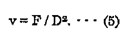
- Equation (5) the flow velocity "v" of fluid can be expressed using a flow rate F of fluid flowing in the flow path and the equivalent diameter D of the flow path by Equation (5) as follows:
- Equation (6) F / D 2 .
- ⁇ p 32 ⁇ ⁇ L / D 4 ⁇ F .
- the entire pressure loss of the second introduction channel 12 is taken as ⁇ p 1 .
- the pressure loss ⁇ p 1 is the sum of a pressure loss ⁇ p 2 of the small diameter part 12e constituting, in part, the second introduction channel 12 and a pressure loss ⁇ p 3 of the large diameter part 12f also constituting, in part, the second introduction channel 12, the entire pressure loss ⁇ p 1 can be expressed by Equation (7), taking the flow path length as L 2 and the equivalent diameter as D 2 for the small diameter part 12e, and taking the flow path length as L 3 and the equivalent diameter as D 3 for the large diameter part 12f as follows:
- the ratio of the flow path length L 2 of the small diameter part 12e and the flow path length L 3 of the large diameter part 12f is defined to ensure that the value of L 2 / D 2 4 + L 3 / D 3 4 is unchanged for each second introduction channel 12 under conditions that the equivalent diameter D 2 of the small diameter part 12 is equal for each second introduction channel 12 and the equivalent diameter D 3 of the large diameter part 12f is also equal for each second introduction channel 12.
- Each of the merging regions 14 is continuously disposed on downstream sides of the corresponding first introduction channel 10 and second introduction channel 12, and linearly extended along the same direction as the corresponding first introduction channel 10 and the second straight section 12c of the second introduction channel 12.
- the merging region 14 allows the first feedstock fluid having passed through the first introduction channel 10 and the second feedstock fluid having passed through the second introduction channel 12 to merge with each other while flowing along the longitudinal direction of the first flow path structure 1a.
- each merging region 14 has a cross sectional shape formed, as shown in FIG. 9 , with two semicircles bonded to each other in the vicinity of vertexes of their arcs, and has an equivalent diameter greater than the equivalent diameters of both the first introduction channel 10 and the second introduction channel 12.
- Each of the reaction channels 16 is continuously disposed on a downstream side of the corresponding merging region 14, and linearly extended along the same direction as the merging region 14, i.e. the longitudinal direction of the first flow path structure 1a.
- the reaction channel 16 causes the first feedstock fluid and the second feedstock fluid merged in the merging region 14 to react with each other while flowing along the longitudinal direction of the first flow path structure 1a.
- each reaction channel 16 has an equal flow path length.
- each reaction channel 16 has a semicircular shape in cross section, and has an equivalent diameter greater than that of the large diameter parts 12f of the second introduction channel 12.
- a plurality of heating medium flow paths 30 in which the heating medium is distributed is formed as described above, and the second flow path structure 1b is composed of a heating medium flow path plate 26 and a sealing plate 28 laminated on a surface of the heating medium flow path plate 26.
- the plurality of heating medium flow paths 30 is arranged along a width direction of the second flow path structure 1b at regular intervals in the second flow path structure 1b, as shown in Fig. 1 .
- Each heating medium flow path 30 is disposed on a position corresponding to each first introduction channel 10, the second straight section 12c of each second introduction channel 12, each merging region 14, and each reaction channel 16 in the first flow path structure 1a so as to linearly extend along the same direction as these channels, section and region.
- a plurality of grooves 32 is formed with openings located on the surface of the heating medium flow path plate 26, and the above-described heating medium flow paths 30 are formed by sealing the openings of the grooves 32 with the sealing plate 28.
- the sealing plate 28 also functions as the sealing plate 8 constituting, in part, the first flow path structure 1a.
- the first feedstock fluid is introduced from the feedstock supplying unit into the first introduction channel 10 in each reactive flow path 2, while the second feedstock fluid is introduced from the another feedstock supplying unit different from the above-described feedstock supplying unit into the second introduction channel 12 in each reactive flow path 2.
- the first feedstock fluid is caused to flow in the first introduction channels 10 under a condition of forming the streamline flow
- the second feedstock fluid is also caused to flow in the second introduction channels 12 under the condition of forming the streamline flow. Due to a fact that the entire pressure loss is equalized for each of the introduction channels 10, the first feedstock fluid is distributed to the first introduction channels 10 at the same flow rate. Also, due to a fact that the entire pressure loss is equalized for each of the second introduction channels 12, the second feedstock fluid is distributed to the second introduction channels 12 at the same flow rate.
- the first feedstock fluid having passed through the first introduction channels 10 is merged in the merging regions 14 with the second feedstock fluid having passed through the second introduction channels 12, and the merged first and second introduction fluids further flow from the merging regions 14 into the reaction channels 16 while reacting with each other, to thereby yield a predetermined reaction product.
- each second introduction channel 12 in the reactive flow path 2 has a different flow path length
- the equivalent diameter of each part in the second introduction channel 12 is defined in accordance with the flow path length of the second introduction path 12 to ensure that the entire pressure loss is equal for each second introduction channel 12, it is possible that the flow rate of the second feedstock fluid flowing in each second introduction channel 12 having a different flow path length is made equal to each other in this embodiment.
- the entire pressure loss can be equalized for each second introduction channel 12 by appropriately defining both the flow path length of each second introduction channel 12 and the equivalent diameter of each part of the second introduction channel 12, which can, in turn, ensure that the flow rate of the second feedstock fluid flowing in each second introduction channel 12 is equal to each other.
- flexibility in shape of each second introduction channel 12 can be increased in this embodiment. In this embodiment, therefore, the equal flow rate of the second feedstock fluid flowing in each second introduction channel 12 having a different flow path length is ensured, while at the same time the increased flexibility in shape of the second introduction channel 12 can be achieved.
- each second introduction channel 12 because the entire pressure loss is equalized for each second introduction channel 12 by changing the ratio of lengths of the small diameter part 12e and the large diameter part 12f depending on the flow path length of the second introduction channel 12, adjustment to each shape of the second introduction channels 12 is facilitated as compared to a case where the entire pressure loss is equalized for each second introduction channels 12 by gradually changing an overall equivalent diameter of each second introduction channel 12.
- each second introduction channel 12 having the different flow path length can be easily formed in a shape in which the second introduction channel 12 is able to have the equal entire pressure loss.
- each second introduction channel 12 is bent toward the same direction at the bent section 12d, and the more outer the introduction channel 12 is located at the bent section 12d, the ratio of length of the small diameter part 12e thereof is made smaller. In this way, even though each second introduction channel 12 bent toward the same direction has a different flow path length, the entire pressure loss can be equalized for each of the introduction channels 12, to thereby make the flow rate of the second feedstock fluid flowing in each second introduction channel 12 equal to each other, and also enhance flexibility in shape of the second introduction channel 12.
- first introduction channel 10 and the second introduction channel 12 respectively extend along mutually different directions from the inlet 10a and the inlet 12a disposed on mutually different locations, and the bent section 12d of each second introduction channel 12 changes the extending direction of the second introduction channel 12 to the direction identical to that of the corresponding first introduction channel 10 in this embodiment.
- This allows the first introduction channel 10 and the second introduction channel 12 to be joined to the merging region 14 from the same direction even though each first introduction channel 10 and each second introduction channel 12 have the inlets 10a (12a) on the different locations.
- the first feedstock fluid and the second feedstock fluid which are fed along the mutually different directions from the mutually different locations, can be merged with each other along the same direction.
- the reactor in this embodiment includes the plurality of first flow path structures 1a laminated on top of the other, the overall number of flow paths in the reactor can be increased, to thereby produce a greater amount of the reaction products.
- first and second introduction channels, the merging regions, and the reaction channels are not limited to those illustrated in the above embodiment, and the first and second introduction channels, the merging regions, and the reaction channels may be formed and placed in various configurations other than those indicated above.
- merging regions 42 may be formed so as to connect downstream ends of the first introduction channels 36 and downstream ends of the second introduction channels 38 to upstream ends of the reaction channels 40.
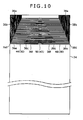
- FIG. 10 shows a configuration of a front surface of the flow path plate 34 according to the first modification example
- FIG- 11 shows a configuration of a rear surface of the flow path plate 34.
- a plurality of first introduction grooves 44 constituting a plurality of the first introduction channels 36 and a plurality of second introduction grooves 46 constituting a plurality of the second introduction channels 38 are formed on the front surface of the flow path plate 34.
- a plurality of reaction grooves 48 constituting a plurality of the reaction channels 40 is formed on the rear surface of the flow path plate 34.
- through holes 50 constituting the merging regions 42 are disposed so as to join each downstream end of the first introduction grooves 44 and each downstream end of the second introduction grooves 46 with each upstream end of the reaction grooves 48.
- the through holes 50 are formed penetrating the flow path plate 34 in a thickness direction.
- each first introduction channel 36 has a first straight section 36b linearly extended from the inlet 36a along the longitudinal direction of the first flow path structure 1a, a second straight section 36c linearly extended along the width direction of the first flow path structure 1a and joined to the corresponding merging region 42, and a bent section 36d disposed between both of the straight sections 36b, 36c to change a direction of the introduction channel from the longitudinal direction to the width direction of the first flow path structure 1a.
- each first introduction channel 36 is composed of a small diameter part 36e having a predetermined equivalent diameter and a large diameter part 36f having an equivalent diameter greater than that of the small diameter part 36e.
- the small diameter part 36e constitutes an area covering the first straight section 36b, the bent section 36d, and a portion of the second straight section 36c spanning a predetermined length from a bent section 36d side, while the large diameter part 36f constitutes the remaining portion of the second straight section 36c other than the portion of the small diameter part 36e.
- each first introduction channel 36 is configured such that the more outer the first introduction channel 36 is located at the bent section 36d, the ratio of length of the small diameter part 36e thereof is made smaller. In this way, the entire pressure loss becomes equal for each first introduction channel 36 having a different flow path length, and the flow rate of the first feedstock fluid flowing in the first introduction channel 36 is accordingly made equal to each other.
- each second introduction channel 38 has a structure obtained by inversing each first introduction channel 36 about a center line of the flow path plate 34 in the width direction. Specifically, each second introduction channel 38 has a first straight section 38b, a second straight section 38c, and a bent section 38d corresponding to the first straight section 36b, the second straight section 36c, and the bent section 36d, respectively. Further, each second introduction channel 38 is composed of a small diameter part 38e having a predetermined equivalent diameter and a large diameter part 38f whose equivalent diameter is greater than the small diameter part 38e. Each second introduction channel 38 is also configured such that the more outer the second introduction channel 38 is located at the bent section 38d, the ratio of length of the small diameter part 38e thereof is made smaller. In this way, the entire pressure loss is equalized for each second introduction channel 38 having a different flow path length, and the flow rate of the second feedstock fluid flowing in the second introduction channel 38 is accordingly made equal to each other.
- each first introduction channel 36 and each second introduction channel 38 are joined to the corresponding merging region 42 from mutually opposite directions.
- Each merging region 42 is disposed on a central area of the first flow path structure 1a in the width direction. That is, in this first modification example, the first feedstock fluid introduced from the inlet 36a on the one end in the longitudinal direction of the first flow path structure 1a into each first introduction channel 36 and the second feedstock fluid introduced from the inlet 38a on the same one end of the first flow path structure 1a into each second introduction channel 38 are both caused to flow along the longitudinal direction, and subsequently caused to flow toward an inner side in the width direction of the first flow path structure 1a, approaching each other until they are merged in the merging region 42 located on the central area of the first flow path structure 1a in the width direction.
- each reaction channel 40 is arranged on the rear side of the flow path plate 34 so as to be joined to each merging region 42. Accordingly, the first feedstock fluid and the second feedstock fluid merged at the merging section 42 are passed through the merging region 42 into the reaction channel 40 located on the rear side of the flow path plate 34, and caused to react with each other while flowing through the reaction channel 40.
- each reaction channel 40 is extended while bending several times to an outlet 40a which is disposed on a side surface of the first flow path structure 1a in the width direction.
- Each reaction channel 40 is formed so as to have the same flow path length. In this way, the pressure losses become equal for each reaction channel 40, and the flow rate is accordingly made equal for each reaction channel 40.
- the ratio between lengths of the small diameter part 36e and the large diameter part 36f is defined in accordance with the flow path length of each first introduction channel 36 to ensure that the entire pressure loss is equalized for each first introduction channel 36 having a different flow path length, while the ratio between lengths of the small diameter part 38e and the large diameter part 38f is defined in accordance with the flow path length of each second introduction channel 38 to ensure that the entire pressure loss is equalized for each second introduction channel 38 having a different flow path length.
- each first introduction channel 36 can be enhanced while achieving the equal flow rate of the first feedstock fluid flowing in each first introduction channel 36
- flexibility in shape of each second introduction channel 38 can be also enhanced while achieving the equal flow rate of the second feedstock fluid flowing in each second introduction channel 38.
- each first introduction channel 36 and each second introduction channel 38 in the first modification example their effects other than those indicated above are identical to the effects related to the second introduction channel 12 in the above embodiment.
- the configuration is not limited to that of the first modification example, and either one of the first introduction channels 36 or the second introduction channels 38 may be linearly extended from a lateral end of the first flow path structure 1a along the width direction, and joined at the merging sections 42 to bendingly extended introduction channels which are of the other of the first introduction channels 36 or the second introduction channels 38.
- each introduction channel linearly extending from the lateral end of the first flow path structure 1a in the width direction will be formed so as to have the same equivalent diameter throughout the length.
- each first introduction channel 10 disposed on the front surface side of the flow path plate 4 is formed so as to linearly extend along the longitudinal direction of the first flow path structure 1a
- each second introduction channel 12 disposed on the rear surface side of the flow path plate 4 is formed in the bent shape
- the first and second introduction channels 10 and 12 are not limited to the above-described configuration.
- each first introduction channel 10 may be formed, similarly with the second introduction channel 12, in the bent shape and may be composed of a small diameter part and a large diameter part.
- first flow path structure 1a in which the first introduction channels 10 and the second introduction channels 14 are joined together at the merging regions 14 has been described by way of illustration in the above embodiment, the present invention is not limited to the configuration. Specifically, this invention may be applied to a flow path structure having a flow path which extends from one introduction channel without joining another introduction channel.
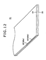
- a flow path structure 61 for example, according to a second modification example of the embodiment is shown in FIG. 12 .
- the flow path structure 61 in the second modification example composed of a flow path plate 64 and a sealing plate 66 includes a plurality of flow paths 68 disposed only on a rear surface side of the flow path plate 64.
- An inlet 68a of each flow path 68 is arranged on one end in a width direction of the flow path structure 61.
- each flow path 68 includes a first straight section 68b, a second straight section 68c, and a bent section 68d as shown in FIG. 13 .
- the first straight section 68b is a portion linearly extending from the inlet 68a along the width direction of the flow path structure 61
- the second straight section 68c is a portion linearly extending along a longitudinal direction of the flow path structure 61.
- the bent section 68d is a portion located between the first straight section 68d and the second straight section 68c to change a direction of the flow path 68 from the width direction to the longitudinal direction of the flow path structure 61.
- each flow path 68 is composed of a small diameter part 68e having a predetermined equivalent diameter and a large diameter part 68f having an equivalent diameter greater than that of the small diameter part 68e.
- the small diameter part 68e corresponds to an area covering the first straight section 68b, the bent section 68d, and a portion of the second straight section 68c spanning a predetermined length from a bent section 68d side, whereas the large diameter part 68f corresponds to the remaining second straight section 68c other than the area forming the small diameter part 68e.
- the small diameter part 68e in each flow path 68 has a structure similar to that of the small diameter part 12a in each second introduction channel 12 of the above-described embodiment.
- the large diameter part 68f in each flow path 68 has a structure obtained by linearly extending the large diameter part 12f in each second introduction channel 12 of the above-described embodiment toward a downstream side to an end of the flow path structure 61. Then, also in the second modification example, the more outer the flow path 68 is located at the bent section 68d, the ratio of length of the small diameter part 68e thereof is made smaller as similarly as the above embodiment. In this way, the entire pressure loss is equalized for each flow path 68 having a different flow path length.
- each flow path 68 because the ratio of lengths of the small diameter part 68e and the large diameter part 68f is defined in accordance with the flow path length of each flow path 68 to ensure that the entire pressure loss is equal for each flow path 68 having a different flow path length, flexibility in shape of each flow path 68 can be enhanced while achieving the equal flow rate of fluid flowing in each flow path 68 according to the principle analogous to that of the above-described embodiment.
- the present invention is not limited to the thus-described configuration.
- the flow path structure of this invention may be used in any types, other than the reactor, of apparatus for handling a fluid, such as a heat exchanger.
- the flow path structure 61 according to the second modification example may be applied.
- a flow path structure includes therein a plurality of flow paths into which a fluid is introduced, wherein: the plurality of flow paths includes flow paths each having a different flow path length, and an equivalent diameter of each part in each flow path is defined in accordance with the flow path length of the flow path to ensure that an entire pressure loss is equal for each of the flow paths.
- the equivalent diameter of each part in each flow path is defined in accordance with the flow path length of each flow path to ensure that the entire pressure loss is equalized for each flow path, which allows the flow rate of fluid flowing in each flow path to be equal to each other even when each flow path has a different flow path length. Further, in this flow path structure, because the equivalent diameter of each part in each flow path is determined in accordance with the flow path length of each flow path, both the flow path length of each flow path and the equivalent diameter of each part in each flow path may be defined as appropriate to equalize the entire pressure loss for each flow path, and in turn make the flow rate of fluid flowing in each flow path equal to each other.
- each of the flow paths includes a small diameter part having a predetermined equivalent diameter and a large diameter part having an equivalent diameter greater than that of the small diameter part, and a ratio of lengths of the small diameter part and the large diameter part is determined in accordance with the flow path length of each flow path to ensure that the entire pressure loss is equal for each of the flow paths.
- the pressure loss is to be equalized for each flow path by appropriately determining an overall equivalent diameter of each flow path depending on the flow path length of each flow path.
- the overall equivalent diameter should be gradually varied for each flow path within a very small range depending on the flow path length of each flow path, and it is extremely difficult to form each flow path with high accuracy in such a manner that the overall equivalent diameter is varied just slightly for each flow path.
- each flow path can be easily formed in the shape in which the equal entire pressure loss can be realized for each flow path.
- each of the flow paths is arranged in parallel and bent toward a same direction. It is also preferable that each flow path located on an outer side at an area being bent has a flow path length greater than that of those located on an inner side, and the more outer each flow path is located at the area being bent, the flow path has a smaller ratio of length of the small diameter part.
- each flow path is bent toward the same direction and has a different flow path length
- the entire pressure loss can be equalized for each flow path, to thereby realize the equal flow rate of fluid flowing in each flow path while allowing for increased flexibility in flow path shape.
- the reactor according to this embodiment includes a flow path structure in which a plurality of reactive flow paths is formed for causing a first feedstock fluid to react with a second feedstock fluid
- each of the reactive flow paths includes a first introduction channel in which the first feedstock fluid is introduced, a second introduction channel in which the second feedstock fluid is introduced, a merging region joined to the first introduction channel and the second introduction channel on their down streamside for allowing the first feedstock fluid to merge with the second feedstock fluid, and a reaction channel joined to the merging region on a downstream side of the merging region for causing the first feedstock fluid and the second feedstock fluid to react with each other; at least one of a group consisting of the first introduction channel in each reactive flow path or a group consisting of the second introduction channel in each reactive flow path includes the introduction channels each having a different flow path length, and an equivalent diameter of each part of each introduction channel is defined in accordance with the flow path length of each introduction channel to ensure that an entire pressure loss is equalized for each of the introduction channels in the
- the equal flow rate of the feedstock fluid flowing in each introduction channel in the group including the introduction channels each having a different flow path length can be realized because the equivalent diameter of each part in each introduction channel is determined depending on the flow path length of each introduction channel to ensure that the entire pressure loss is equal for each introduction channel in the group including the introduction channels each having a different flow path length.
- both the flow path length and the equivalent diameter of each part in each flow path channel may be defined as appropriate to thereby equalize the entire pressure loss for each introduction channel, and to, in turn, realize the equal flow rate of the feedstock fluid flowing in each introduction channel.
- the flexibility in shape of each introduction channel in the group including the introduction channels each having a different flow path length can be increased as compared with the case where the flow path lengths are made uniform for each introduction channel, to thereby obtain the equal flow rate for each introduction channel. Accordingly, in the reactor, the equal flow rate of the feedstock fluid flowing in each introduction channel in the group including the introduction channels each having a different flow path length can be realized, while at the same time the flexibility in shape of each introduction channel can be enhanced.
- each introduction channel in the group including the introduction channels each having a different flow path length includes a small diameter part having a predetermined equivalent diameter and a large diameter part having an equivalent diameter greater than that of the small diameter part, and a ratio of lengths of the small diameter part and the large diameter part is determined depending on the flow path length of each introduction channel to ensure that the entire pressure loss is equalized for each of the introduction channels.
- the pressure loss is to be equalized for each introduction channel by appropriately determining an overall equivalent diameter of each introduction channel depending on the flow path length of each introduction channel.
- the overall equivalent diameter should be gradually varied for each introduction channel within a very small range depending on the flow path length of each introduction channel, and it is extremely difficult to form each introduction channel with high accuracy in such a manner that the overall equivalent diameters is varied just slightly for each introduction channel.
- each introduction channel in the group including the introduction channels each having a different flow path length can be easily formed in the shape in which the equal entire pressure loss can be realized for each introduction channel.
- each of the introduction channels in the group including the introduction channels each having a different flow path length is arranged in parallel and bent toward a same direction. It is also preferable that each introduction channel located on an outer side at an area being bent has a flow path length greater than that of those located on an inner side, and the more outer each introduction channel is located at the area being bent, the introduction channel has a smaller ratio of length of the small diameter part.
- each introduction channel in the group including the introduction channels each having a different flow path length is bent toward the same direction, the entire pressure loss can be equalized for each introduction channel, to thereby realize the equal flow rate of feedstock fluid flowing in each introduction channel, while allowing for increased flexibility in shape of each introduction channel.
- each of the first introduction channels and each of the second introduction channels may be respectively provided with inlets on mutually different locations, extended from the inlets along mutually different directions, and joined to the merging region from the same direction, and each introduction channel in at least one of the first introduction channels or the second introduction channels may include a bent region for changing an extending direction to a direction identical to that of each introduction channel in the other of the first introduction channels or the second introduction channels.
- each first introduction channel and each second introduction channel can be joined to the merging region from the same direction by changing the extending direction of at least one of the first introduction channel and the second introduction channel through the bent section. In this way, it is possible to form the reactor capable of merging the first feedstock fluid and the second feedstock fluid with each other along the same direction while allowing both of the feedstock fluids to flow from the mutually different locations along the mutually different directions.
- the above-described reactor may preferably include a plurality of the flow path structures laminated on top of the other. In such a configuration, the number of flow paths can be increased in the overall reactor to thereby yield a greater amount of reaction products.
- reaction method using the reactor according to this embodiment is implemented using any one of the above-described reactors, in which the feedstock fluid is fed into each introduction channel in the group including the introduction channels each having a different flow path length under the condition of forming the streamline flow.
Landscapes
- Chemical & Material Sciences (AREA)
- Organic Chemistry (AREA)
- Chemical Kinetics & Catalysis (AREA)
- Engineering & Computer Science (AREA)
- Physics & Mathematics (AREA)
- Thermal Sciences (AREA)
- Mechanical Engineering (AREA)
- General Engineering & Computer Science (AREA)
- Physical Or Chemical Processes And Apparatus (AREA)
Abstract
Description
- The present invention relates to a flow path structure, a reactor, and a reaction method using the reactor.
- Conventionally, there have been known flow path structures internally including small flow paths into which fluid is introduced. For example, Patent Document 1 listed below teaches a reactor including such a flow path structure.
- In the reactor disclosed in Patent Document 1, a plurality of small flow paths is parallelly arranged inside the flow path structure. A first feedstock fluid and a second feedstock fluid are introduced into each flow path from an end thereof. Then, a desired product is prepared by causing the first feedstock fluid and the second feedstock fluid to react with each other while flowing through each flow path toward its outlet side.
- Here, when the plurality of flow paths is formed in the flow path structure as described above, it is desired that the flow rate of the fluid flowing through each flow path be equal to each other. For example, in a heat exchanger described in
Patent Document 2, a pressure loss in each flow path is equalized among the flow paths by making flow path lengths uniform for each flow path, so that the flow rate of the fluid flowing in the flow path becomes equal to each other. - However, such an attempt of making the flow path lengths uniform for each flow path will pose a severe restriction on shape of each flow path, leading to a problem in that it becomes difficult to freely design the flow path.
- Patent Document 1: Published Japanese Translation of Unexamined PCT Patent Application No.
2005-525229 - Patent Document 2: Japanese Patent Laid-Open Publication No.
S64-3496 - It is an object of the present invention to increase flexibility in shape of each flow path while ensuring that a flow rate of fluid flowing in each flow path is equal to each other.
- According to an aspect of this invention, a flow path structure includes therein a plurality of flow paths into which a fluid is introduced, wherein: the plurality of flow paths includes flow paths each having a different flow path length, and an equivalent diameter of each part in each flow path is defined in accordance with the flow path length of the flow path to ensure that an entire pressure loss is equal for each of the flow paths.
- According to another aspect of this invention, a reactor includes a flow path structure in which a plurality of reactive flow paths is formed for causing a first feedstock fluid to react with a second feedstock fluid, wherein; each of the reactive flow paths includes a first introduction channel in which the first feedstock fluids is introduced, a second introduction channel in which the second feedstock fluid is introduced, a merging region joined to the first introduction channel and the second introduction channel on their down streamside for allowing the first feedstock fluid to merge with the second feedstock fluid, and a reaction channel joined to the merging region on a downstream side of the merging region for causing the first feedstock fluid and the second feedstock fluid to react with each other; at least one of a group consisting of the first introduction channel in each reactive flow path or a group consisting of the second introduction channel in each reactive flow path includes the introduction channels each having a different flow path length, and an equivalent diameter of each part of each introduction channel is defined in accordance with the flow path length of each introduction channel to ensure that an entire pressure loss is equalized for each of the introduction channels in the group including the introduction channels each having a different flow path length.
-
-
FIG. 1 is a perspective view of a flow path apparatus constituting a reactor according to an embodiment of the present invention; -
FIG. 2 is an exploded perspective view of a first flow path structure constituting the flow path apparatus shown inFIG. 1 ; -
FIG. 3 is a schematic diagram showing a positional relationship of a group of first introduction channels, a group of second introduction channels, a group of merging regions, and a group of reaction channels in a first flow path structure; -
FIG. 4 is a cross sectional view taken along the first introduction channel and the reaction channel in the first flow path structure constituting the flow path apparatus shown inFIG. 1 ,; -
FIG. 5 is a plan view showing a front surface side of a flow path plate partly constituting the first flow path structure; -
FIG. 6 is an enlarged view showing a portion A ofFIG. 5 ; -
FIG. 7 is a plan view showing a rear surface side of the flow path plate partly constituting the first flow path structure; -
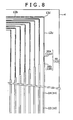
FIG. 8 is an enlarged view showing a portion B ofFIG. 7 ; -
FIG. 9 is a cross sectional view of the flow path plate taken along a line IX-IX ofFIG. 5 ; -
FIG. 10 is a plan view showing a front surface side of a flow path plate in a first modification example of the embodiment according to the present invention; -
FIG. 11 is a plan view showing a rear surface side of the flow path plate in the first modification example depicted inFIG. 10 ; -
FIG. 12 is a perspective view of a flow path structure in a second modification example of the embodiment according to the present invention, and -
FIG. 13 is a plan view showing a configuration of the flow paths in the flow path structure in the second modification example depicted inFIG. 12 . - Hereinafter, an embodiment of the present invention will be described with reference to the drawings.
- Referring first to
FIGS. 1 to 9 , a reactor according to an embodiment of this invention and a configuration or a firstflow path structure 1a contained in the reactor will be described. - The reactor according to this embodiment has a flow path apparatus S as shown in
FIG. 1 . The flow path apparatus S is configured by alternately laminating the firstflow path structures 1a in which a plurality ofreactive flow paths 2 is formed for allowing a feedstock fluid to flow therein and secondflow path structures 1b in which a plurality of heatingmedium flow paths 30 is formed for allowing a heating medium to flow therein. It should be noted that the firstflow path structure 1a is embraced in a concept of the flow path structure of this invention. - Then, the reactor according to this embodiment produces a predetermined reaction product by causing two feedstock fluids of a first feedstock fluid and a second feedstock fluid to react with each other while flowing through a plurality of minute
reactive flow paths 2 provided in the firstflow path structure 1a. - In particular, the first
flow path structure 1a is composed of aflow path plate 4 and a pair ofsealing plates FIG. 4 . Theflow path plate 4 and the pair ofsealing plates flow path plate 4 is inserted between thesealing plates flow path structure 1a. Then, in the firstflow path structure 1a, the plurality ofreactive flow paths 2 is arranged at regular intervals along a width direction of the firstflow path structure 1a. Eachreactive flow path 2 is composed of afirst introduction channel 10 into which the first feedstock fluid is introduced, asecond introduction channel 12 into which the second feedstock fluid is introduced, amerging region 14 which is joined to thefirst introduction channel 10 and thesecond introduction channel 12 on their downstream sides to merge the first feedstock fluid with the second feedstock fluid, and areaction channel 16 which is joined to the mergingregion 4 on a downstream side of themerging region 4 for causing the first feedstock fluid and the second feedstock fluid to react with each other. - Each of the
reactive flow paths 2 is formed by sealing openings of grooves formed in theflow path plate 4. Specifically, a plurality offirst introduction grooves 18 is formed as shown inFIGS. 5 and6 with openings located on a front surface of theflow path plate 4, while a plurality of second introduction grooves 20 and a plurality ofreaction grooves 22 are formed as shown inFIGS. 7 and8 with openings located on a rear surface of theflow path plate 4. Each of thesecond introduction grooves 20 is composed of asmall diameter groove 20a constituting asmall diameter part 12e, which will be described below, and alarge diameter groove 20b having a width greater than that of thesmall diameter groove 20a and constituting alarge diameter part 12f, which will be described below. In addition, athrough hole 24 penetrating theflow path plate 4 in a width direction is formed on a location where both downstream ends of thefirst introduction groove 18 and thesecond introduction groove 20 are joined to an upstream end of thereaction groove 22. - Then, the
first introduction channels 10 are formed by laminating, as shown inFIG. 2 , thesealing plate 6 on the front surface of theflow path plate 4 to seal the openings of thefirst introduction grooves 18. On the other hand, by laminating thesealing plate 8 on the rear surface of theflow path plate 4, the openings of thesecond introduction grooves 20 are sealed, to thereby form thesecond introduction channels 12, while the openings of thereaction grooves 22 are sealed, to thereby form thereaction channels 16. Further, themerging regions 14 are formed by sealing both open ends of the throughholes 24 with thesealing plates - Further, in the first
flow path structure 1a, a group consisting of thefirst introduction channel 10 in eachreactive flow path 2, a group consisting of thesecond introduction channel 12 in eachreactive flow path 2, a group consisting of the mergingregion 14 in eachreactive flow path 2, and a group consisting of thereaction channel 16 in eachreactive flow path 2 are respectively arranged in a positional relationship as shown inFIG. 3 . - Each
first introduction channel 10 allows the first feedstock fluid to flow from one end in a longitudinal direction of the firstflow path structure 1a along the longitudinal direction into eachmerging region 14. Eachsecond introduction channel 12 firstly allows the second feedstock fluid to flow from one end in a width direction of the firstflow path structure 1a along the width direction, and subsequently changes a flowing direction at some midpoint by 90° for causing the second feedstock fluid to flow along the longitudinal direction of the firstflow path structure 1a the same as that of the first feedstock fluid, so that the second feedstock fluid is merged with the first feedstock fluid from the same direction in each mergingregion 14. Further, eachreaction channel 16 causes the first feedstock fluid and the second feedstock fluid merged in each mergingregion 14 to react with each other while linearly flowing along the longitudinal direction of the firstflow path structure 1a. - More specifically, each of the
first introduction channels 10 includes aninlet 10a at the one end of the firstflow path structure 1a in the longitudinal direction. Further, eachfirst introduction channel 10 is linearly extended from theinlet 10a along the longitudinal direction, of the firstflow path structure 1a, and joined to corresponding mergingregion 14. Theinlet 10a of eachfirst introduction channel 10 is connected to a not-illustrated feedstock supplying unit from which the first feedstock fluid is distributed and introduced to thefirst introduction channel 10. Eachfirst introduction channel 10 has a semicircular shape in cross section and also has a fixed equivalent diameter over the entire length thereof. - Moreover, the
first introduction channels 10a are parallelly arranged at regular intervals along the width direction of the firstflow path structure 1a, and each of thefirst introduction channels 10 has the same flow path length and the same equivalent diameter. In this way, an entire pressure loss is equalized for eachfirst introduction channel 10. Then, when the entire pressure loss is equalized for eachfirst introduction channel 10, a flow rate of the first feedstock fluid distributed and fed from the feedstock supplying unit to thefirst introduction channel 10 is accordingly made equal to each other. - Each of the
second introduction channels 12 has aninlet 12a at the one end of the firstflow path structure 1a in the width direction. Theinlet 12a of eachsecond introduction channel 12 is connected to another not-illustrated feedstock supplying unit, which is different from the feedstock supplying unit for supplying the first feedstock fluid, and, from the another feedstock supplying unit, the second feedstock fluid is distributed and introduced to eachsecond introduction channel 12. - Further, each
second introduction channel 12 includes, as shown inFIG. 8 , a firststraight section 12b linearly extended from theinlet 12a along the width direction of the firstflow path structure 1a, i.e. a direction orthogonal to each of thefirst introduction channels 10, a secondstraight section 12c linearly extended.along the longitudinal direction of the firstflow path structure 1a, i.e. along each of thefirst introduction channels 10 and joined to thecorresponding merging region 14, and abent section 12d disposed in-between the above-described two sections to direct the introduction channel from the direction orthogonal to each of thefirst introduction channels 10 to a direction the same as that of thefirst introduction channels 10. In other words, eachsecond introduction channel 12, having theinlet 12a at a location different from theinlet 10a of eachfirst introduction channel 10, is extended from theinlet 12a along the direction different from thefirst introduction channel 10, subsequently changed in direction by thebent section 12d, and joined to the correspond mergingregion 14 from the same direction as thefirst introduction channel 10. - In addition, each
second introduction channel 12 has a different flow path length. Specifically, eachsecond introduction channel 12 is parallelly arranged at regular intervals along the width direction of the firstflow path structure 1a, and bent through thebent section 12d toward the same direction. Eachsecond introduction channel 12 located on an outer side at thebent section 12d of thesecond introduction channel 12 has a flow path length greater than that of those located on an inner side. In other words, the more outer thesecond introduction channel 12 is located at thebent section 12d, the longer the flow path length thereof becomes. - Then, in this embodiment, the equivalent diameter of each part in each
second introduction channel 12 having a different flow path length is defined depending on the flow path length of thesecond introduction channel 12 in such a manner that the entire pressure loss is equalized for eachsecond introduction channel 12. - Particularly, each
second introduction channel 12 is composed of asmall diameter part 12e having a predetermined equivalent diameter and alarge diameter part 12f having an equivalent diameter greater than that of thesmall diameter part 12e. Thesmall diameter part 12e has a semicircular shape in cross section, and corresponds to an area covering the firststraight section 12b, thebent section 12d, and a portion of the secondstraight section 12c spanning a predetermined length from abent section 12d side. Thelarge diameter part 12f has a semicircular shape in cross section, and corresponds to the remaining portion of the secondstraight section 12e other than thesmall diameter part 12e. Then, a position of a connection between thesmall diameter part 12e and thelarge diameter part 12f is disposed such that the more inner theintroduction channel 12 is located at thebent section 12d, the gradually closer to the mergingregions 14 the position of a connection of theintroduction channel 12 becomes. - The entire pressure loss of each
second introduction channel 12 is determined from the sum of pressure losses of thesmall diameter part 12e and thelarge diameter part 12f that constitute thesecond introduction channel 12. In other words, the entire pressure loss of thesecond introduction channel 12 changes depending on a ratio of lengths of thesmall diameter part 12e and thelarge diameter part 12f. Here, in this embodiment, the ratio of lengths of thesmall diameter part 12e and thelarge diameter part 12f is defined in accordance with the flow path length of eachsecond introduction channel 12 in such a manner that the entire pressure losses are equal for eachsecond introduction channel 12. - Specifically, due to the equivalent diameter of the
small diameter part 12e smaller than that of thelarge diameter part 12f, the pressure loss in thesmall diameter part 12e is greater than the pressure loss in thelarge diameter part 12f Further, the more outer thesecond introduction channel 12 is located at thebent section 12d, thesecond introduction channel 12 has a longer flow path length as described above. Thus, the more outer thesecond introduction channel 12 is located, the larger the pressure loss of thesecond introduction channel 12 becomes in proportion to the flow path length. With this in view, in this embodiment, the more outer theintroduction channel 12 is located at thebent section 12d, the ratio of length of thesmall diameter part 12e thereof which exhibits a significant pressure loss is made smaller, to thereby equalize the entire pressure loss for eachsecond introduction channel 12. Then, when the entire pressure loss is equalized for eachsecond introduction channel 12, the flow rate of the second feedstock fluid flowing in eachsecond introduction channel 12 becomes equal to each other. - In addition, shapes of the
small diameter part 12e and thelarge diameter part 12f in eachsecond introduction channel 12 are determined based on a principle described below. - Namely, a pressure loss Δp of fluid flowing in a flow path is typically given by Fanning equation as follows:
-

- Further, Reynolds number Re denoting a condition of fluid disturbance is expressed by Equation (2) as follows:
-

- Then, the second feedstock fluid is fed to each
second induction channel 12 in a state where the second feedstock fluid is in a streamline flow region as described below. A flow of fluid is in the streamline flow region when the Reynolds number Re is in a range of Re<2100. In this case, the coefficient of fluid friction f is expressed by Equation (3) as follows: -

-

-
-

- Here, the entire pressure loss of the
second introduction channel 12 is taken as Δp1. Because the pressure loss Δp1 is the sum of a pressure loss Δp2 of thesmall diameter part 12e constituting, in part, thesecond introduction channel 12 and a pressure loss Δp3 of thelarge diameter part 12f also constituting, in part, thesecond introduction channel 12, the entire pressure loss Δp1 can be expressed by Equation (7), taking the flow path length as L2 and the equivalent diameter as D2 for thesmall diameter part 12e, and taking the flow path length as L3 and the equivalent diameter as D3 for thelarge diameter part 12f as follows: -

second induction channel 12 takes a value proportional to the flow rate F of the second feedstock fluid as long as a value of L2/D2 4+L3/D3 4 remains unchanged. In other words, given that the value of L2/D2 4+L3/D3 4 is unchanged, a relationship is established in which the flow rate F of the second feedstock fluid flowing in eachsecond introduction channel 12 is equal to each other when the entire pressure loss Δp1 is equal for eachsecond introduction channel 12. - Therefore, in this embodiment, the ratio of the flow path length L2 of the
small diameter part 12e and the flow path length L3 of thelarge diameter part 12f is defined to ensure that the value of L2 / D2 4 + L3 / D3 4 is unchanged for eachsecond introduction channel 12 under conditions that the equivalent diameter D2 of thesmall diameter part 12 is equal for eachsecond introduction channel 12 and the equivalent diameter D3 of thelarge diameter part 12f is also equal for eachsecond introduction channel 12. - Each of the merging
regions 14 is continuously disposed on downstream sides of the correspondingfirst introduction channel 10 andsecond introduction channel 12, and linearly extended along the same direction as the correspondingfirst introduction channel 10 and the secondstraight section 12c of thesecond introduction channel 12. The mergingregion 14 allows the first feedstock fluid having passed through thefirst introduction channel 10 and the second feedstock fluid having passed through thesecond introduction channel 12 to merge with each other while flowing along the longitudinal direction of the firstflow path structure 1a. Then, each mergingregion 14 has a cross sectional shape formed, as shown inFIG. 9 , with two semicircles bonded to each other in the vicinity of vertexes of their arcs, and has an equivalent diameter greater than the equivalent diameters of both thefirst introduction channel 10 and thesecond introduction channel 12. - Each of the
reaction channels 16 is continuously disposed on a downstream side of the corresponding mergingregion 14, and linearly extended along the same direction as the mergingregion 14, i.e. the longitudinal direction of the firstflow path structure 1a. Thereaction channel 16 causes the first feedstock fluid and the second feedstock fluid merged in the mergingregion 14 to react with each other while flowing along the longitudinal direction of the firstflow path structure 1a. Further, eachreaction channel 16 has an equal flow path length. Still further, eachreaction channel 16 has a semicircular shape in cross section, and has an equivalent diameter greater than that of thelarge diameter parts 12f of thesecond introduction channel 12. - In the second
flow path structure 1b, a plurality of heatingmedium flow paths 30 in which the heating medium is distributed is formed as described above, and the secondflow path structure 1b is composed of a heating mediumflow path plate 26 and a sealingplate 28 laminated on a surface of the heating mediumflow path plate 26. The plurality of heatingmedium flow paths 30 is arranged along a width direction of the secondflow path structure 1b at regular intervals in the secondflow path structure 1b, as shown inFig. 1 . Each heatingmedium flow path 30 is disposed on a position corresponding to eachfirst introduction channel 10, the secondstraight section 12c of eachsecond introduction channel 12, each mergingregion 14, and eachreaction channel 16 in the firstflow path structure 1a so as to linearly extend along the same direction as these channels, section and region. Further, a plurality ofgrooves 32 is formed with openings located on the surface of the heating mediumflow path plate 26, and the above-described heatingmedium flow paths 30 are formed by sealing the openings of thegrooves 32 with the sealingplate 28. It should be noted that the sealingplate 28 also functions as the sealingplate 8 constituting, in part, the firstflow path structure 1a. - Then, when a heating medium is fed from a not-illustrated heating medium supplying unit into the heating
medium flow paths 30 of the secondflow path structure 1b, heat is exchanged between the heating medium and the first and second feedstock fluids flowing through thereaction channels 16 in the firstflow path structure 1a, to thereby facilitate reaction between the first feedstock fluid and the second feedstock fluid in thereaction channels 16. - Next, a reaction method using the reactor according to this embodiment will be described.
- Firstly, in the reaction method using the reactor according to this embodiment, the first feedstock fluid is introduced from the feedstock supplying unit into the
first introduction channel 10 in eachreactive flow path 2, while the second feedstock fluid is introduced from the another feedstock supplying unit different from the above-described feedstock supplying unit into thesecond introduction channel 12 in eachreactive flow path 2. At this time, the first feedstock fluid is caused to flow in thefirst introduction channels 10 under a condition of forming the streamline flow, while the second feedstock fluid is also caused to flow in thesecond introduction channels 12 under the condition of forming the streamline flow. Due to a fact that the entire pressure loss is equalized for each of theintroduction channels 10, the first feedstock fluid is distributed to thefirst introduction channels 10 at the same flow rate. Also, due to a fact that the entire pressure loss is equalized for each of thesecond introduction channels 12, the second feedstock fluid is distributed to thesecond introduction channels 12 at the same flow rate. - Then, the first feedstock fluid having passed through the
first introduction channels 10 is merged in the mergingregions 14 with the second feedstock fluid having passed through thesecond introduction channels 12, and the merged first and second introduction fluids further flow from the mergingregions 14 into thereaction channels 16 while reacting with each other, to thereby yield a predetermined reaction product. - As described above, even when each
second introduction channel 12 in thereactive flow path 2 has a different flow path length, because the equivalent diameter of each part in thesecond introduction channel 12 is defined in accordance with the flow path length of thesecond introduction path 12 to ensure that the entire pressure loss is equal for eachsecond introduction channel 12, it is possible that the flow rate of the second feedstock fluid flowing in eachsecond introduction channel 12 having a different flow path length is made equal to each other in this embodiment. - Further, in this embodiment, because the equivalent diameter of each part in each
second introduction channel 12 is determined in accordance with each flow path length of thesecond introduction channel 12 having a different flow path length, the entire pressure loss can be equalized for eachsecond introduction channel 12 by appropriately defining both the flow path length of eachsecond introduction channel 12 and the equivalent diameter of each part of thesecond introduction channel 12, which can, in turn, ensure that the flow rate of the second feedstock fluid flowing in eachsecond introduction channel 12 is equal to each other. For this reason, as compared to a conventional case where the flow path lengths are made uniform for each introduction channel to ensure that the flow rate of feedstock fluid flowing in each flow channel is equal to each other, flexibility in shape of eachsecond introduction channel 12 can be increased in this embodiment. In this embodiment, therefore, the equal flow rate of the second feedstock fluid flowing in eachsecond introduction channel 12 having a different flow path length is ensured, while at the same time the increased flexibility in shape of thesecond introduction channel 12 can be achieved. - Still further, in this embodiment, because the entire pressure loss is equalized for each
second introduction channel 12 by changing the ratio of lengths of thesmall diameter part 12e and thelarge diameter part 12f depending on the flow path length of thesecond introduction channel 12, adjustment to each shape of thesecond introduction channels 12 is facilitated as compared to a case where the entire pressure loss is equalized for eachsecond introduction channels 12 by gradually changing an overall equivalent diameter of eachsecond introduction channel 12. In this way, eachsecond introduction channel 12 having the different flow path length can be easily formed in a shape in which thesecond introduction channel 12 is able to have the equal entire pressure loss. - Moreover, in this embodiment, each
second introduction channel 12 is bent toward the same direction at thebent section 12d, and the more outer theintroduction channel 12 is located at thebent section 12d, the ratio of length of thesmall diameter part 12e thereof is made smaller. In this way, even though eachsecond introduction channel 12 bent toward the same direction has a different flow path length, the entire pressure loss can be equalized for each of theintroduction channels 12, to thereby make the flow rate of the second feedstock fluid flowing in eachsecond introduction channel 12 equal to each other, and also enhance flexibility in shape of thesecond introduction channel 12. - In addition, the
first introduction channel 10 and thesecond introduction channel 12 respectively extend along mutually different directions from theinlet 10a and theinlet 12a disposed on mutually different locations, and thebent section 12d of eachsecond introduction channel 12 changes the extending direction of thesecond introduction channel 12 to the direction identical to that of the correspondingfirst introduction channel 10 in this embodiment. This allows thefirst introduction channel 10 and thesecond introduction channel 12 to be joined to the mergingregion 14 from the same direction even though eachfirst introduction channel 10 and eachsecond introduction channel 12 have theinlets 10a (12a) on the different locations. In this way, the first feedstock fluid and the second feedstock fluid, which are fed along the mutually different directions from the mutually different locations, can be merged with each other along the same direction. - Further, because the reactor in this embodiment includes the plurality of first
flow path structures 1a laminated on top of the other, the overall number of flow paths in the reactor can be increased, to thereby produce a greater amount of the reaction products. - Still further, in this embodiment, because the second feedstock fluid is caused to flow under the condition of forming the streamline flow in each second introduction channel, a causal connection can be established in which the flow rate of the second feedstock fluid flowing in each
second introduction channel 12 is equal to each other as long as the entire pressure loss is equalized for eachsecond introduction channel 12, provided that a predetermined relationship is satisfied between the flow path length and equivalent diameter of thesmall diameter part 12e and the flow path length and equivalent diameter of thelarge diameter parts 12f in eachsecond introduction channel 12. - Note that the embodiment disclosed herein should be considered in all aspects as illustrative and not restrictive. The scope of this invention is defined not by description of the embodiment set forth above but by the appended claims, and intended to include all changes falling within the scope of the claims either literally or under the doctrine of equivalents.
- Namely, the geometry and placement of the first and second introduction channels, the merging regions, and the reaction channels are not limited to those illustrated in the above embodiment, and the first and second introduction channels, the merging regions, and the reaction channels may be formed and placed in various configurations other than those indicated above.
- For example, as with a first modification example of the above embodiment depicted in
FIGS. 10 and11 , in addition to providing bothfirst introduction channels 36 andsecond introduction channels 38 on a front surface side of aflow path plate 34, and providingreaction channels 40 on a rear surface side of theflow path plate 34, mergingregions 42 may be formed so as to connect downstream ends of thefirst introduction channels 36 and downstream ends of thesecond introduction channels 38 to upstream ends of thereaction channels 40. - Specifically,
FIG. 10 shows a configuration of a front surface of theflow path plate 34 according to the first modification example, and FIG- 11 shows a configuration of a rear surface of theflow path plate 34. - In the first modification example, a plurality of
first introduction grooves 44 constituting a plurality of thefirst introduction channels 36 and a plurality ofsecond introduction grooves 46 constituting a plurality of thesecond introduction channels 38 are formed on the front surface of theflow path plate 34. Further, a plurality ofreaction grooves 48 constituting a plurality of thereaction channels 40 is formed on the rear surface of theflow path plate 34. In addition, throughholes 50 constituting the mergingregions 42 are disposed so as to join each downstream end of thefirst introduction grooves 44 and each downstream end of thesecond introduction grooves 46 with each upstream end of thereaction grooves 48. The through holes 50 are formed penetrating theflow path plate 34 in a thickness direction. - Then, when openings of the
first introduction grooves 44 and of thesecond introduction grooves 46 are sealed by covering the front surface of theflow path plate 34 with a sealing plate which is not illustrated in the figure, thefirst introduction channels 36 and thesecond introduction channels 38 are formed. On the other hand, when openings of thereaction grooves 48 are sealed by covering the rear surface of theflow path plate 34 with the not-illustrated sealing plate, thereaction channels 40 are formed. Further, when both open ends of the throughholes 50 are sealed by both of the sealing plates, the mergingregions 42 are formed. - Both an
inlet 36a of eachfirst introduction channel 36 and aninlet 38a of eachsecond introduction channel 38 are disposed on one end in the longitudinal direction of the firstflow path structure 1a (refer toFIG. 1 ). Further, eachfirst introduction channel 36 has a firststraight section 36b linearly extended from theinlet 36a along the longitudinal direction of the firstflow path structure 1a, a secondstraight section 36c linearly extended along the width direction of the firstflow path structure 1a and joined to the corresponding mergingregion 42, and abent section 36d disposed between both of thestraight sections flow path structure 1a. Still further, eachfirst introduction channel 36 is composed of asmall diameter part 36e having a predetermined equivalent diameter and alarge diameter part 36f having an equivalent diameter greater than that of thesmall diameter part 36e. Thesmall diameter part 36e constitutes an area covering the firststraight section 36b, thebent section 36d, and a portion of the secondstraight section 36c spanning a predetermined length from abent section 36d side, while thelarge diameter part 36f constitutes the remaining portion of the secondstraight section 36c other than the portion of thesmall diameter part 36e. - Then, as in the case of the
second introduction channel 12 in the above-described embodiment, eachfirst introduction channel 36 is configured such that the more outer thefirst introduction channel 36 is located at thebent section 36d, the ratio of length of thesmall diameter part 36e thereof is made smaller. In this way, the entire pressure loss becomes equal for eachfirst introduction channel 36 having a different flow path length, and the flow rate of the first feedstock fluid flowing in thefirst introduction channel 36 is accordingly made equal to each other. - Meanwhile, each
second introduction channel 38 has a structure obtained by inversing eachfirst introduction channel 36 about a center line of theflow path plate 34 in the width direction. Specifically, eachsecond introduction channel 38 has a firststraight section 38b, a secondstraight section 38c, and abent section 38d corresponding to the firststraight section 36b, the secondstraight section 36c, and thebent section 36d, respectively. Further, eachsecond introduction channel 38 is composed of asmall diameter part 38e having a predetermined equivalent diameter and alarge diameter part 38f whose equivalent diameter is greater than thesmall diameter part 38e. Eachsecond introduction channel 38 is also configured such that the more outer thesecond introduction channel 38 is located at thebent section 38d, the ratio of length of thesmall diameter part 38e thereof is made smaller. In this way, the entire pressure loss is equalized for eachsecond introduction channel 38 having a different flow path length, and the flow rate of the second feedstock fluid flowing in thesecond introduction channel 38 is accordingly made equal to each other. - Then, each
first introduction channel 36 and eachsecond introduction channel 38 are joined to the corresponding mergingregion 42 from mutually opposite directions. Each mergingregion 42 is disposed on a central area of the firstflow path structure 1a in the width direction. That is, in this first modification example, the first feedstock fluid introduced from theinlet 36a on the one end in the longitudinal direction of the firstflow path structure 1a into eachfirst introduction channel 36 and the second feedstock fluid introduced from theinlet 38a on the same one end of the firstflow path structure 1a into eachsecond introduction channel 38 are both caused to flow along the longitudinal direction, and subsequently caused to flow toward an inner side in the width direction of the firstflow path structure 1a, approaching each other until they are merged in the mergingregion 42 located on the central area of the firstflow path structure 1a in the width direction. - Moreover, each
reaction channel 40 is arranged on the rear side of theflow path plate 34 so as to be joined to each mergingregion 42. Accordingly, the first feedstock fluid and the second feedstock fluid merged at the mergingsection 42 are passed through the mergingregion 42 into thereaction channel 40 located on the rear side of theflow path plate 34, and caused to react with each other while flowing through thereaction channel 40. Here, eachreaction channel 40 is extended while bending several times to anoutlet 40a which is disposed on a side surface of the firstflow path structure 1a in the width direction. Eachreaction channel 40 is formed so as to have the same flow path length. In this way, the pressure losses become equal for eachreaction channel 40, and the flow rate is accordingly made equal for eachreaction channel 40. - According to the first modification example, the ratio between lengths of the
small diameter part 36e and thelarge diameter part 36f is defined in accordance with the flow path length of eachfirst introduction channel 36 to ensure that the entire pressure loss is equalized for eachfirst introduction channel 36 having a different flow path length, while the ratio between lengths of thesmall diameter part 38e and thelarge diameter part 38f is defined in accordance with the flow path length of eachsecond introduction channel 38 to ensure that the entire pressure loss is equalized for eachsecond introduction channel 38 having a different flow path length. As a result, according to the principle analogous to that of the above-described embodiment, flexibility in shape of eachfirst introduction channel 36 can be enhanced while achieving the equal flow rate of the first feedstock fluid flowing in eachfirst introduction channel 36, and flexibility in shape of eachsecond introduction channel 38 can be also enhanced while achieving the equal flow rate of the second feedstock fluid flowing in eachsecond introduction channel 38. - With respect to each
first introduction channel 36 and eachsecond introduction channel 38 in the first modification example, their effects other than those indicated above are identical to the effects related to thesecond introduction channel 12 in the above embodiment. - In addition, the configuration is not limited to that of the first modification example, and either one of the
first introduction channels 36 or thesecond introduction channels 38 may be linearly extended from a lateral end of the firstflow path structure 1a along the width direction, and joined at the mergingsections 42 to bendingly extended introduction channels which are of the other of thefirst introduction channels 36 or thesecond introduction channels 38. In this case, each introduction channel linearly extending from the lateral end of the firstflow path structure 1a in the width direction will be formed so as to have the same equivalent diameter throughout the length. - Still further, although in the above embodiment, each
first introduction channel 10 disposed on the front surface side of theflow path plate 4 is formed so as to linearly extend along the longitudinal direction of the firstflow path structure 1a, while eachsecond introduction channel 12 disposed on the rear surface side of theflow path plate 4 is formed in the bent shape, the first andsecond introduction channels first introduction channel 10 may be formed, similarly with thesecond introduction channel 12, in the bent shape and may be composed of a small diameter part and a large diameter part. - In addition, although the configuration of the first
flow path structure 1a in which thefirst introduction channels 10 and thesecond introduction channels 14 are joined together at the mergingregions 14 has been described by way of illustration in the above embodiment, the present invention is not limited to the configuration. Specifically, this invention may be applied to a flow path structure having a flow path which extends from one introduction channel without joining another introduction channel. As an example of this form, aflow path structure 61, for example, according to a second modification example of the embodiment is shown inFIG. 12 . - The
flow path structure 61 in the second modification example composed of aflow path plate 64 and a sealingplate 66 includes a plurality offlow paths 68 disposed only on a rear surface side of theflow path plate 64. Aninlet 68a of eachflow path 68 is arranged on one end in a width direction of theflow path structure 61. Further, eachflow path 68 includes a firststraight section 68b, a secondstraight section 68c, and abent section 68d as shown inFIG. 13 . The firststraight section 68b is a portion linearly extending from theinlet 68a along the width direction of theflow path structure 61, while the secondstraight section 68c is a portion linearly extending along a longitudinal direction of theflow path structure 61. In addition, thebent section 68d is a portion located between the firststraight section 68d and the secondstraight section 68c to change a direction of theflow path 68 from the width direction to the longitudinal direction of theflow path structure 61. - Meanwhile, each
flow path 68 is composed of asmall diameter part 68e having a predetermined equivalent diameter and alarge diameter part 68f having an equivalent diameter greater than that of thesmall diameter part 68e. Thesmall diameter part 68e corresponds to an area covering the firststraight section 68b, thebent section 68d, and a portion of the secondstraight section 68c spanning a predetermined length from abent section 68d side, whereas thelarge diameter part 68f corresponds to the remaining secondstraight section 68c other than the area forming thesmall diameter part 68e. - The
small diameter part 68e in eachflow path 68 has a structure similar to that of thesmall diameter part 12a in eachsecond introduction channel 12 of the above-described embodiment. Thelarge diameter part 68f in eachflow path 68 has a structure obtained by linearly extending thelarge diameter part 12f in eachsecond introduction channel 12 of the above-described embodiment toward a downstream side to an end of theflow path structure 61. Then, also in the second modification example, the more outer theflow path 68 is located at thebent section 68d, the ratio of length of thesmall diameter part 68e thereof is made smaller as similarly as the above embodiment. In this way, the entire pressure loss is equalized for eachflow path 68 having a different flow path length. - In the second modification example, because the ratio of lengths of the
small diameter part 68e and thelarge diameter part 68f is defined in accordance with the flow path length of eachflow path 68 to ensure that the entire pressure loss is equal for eachflow path 68 having a different flow path length, flexibility in shape of eachflow path 68 can be enhanced while achieving the equal flow rate of fluid flowing in eachflow path 68 according to the principle analogous to that of the above-described embodiment. - With respect to each
flow path 68 in the second modification example, effects other than those indicated above are similar to the effect related to thesecond introduction channel 12 in the above-described embodiment. - Further, although the example of applying the present invention to the reactor has been described in the embodiment, the present invention is not limited to the thus-described configuration. Specifically, the flow path structure of this invention may be used in any types, other than the reactor, of apparatus for handling a fluid, such as a heat exchanger. For the heat exchanger, the
flow path structure 61 according to the second modification example may be applied. - This embodiment is summarized as described below.
- Namely, a flow path structure according to this embodiment, includes therein a plurality of flow paths into which a fluid is introduced, wherein: the plurality of flow paths includes flow paths each having a different flow path length, and an equivalent diameter of each part in each flow path is defined in accordance with the flow path length of the flow path to ensure that an entire pressure loss is equal for each of the flow paths.
- In this flow path structure, the equivalent diameter of each part in each flow path is defined in accordance with the flow path length of each flow path to ensure that the entire pressure loss is equalized for each flow path, which allows the flow rate of fluid flowing in each flow path to be equal to each other even when each flow path has a different flow path length. Further, in this flow path structure, because the equivalent diameter of each part in each flow path is determined in accordance with the flow path length of each flow path, both the flow path length of each flow path and the equivalent diameter of each part in each flow path may be defined as appropriate to equalize the entire pressure loss for each flow path, and in turn make the flow rate of fluid flowing in each flow path equal to each other. For this reason, as compared with a conventional.case where flow path lengths are made uniform for each flow path to thereby obtain an equal flow rate of fluid flowing in each flow path, flexibility in shape of each flow path can be increased. Accordingly, in this flow path structure, the increased flexibility in shape of each flow path can be achieved while realizing the equal flow rate of fluid flowing in each flow path.
- In the above-described flow path structure, it is preferable that each of the flow paths includes a small diameter part having a predetermined equivalent diameter and a large diameter part having an equivalent diameter greater than that of the small diameter part, and a ratio of lengths of the small diameter part and the large diameter part is determined in accordance with the flow path length of each flow path to ensure that the entire pressure loss is equal for each of the flow paths.
- In order to equalize the pressure loss for each flow path having a different flow path length, it can be considered that the pressure loss is to be equalized for each flow path by appropriately determining an overall equivalent diameter of each flow path depending on the flow path length of each flow path. In this case, however, the overall equivalent diameter should be gradually varied for each flow path within a very small range depending on the flow path length of each flow path, and it is extremely difficult to form each flow path with high accuracy in such a manner that the overall equivalent diameter is varied just slightly for each flow path. On the other hand, when the ratio of lengths of the small diameter part and the large diameter part is changed depending on the flow path length of each flow path, to thereby equalize the pressure loss for each flow path as achieved in the above-described configuration, the shape of each flow path can be readily adjusted as compared to the case where the overall equivalent diameter is slightly varied for each flow path. Thus, according to the above configuration, each flow path can be easily formed in the shape in which the equal entire pressure loss can be realized for each flow path.
- In this situation, it is preferable that each of the flow paths is arranged in parallel and bent toward a same direction. It is also preferable that each flow path located on an outer side at an area being bent has a flow path length greater than that of those located on an inner side, and the more outer each flow path is located at the area being bent, the flow path has a smaller ratio of length of the small diameter part.
- With the configured as described herein, regardless of a fact that each flow path is bent toward the same direction and has a different flow path length, the entire pressure loss can be equalized for each flow path, to thereby realize the equal flow rate of fluid flowing in each flow path while allowing for increased flexibility in flow path shape.
- Further, the reactor according to this embodiment includes a flow path structure in which a plurality of reactive flow paths is formed for causing a first feedstock fluid to react with a second feedstock fluid, wherein: each of the reactive flow paths includes a first introduction channel in which the first feedstock fluid is introduced, a second introduction channel in which the second feedstock fluid is introduced, a merging region joined to the first introduction channel and the second introduction channel on their down streamside for allowing the first feedstock fluid to merge with the second feedstock fluid, and a reaction channel joined to the merging region on a downstream side of the merging region for causing the first feedstock fluid and the second feedstock fluid to react with each other; at least one of a group consisting of the first introduction channel in each reactive flow path or a group consisting of the second introduction channel in each reactive flow path includes the introduction channels each having a different flow path length, and an equivalent diameter of each part of each introduction channel is defined in accordance with the flow path length of each introduction channel to ensure that an entire pressure loss is equalized for each of the introduction channels in the group including the introduction channels each having a different flow path length.
- In the reactor, even when at least one of the group consisting of the first introduction channel in each reactive flow path or the group consisting of the second introduction channel in each reactive flow path includes the introduction channels each having a different flow path length, the equal flow rate of the feedstock fluid flowing in each introduction channel in the group including the introduction channels each having a different flow path length can be realized because the equivalent diameter of each part in each introduction channel is determined depending on the flow path length of each introduction channel to ensure that the entire pressure loss is equal for each introduction channel in the group including the introduction channels each having a different flow path length. Further, in the reactor, because the equivalent diameter of each part in the introduction channel is defined depending on the flow path length of each introduction channel in the group including the introduction channels each having a different flow path length, both the flow path length and the equivalent diameter of each part in each flow path channel may be defined as appropriate to thereby equalize the entire pressure loss for each introduction channel, and to, in turn, realize the equal flow rate of the feedstock fluid flowing in each introduction channel. For this reason, the flexibility in shape of each introduction channel in the group including the introduction channels each having a different flow path length can be increased as compared with the case where the flow path lengths are made uniform for each introduction channel, to thereby obtain the equal flow rate for each introduction channel. Accordingly, in the reactor, the equal flow rate of the feedstock fluid flowing in each introduction channel in the group including the introduction channels each having a different flow path length can be realized, while at the same time the flexibility in shape of each introduction channel can be enhanced.
- In this case, it is preferable that each introduction channel in the group including the introduction channels each having a different flow path length includes a small diameter part having a predetermined equivalent diameter and a large diameter part having an equivalent diameter greater than that of the small diameter part, and a ratio of lengths of the small diameter part and the large diameter part is determined depending on the flow path length of each introduction channel to ensure that the entire pressure loss is equalized for each of the introduction channels.
- In order to equalize the pressure losses of the introduction channels each having a different flow path length, it can be considered that the pressure loss is to be equalized for each introduction channel by appropriately determining an overall equivalent diameter of each introduction channel depending on the flow path length of each introduction channel. In this case, however, the overall equivalent diameter should be gradually varied for each introduction channel within a very small range depending on the flow path length of each introduction channel, and it is extremely difficult to form each introduction channel with high accuracy in such a manner that the overall equivalent diameters is varied just slightly for each introduction channel. On the other hand, when the ratio of lengths of the small diameter part and the large diameter part is changed depending on the flow path length of each introduction channel, to thereby equalize the pressure loss for each introduction channel as achieved in the above-described configuration, the shape of each introduction channel can be readily adjusted as compared to the case where the overall equivalent diameter is slightly varied for each introduction channel. Thus, according to the above configuration, each introduction channel in the group including the introduction channels each having a different flow path length can be easily formed in the shape in which the equal entire pressure loss can be realized for each introduction channel.
- Further, in this situation, it is preferable that each of the introduction channels in the group including the introduction channels each having a different flow path length is arranged in parallel and bent toward a same direction. It is also preferable that each introduction channel located on an outer side at an area being bent has a flow path length greater than that of those located on an inner side, and the more outer each introduction channel is located at the area being bent, the introduction channel has a smaller ratio of length of the small diameter part.
- When configured as described herein, regardless of a fact that each introduction channel in the group including the introduction channels each having a different flow path length is bent toward the same direction, the entire pressure loss can be equalized for each introduction channel, to thereby realize the equal flow rate of feedstock fluid flowing in each introduction channel, while allowing for increased flexibility in shape of each introduction channel.
- In this case, each of the first introduction channels and each of the second introduction channels may be respectively provided with inlets on mutually different locations, extended from the inlets along mutually different directions, and joined to the merging region from the same direction, and each introduction channel in at least one of the first introduction channels or the second introduction channels may include a bent region for changing an extending direction to a direction identical to that of each introduction channel in the other of the first introduction channels or the second introduction channels.
- When configured as described herein, even when each of the first introduction channels and each of the second introduction channels have their respective inlets on the mutually different locations, each first introduction channel and each second introduction channel can be joined to the merging region from the same direction by changing the extending direction of at least one of the first introduction channel and the second introduction channel through the bent section. In this way, it is possible to form the reactor capable of merging the first feedstock fluid and the second feedstock fluid with each other along the same direction while allowing both of the feedstock fluids to flow from the mutually different locations along the mutually different directions.
- The above-described reactor may preferably include a plurality of the flow path structures laminated on top of the other. In such a configuration, the number of flow paths can be increased in the overall reactor to thereby yield a greater amount of reaction products.
- On the other hand, the reaction method using the reactor according to this embodiment is implemented using any one of the above-described reactors, in which the feedstock fluid is fed into each introduction channel in the group including the introduction channels each having a different flow path length under the condition of forming the streamline flow.
- When the feedstock fluid is fed in each introduction channel having a different flow path length under the condition of forming the streamline flow as in the case of the above reaction method, a causal connection can be established in which the flow rate of the feedstock fluid flowing in each introduction channel is equal to each other as long as the entire pressure loss is equalized for each introduction channel, provided that a predetermined relationship is satisfied between the flow path length of each introduction channel and the equivalent diameter of each part in each introduction channel.
Claims (9)
- A flow path structure, comprising therein a plurality of flow paths into which a fluid is introduced, wherein:said plurality of flow paths includes flow paths each having a different flow path length, andan equivalent diameter of each part in each flow path is defined in accordance with the flow path length of said flow path to ensure that an entire pressure loss is equal for each of said flow paths.
- The flow path structure according to Claim 1, wherein:each of said flow paths comprises a small diameter part having a predetermined equivalent diameter and a large diameter part having an equivalent diameter greater than that of said small diameter part, anda ratio of lengths of said small diameter part and said large diameter part is determined in accordance with the flow path length of each flow path to ensure that the entire pressure loss is equal for each of said flow paths.
- The flow path structure according to Claim 2, wherein:each of said flow paths is arranged in parallel and bent toward a same direction;each flow path located on an outer side at an area being bent has a flow path length greater than that of those located on an inner side, andthe more outer each flow path is located at the area being bent, said flow path has a smaller ratio of length of said small diameter part.
- A reactor, comprising a flow path structure in which a plurality of reactive flow paths is formed for causing a first feedstock fluid to react with a second feedstock fluid, wherein:each of said reactive flow paths comprises a first introduction channel in which the first feedstock fluid is introduced, a second introduction channel in which the second feedstock fluid is introduced, a merging region joined to said first introduction channel and said second introduction channel on their down streamside for allowing the first feedstock fluid to merge with the second feedstock fluid, and a reaction channel joined to said merging region on a downstream side of said merging region for causing the first feedstock fluid and the second feedstock fluid to react with each other;at least one of a group consisting of said first introduction channel in each reactive flow path or a group consisting of said second introduction channel in each reactive flow path includes said introduction channels each having a different flow path length, andan equivalent diameter of each part of each introduction channel is defined in accordance with the flow path length of each introduction channel to ensure that an entire pressure loss is equalized for each of said introduction channels in the group including said introduction channels each having a different flow path length.
- The reactor according to Claim 4, wherein:each introduction channel in the group including said introduction channels each having a different flow path length comprises a small diameter part having a predetermined equivalent diameter and a large diameter part having an equivalent diameter greater than that of said small diameter part, anda ratio of lengths of said small diameter part and said large diameter part is determined depending on the flow path length of each introduction channel to ensure that the entire pressure loss is equalized for each of said introduction channels.
- The reactor according to Claim 5, wherein:each of said introduction channels in the group including said introduction channels each having a different flow path length is arranged in parallel and bent toward a same direction;each introduction channel located on an outer side at an area being bent has a flow path length greater than that of those located on an inner side, andthe more outer each introduction channel is located at the area being bent, said introduction channel has a smaller ratio of length of said small diameter part.
- The reactor according to Claim 6, wherein:each of said first introduction channels and each of said second introduction channels are respectively provided with inlets on mutually different locations, extended from said inlets along mutually different directions, and joined to said merging region from the same direction, andeach introduction channel in at least one of said first introduction channels or said second introduction channels includes a bent region for changing an extending direction to a direction identical to that of each introduction channel in the other of said first introduction channels or said second introduction channels.
- The reactor According to any one of Claims 4 to 7, comprising a plurality of the flow path structures laminated on top of the other.
- A reaction method using the reactor according to any one of Claims 4 to 8, wherein the feedstock fluid is fed into each introduction channel in the group including the introduction channels each having a different flow path length under a condition of forming a streamline flow.
Applications Claiming Priority (1)
| Application Number | Priority Date | Filing Date | Title |
|---|---|---|---|
| PCT/JP2009/050265 WO2010082287A1 (en) | 2009-01-13 | 2009-01-13 | Fluid path structure, reactor, and reaction method using the reactor |
Publications (3)
| Publication Number | Publication Date |
|---|---|
| EP2377605A1 true EP2377605A1 (en) | 2011-10-19 |
| EP2377605A4 EP2377605A4 (en) | 2013-10-09 |
| EP2377605B1 EP2377605B1 (en) | 2015-03-11 |
Family
ID=42339556
Family Applications (1)
| Application Number | Title | Priority Date | Filing Date |
|---|---|---|---|
| EP09838257.5A Not-in-force EP2377605B1 (en) | 2009-01-13 | 2009-01-13 | Fluid path structure, reactor, and reaction method using the reactor |
Country Status (5)
| Country | Link |
|---|---|
| US (1) | US9242223B2 (en) |
| EP (1) | EP2377605B1 (en) |
| KR (1) | KR101274810B1 (en) |
| CN (1) | CN102271799B (en) |
| WO (1) | WO2010082287A1 (en) |
Families Citing this family (9)
| Publication number | Priority date | Publication date | Assignee | Title |
|---|---|---|---|---|
| JP5642488B2 (en) | 2010-10-04 | 2014-12-17 | 株式会社神戸製鋼所 | Channel structure |
| JP2012120962A (en) * | 2010-12-07 | 2012-06-28 | Kobe Steel Ltd | Flow channel structure |
| JP5547120B2 (en) | 2011-03-18 | 2014-07-09 | 株式会社神戸製鋼所 | Channel structure, fluid mixing method, extraction method, and reaction method |
| JP6190316B2 (en) * | 2014-05-02 | 2017-08-30 | 株式会社神戸製鋼所 | Reactor and production method of reaction product |
| JP2016035376A (en) * | 2014-08-04 | 2016-03-17 | 株式会社デンソー | Evaporator |
| JP6190352B2 (en) * | 2014-12-19 | 2017-08-30 | 株式会社神戸製鋼所 | Fluid distribution device and operation method thereof |
| EP3953044A4 (en) * | 2019-04-08 | 2022-06-01 | Technion Research & Development Foundation Limited | Multiplexed array of nanoliter droplet array devices |
| CN113919267B (en) * | 2021-09-24 | 2025-07-29 | 深圳市紫光同创电子股份有限公司 | Layout method and device of node units in programmable logic device and related equipment |
| CN120305907B (en) * | 2025-06-12 | 2025-08-08 | 南昌航空大学 | Micro-reaction generator with vortex structure |
Family Cites Families (13)
| Publication number | Priority date | Publication date | Assignee | Title |
|---|---|---|---|---|
| EP0292245A1 (en) | 1987-05-21 | 1988-11-23 | Heatric Pty. Limited | Flat-plate heat exchanger |
| JPH03129271A (en) * | 1989-10-13 | 1991-06-03 | Mitsubishi Electric Corp | Multi-phase fluid distributor |
| JP3297467B2 (en) * | 1992-06-15 | 2002-07-02 | 東京電力株式会社 | Thermal storage type air conditioner |
| US6637463B1 (en) * | 1998-10-13 | 2003-10-28 | Biomicro Systems, Inc. | Multi-channel microfluidic system design with balanced fluid flow distribution |
| GB0210809D0 (en) | 2002-05-11 | 2002-06-19 | Univ Durham | Reactor |
| US7422910B2 (en) | 2003-10-27 | 2008-09-09 | Velocys | Manifold designs, and flow control in multichannel microchannel devices |
| JP2006055770A (en) * | 2004-08-20 | 2006-03-02 | Tosoh Corp | Microchannel structure |
| US8524173B2 (en) * | 2006-09-01 | 2013-09-03 | Tosoh Corporation | Microchannel structure and fine-particle production method using the same |
| JP4970959B2 (en) * | 2007-01-09 | 2012-07-11 | 株式会社神戸製鋼所 | Reaction apparatus and reaction method |
| JP4660510B2 (en) * | 2007-07-13 | 2011-03-30 | 株式会社神戸製鋼所 | Reactor and reaction method using the reactor |
| US8142741B2 (en) | 2009-01-13 | 2012-03-27 | Kobe Steel, Ltd. | Reactor and method for manufacturing reactor |
| US8192703B2 (en) | 2009-01-13 | 2012-06-05 | Kobe Steel, Ltd. | Reactor and reacting method |
| US9713802B2 (en) | 2009-01-13 | 2017-07-25 | Kobe Steel, Ltd. | Method and apparatus for manufacturing liquid microspheres |
-
2009
- 2009-01-13 EP EP09838257.5A patent/EP2377605B1/en not_active Not-in-force
- 2009-01-13 WO PCT/JP2009/050265 patent/WO2010082287A1/en not_active Ceased
- 2009-01-13 KR KR1020117016097A patent/KR101274810B1/en not_active Expired - Fee Related
- 2009-01-13 CN CN200980154373.1A patent/CN102271799B/en not_active Expired - Fee Related
- 2009-01-13 US US13/143,092 patent/US9242223B2/en active Active
Also Published As
| Publication number | Publication date |
|---|---|
| EP2377605A4 (en) | 2013-10-09 |
| US20110266498A1 (en) | 2011-11-03 |
| CN102271799B (en) | 2014-04-16 |
| CN102271799A (en) | 2011-12-07 |
| KR20110106357A (en) | 2011-09-28 |
| WO2010082287A1 (en) | 2010-07-22 |
| KR101274810B1 (en) | 2013-06-13 |
| US9242223B2 (en) | 2016-01-26 |
| EP2377605B1 (en) | 2015-03-11 |
Similar Documents
| Publication | Publication Date | Title |
|---|---|---|
| EP2377605B1 (en) | Fluid path structure, reactor, and reaction method using the reactor | |
| JP2009000592A (en) | Reactor and reaction system | |
| JP5604038B2 (en) | Reaction apparatus and reaction plant | |
| KR101581600B1 (en) | Conduit structure and method for manufacturing conduit structure | |
| MX2008012346A (en) | Micro-reactor system. | |
| EP2975352A1 (en) | Heat exchanger | |
| WO2002010660A1 (en) | VERSATILE MICRO-CHANNEL MICRO-COMPONENT | |
| EP2500086A2 (en) | Flow channel structure, and mixing method, extraction method, and reaction method for fluids | |
| JP3810778B2 (en) | Flat plate static mixer | |
| JP2006346671A (en) | Liquid-liquid interface reactor | |
| US20130153071A1 (en) | Flow passage structure | |
| JP4660510B2 (en) | Reactor and reaction method using the reactor | |
| US8802039B2 (en) | Microchannel technology having structures with reduced material and enhanced volumetric productivity | |
| CN108855265B (en) | Multichannel micro-reaction chip, micro-fluid mixing method and preparation method thereof | |
| EP2223741A1 (en) | Micro fluidic system, including a stack of process modules and heat exchange modules | |
| CN116550245B (en) | Double-layer composite microreaction channel plate with three-dimensional stepped channels, microchannel reactor | |
| CN104159663B (en) | The method of operation of multithread pipeline equipment and multithread pipeline equipment | |
| CN104677149B (en) | Oil material cooling device | |
| US20200338546A1 (en) | Fluid flow-passage device | |
| US8858067B2 (en) | Flow channel structure | |
| JP4627302B2 (en) | Method and apparatus for producing fine particles | |
| JP3873929B2 (en) | Liquid mixing device | |
| CN220634268U (en) | Microchannel structure and bionic microchannel reactor | |
| JP4298671B2 (en) | Micro device | |
| JP2009233514A (en) | Microchemical reaction device and microchemical reaction system |
Legal Events
| Date | Code | Title | Description |
|---|---|---|---|
| PUAI | Public reference made under article 153(3) epc to a published international application that has entered the european phase |
Free format text: ORIGINAL CODE: 0009012 |
|
| 17P | Request for examination filed |
Effective date: 20110624 |
|
| AK | Designated contracting states |
Kind code of ref document: A1 Designated state(s): AT BE BG CH CY CZ DE DK EE ES FI FR GB GR HR HU IE IS IT LI LT LU LV MC MK MT NL NO PL PT RO SE SI SK TR |
|
| DAX | Request for extension of the european patent (deleted) | ||
| A4 | Supplementary search report drawn up and despatched |
Effective date: 20130910 |
|
| RIC1 | Information provided on ipc code assigned before grant |
Ipc: B01J 19/00 20060101AFI20130904BHEP Ipc: F28D 9/00 20060101ALI20130904BHEP |
|
| GRAP | Despatch of communication of intention to grant a patent |
Free format text: ORIGINAL CODE: EPIDOSNIGR1 |
|
| INTG | Intention to grant announced |
Effective date: 20140904 |
|
| GRAS | Grant fee paid |
Free format text: ORIGINAL CODE: EPIDOSNIGR3 |
|
| GRAA | (expected) grant |
Free format text: ORIGINAL CODE: 0009210 |
|
| AK | Designated contracting states |
Kind code of ref document: B1 Designated state(s): AT BE BG CH CY CZ DE DK EE ES FI FR GB GR HR HU IE IS IT LI LT LU LV MC MK MT NL NO PL PT RO SE SI SK TR |
|
| REG | Reference to a national code |
Ref country code: GB Ref legal event code: FG4D |
|
| REG | Reference to a national code |
Ref country code: CH Ref legal event code: EP |
|
| REG | Reference to a national code |
Ref country code: IE Ref legal event code: FG4D |
|
| REG | Reference to a national code |
Ref country code: AT Ref legal event code: REF Ref document number: 714999 Country of ref document: AT Kind code of ref document: T Effective date: 20150415 |
|
| REG | Reference to a national code |
Ref country code: DE Ref legal event code: R096 Ref document number: 602009029985 Country of ref document: DE Effective date: 20150423 |
|
| REG | Reference to a national code |
Ref country code: NL Ref legal event code: VDEP Effective date: 20150311 |
|
| REG | Reference to a national code |
Ref country code: NL Ref legal event code: VDEP Effective date: 20150311 |
|
| PG25 | Lapsed in a contracting state [announced via postgrant information from national office to epo] |
Ref country code: LT Free format text: LAPSE BECAUSE OF FAILURE TO SUBMIT A TRANSLATION OF THE DESCRIPTION OR TO PAY THE FEE WITHIN THE PRESCRIBED TIME-LIMIT Effective date: 20150311 Ref country code: FI Free format text: LAPSE BECAUSE OF FAILURE TO SUBMIT A TRANSLATION OF THE DESCRIPTION OR TO PAY THE FEE WITHIN THE PRESCRIBED TIME-LIMIT Effective date: 20150311 Ref country code: HR Free format text: LAPSE BECAUSE OF FAILURE TO SUBMIT A TRANSLATION OF THE DESCRIPTION OR TO PAY THE FEE WITHIN THE PRESCRIBED TIME-LIMIT Effective date: 20150311 Ref country code: ES Free format text: LAPSE BECAUSE OF FAILURE TO SUBMIT A TRANSLATION OF THE DESCRIPTION OR TO PAY THE FEE WITHIN THE PRESCRIBED TIME-LIMIT Effective date: 20150311 Ref country code: SE Free format text: LAPSE BECAUSE OF FAILURE TO SUBMIT A TRANSLATION OF THE DESCRIPTION OR TO PAY THE FEE WITHIN THE PRESCRIBED TIME-LIMIT Effective date: 20150311 Ref country code: NO Free format text: LAPSE BECAUSE OF FAILURE TO SUBMIT A TRANSLATION OF THE DESCRIPTION OR TO PAY THE FEE WITHIN THE PRESCRIBED TIME-LIMIT Effective date: 20150611 |
|
| REG | Reference to a national code |
Ref country code: AT Ref legal event code: MK05 Ref document number: 714999 Country of ref document: AT Kind code of ref document: T Effective date: 20150311 |
|
| REG | Reference to a national code |
Ref country code: LT Ref legal event code: MG4D |
|
| PG25 | Lapsed in a contracting state [announced via postgrant information from national office to epo] |
Ref country code: GR Free format text: LAPSE BECAUSE OF FAILURE TO SUBMIT A TRANSLATION OF THE DESCRIPTION OR TO PAY THE FEE WITHIN THE PRESCRIBED TIME-LIMIT Effective date: 20150612 Ref country code: LV Free format text: LAPSE BECAUSE OF FAILURE TO SUBMIT A TRANSLATION OF THE DESCRIPTION OR TO PAY THE FEE WITHIN THE PRESCRIBED TIME-LIMIT Effective date: 20150311 |
|
| PG25 | Lapsed in a contracting state [announced via postgrant information from national office to epo] |
Ref country code: NL Free format text: LAPSE BECAUSE OF FAILURE TO SUBMIT A TRANSLATION OF THE DESCRIPTION OR TO PAY THE FEE WITHIN THE PRESCRIBED TIME-LIMIT Effective date: 20150311 |
|
| PG25 | Lapsed in a contracting state [announced via postgrant information from national office to epo] |
Ref country code: CZ Free format text: LAPSE BECAUSE OF FAILURE TO SUBMIT A TRANSLATION OF THE DESCRIPTION OR TO PAY THE FEE WITHIN THE PRESCRIBED TIME-LIMIT Effective date: 20150311 Ref country code: SK Free format text: LAPSE BECAUSE OF FAILURE TO SUBMIT A TRANSLATION OF THE DESCRIPTION OR TO PAY THE FEE WITHIN THE PRESCRIBED TIME-LIMIT Effective date: 20150311 Ref country code: RO Free format text: LAPSE BECAUSE OF FAILURE TO SUBMIT A TRANSLATION OF THE DESCRIPTION OR TO PAY THE FEE WITHIN THE PRESCRIBED TIME-LIMIT Effective date: 20150311 Ref country code: PT Free format text: LAPSE BECAUSE OF FAILURE TO SUBMIT A TRANSLATION OF THE DESCRIPTION OR TO PAY THE FEE WITHIN THE PRESCRIBED TIME-LIMIT Effective date: 20150713 Ref country code: EE Free format text: LAPSE BECAUSE OF FAILURE TO SUBMIT A TRANSLATION OF THE DESCRIPTION OR TO PAY THE FEE WITHIN THE PRESCRIBED TIME-LIMIT Effective date: 20150311 |
|
| PG25 | Lapsed in a contracting state [announced via postgrant information from national office to epo] |
Ref country code: AT Free format text: LAPSE BECAUSE OF FAILURE TO SUBMIT A TRANSLATION OF THE DESCRIPTION OR TO PAY THE FEE WITHIN THE PRESCRIBED TIME-LIMIT Effective date: 20150311 Ref country code: PL Free format text: LAPSE BECAUSE OF FAILURE TO SUBMIT A TRANSLATION OF THE DESCRIPTION OR TO PAY THE FEE WITHIN THE PRESCRIBED TIME-LIMIT Effective date: 20150311 Ref country code: IS Free format text: LAPSE BECAUSE OF FAILURE TO SUBMIT A TRANSLATION OF THE DESCRIPTION OR TO PAY THE FEE WITHIN THE PRESCRIBED TIME-LIMIT Effective date: 20150711 |
|
| REG | Reference to a national code |
Ref country code: FR Ref legal event code: PLFP Year of fee payment: 8 |
|
| REG | Reference to a national code |
Ref country code: DE Ref legal event code: R097 Ref document number: 602009029985 Country of ref document: DE |
|
| PG25 | Lapsed in a contracting state [announced via postgrant information from national office to epo] |
Ref country code: IT Free format text: LAPSE BECAUSE OF FAILURE TO SUBMIT A TRANSLATION OF THE DESCRIPTION OR TO PAY THE FEE WITHIN THE PRESCRIBED TIME-LIMIT Effective date: 20150311 |
|
| PLBE | No opposition filed within time limit |
Free format text: ORIGINAL CODE: 0009261 |
|
| STAA | Information on the status of an ep patent application or granted ep patent |
Free format text: STATUS: NO OPPOSITION FILED WITHIN TIME LIMIT |
|
| PG25 | Lapsed in a contracting state [announced via postgrant information from national office to epo] |
Ref country code: DK Free format text: LAPSE BECAUSE OF FAILURE TO SUBMIT A TRANSLATION OF THE DESCRIPTION OR TO PAY THE FEE WITHIN THE PRESCRIBED TIME-LIMIT Effective date: 20150311 |
|
| 26N | No opposition filed |
Effective date: 20151214 |
|
| PG25 | Lapsed in a contracting state [announced via postgrant information from national office to epo] |
Ref country code: SI Free format text: LAPSE BECAUSE OF FAILURE TO SUBMIT A TRANSLATION OF THE DESCRIPTION OR TO PAY THE FEE WITHIN THE PRESCRIBED TIME-LIMIT Effective date: 20150311 |
|
| PG25 | Lapsed in a contracting state [announced via postgrant information from national office to epo] |
Ref country code: BE Free format text: LAPSE BECAUSE OF NON-PAYMENT OF DUE FEES Effective date: 20160131 |
|
| PG25 | Lapsed in a contracting state [announced via postgrant information from national office to epo] |
Ref country code: LU Free format text: LAPSE BECAUSE OF FAILURE TO SUBMIT A TRANSLATION OF THE DESCRIPTION OR TO PAY THE FEE WITHIN THE PRESCRIBED TIME-LIMIT Effective date: 20160113 Ref country code: BE Free format text: LAPSE BECAUSE OF FAILURE TO SUBMIT A TRANSLATION OF THE DESCRIPTION OR TO PAY THE FEE WITHIN THE PRESCRIBED TIME-LIMIT Effective date: 20150311 |
|
| REG | Reference to a national code |
Ref country code: CH Ref legal event code: PL |
|
| PG25 | Lapsed in a contracting state [announced via postgrant information from national office to epo] |
Ref country code: MC Free format text: LAPSE BECAUSE OF FAILURE TO SUBMIT A TRANSLATION OF THE DESCRIPTION OR TO PAY THE FEE WITHIN THE PRESCRIBED TIME-LIMIT Effective date: 20150311 |
|
| PG25 | Lapsed in a contracting state [announced via postgrant information from national office to epo] |
Ref country code: CH Free format text: LAPSE BECAUSE OF NON-PAYMENT OF DUE FEES Effective date: 20160131 Ref country code: LI Free format text: LAPSE BECAUSE OF NON-PAYMENT OF DUE FEES Effective date: 20160131 |
|
| REG | Reference to a national code |
Ref country code: IE Ref legal event code: MM4A |
|
| REG | Reference to a national code |
Ref country code: FR Ref legal event code: PLFP Year of fee payment: 9 |
|
| PG25 | Lapsed in a contracting state [announced via postgrant information from national office to epo] |
Ref country code: IE Free format text: LAPSE BECAUSE OF NON-PAYMENT OF DUE FEES Effective date: 20160113 |
|
| PG25 | Lapsed in a contracting state [announced via postgrant information from national office to epo] |
Ref country code: MT Free format text: LAPSE BECAUSE OF FAILURE TO SUBMIT A TRANSLATION OF THE DESCRIPTION OR TO PAY THE FEE WITHIN THE PRESCRIBED TIME-LIMIT Effective date: 20150311 |
|
| REG | Reference to a national code |
Ref country code: FR Ref legal event code: PLFP Year of fee payment: 10 |
|
| PG25 | Lapsed in a contracting state [announced via postgrant information from national office to epo] |
Ref country code: HU Free format text: LAPSE BECAUSE OF FAILURE TO SUBMIT A TRANSLATION OF THE DESCRIPTION OR TO PAY THE FEE WITHIN THE PRESCRIBED TIME-LIMIT; INVALID AB INITIO Effective date: 20090113 Ref country code: CY Free format text: LAPSE BECAUSE OF FAILURE TO SUBMIT A TRANSLATION OF THE DESCRIPTION OR TO PAY THE FEE WITHIN THE PRESCRIBED TIME-LIMIT Effective date: 20150311 |
|
| PG25 | Lapsed in a contracting state [announced via postgrant information from national office to epo] |
Ref country code: TR Free format text: LAPSE BECAUSE OF FAILURE TO SUBMIT A TRANSLATION OF THE DESCRIPTION OR TO PAY THE FEE WITHIN THE PRESCRIBED TIME-LIMIT Effective date: 20150311 Ref country code: MT Free format text: LAPSE BECAUSE OF FAILURE TO SUBMIT A TRANSLATION OF THE DESCRIPTION OR TO PAY THE FEE WITHIN THE PRESCRIBED TIME-LIMIT Effective date: 20160131 Ref country code: MK Free format text: LAPSE BECAUSE OF FAILURE TO SUBMIT A TRANSLATION OF THE DESCRIPTION OR TO PAY THE FEE WITHIN THE PRESCRIBED TIME-LIMIT Effective date: 20150311 |
|
| PG25 | Lapsed in a contracting state [announced via postgrant information from national office to epo] |
Ref country code: BG Free format text: LAPSE BECAUSE OF FAILURE TO SUBMIT A TRANSLATION OF THE DESCRIPTION OR TO PAY THE FEE WITHIN THE PRESCRIBED TIME-LIMIT Effective date: 20150311 |
|
| PGFP | Annual fee paid to national office [announced via postgrant information from national office to epo] |
Ref country code: GB Payment date: 20221201 Year of fee payment: 15 Ref country code: FR Payment date: 20221208 Year of fee payment: 15 |
|
| PGFP | Annual fee paid to national office [announced via postgrant information from national office to epo] |
Ref country code: DE Payment date: 20221130 Year of fee payment: 15 |
|
| P01 | Opt-out of the competence of the unified patent court (upc) registered |
Effective date: 20230523 |
|
| REG | Reference to a national code |
Ref country code: DE Ref legal event code: R081 Ref document number: 602009029985 Country of ref document: DE Owner name: KOBELCO ECO-SOLUTIONS CO., LTD., KOBE-SHI, JP Free format text: FORMER OWNER: KABUSHIKI KAISHA KOBE SEIKO SHO, KOBE-SHI, HYOGO, JP |
|
| REG | Reference to a national code |
Ref country code: DE Ref legal event code: R081 Ref document number: 602009029985 Country of ref document: DE Owner name: KOBELCO ECO-SOLUTIONS CO., LTD., KOBE-SHI, JP Free format text: FORMER OWNER: KABUSHIKI KAISHA KOBE SEIKO SHO (KOBE STEEL, LTD.), KOBE-SHI, HYOGO, JP |
|
| REG | Reference to a national code |
Ref country code: GB Ref legal event code: 732E Free format text: REGISTERED BETWEEN 20230901 AND 20230906 |
|
| REG | Reference to a national code |
Ref country code: DE Ref legal event code: R119 Ref document number: 602009029985 Country of ref document: DE |
|
| GBPC | Gb: european patent ceased through non-payment of renewal fee |
Effective date: 20240113 |
|
| PG25 | Lapsed in a contracting state [announced via postgrant information from national office to epo] |
Ref country code: DE Free format text: LAPSE BECAUSE OF NON-PAYMENT OF DUE FEES Effective date: 20240801 |
|
| PG25 | Lapsed in a contracting state [announced via postgrant information from national office to epo] |
Ref country code: GB Free format text: LAPSE BECAUSE OF NON-PAYMENT OF DUE FEES Effective date: 20240113 |
|
| PG25 | Lapsed in a contracting state [announced via postgrant information from national office to epo] |
Ref country code: FR Free format text: LAPSE BECAUSE OF NON-PAYMENT OF DUE FEES Effective date: 20240131 |
|
| PG25 | Lapsed in a contracting state [announced via postgrant information from national office to epo] |
Ref country code: GB Free format text: LAPSE BECAUSE OF NON-PAYMENT OF DUE FEES Effective date: 20240113 Ref country code: FR Free format text: LAPSE BECAUSE OF NON-PAYMENT OF DUE FEES Effective date: 20240131 Ref country code: DE Free format text: LAPSE BECAUSE OF NON-PAYMENT OF DUE FEES Effective date: 20240801 |