EP2377574A2 - Implantat und Applikator - Google Patents
Implantat und Applikator Download PDFInfo
- Publication number
- EP2377574A2 EP2377574A2 EP11159331A EP11159331A EP2377574A2 EP 2377574 A2 EP2377574 A2 EP 2377574A2 EP 11159331 A EP11159331 A EP 11159331A EP 11159331 A EP11159331 A EP 11159331A EP 2377574 A2 EP2377574 A2 EP 2377574A2
- Authority
- EP
- European Patent Office
- Prior art keywords
- implant
- energy
- energy converter
- implant according
- drug
- Prior art date
- Legal status (The legal status is an assumption and is not a legal conclusion. Google has not performed a legal analysis and makes no representation as to the accuracy of the status listed.)
- Withdrawn
Links
Images



Classifications
-
- A—HUMAN NECESSITIES
- A61—MEDICAL OR VETERINARY SCIENCE; HYGIENE
- A61B—DIAGNOSIS; SURGERY; IDENTIFICATION
- A61B5/00—Measuring for diagnostic purposes; Identification of persons
- A61B5/07—Endoradiosondes
-
- A—HUMAN NECESSITIES
- A61—MEDICAL OR VETERINARY SCIENCE; HYGIENE
- A61B—DIAGNOSIS; SURGERY; IDENTIFICATION
- A61B5/00—Measuring for diagnostic purposes; Identification of persons
- A61B5/68—Arrangements of detecting, measuring or recording means, e.g. sensors, in relation to patient
- A61B5/6846—Arrangements of detecting, measuring or recording means, e.g. sensors, in relation to patient specially adapted to be brought in contact with an internal body part, i.e. invasive
- A61B5/6847—Arrangements of detecting, measuring or recording means, e.g. sensors, in relation to patient specially adapted to be brought in contact with an internal body part, i.e. invasive mounted on an invasive device
-
- A—HUMAN NECESSITIES
- A61—MEDICAL OR VETERINARY SCIENCE; HYGIENE
- A61F—FILTERS IMPLANTABLE INTO BLOOD VESSELS; PROSTHESES; DEVICES PROVIDING PATENCY TO, OR PREVENTING COLLAPSING OF, TUBULAR STRUCTURES OF THE BODY, e.g. STENTS; ORTHOPAEDIC, NURSING OR CONTRACEPTIVE DEVICES; FOMENTATION; TREATMENT OR PROTECTION OF EYES OR EARS; BANDAGES, DRESSINGS OR ABSORBENT PADS; FIRST-AID KITS
- A61F7/00—Heating or cooling appliances for medical or therapeutic treatment of the human body
- A61F7/12—Devices for heating or cooling internal body cavities
-
- A—HUMAN NECESSITIES
- A61—MEDICAL OR VETERINARY SCIENCE; HYGIENE
- A61B—DIAGNOSIS; SURGERY; IDENTIFICATION
- A61B17/00—Surgical instruments, devices or methods
- A61B17/00491—Surgical glue applicators
- A61B2017/00504—Tissue welding
-
- A—HUMAN NECESSITIES
- A61—MEDICAL OR VETERINARY SCIENCE; HYGIENE
- A61B—DIAGNOSIS; SURGERY; IDENTIFICATION
- A61B2560/00—Constructional details of operational features of apparatus; Accessories for medical measuring apparatus
- A61B2560/02—Operational features
- A61B2560/0204—Operational features of power management
- A61B2560/0214—Operational features of power management of power generation or supply
- A61B2560/0219—Operational features of power management of power generation or supply of externally powered implanted units
-
- A—HUMAN NECESSITIES
- A61—MEDICAL OR VETERINARY SCIENCE; HYGIENE
- A61B—DIAGNOSIS; SURGERY; IDENTIFICATION
- A61B5/00—Measuring for diagnostic purposes; Identification of persons
- A61B5/48—Other medical applications
- A61B5/4836—Diagnosis combined with treatment in closed-loop systems or methods
- A61B5/4839—Diagnosis combined with treatment in closed-loop systems or methods combined with drug delivery
-
- A—HUMAN NECESSITIES
- A61—MEDICAL OR VETERINARY SCIENCE; HYGIENE
- A61B—DIAGNOSIS; SURGERY; IDENTIFICATION
- A61B5/00—Measuring for diagnostic purposes; Identification of persons
- A61B5/68—Arrangements of detecting, measuring or recording means, e.g. sensors, in relation to patient
- A61B5/6846—Arrangements of detecting, measuring or recording means, e.g. sensors, in relation to patient specially adapted to be brought in contact with an internal body part, i.e. invasive
- A61B5/6879—Means for maintaining contact with the body
- A61B5/6882—Anchoring means
-
- A—HUMAN NECESSITIES
- A61—MEDICAL OR VETERINARY SCIENCE; HYGIENE
- A61F—FILTERS IMPLANTABLE INTO BLOOD VESSELS; PROSTHESES; DEVICES PROVIDING PATENCY TO, OR PREVENTING COLLAPSING OF, TUBULAR STRUCTURES OF THE BODY, e.g. STENTS; ORTHOPAEDIC, NURSING OR CONTRACEPTIVE DEVICES; FOMENTATION; TREATMENT OR PROTECTION OF EYES OR EARS; BANDAGES, DRESSINGS OR ABSORBENT PADS; FIRST-AID KITS
- A61F7/00—Heating or cooling appliances for medical or therapeutic treatment of the human body
- A61F7/007—Heating or cooling appliances for medical or therapeutic treatment of the human body characterised by electric heating
- A61F2007/0071—Heating or cooling appliances for medical or therapeutic treatment of the human body characterised by electric heating using a resistor, e.g. near the spot to be heated
-
- A—HUMAN NECESSITIES
- A61—MEDICAL OR VETERINARY SCIENCE; HYGIENE
- A61F—FILTERS IMPLANTABLE INTO BLOOD VESSELS; PROSTHESES; DEVICES PROVIDING PATENCY TO, OR PREVENTING COLLAPSING OF, TUBULAR STRUCTURES OF THE BODY, e.g. STENTS; ORTHOPAEDIC, NURSING OR CONTRACEPTIVE DEVICES; FOMENTATION; TREATMENT OR PROTECTION OF EYES OR EARS; BANDAGES, DRESSINGS OR ABSORBENT PADS; FIRST-AID KITS
- A61F7/00—Heating or cooling appliances for medical or therapeutic treatment of the human body
- A61F7/12—Devices for heating or cooling internal body cavities
- A61F2007/126—Devices for heating or cooling internal body cavities for invasive application, e.g. for introducing into blood vessels
-
- A—HUMAN NECESSITIES
- A61—MEDICAL OR VETERINARY SCIENCE; HYGIENE
- A61K—PREPARATIONS FOR MEDICAL, DENTAL OR TOILETRY PURPOSES
- A61K9/00—Medicinal preparations characterised by special physical form
- A61K9/0002—Galenical forms characterised by the drug release technique; Application systems commanded by energy
- A61K9/0009—Galenical forms characterised by the drug release technique; Application systems commanded by energy involving or responsive to electricity, magnetism or acoustic waves; Galenical aspects of sonophoresis, iontophoresis, electroporation or electroosmosis
-
- A—HUMAN NECESSITIES
- A61—MEDICAL OR VETERINARY SCIENCE; HYGIENE
- A61K—PREPARATIONS FOR MEDICAL, DENTAL OR TOILETRY PURPOSES
- A61K9/00—Medicinal preparations characterised by special physical form
- A61K9/0012—Galenical forms characterised by the site of application
- A61K9/0019—Injectable compositions; Intramuscular, intravenous, arterial, subcutaneous administration; Compositions to be administered through the skin in an invasive manner
- A61K9/0024—Solid, semi-solid or solidifying implants, which are implanted or injected in body tissue
-
- A—HUMAN NECESSITIES
- A61—MEDICAL OR VETERINARY SCIENCE; HYGIENE
- A61K—PREPARATIONS FOR MEDICAL, DENTAL OR TOILETRY PURPOSES
- A61K9/00—Medicinal preparations characterised by special physical form
- A61K9/48—Preparations in capsules, e.g. of gelatin, of chocolate
- A61K9/50—Microcapsules having a gas, liquid or semi-solid filling; Solid microparticles or pellets surrounded by a distinct coating layer, e.g. coated microspheres, coated drug crystals
- A61K9/5094—Microcapsules containing magnetic carrier material, e.g. ferrite for drug targeting
-
- A—HUMAN NECESSITIES
- A61—MEDICAL OR VETERINARY SCIENCE; HYGIENE
- A61N—ELECTROTHERAPY; MAGNETOTHERAPY; RADIATION THERAPY; ULTRASOUND THERAPY
- A61N1/00—Electrotherapy; Circuits therefor
- A61N1/40—Applying electric fields by inductive or capacitive coupling ; Applying radio-frequency signals
- A61N1/403—Applying electric fields by inductive or capacitive coupling ; Applying radio-frequency signals for thermotherapy, e.g. hyperthermia
- A61N1/406—Applying electric fields by inductive or capacitive coupling ; Applying radio-frequency signals for thermotherapy, e.g. hyperthermia using implantable thermoseeds or injected particles for localized hyperthermia
-
- A—HUMAN NECESSITIES
- A61—MEDICAL OR VETERINARY SCIENCE; HYGIENE
- A61N—ELECTROTHERAPY; MAGNETOTHERAPY; RADIATION THERAPY; ULTRASOUND THERAPY
- A61N7/00—Ultrasound therapy
- A61N7/02—Localised ultrasound hyperthermia
Definitions
- the invention relates to an implant with an energy converter, in particular a micro-implant for example, a local drug delivery or the like.
- the aim of the present invention is, for example, to enable micro-and nanometrically packaged drug depots or medicaments to be reliably, repeatedly and simply concentrated at a correspondingly defined site of action.
- the focus is on a well reproducible application
- this object is achieved by an implant with an energy converter, in which the energy converter is designed to convert energy impressed into contact without contact, and wherein the energy converter is arranged with respect to the remainder of the implant in such a way that heat arising as a result of the energy conversion occurs Outer surface of the implant is effective.
- Such an implant makes it possible to impart contactless energy from the outside, which is then converted into heat by the energy converter.
- the heat is effective on at least one outer surface of the implant and results in tissue coagulation. Tissue coagulation causes clotting as a result of necrosis of the tissue, which in turn leads to encapsulation of the implant and thus fixation in the target organ.
- the energy converter is designed so that it can absorb a sufficiently high power and correspondingly can deliver a sufficiently high heat output in order to effect such tissue coagulation.
- the implant may be coated with a coagulation-promoting agent so as to reduce the bleeding complication in the target organ, for example heavily perfused tumors.
- the coating may contain as an active ingredient coagulation factors and in particular vitamin K and / or aprotinin.
- the result is an active or passive implant which can be permanently implanted in the human body and its organs and which has a surface or a surface coating which causes encapsulation of the implant in the surrounding tissue.
- the implant may be, for example, a permanent magnet or consist of a magnetizable and demagnetizable material to concentrate in this way micro-or neatly packaged drug depots at a desired site of action.
- These drug depots are or contain ferromagnetic carrier structures that can receive a drug and the blood circulation in the Body circulate.
- the release of the active ingredients is carried out either by a defined elution or by dissolution of the biodegradable support structure (eg Fe 3 O 4 ) If the implant is made of a demagnetizable material, then as part of a sequential therapy either a site of action for therapy "added or disconnected" become.
- the implant preferably consists of a biodegradable material, so that the implant is degraded by the body over time.
- drug depots may be provided on the implant, which may contain medications released in the course of time after implantation, i. be eluted.
- the implant may also be an active implant with a drug pump or a drug depot to be specifically released.
- the implant may also be an active or a passive sensor implant for monitoring one or more physiological parameters.
- the implant could be, for example, a per se known RFID implant.
- an implant of the type described hereinbefore with an applicator which on the one hand serves to introduce the implant into the body and, moreover, preferably also allows an injection or injection of energy into the implant.
- an applicator is used only temporarily for insertion and fixation of the implant and can be removed after implantation.
- the applicator may also be a biopsy device with which a tissue sample can be removed at the same time and the implant can be applied.
- the applicator is also designed to impress energy into the implant via the applicator in order to effect a tissue fixation.
- the energy converter is designed to record impressed electrical power via an alternating electromagnetic field.
- the energy converter in this case contains an electrical heating element that converts the absorbed electrical power into heat output.
- the transducer preferably has an antenna or is to be connected to an antenna.
- the antenna may be part of a resonator tuned to a frequency of an alternating electromagnetic field.
- the energy converter may also include a coil such that electrical power is inductive, i. about a substantially magnetic field, is to be impressed.
- the energy converter can also be designed for converting sound energy into heat energy and for this purpose have a corresponding mechanical resonator which is tuned to the frequency of impressed ultrasonic energy.
- the energy converter preferably has an antenna or is to be connected to it (see above).
- the antenna may for example be part of an applicator (see also above) or a separate part, which consists for example of resorbable materials.
- the antenna could include a degradable polymer insulator and a degradable metal conductor such as magnesium.
- the implant is preferably shorter than 10 cm and thus small enough to be MRI compatible.
- the antenna connected to the implant and its energy converter can be longer, in particular if the antenna is - as last said - bioresorbable, so that the implant is again MRI compatible after degradation of the antenna.
- the implant is preferably a very small implant with a mass of less than 10 g and more preferred less than 1 g.
- the volume of the implant is preferably less than 10 cm 3 and particularly preferably less than 1 cm 3 . Even smaller implants with a volume of less than 10 mm 3 or even better still less than 1 mm 3 are very particularly preferred and are particularly suitable as a medicament carrier for local drug application.
- the implant is connected to an extraction aid, which allows the implant to be removed again, for example after the release of medication or complete monitoring.
- an extraction aid is not required if - as previously shown - the implant consists entirely of bioresorbable or biodegradable material.
- the implant and its energy converter are adapted to perform a hyperthermia therapy, that is, a therapy that is based on a warming of the tissue on the natural body temperature beyond, without resulting in a coagulation.
- a hyperthermia therapy that is, a therapy that is based on a warming of the tissue on the natural body temperature beyond, without resulting in a coagulation.
- the implant and the energy converter can be used advantageously both for fixing the implant by means of tissue coagulation by appropriate overheating of the tissue, and then subsequently perform a hyperthermia therapy with the implant after fixation.
- different energy converters can be provided in order to better tune the respective energy converters to the respective specific purpose.
- Fig. 1 shows an inventive implant 10, which is designed as a micro-implant with a thermally conductive housing 20 and an energy converter 30 which in turn has a power receiver 40 or is connected thereto.
- the energy receiver 40 may be a mechanical resonator or an antenna for receiving high-frequency electromagnetic radiation or else a coil for inducing power by magnetic means.
- the power received via a high-frequency electromagnetic alternating field via an antenna or the power received via a coil on the way of the induction is available in the result as electrical power available.
- the energy converter 30 preferably includes an electrical heating element that converts the electrical power into heat.
- Such an electrical heating element could for example be constructed in the manner of an ohmic resistance.
- the energy receiver 40 is connected to the actual energy converter 30 in such a way that energy received by the energy receiver 40 is to be converted by the energy converter 30 into heat.
- the energy converter 30 is connected to the housing 20 of the implant 10 such that the heat resulting from the energy conversion is released via the housing 20 of the implant 10 to the surrounding tissue.
- the energy converter 30 and the energy receiver 40 as well as the implant 10 itself are designed so that the implant 10 can absorb enough power via the energy receiver 40 and the energy converter converts this power into heat sufficient to produce a in the immediate vicinity of the implant 10 Tissue coagulation and thus to cause tissue necrosis, which leads to an encapsulation of the implant 10 and thus to a fixation of the implant 10.
- Imaged implant 10 is a drug coating 50 in the illustrated preferred embodiment.
- This drug coating 50 may be a therapeutic agent, for example for the treatment of tumors. Additionally or alternatively, however, the drug coating 50 may also contain a coagulation factor, and in particular vitamin K and / or aprotinin, which promote blood coagulation and thereby inhibit hemorrhage in the tumor tissue and thus counteract the carryover of tumor cells and, on the other hand, also promote the fixation of the implant.
- a coagulation factor and in particular vitamin K and / or aprotinin, which promote blood coagulation and thereby inhibit hemorrhage in the tumor tissue and thus counteract the carryover of tumor cells and, on the other hand, also promote the fixation of the implant.
- fixation of the implant by encapsulation as a result of tissue coagulation also has the advantage that this also a carryover of tumor cells is reduced.
- the implant 10 may moreover contain targeted drug depots or be designed as an active or passive sensor implant, for example as an RFID implant. All components of the implant 10 may consist of biodegradable or bioresorbable material and, for example, contain biodegradable metals, such as magnesium. Possible sensors for such an implant are sensors for local pressure measurement, potentiometric pH sensors or temperature sensors.
- the implant 10 may also be magnetic, so that ferromagnetic drug depot magnetically to the Implant 10 may be coupled or this can attract attracted magnetic, nanometrically packaged drug depot.
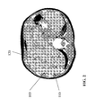
- FIG. 2 a magnetic resonance tomogram of the liver.
- the liver 100 is interspersed with several metastases 110, which are still easily separable from healthy tissue.
- several implants 120 in the form of permanent magnets in puncture technique are implanted into the metastases, which concentrate a tumor-effective medication enclosed in ferromagnetic, resorbable nano drug depots in the target area.
- dissolution of the absorbable depots eg from Fe 3 O 4
- the strong local action of the normally strongly systemically active substances e.g from Fe 3 O 4
- an implant in the form of an implantable magnet 200 is shown, whose permanent magnetic core 210 is coated with a coagulation-promoting drug (eg, coagulation factors, vitamin K or aprotin) 220.
- a coagulation-promoting drug eg, coagulation factors, vitamin K or aprotin
- This coating is surrounded by a bioresorbable protective and sliding layer 230, so that the drug is released only after administration to the target organ.
- the dimensions of the illustrated implantable magnet are e.g. in length less than 3mm and in diameter less than 1mm.
- the preferred material for the magnet is a neodymium compound coated with a biocompatible material.
- the goal of the drug coating is to minimize the risk of bleeding upon implantation in a heavily perfused tumor tissue and to form a necrotic capsule around the implant, thereby providing fixation of the implantable magnet.
- the implantable magnet itself serves to drug concentration in a therapeutic target area by injecting the drugs bound to nanometric magnetic carriers.
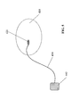
- FIG. 4 a target organ 310 is shown, into which an implant 320 was implanted by means of an applicator 330 by puncture technique.
- the implant is supplied by means of a connected RF generator 340 energy such that a heating of the implant and the surrounding tissue takes place and so a rapid necrosis is promoted.
- connection between applicator and implant is separable (e.g., screw connection or the like), so that subsequently the applicator can be removed (see 350).
- the applicator is optionally designed so that it acts as a biopsy device.
- this consists of an outer biopsy needle and interchangeable inner applicators. These are shaped for biopsy in the usual form of a biopsy device and are used for tissue removal.
- the implant can be positioned at the identical puncture site by means of an applicator, wherein the applicator remains electrically connected to the implant, so that the RF energy can be impressed into the implant.
- the inner applicator is electrically separated from the outer biopsy needle, so that it can serve as a counter electrode for the RF generator.
- the energy is injected into the implant by means of focused ultrasound energy (HIFU: high-intensity focussed ultrasound).
- HIFU high-intensity focussed ultrasound
- the energy converter is designed for converting sound energy into heat energy and preferably has a resonator which is tuned to the frequency of impressed ultrasonic energy.
Landscapes
- Health & Medical Sciences (AREA)
- Life Sciences & Earth Sciences (AREA)
- Public Health (AREA)
- Physics & Mathematics (AREA)
- Biomedical Technology (AREA)
- Heart & Thoracic Surgery (AREA)
- Engineering & Computer Science (AREA)
- Veterinary Medicine (AREA)
- Animal Behavior & Ethology (AREA)
- General Health & Medical Sciences (AREA)
- Molecular Biology (AREA)
- Biophysics (AREA)
- Pathology (AREA)
- Medical Informatics (AREA)
- Surgery (AREA)
- Thermal Sciences (AREA)
- Vascular Medicine (AREA)
- Thermotherapy And Cooling Therapy Devices (AREA)
- Materials For Medical Uses (AREA)
- Media Introduction/Drainage Providing Device (AREA)
- Medicines That Contain Protein Lipid Enzymes And Other Medicines (AREA)
- Prostheses (AREA)
Abstract
Description
- Die Erfindung betrifft ein Implantat mit einem Energiewandler, und zwar speziell ein Mikroimplantat für beispielsweise eine lokale Medikamentenabgabe oder ähnliches.
- Bei derartigen Implantaten besteht grundsätzlich das Problem, diese an einem bestimmten Ort in einem Körper zu fixieren.
- Es sind viele verschiedene "mechanische" Fixationsmethoden für aktive und passive Implantate bekannt.
- Keine der vorbekannten Lösungen bezieht sich jedoch auf die Fixierung von relativ kleinen Implantaten in einem Zielorgan, welches entweder keine festen (z.B. muskulären) Strukturen aufweist oder Blutgefäße zur Fixierung mittels Stent o. ä. aufweisen. Eine Fixierung beispielsweise eines Medikamenten-eluierenden Implantats innerhalb eines Lebertumors oder eines RF-Sensorimplantates im Lungengewebe ist derzeit nicht bekannt.
- Bislang waren derartige Implantate nicht bekannt, so dass auch die Fixierung in o. g. Gewebestrukturen nicht notwendig war. Allerdings werden derartige Anwendungen mit dem Fortschreiten der RF-Technologie und anderen Technologie, wie die Verpackung von Medikamenten in magnetischen Nanostrukturen immer wichtiger und das Problem der Fixierung muss zukünftig gelöst werden.
- Ziel der vorliegenden Erfindung ist es beispielsweise zu ermöglichen, dass mikro- und nanometrisch verpackte Medikamentendepots oder Medikamente zuverlässig, wiederholt und einfach an einem entsprechend definierten Wirkort konzentriert werden können. Im Vordergrund steht dabei eine gut reproduzierbare Anwendung
- Erfindungsgemäß wird dieses Ziel durch ein Implantat mit einem Energiewandler erreicht, bei dem der Energiewandler ausgebildet ist, vorzugsweise berührungsfrei eingeprägte Energie in Wärme zu wandeln, und wobei der Energiewandler in Bezug auf das übrige Implantat derart angeordnet ist, dass infolge der Energiewandlung entstehende Wärme an einer Außenfläche des Implantat wirksam wird.
- Ein solches Implantat erlaubt es, von außen berührungslos Energie einzuprägen, die dann durch den Energiewandler in Wärme umgesetzt wird. Die Wärme wird an wenigstens einer Außenfläche des Implantats wirksam und führt zu einer Gewebekoagulation. Die Gewebekoagulation bewirkt eine Blutgerinnung infolge einer Nekrose des Gewebes, die wiederum zu einer Einkapselung des Implantats und damit zu einer Fixierung im Zielorgan führt.
- Entsprechend ist der Energiewandler so ausgebildet, dass er eine ausreichend hohe Leistung aufnehmen und entsprechend eine ausreichend hohe Wärmeleistung abgeben kann, um eine derartige Gewebekoagulation zu bewirken.
- Zur Unterstützung einer derartigen Einkapselung des Implantats kann das Implantat gemäß einer bevorzugten Ausführungsvariante mit einem gerinnungsfördernden Wirkstoff beschichtet sein, um so die Blutungskomplikation im Zielorgan, beispielsweise stark durchbluteten Tumoren, zu verringern. Dementsprechend kann die Beschichtung als Wirkstoff Gerinnungsfaktoren und insbesondere Vitamin K und/oder Aprotinin enthalten.
- Es entsteht so ein dauerhaft im menschlichen Körper und seinen Organen implantierbares aktives oder passives Implantat, das eine Oberfläche oder eine Oberflächenbeschichtung besitzt, die eine Einkapselung des Implantats in das umliegende Gewebe bewirkt.
- Das Implantat kann beispielsweise ein Permanentmagnet sein oder aus einem magnetisierbaren und entmagnetisierbaren Material bestehen, um auf diese Weise mikro-oder namometrisch verpackte Medikamentendepots an einem gewünschten Wirkort zu konzentrieren. Diese Medikamentendepots bestehen bzw. beinhalten ferromagnetische Trägerstrukturen, die eine Medikament aufnehmen können und über den Blutkreislauf im Körper zirkulieren. Die Freisetzung der Wirkstoffe erfolgt entweder durch eine definierte Elution oder durch Auflösung der biodegradierbaren Trägerstruktur (z.B. Fe3O4) Ist das Implantat aus einem entmagnetisierbaren Material, so kann im Rahmen einer sequenziellen Therapie wahlweise ein Wirkort für die Therapie "hinzu- oder abgeschaltet" werden.
- Außerdem besteht das Implantat vorzugsweise aus einem biodegradierbaren Material, so dass das Implantat im Laufe der Zeit vom Körper abgebaut wird.
- Auch können an dem Implantat Medikamentendepots vorgesehen sein, die Medikamente enthalten können, die im Laufe der Zeit nach der Implantation freigesetzt, d.h. eluiert werden.
- Das Implantat kann auch als aktives Implantat mit einer Medikamentenpumpe oder einem gezielt freizugebenden Medikamentendepot sein.
- Zusätzlich oder alternativ kann das Implantat auch ein aktives oder ein passives Sensorimplantat zum Überwachen eines oder mehrerer physiologischer Parameter sein. In diesem Falle könnte das Implantat beispielsweise ein an sich bekanntes RFID-Implantat sein.
- Zum Erreichen des eingangs genannten Ziels wird auch eine Kombination aus einem Implantat der hierin zuvor beschriebenen Art mit einem Applikator vorgeschlagen, der zum einen zum Einführen des Implantats in den Körper dient und darüber hinaus vorzugsweise auch eine Einkopplung oder Einprägung von Energie in das Implantat ermöglicht. Ein derartiger Applikator wird nur temporär zum Einführen und Fixieren des Implantates genutzt und kann nach der Implantation entfernt werden.
- Zusätzlich oder alternativ kann der Applikator auch ein Biopsiegerät sein, mit dem gleichzeitig eine Gewebeprobe entnommen und das Implantat appliziert werden kann. Gemäß einer bevorzugten Ausführungsvariante ist der Applikator außerdem dazu ausgebildet, über den Applikator Energie in das Implantat einzuprägen, um so eine Gewebefixierung zu bewirken.
- Gemäß einer Variante ist der Energiewandler dazu ausgebildet, über ein elektromagnetisches Wechselfeld eingeprägte elektrische Leistung aufzunehmen. Der Energiewandler enthält in diesem Falle ein elektrisches Heizelement, das die aufgenommene elektrische Leistung in Wärmeleistung wandelt. Zum Aufnehmen von Leistung aus einem elektromagnetischen Wechselfeld besitzt der Wandler vorzugsweise eine Antenne oder ist mit einer Antenne zu verbinden. Die Antenne kann Teil eines Resonators sein, der auf eine Frequenz eines elektromagnetischen Wechselfeldes abgestimmt ist.
- Alternativ hierzu kann der Energiewandler auch eine Spule aufweisen, so dass elektrische Leistung induktiv, d.h. über ein im Wesentlichen magnetisches Feld, einzuprägen ist.
- Gemäß einer weiteren Alternative kann der Energiewandler auch zum Wandeln von Schallenergie in Wärmeenergie ausgebildet sein und dazu einen entsprechenden mechanischen Resonator aufweisen, der auf die Frequenz eingeprägter Ultraschallenergie abgestimmt ist.
- Im Falle eines Implantates, dessen Energiewandler zur Aufnahme von Energie über ein hochfrequentes elektromagnetisches Wechselfeld ausgebildet ist, besitzt der Energiewandler vorzugsweise eine Antenne oder ist mit einer solchen zu verbinden (siehe oben). Die Antenne kann dabei beispielsweise Teil eines Applikators sein (siehe ebenfalls oben) oder ein separates Teil, das beispielsweise aus resorbierbaren Materialien besteht. In diesem Falle könnte die Antenne einen Isolator aus einem degradierbaren Polymer und einen Leiter aus einem degradierbaren Metall, wie beispielsweise Magnesium, enthalten.
- Das Implantat ist vorzugsweise kürzer als 10 cm und damit ausreichend klein, um als MRT-kompatibel zu gelten. Die mit dem Implantat und dessen Energiewandler verbundene Antenne kann dabei länger sein, insbesondere wenn die Antenne - wie zuletzt gesagt - bioresorbierbar ausgeführt ist, so dass das Implantat nach Degradation der Antenne wieder MRT-kompatibel ist. Wie zuvor erwähnt, ist das Implantat vorzugsweise ein sehr kleines Implantat mit einer Masse von weniger als 10 g und besonders bevorzugt weniger als 1 g. Das Volumen des Implantates ist vorzugsweise kleiner als 10 cm3 und besonders bevorzugt kleiner als 1 cm3. Noch kleinere Implantate mit einem Volumen von weniger als 10 mm3 oder besser noch weniger als 1 mm3 sind ganz besonders bevorzugt und eignen sich insbesondere als Medikamententräger für die lokale Medikamentenapplikation.
- Gemäß einer bevorzugten Ausführungsaltemative ist das Implantat mit einer Extraktionshilfe verbunden, die es erlaubt, das Implantat beispielsweise nach erfolgter Medikamentenabgabe oder abgeschlossenem Monitoring wieder zu entfernen. Eine derartige Extraktionshilfe ist dann nicht erforderlich, wenn - wie zuvor dargestellt - das Implantat vollständig aus bioresorbierbarem oder biodegradierbarem Material besteht.
- Vorzugsweise sind das Implantat und sein Energiewandler dazu ausgebildet, eine Hyperthermie-Therapie auszuführen, also eine Therapie, die auf einer Erwärmung des Gewebes über die natürliche Körpertemperatur hinaus beruht, ohne dass es dabei zu einer Koagulation kommt. In diesem Falle können das Implantat und der Energiewandler in vorteilhafter Weise sowohl zur Fixierung des Implantats mittels Gewebekoagulation durch entsprechende Überhitzung des Gewebes dienen, um dann anschließend nach erfolgter Fixierung eine Hyperthermie-Therapie mit dem Implantat durchzuführen. Für den Zweck der Gewebenekrotisierung per Koagulation und die Hyperthermie-Therapie können aber auch unterschiedliche Energiewandler vorgesehen sein, um die jeweiligen Energiewandler besser auf den jeweiligen speziellen Zweck abstimmen zu können.
- Im Folgenden soll nun die Erfindung in Bezug auf die Figuren näher erläutert werden. Von den Figuren zeigt:
- Figur 1:
- ein erfindungsgemäßes Implantat in schematischer Darstellung;
- Figur 2:
- mehrere Implantate in einem Zielorgan;
- Figur 3:
- einen medikamentenbeschichtete, implantierbaren Magnet;
- Figur 4:
- einen Applikator mit Implantat für die die HF-Koagulation; und
- Figur 5:
- ein Implantat mit HF-Antenne
-
Fig. 1 zeigt ein erfindungsgemäßes Implantat 10, das als Mikroimplantat mit einem wärmeleitenden Gehäuse 20 ausgebildet ist und einen Energiewandler 30 aufweist, der seinerseits wieder einen Energieempfänger 40 aufweist oder mit diesem verbunden ist. Der Energieempfänger 40 kann ein mechanischer Resonator sein oder eine Antenne zum Empfang hochfrequenter elektromagnetischer Strahlung oder auch einer Spule zur Induktion von Leistung auf magnetischem Wege. Die über ein hochfrequentes elektromagnetisches Wechselfeld über eine Antenne empfangene Leistung oder die über eine Spule auf dem Wege der Induktion empfangene Leistung steht im Ergebnis als elektrische Leistung zur Verfügung. In diesem Falle enthält der Energiewandler 30 vorzugsweise ein elektrisches Heizelement, das die elektrische Leistung in Wärme wandelt. Ein derartiges elektrisches Heizelement könnte beispielsweise nach Art eines Ohm'schen Widerstandes aufgebaut sein. - Der Energieempfänger 40 ist mit dem eigentlichen Energiewandler 30 derart verbunden, dass über den Energieempfänger 40 empfangene Energie von dem Energiewandler 30 in Wärme zu wandeln ist. Dabei ist der Energiewandler 30 so mit dem Gehäuse 20 des Implantats 10 verbunden, dass die infolge der Energiewandlung entstehende Wärme über das Gehäuse 20 des Implantats 10 an umliegendes Gewebe abgegeben wird.
- Der Energiewandler 30 und der Energieempfänger 40 sowie auch das Implantat 10 selbst sind so ausgebildet, dass das Implantat 10 über den Energieempfänger 40 genügend Leistung aufnehmen kann und der Energiewandler diese Leistung in Wärme wandelt, die ausreicht, um in der unmittelbaren Umgebung des Implantats 10 eine Gewebekoagulation und damit im Ergebnis eine Gewebenekrose zu bewirken, die zu einer Einkapselung des Implantats 10 und damit zu einer Fixierung des Implantats 10 führt.
- Das in
Fig. 1 abgebildete Implantat 10 ist in der dargestellten bevorzugten Ausführungsvariante eine Medikamentenbeschichtung 50. - Bei dieser Medikamentenbeschichtung 50 kann es sich um einen therapeutischen Wirkstoff handeln, beispielsweise zur Tumorbekämpfung. Zusätzlich oder alternativ kann die Medikamentenbeschichtung 50 jedoch auch einen Gerinnungsfaktor und insbesondere Vitamin K und/oder Aprolinin enthalten, die die Blutgerinnung fördern und damit einerseits Blutungen im Tumorgewebe hemmen und so einer Verschleppung von Tumorzellen entgegenwirken und andererseits auch die Fixierung des Implantats fördern.
- In diesem Zusammenhang ist darauf hinzuweisen, dass die Fixation des Implantats durch Einkapselung infolge Gewebekoagulation auch den Vorteil mit sich bringt, dass hierdurch ebenfalls eine Verschleppung von Tumorzellen vermindert wird.
- Wie eingangs bereits erwähnt, kann das Implantat 10 darüber hinaus gezielte Medikamentendepots enthalten oder auch als aktives oder passives Sensorimplantat, beispielsweise als RFID-Implantat ausgebildet sein. Alle Bestandteile des Implantats 10 können aus biodegradierbarem oder bioresorbierbarem Material bestehen und beispielsweise biodegradierbare Metalle, wie Magnesium, enthalten. Mögliche Sensoren für ein solches Implantat sind Sensoren zur lokalen Druckmessung, potentiometrische pH-Wert-Sensorsen oder Temperatursensoren.
- Wie nachfolgend in Bezug auf
Fig. 3 noch näher erläutert, kann das Implantat 10 auch magnetisch sein, so dass ferromagnetische Medikamentendepots magnetisch an das Implantat 10 gekoppelt sein können bzw. dieses injizierte magnetische, nanometrisch verpackte Medikamentendepots anziehen kann. - In der
Figur 2 ist ein Magnet-Resonanz- Tomogram der Leber gezeigt. In diesem Fall ist die Leber 100 mit mehreren Metastasen 110 durchsetzt, die vom gesunden Gewebe noch gut abtrennbar sind. Zur Konzentration der Tumormedikation sind in die Metastasen mehrere Implantate 120 in Form von Permanentmagneten in Punktionstechnik implantiert, die eine tumorwirksame, in ferromagnetischen, resorbierbaren Nano-Medikamentendepots eingeschlossene Medikation im Zielgebiet konzentrieren. Nach Auflösung der resorbierbaren Depots (z.B. aus Fe3O4) erfolgt dann die stark lokale Wirkung der normalerweise stark systemisch wirksamen Substanzen. - In der
Figur 3 ist ein Implantat in Form eines implantierbaren Magneten 200 dargestellt, dessen permanentmagnetischer Kern 210 mit einem gerinnungsfördernden Medikament (z.B. Gerinnungsfaktoren, Vitamin K oder Aprotin) 220 beschichtet ist. Diese Beschichtung wiederum ist von einer bioresorbierbaren Schutz- und Gleitschicht 230 umgeben, so dass der medikamentöse Wirkstoff erst nach Applikation in das Zielorgan abgegeben wird. - Die Dimensionen des dargestellten implantierbaren Magneten betragen z.B. hinsichtlich der Länge weniger als 3mm und hinsichtlich des Durchmessers weniger als 1mm. Das bevorzugte Material für den Magneten ist eine Neodym-Verbindung, beschichtet mit einem biokompatiblen Material.
- Das Ziel der medikamentösen Beschichtung besteht darin dass das Blutungsrisiko bei Implantation in einem stark durchbluteten Tumorgewebe minimiert wird und eine nekrotische Kapsel um das Implantat gebildet wird, so dass damit eine Fixation des implantierbaren Magneten stattfindet. Der implantierbare Magnet selbst dient der Medikamentenkonzentration in einem therapeutischen Zielgebiet, indem die Medikamente, gebunden an nanometrische magnetische Trägersubstanzen injiziert werden.
- In der
Figur 4 ist ein Zielorgan 310 dargestellt, in das ein Implantat 320 mittels eines Applikators 330 durch Punktionstechnik implantiert wurde. Zur Fixation des Implantates wird dem Implantat mittels eines angeschlossenen HF-Generators 340 Energie derart zugeführt, dass eine Erwärmung des Implantates und des umgebenden Gewebes stattfindet und so eine schnelle Nekrotisierung gefördert wird. - Die Verbindung zwischen Applikator und Implantat ist trennbar (z.B. Schraubverbindung o. ä.), so dass anschließend der Applikator entfernt werden kann (siehe 350).
- Der Applikator ist dabei optional so gestaltet, dass dieser als Biopsiegerät fungiert. In dieser Ausführung besteht dieser aus einer äußeren Biopsienadel und austauschbaren Innenapplikatoren. Diese sind für die Biopsie in der gängigen Form eines Biopsiegerätes geformt und dienen der Gewebeentnahme. Nach der Biopsie kann an die identische Punktionsstelle das Implantat mittels eines Applikators positioniert werden, wobei der Applikator elektrisch mit dem Implantat verbunden bleibt, so dass die HF-Energie in das Implantat eingeprägt werden kann. Der innere Applikator ist elektrisch von der äußeren Biopsienadel getrennt, so dass die als Gegenelektrode für den HF-Generator dienen kann.
- In einer alternativen Ausführung erfolgt die Energieeinprägung in das Implantat mittels fokusierter Ultraschallenergie (HIFU: High-intensity focussed ultrasound). In diesem Fall ist der Energiewandler zum Wandeln von Schallenergie in Wärmeenergie ausgebildet und weist vorzugsweise einen Resonator auf, der auf die Frequenz eingeprägter Ultraschallenergie abgestimmt ist.
- Bei dem in
Figur 5 dargestellten Implantat 420 kann es sich z.B. handeln um: - eine implantierbare Medikamentenpumpe mit eigener Energieversorgung oder
- eine implantierbare Medikamentenpumpe zur Bedarfsmedikation ohne eigene Energieversorgung, gesteuert durch externe Energieeinkopplung oder
- ein Implantat zur Hyperthermietherapie, dass eine gezielte Erwärmung von Gewebe mittels Umwandlung externer eingeprägter Energie bewirkt, wobei hier bevorzugt eine Energieumwandlung eines MRT-Systems genutzt werden kann und die Therapiesteuerung dabei durch unterschiedliche MRT-Frequenzen oder steuerbare Demodulatoren im Hyperthermieimplantat realisiert wird oder
- ein Sensorimplantat mit eigener Energieversorgung und Telemetriefunktion (z.B. Glucose oder pH-Sensor) oder
- ein Sensorimplantat ohne eigene Energieversorgung mit externer Abfragefunktion (z.B. mittels Ultraschall) oder
- ein implantierbares Medikamentendepot mit einer festen oder steuerbaren Elutionsrate.
- Des Weiteren sind in der
Figur 5 dargestellt: - das Zielorgan 410,
- eine Antennenleitung zur Einprägung von HF-Energie, kann gleichzeitig als Extraktionshilfe dienen 430 und
- eine flächige Gegenelektrode für die HF-Koagulation, Fläche ist deutlich größer als die Implantatsoberfläche, so dass eine relevante Erwärmung nur am Implantat erfolgt 440.
Claims (16)
- Implantat mit einem Energiewandler, dadurch gekennzeichnet, dass der Energiewandler ausgebildet ist eingeprägte Energie in Wärme zu wandeln, wobei der Energiewandler angeordnet ist, dass infolge der Energiewandlung entstehende Wärme an einer Außenfläche des Implantats wirksam wird.
- Implantat nach Anspruch 1, dadurch gekennzeichnet, dass der Energiewandler eine elektrisches Heizelement ist.
- Implantat nach Anspruch 2, dadurch gekennzeichnet, dass der Energiewandler eine Antenne aufweist oder mit einer Antenne verbunden ist, die zum Empfang mittels eines elektromagnetischen Wechselfeldes eingeprägter elektrischer Leistung ausgebildet und mit dem elektrischen Heizelement derart verbunden ist, dass empfangene elektrische Leistung in dem elektrischen Heizelement in Wärme gewandelt wird.
- Implantat nach Anspruch 1, dadurch gekennzeichnet, dass der Energiewandler zum Wandeln von Schallenergie in Wärmeenergie ausgebildet ist.
- Implantat nach Anspruch 4, dadurch gekennzeichnet, dass der Energiewandler einen Resonator aufweist, der auf die Frequenz eingeprägter Ultraschallenergie abgestimmt ist.
- Implantat nach einem der Ansprüche 1 bis 5, dadurch gekennzeichnet, dass das Implantat mit einem gerinnungsfördernden Wirkstoff beschichtet ist.
- Implantat nach einem der Ansprüche 1 bis 6, dadurch gekennzeichnet, dass das Implantat ist ein Permanentmagnet ist.
- Implantat nach einem der Ansprüche 1 bis 7, dadurch gekennzeichnet, dass das Implantat ein magnetisierbares und entmagnetisierbares Material zur magnetischen Medikamentenadhäsion enthält.
- Implantat nach einem der Ansprüche 1 bis 6, dadurch gekennzeichnet, dass das Implantat aus biodegradierbaren Material besteht.
- Implantat nach einem der Ansprüche 1 bis 9, dadurch gekennzeichnet, dass das Implantat Medikamentendepots zur Medikamentenfreisetzung besitzt.
- Implantat nach einem der Ansprüche 1 bis 10, dadurch gekennzeichnet, dass das Implantat mit einem Applikator lösbar verbunden ist, über den eine Einkopplung von HF-Energie möglich ist, die zu einer Koagulation des Implantates führt.
- Implantat nach Anspruch 11, dadurch gekennzeichnet, dass der Applikator ein Biopsiegerät ist, das derart ausgebildet ist, dass gleichzeitig eine Gewebeprobe entnommen und das Implantat platziert werden kann.
- Implantat nach einem der Ansprüche 2 bis 12, dadurch gekennzeichnet, dass die Antenne aus resorbierbaren Materialien besteht.
- Implantat nach einem der Ansprüche 1 bis 6, dadurch gekennzeichnet, dass das zu fixierende Implantat eine Medikamentenpumpe oder ein Medikamentendepot ist.
- Implantat nach einem der Ansprüche 1 bis 6, dadurch gekennzeichnet, dass das zu fixierende Implantat ein aktives oder aber ein passives Sensorimplantat zur Überwachung eines oder mehrerer physiologischer Parameter ist.
- Implantat nach einem der Ansprüche 1 bis 6, dadurch gekennzeichnet, dass das zu fixierende Implantat ist ein Energiewandler für die Hyperthermietherapie ist, wobei entweder der gleiche Mechanismus für die Energiewandlung für die Implantatsfixierung und die Hyperthermie genutzt wird oder aber unterschiedliche Mechanismen für Fixation und Hyperthermie eingesetzt werden.
Applications Claiming Priority (1)
| Application Number | Priority Date | Filing Date | Title |
|---|---|---|---|
| US32336110P | 2010-04-13 | 2010-04-13 |
Publications (2)
| Publication Number | Publication Date |
|---|---|
| EP2377574A2 true EP2377574A2 (de) | 2011-10-19 |
| EP2377574A3 EP2377574A3 (de) | 2011-11-30 |
Family
ID=44206723
Family Applications (1)
| Application Number | Title | Priority Date | Filing Date |
|---|---|---|---|
| EP11159331A Withdrawn EP2377574A3 (de) | 2010-04-13 | 2011-03-23 | Implantat und Applikator |
Country Status (2)
| Country | Link |
|---|---|
| US (1) | US9462962B2 (de) |
| EP (1) | EP2377574A3 (de) |
Families Citing this family (9)
| Publication number | Priority date | Publication date | Assignee | Title |
|---|---|---|---|---|
| US10852069B2 (en) | 2010-05-04 | 2020-12-01 | Fractal Heatsink Technologies, LLC | System and method for maintaining efficiency of a fractal heat sink |
| US10173069B2 (en) * | 2012-01-26 | 2019-01-08 | Medtronic, Inc. | Medical device fixation |
| CN105453198A (zh) * | 2013-08-08 | 2016-03-30 | 克拉鲁斯科技私人有限公司 | 仿生肌肉 |
| CN105650718A (zh) * | 2016-02-01 | 2016-06-08 | 唐宇前 | 一种电磁式加热取暖器 |
| EP3727577B1 (de) | 2017-12-19 | 2024-01-24 | Cardiac Pacemakers, Inc. | Gehäuse für implantierbares medizinprodukt |
| JP2021529055A (ja) * | 2018-06-26 | 2021-10-28 | オーストラリアン インスティテュート オブ ロボティック オーソピーディクス プロプライエタリー リミテッド | インプラント適合度分析 |
| US12678067B1 (en) | 2019-03-20 | 2026-07-14 | Biological Art Group, Inc. | Telemetry implants |
| EP3996617B1 (de) * | 2019-07-10 | 2025-09-03 | David Cohen | Vorrichtung zur behandlung von tumoren mit einem behandlungsobjekt und speisung des behandlungsobjekts |
| WO2021034784A1 (en) | 2019-08-16 | 2021-02-25 | Poltorak Technologies, LLC | Device and method for medical diagnostics |
Family Cites Families (26)
| Publication number | Priority date | Publication date | Assignee | Title |
|---|---|---|---|---|
| US3731681A (en) * | 1970-05-18 | 1973-05-08 | Univ Minnesota | Implantable indusion pump |
| US3653385A (en) * | 1970-10-20 | 1972-04-04 | Charles Burton | Production of focal brain lesions by inductive heating |
| US5197649A (en) * | 1991-10-29 | 1993-03-30 | The Trustees Of Columbia University In The City Of New York | Gastrointestinal endoscoptic stapler |
| DE69225043T2 (de) * | 1991-11-20 | 1998-09-03 | Matsuki Hidetoshi | Injizierbares Pulver zur Behandlung von Krebs |
| US5843028A (en) * | 1992-05-11 | 1998-12-01 | Medical Innovations Corporation | Multi-lumen endoscopic catheter |
| US6540693B2 (en) * | 1998-03-03 | 2003-04-01 | Senorx, Inc. | Methods and apparatus for securing medical instruments to desired locations in a patients body |
| US7346391B1 (en) | 1999-10-12 | 2008-03-18 | Flint Hills Scientific Llc | Cerebral or organ interface system |
| GB9930000D0 (en) * | 1999-12-21 | 2000-02-09 | Phaeton Research Ltd | An ingestible device |
| US7039453B2 (en) * | 2000-02-08 | 2006-05-02 | Tarun Mullick | Miniature ingestible capsule |
| US6689125B1 (en) * | 2000-04-04 | 2004-02-10 | Spinalabs, Llc | Devices and methods for the treatment of spinal disorders |
| US20050278014A9 (en) * | 2001-03-07 | 2005-12-15 | Wolfgang Daum | Stent and method for drug delivery from stents |
| US7751903B2 (en) * | 2002-04-15 | 2010-07-06 | Greatbatch Ltd. | Frequency selective passive component networks for implantable leads of active implantable medical devices utilizing an energy dissipating surface |
| ATE547976T1 (de) * | 2002-12-26 | 2012-03-15 | Given Imaging Ltd | Immobilisierbare in-vivo messvorrichtung |
| US20060041182A1 (en) * | 2003-04-16 | 2006-02-23 | Forbes Zachary G | Magnetically-controllable delivery system for therapeutic agents |
| US20060025713A1 (en) * | 2003-05-12 | 2006-02-02 | Alex Rosengart | Magnetic particle-based therapy |
| US20070196281A1 (en) | 2003-12-31 | 2007-08-23 | Sungho Jin | Method and articles for remote magnetically induced treatment of cancer and other diseases, and method for operating such article |
| US7976520B2 (en) | 2004-01-12 | 2011-07-12 | Nulens Ltd. | Eye wall anchored fixtures |
| US7654985B2 (en) * | 2004-03-30 | 2010-02-02 | Given Imaging Ltd. | Controlled detachment of intra-luminal medical device |
| US8425539B2 (en) | 2004-04-12 | 2013-04-23 | Xlumena, Inc. | Luminal structure anchoring devices and methods |
| WO2005110395A1 (en) * | 2004-05-19 | 2005-11-24 | University Of South Carolina | System and device for magnetic drug targeting with magnetic drug carrier particles |
| US7410497B2 (en) | 2004-12-14 | 2008-08-12 | Boston Scientific Scimed, Inc. | Stimulation of cell growth at implant surfaces |
| CN1772303A (zh) * | 2005-10-25 | 2006-05-17 | 朱宏 | 恶性肿瘤磁热疗用纳米磁粉-抗体靶向药物 |
| US20070191816A1 (en) * | 2006-02-13 | 2007-08-16 | Boston Scientific Scimed, Inc. | Radio frequency induced drug elution |
| CA2647994A1 (en) * | 2006-03-31 | 2007-11-08 | Peak Surgical, Inc. | Devices and methods for tissue welding |
| US20080103584A1 (en) * | 2006-10-25 | 2008-05-01 | Biosensors International Group | Temporal Intraluminal Stent, Methods of Making and Using |
| US8322346B2 (en) * | 2007-06-28 | 2012-12-04 | Integrated Sensing Systems, Inc. | Minimally-invasive procedure for monitoring a physiological parameter within an internal organ |
-
2011
- 2011-03-23 EP EP11159331A patent/EP2377574A3/de not_active Withdrawn
- 2011-03-23 US US13/070,401 patent/US9462962B2/en not_active Expired - Fee Related
Non-Patent Citations (1)
| Title |
|---|
| None |
Also Published As
| Publication number | Publication date |
|---|---|
| US9462962B2 (en) | 2016-10-11 |
| US20110251516A1 (en) | 2011-10-13 |
| EP2377574A3 (de) | 2011-11-30 |
Similar Documents
| Publication | Publication Date | Title |
|---|---|---|
| EP1847227B1 (de) | Elektrisches Marknagelsystem | |
| DE69929528T2 (de) | Vorrichtung zum einführen eines medikaments in einer gewebsmembran, implantationsvorrichtung und injektionsvorrichtung | |
| EP2130566B1 (de) | Langgestrecktes Implantat mit externer Energieeinkopplung | |
| EP2105163B1 (de) | Magnetwechselfeld-Applikationsvorrichtung zur Aufheizung von magnetischen oder magnetisierbaren Substanzen in biologischem Gewebe | |
| US9462962B2 (en) | Implant and applicator | |
| DE60124948T2 (de) | Leitungen für die gerichtete Hirnstimulation und-aufzeichnung | |
| DE2314573A1 (de) | Geraet zur foerderung von heilungsprozessen | |
| DE2116869C2 (en) | Bone and biological tissue growth promotion appts. - uses flat coil for application of LF current from generator | |
| EP2074958A2 (de) | Kontakvorrichtung für die Osteosynthese | |
| WO2001007111A2 (en) | Magnetic toroids for the stimulation of biological tissue | |
| DE102010022926A1 (de) | Mikrokapsel zur lokalen Behandlung eines Tumors, Verfahren zur Positionierung eines magnetische Nanopartikel an einen Zielort führenden und/oder an dem Zielort haltenden magnetischen Gradientenfeldes und Vorrichtung zur Positionierung eines magnetischen Gradientenfeldes | |
| US20100036465A1 (en) | Insertion tools and methods for an electrical stimulation implant | |
| EP4051092B1 (de) | Lichtapplikator | |
| CN1708260A (zh) | 用于微创外科中组织热疗的、具有侧向效应的组织间隙微波天线 | |
| US20100168829A1 (en) | System for implanting, activating, and operating an implantable battery | |
| EP2184082A1 (de) | Implantierbare Leitung | |
| EP2421475B1 (de) | Elektrische hüftgelenkprothese | |
| EP2014264A1 (de) | Implantat und System aus einem Implantat und einer Anregungsvorrichtung | |
| DE2552523A1 (de) | Elektrische vorrichtung zur regeneration und zum aufbau von kalkhaltigen geweben und knorpel | |
| EP2347407B1 (de) | Impulswellengenerator | |
| DE19600744A1 (de) | Magnetische Substanz zur lokalen hyperthermischen Behandlung vorwiegend kleiner Tumore | |
| WO2009010303A2 (de) | System zum verabreichen von wirkstoffen an einem organismus, einrichtungen zur verwendung in einem solchen system sowie verfahren zur herstellung derartiger einrichtungen | |
| EP2512589B1 (de) | Vorrichtung zum verabreichen von arzneimitteln und zum beeinflussen von arzneimittelwirkungen | |
| DE102010015730B4 (de) | MR-sicheres und -kompatibles sowie multifunktionales Katheter-Führungsdrahtsystem | |
| EP2465570B1 (de) | Implantierbares Gerät |
Legal Events
| Date | Code | Title | Description |
|---|---|---|---|
| AK | Designated contracting states |
Kind code of ref document: A2 Designated state(s): AL AT BE BG CH CY CZ DE DK EE ES FI FR GB GR HR HU IE IS IT LI LT LU LV MC MK MT NL NO PL PT RO RS SE SI SK SM TR |
|
| AX | Request for extension of the european patent |
Extension state: BA ME |
|
| PUAL | Search report despatched |
Free format text: ORIGINAL CODE: 0009013 |
|
| PUAI | Public reference made under article 153(3) epc to a published international application that has entered the european phase |
Free format text: ORIGINAL CODE: 0009012 |
|
| AK | Designated contracting states |
Kind code of ref document: A3 Designated state(s): AL AT BE BG CH CY CZ DE DK EE ES FI FR GB GR HR HU IE IS IT LI LT LU LV MC MK MT NL NO PL PT RO RS SE SI SK SM TR |
|
| AX | Request for extension of the european patent |
Extension state: BA ME |
|
| RIC1 | Information provided on ipc code assigned before grant |
Ipc: A61K 9/00 20060101ALN20111027BHEP Ipc: H02J 17/00 20060101ALN20111027BHEP Ipc: A61B 5/07 20060101ALN20111027BHEP Ipc: A61K 41/00 20060101ALI20111027BHEP Ipc: A61F 7/12 20060101ALI20111027BHEP Ipc: A61N 1/40 20060101AFI20111027BHEP |
|
| 17P | Request for examination filed |
Effective date: 20120523 |
|
| 17Q | First examination report despatched |
Effective date: 20150127 |
|
| STAA | Information on the status of an ep patent application or granted ep patent |
Free format text: STATUS: THE APPLICATION IS DEEMED TO BE WITHDRAWN |
|
| 18D | Application deemed to be withdrawn |
Effective date: 20150609 |