EP2376356B1 - Sheet deceleration apparatus, method for decelerating a sheet, and a sheet stacking apparatus - Google Patents
Sheet deceleration apparatus, method for decelerating a sheet, and a sheet stacking apparatus Download PDFInfo
- Publication number
- EP2376356B1 EP2376356B1 EP10700079.6A EP10700079A EP2376356B1 EP 2376356 B1 EP2376356 B1 EP 2376356B1 EP 10700079 A EP10700079 A EP 10700079A EP 2376356 B1 EP2376356 B1 EP 2376356B1
- Authority
- EP
- European Patent Office
- Prior art keywords
- sheet
- rollers
- conveyor
- sheets
- speed
- Prior art date
- Legal status (The legal status is an assumption and is not a legal conclusion. Google has not performed a legal analysis and makes no representation as to the accuracy of the status listed.)
- Active
Links
Images


Classifications
-
- B—PERFORMING OPERATIONS; TRANSPORTING
- B65—CONVEYING; PACKING; STORING; HANDLING THIN OR FILAMENTARY MATERIAL
- B65H—HANDLING THIN OR FILAMENTARY MATERIAL, e.g. SHEETS, WEBS, CABLES
- B65H29/00—Delivering or advancing articles from machines; Advancing articles to or into piles
- B65H29/68—Reducing the speed of articles as they advance
-
- B—PERFORMING OPERATIONS; TRANSPORTING
- B65—CONVEYING; PACKING; STORING; HANDLING THIN OR FILAMENTARY MATERIAL
- B65H—HANDLING THIN OR FILAMENTARY MATERIAL, e.g. SHEETS, WEBS, CABLES
- B65H29/00—Delivering or advancing articles from machines; Advancing articles to or into piles
- B65H29/26—Delivering or advancing articles from machines; Advancing articles to or into piles by dropping the articles
- B65H29/32—Delivering or advancing articles from machines; Advancing articles to or into piles by dropping the articles from pneumatic, e.g. suction, carriers
-
- B—PERFORMING OPERATIONS; TRANSPORTING
- B65—CONVEYING; PACKING; STORING; HANDLING THIN OR FILAMENTARY MATERIAL
- B65G—TRANSPORT OR STORAGE DEVICES, e.g. CONVEYORS FOR LOADING OR TIPPING, SHOP CONVEYOR SYSTEMS OR PNEUMATIC TUBE CONVEYORS
- B65G57/00—Stacking of articles
- B65G57/02—Stacking of articles by adding to the top of the stack
- B65G57/03—Stacking of articles by adding to the top of the stack from above
- B65G57/04—Stacking of articles by adding to the top of the stack from above by suction or magnetic devices
-
- B—PERFORMING OPERATIONS; TRANSPORTING
- B65—CONVEYING; PACKING; STORING; HANDLING THIN OR FILAMENTARY MATERIAL
- B65H—HANDLING THIN OR FILAMENTARY MATERIAL, e.g. SHEETS, WEBS, CABLES
- B65H2301/00—Handling processes for sheets or webs
- B65H2301/40—Type of handling process
- B65H2301/42—Piling, depiling, handling piles
- B65H2301/421—Forming a pile
- B65H2301/4217—Forming multiple piles
- B65H2301/42172—Forming multiple piles simultaneously
-
- B—PERFORMING OPERATIONS; TRANSPORTING
- B65—CONVEYING; PACKING; STORING; HANDLING THIN OR FILAMENTARY MATERIAL
- B65H—HANDLING THIN OR FILAMENTARY MATERIAL, e.g. SHEETS, WEBS, CABLES
- B65H2404/00—Parts for transporting or guiding the handled material
- B65H2404/10—Rollers
- B65H2404/14—Roller pairs
- B65H2404/144—Roller pairs with relative movement of the rollers to / from each other
- B65H2404/1441—Roller pairs with relative movement of the rollers to / from each other involving controlled actuator
-
- B—PERFORMING OPERATIONS; TRANSPORTING
- B65—CONVEYING; PACKING; STORING; HANDLING THIN OR FILAMENTARY MATERIAL
- B65H—HANDLING THIN OR FILAMENTARY MATERIAL, e.g. SHEETS, WEBS, CABLES
- B65H2404/00—Parts for transporting or guiding the handled material
- B65H2404/10—Rollers
- B65H2404/15—Roller assembly, particular roller arrangement
- B65H2404/152—Arrangement of roller on a movable frame
- B65H2404/1521—Arrangement of roller on a movable frame rotating, pivoting or oscillating around an axis, e.g. parallel to the roller axis
-
- B—PERFORMING OPERATIONS; TRANSPORTING
- B65—CONVEYING; PACKING; STORING; HANDLING THIN OR FILAMENTARY MATERIAL
- B65H—HANDLING THIN OR FILAMENTARY MATERIAL, e.g. SHEETS, WEBS, CABLES
- B65H2404/00—Parts for transporting or guiding the handled material
- B65H2404/60—Other elements in face contact with handled material
- B65H2404/64—Other elements in face contact with handled material reciprocating perpendicularly to face of material, e.g. pushing means
-
- B—PERFORMING OPERATIONS; TRANSPORTING
- B65—CONVEYING; PACKING; STORING; HANDLING THIN OR FILAMENTARY MATERIAL
- B65H—HANDLING THIN OR FILAMENTARY MATERIAL, e.g. SHEETS, WEBS, CABLES
- B65H2406/00—Means using fluid
- B65H2406/30—Suction means
- B65H2406/32—Suction belts
- B65H2406/323—Overhead suction belt, i.e. holding material against gravity
-
- B—PERFORMING OPERATIONS; TRANSPORTING
- B65—CONVEYING; PACKING; STORING; HANDLING THIN OR FILAMENTARY MATERIAL
- B65H—HANDLING THIN OR FILAMENTARY MATERIAL, e.g. SHEETS, WEBS, CABLES
- B65H2701/00—Handled material; Storage means
- B65H2701/10—Handled articles or webs
- B65H2701/13—Parts concerned of the handled material
- B65H2701/131—Edges
- B65H2701/1313—Edges trailing edge
-
- B—PERFORMING OPERATIONS; TRANSPORTING
- B65—CONVEYING; PACKING; STORING; HANDLING THIN OR FILAMENTARY MATERIAL
- B65H—HANDLING THIN OR FILAMENTARY MATERIAL, e.g. SHEETS, WEBS, CABLES
- B65H2701/00—Handled material; Storage means
- B65H2701/10—Handled articles or webs
- B65H2701/17—Nature of material
- B65H2701/176—Cardboard
- B65H2701/1762—Corrugated
-
- Y—GENERAL TAGGING OF NEW TECHNOLOGICAL DEVELOPMENTS; GENERAL TAGGING OF CROSS-SECTIONAL TECHNOLOGIES SPANNING OVER SEVERAL SECTIONS OF THE IPC; TECHNICAL SUBJECTS COVERED BY FORMER USPC CROSS-REFERENCE ART COLLECTIONS [XRACs] AND DIGESTS
- Y10—TECHNICAL SUBJECTS COVERED BY FORMER USPC
- Y10S—TECHNICAL SUBJECTS COVERED BY FORMER USPC CROSS-REFERENCE ART COLLECTIONS [XRACs] AND DIGESTS
- Y10S271/00—Sheet feeding or delivering
- Y10S271/90—Stripper
Definitions
- the present disclosure relates generally to a sheet deceleration apparatus and method and more specifically to a sheet deceleration apparatus and method for use in controlling the speed of a sheet of corrugated board or other sheet material as it leaves the entry or line conveyor and enters a stacking hopper.
- Sheets of corrugated board, paperboard, fiberboard or other sheet material are conventionally conveyed to a stacking hopper on an entry or line conveyor, see e.g. DE 198 17 064 A1 or DE 23 43 678 A1 .
- the sheets are overlapped or shingled, while in other cases, gaps in the direction of movement are provided between adjacent sheets. Because many of the sheets have flaps or other protrusions at their leading edges, overlapped or shingled sheets are often not desirable.
- the sheets are projected off the end of the entry conveyor and over a stacking hopper.
- the stacking hopper includes a generally vertical backstop and a forwardly positioned back tamper to define a bin or area to receive the sheets in stacked form.
- the capacity of a particular sheet stacking apparatus is determined by the number of sheets that can be stacked per unit of time. In general, this is directly related to the speed of the entry conveyor. The greater the speed of the entry conveyor, the greater the number of sheets that can be stacked in a unit of time, and thus the greater the stacking capacity of the sheet stacking apparatus. As the speed of the entry conveyor is increased, however, the sheets are projected over the stacking hopper and against the backstop at an increased speed. At elevated speeds beyond a certain speed (usually about 500 feet per minute for certain sheets), the projection against the backstop results in the sheet bouncing back toward the entry conveyor and/or possible damage to protruding tabs or flaps on the leading edge of the sheet. Accordingly, without deceleration means, a sheet stacker has a certain maximum operational speed.
- the prior art includes various deceleration apparatus which function to decelerate or slow down the speed of the sheets in this region.
- One such prior art machine utilizes a set or pair of spatially fixed rollers at the end of the entry conveyor and prior to the stacking hopper.
- the nip rollers are positioned on opposite sides of the sheet and are designed to run or be driven at the entry conveyor line speed for most of the length of the sheet. As the trailing edge of the sheet approaches these rollers, they are decelerated to a desired lower speed to slow the sheet.
- rollers After the sheet has passed, the rollers are accelerated back to line speed before the next sheet arrives.
- a limitation of this apparatus includes the physical limitations of ramping the rollers up to about 1,000 feet per minute or more and then back down to about 500 feet per minute or less at least three times per second.
- a further limitation or disadvantage includes machine wear and tear associated with this repeated high speed acceleration and deceleration.
- a further deceleration apparatus utilizes an overhead vacuum to transport the sheet into the hopper area. This machine ramps the speed of the vacuum conveyors down to zero, kicks off the end sheet over the hopper, and then ramps back up to line speed. Although this machine is acceptable at lower speeds, it is anticipated that it would have drive problems at higher speeds.
- a goods holding unit having a combined transport storage unit for supplying the goods to the stacking places is disclosed.
- the unit by means of a controller, is movable down from a transport speed (V1) to a storage speed (V0) and with or after reaching the storage speed, the delivery of the respective goods result.
- a sheet stacker in EP0173959 , includes a suction conveyor disposed upwardly of a sheet-stacking table and has a lower sheet-attracting surface for transferring the sheets supplied from a sheet manufacturing machine, a sheet stopper for stopping the advancing movement of the sheets transferred by said suction conveyor, and a sheet separator operable in timed relation to the supply of the sheets from the previous processing station for separating the sheets successively from said suction conveyor so as to fall onto the sheet-stacking table.
- the present disclosure is directed to a sheet deceleration apparatus and method which has particular application for use in a sheet stacking apparatus for stacking sheets of corrugated board, paperboard, fiberboard, or other sheet material from an entry or line conveyor or other delivery means.
- the present disclosure relates to a sheet deceleration apparatus for reducing the speed of a sheet of material moving along a travel path at a first speed.
- the deceleration apparatus includes a first rotatable roller, being rotatable about a first axis, and positioned on one side of the travel path.
- a second rotatable roller being rotatable about a second axis is provided on the other side of the travel path and spaced from the first roller so that the sheet of material can pass between the first and second rollers.
- At least one of the rollers is moveable relative to the other to nip the sheet between the first and second rollers to reduce the travel speed of the sheet.
- a vacuum conveyor is further provided along the travel path subsequent the first and second rollers to control delivery of the sheet to a stacking hopper.
- a third rotatable roller, or similar apparatus, may be included in some embodiments, for pushing the sheet of material away from the vacuum conveyor at the appropriate time.
- a method aspect of the present disclosure includes delivering a sheet of material between first and second rollers, rotatable on first and second axes, respectively, delivering the sheet of material to a vacuum conveyor running at a continuous line speed, and driving at least one of the rollers toward the other to nip the sheet of material between the rollers to reduce the speed of the sheet.
- the present disclosure relates to a sheet stacking apparatus having an entry conveyor, a stacking hopper, a sheet deceleration apparatus, and an exit conveyor.
- the entry conveyor delivers sheets of material along a travel path toward a discharge end of the entry conveyor.
- the stacking hopper is positioned downstream from the entry conveyor.
- the sheet deceleration apparatus is positioned between the discharge end of the entry conveyor and the stacking hopper.
- the sheet deceleration apparatus reduces the travel speed of the sheets of material prior to delivery to the stacking hopper.
- the exit conveyor is positioned at least partially downstream of the sheet deceleration apparatus and controls delivery of the sheets of material to the stacking hopper.
- the exit conveyor comprises a vacuum, or vacuum conveyor.
- the deceleration apparatus and method in accordance with the present disclosure may be used with a sheet stacking machine of the type having an entry conveyor or other sheet delivery means and a stacking hopper.
- the deceleration apparatus and method and the sheet stacking machine are shown and described with reference to Figures 1-10 .
- the sheet stacking machine of one embodiment may include an entry conveyor 10 and a stacking hopper 11.
- a series of sheets 14, 15, etc. may be conveyed by the entry conveyor 10 along a travel path toward the stacking hopper 11.
- the sheets 14, 15, etc. may be projected toward the backstop 16 of the stacking hopper 11.
- the projected sheets may strike the backstop and fall into the hopper where they accumulate in a stack of sheets 18.
- the series of sheets 14, 15, etc. may be separated in the direction of movement by a gap.
- the sheets delivered by the entry conveyor 10 may be formed into stacks 18 of sheets for delivery to a site for further processing or storage.
- the sheets 14, 15, etc. may be comprised of a pair of sheets 14a, 14b and 15a, 15b spaced laterally from one another and being conveyed along the conveyor 10 and through the deceleration mechanism (described below) in a synchronized manner.
- the sheets may be comprised of any suitable number of laterally spaced sheets, including one, two, three, four, or more sheets spaced laterally from one another.
- Each of the sheets 14, 15 (or 14a, 14b, 15a, 15b) may include a leading edge 52 and a trailing edge 54.
- the leading edge 52 may be the front or leading edge of the sheets as they travel along the conveyor in the direction of the arrow 22 ( Figure1 ), while the trailing edge may be the back or trailing edge of the sheets as they travel along the conveyor 10 in the direction of the arrow 22.
- the sheet 14 may be a sheet which has been projected from the conveyor 10.
- the stacking machine may be operable up to a certain maximum entry conveyor speed. If the speed of the entry conveyor 10 exceeds the maximum operational speed, the momentum of the sheets that are projected from the end of the conveyor 10, may carry the sheets against the backstop 16 with excessive force. This can cause the sheets to bounce back toward the conveyor, often resulting in the machine being jammed or the sheets being misaligned or skewed in the stack 18. Projecting the sheets at excessive speeds against the backstop 16 can also result in damage to the leading edge of the sheet. This may particularly be the case if the leading edge includes flaps, tabs, or other protrusions. Accordingly, the sheet stacking machine may have a certain maximum operational entry conveyor speed (normally defined in terms of feet per minute and usually about 500 feet per minute for certain sheets) within which the stacking machine is operational for a sheet of a given size.
- the entry conveyor 10 may be a belt conveyor.
- the conveyor 10 could comprise a single belt extending across the width of the apparatus, the conveyor 10 of the preferred embodiment may be comprised of a plurality of laterally spaced individual belt conveyors or belt conveyor sections 19. These conveyor sections 19 may be laterally spaced from one another and include an endless belt 20.
- Each of the belts 20 may be supported by a plurality of belt support rollers 21. At least one of the rollers may be driven to provide the roller 10 with its belt or line speed.
- the belts 20 may move in unison to convey the sheets 14, 15, etc. along the conveyor and toward the stacking hopper 11 in the direction indicated by the arrow 22 in Figure 1 .
- the belts 20 may be conventional conveyor belts used in the corrugated, paperboard, or other sheet conveyance industry.
- a sheet stacking machine comprising endless belts as the entry conveyor and as the means for delivering the sheets to the stacking hopper
- other means currently known in the art, or which may be made available in the art, to transport or convey sheets may be used as well.
- Such other means do not alter the advantageous features of the deceleration apparatus and method of the present disclosure.
- Such other means may include rollers, overhead or underneath vacuum transport mechanisms, or any other similar conveyance or delivery means.
- Such other means could also comprise top and bottom belts with the sheets sandwiched between them.
- the entry conveyor 10, as shown in Figures 2-6 is substantially horizontal as it approaches the stacking hopper. While this may be desirable in some situations, the conveyor 10 may be sloped as shown in Figure 1 in situations where elevation at the front end of the conveyor is needed.
- the stacking hopper 11 may include a backstop 16, which is spaced from the forward end of the entry conveyor 10. The distance of this spacing may be adjustable to accommodate sheets of different lengths and may be at least as great as the length of the sheets (measured in the direction of travel) being stacked.
- the stacking hopper 11 may also include a back tamper 24 extending generally parallel to the backstop 16. As shown, the back tamper may include a generally vertical wall portion and an upper edge 25, which is sloped toward the entry conveyor 10. This sloping edge 25 may assist in guiding the projected sheets into the stacking hopper 11 between the backstop 16 and the back tamper 24.
- This back tamper may be of a conventional design and include means to square the stack 18 and to repeatedly tamp the rear edges of the sheets in the stack toward the backstop 16 to keep the stack 18 square during the stacking process.
- the stacking hopper 11 may also be provided with one or more side tampers and a divider if multiple side-by-side sheets are being stacked.
- the back tamper may be spaced from the entry conveyor 10 a sufficient distance to accommodate the sheet deceleration apparatus of the present disclosure.
- the sheet deceleration apparatus of the present disclosure may include a first or deceleration roller means or assembly 26 and a second or nip roller means or assembly 28.
- the roller means 26 may be positioned below or on one side of the sheet travel path, while the roller means 28 may be positioned above or on the other side of the sheet travel path.
- These roller means 26 and 28 may be designed for reciprocal movement toward and away from one another to temporarily nip or capture a projected sheet to slow down or decelerate the forward travel speed of that sheet. This may permit the entry conveyor 10 to travel at an increased speed, while at the same time preventing the sheets from being projected against the backstop at excessive speeds that would cause the sheets to bounce back or damage to the leading edge of the sheets.
- the deceleration roller assembly 26 may include a plurality of deceleration rollers 29 positioned on one side of the projected sheet 14.
- the rollers 29 may be mounted on a common rotation shaft 30 and spaced from one another laterally across the width of the entry conveyor 10.
- the shaft 30, and thus the rotation axis of the rollers 29, may be generally perpendicular to the travel path of the sheets.
- the rollers 29 may be positioned at the forward end of the entry conveyor 10.
- the rollers 29 may be spaced slightly in front of the forward end of the entry conveyor 10, with the top of the rollers 29 being at or slightly below the conveying level of the conveyor 10.
- the top of the rollers 29 may be slightly below the conveying level of the conveyor 10 (the sheet travel path). This may result in the projected sheet dropping slightly as it is engaged by the nip roller (discussed below) and may eliminate or minimize interference by the leading edge of the following sheet.
- the rollers 29 may also be positioned slightly rearwardly of the back tamper 24. This may permit the projected sheets to fall within the stacking hopper 11 without interference from the rollers 29.
- the rollers 29 may be mounted to the common shaft 30 for rotation with the shaft 30.
- the shaft 30, and thus the rollers 29, may be driven, although some advantages of the present invention may be achieved with rollers 29 which are free spooled or which are provided with a specified rotational resistance.
- the rollers may be driven at a rotational speed such that the circumferential speed of the outer surface of the rollers 29 travels in the same direction as the travel direction 22 of the conveyor 10, but at a reduced speed.
- the rotational speed of the shaft 30 and rollers 29, and thus the degree of deceleration may be adjusted so that the circumferential speed of the rollers is about one-half to one-fourth the linear speed of the conveyor 10 or less.
- the degree of deceleration can be any fraction (less than one) of the line speed of the conveyor 10.
- the sloping wall section 25 of the back tamper 24 may be provided with a plurality of cutout portions or recesses 31 to accommodate nesting of the rollers in those recesses. These recesses 31 may be aligned with the rollers 29 and may permit the tamping movement of the tamper 24 without interference between the wall 25 and the rollers 29.
- the shaft 30 and thus the rollers 29 may be rotatably supported in a portion of the apparatus of frame 32 ( Figure 2 ). This position of the shaft 30 relative to the apparatus frame 32 may be spatially fixed during an operational mode. It is also contemplated, however, that means may be provided, if desired, to adjust the vertical and lateral position of the shaft 30 and thus the rollers 29 relative to the forward end of the entry conveyor 10.
- the shaft 30 and thus the rollers 29 may be driven by a deceleration roller motor 34.
- this motor 34 may be a variable speed or variable frequency motor designed to run at a plurality of adjustable constant speeds. These speeds may be sufficient to rotate the rollers 29 at a circumferential speed (feet per minute) less than the linear speed at which the sheets are traveling on the conveyor 10.
- the rollers 29 can be made from a variety of materials. In one embodiment, these may include aluminum or aluminum with a urethane coating. Various plastics and other materials may be used as well.
- the nip roller assembly 28 may include a plurality of individual rollers 35. As shown, these rollers 35 may be laterally spaced across the width of the entry conveyor 10, with such spacing approximating the spacing of the rollers 29. Accordingly, each of the rollers 29, in one embodiment, may include an associated or complimentary nip roller 35.
- the rollers 35 may be what are known in the art as zero crush rollers. These are rollers which have a circumferential configuration which eliminates or minimizes any damage to the sheet as it is engaged by the rollers 35.
- Each of the nip rollers 35 may be designed for reciprocal movement toward and away from its associated deceleration roller 29 so as to capture or nip a projected sheet.
- a variety of structural mechanisms may be designed to provide such relative movement.
- this reciprocal movement may be provided by a nip roller pivot arm or link 36 associated with each of the rollers 35.
- Each of these pivot arms 36 may include a rotation end 38 and an opposite free end 39.
- the nip rollers 35 may be rotatably connected near the free ends 39 of the pivot arms 36 about the pivot axis or shaft 40. These pivot arms or shafts 40 may be generally perpendicular to the travel path of the sheets.
- the rotation ends 38 of the pivot arms 36 may be rigidly mounted to the pivot shaft 41 in such a manner that pivotal movement of the shaft 41 results in corresponding movement of the pivot arm 36.
- the shaft 41 may be common to all of the pivot arms 36 and is mounted for limited pivotal movement within a portion of the apparatus frame 32.
- the pivot shaft 41 may be connected with, and driven by a servo motor 42 through a pair of drive links 44 and 45.
- the drive link 44 may include a first end, which is rotatably connected with an eccentric shaft 46, which is eccentric to the servo motor output shaft 48.
- the opposite or free end of the drive link 44 may be pivotally connected with a free end of the drive link 45 about the pivot 49.
- the opposite end of the drive link 45 may be rigidly secured to the pivot shaft 41 so that movement of the drive link 45 results in corresponding pivotal movement of the pivot shaft 41.
- the eccentric shaft 46 may revolve around the shaft 48 and provide a reciprocal movement to the pivot 49 joining the links 44 and 45 in the direction of the arrow 50. This may result in corresponding reciprocal pivotal movement of the pivot shaft 41 in the direction of the arrow 51. Reciprocal pivotal movement of the shaft 41 may result in corresponding pivotal movement of the pivot arms 36, and thus reciprocal movement of the nip rollers 35 toward and away from the deceleration rollers 29.
- the servo motor 42 may be a conventional servo motor, which is synchronized with the speed of the entry conveyor 10, the press, and other components of the conveyance and processing system.
- the function of the synchronized servo motor may be to ensure that the reciprocal movement of the nip rollers 35 toward and away from the deceleration rollers 29 engage or nip the projected sheet at the desired point in time (relative to the projected sheet 14) and for the desired length of time to decelerate the sheet from the line speed of the conveyor 10 to a desired lower speed.
- FIG. 8 A system in which the deceleration apparatus and method of the present invention has particular application is illustrated schematically in Figure 8 .
- corrugated or other sheets of material may be cut from a web 55 of material by a rotary press or drum 56.
- one revolution of the drum 56 conventionally may cut out three or six sheets (or more or less for specialty systems).
- the sheets may be as long as 60 inches or more or as short as 20 inches or less.
- the entry conveyor 10 may then deliver the sheets, with gaps between the trailing edge of one sheet and the leading edge of an adjacent following sheet to the deceleration apparatus comprised of the roller assemblies 26 and 28 as described above.
- the deceleration apparatus may reduce the speed of the sheets and deliver the sheets to the hopper 11.
- the servo motor 42 which drives the reciprocal movement of the nip roller assembly 28 may be synchronized with the conveyor 10 and the press 56 via an encoder associated with the drum 56 and the control 58. Because three, or six, or any other fixed number of sheets may be cut out and transferred to the conveyor 10 during each rotation of the drum 56, the rotation of the servo motor 42 can be timed via an encoder associated with the drum 56 so that the motor 42 will correspondingly rotate three, six, or any such other fixed number of times during each rotation of the drum 56. To control the specific time at which rotation of the servo motor 42 is actuated, a phase shift may be utilized.
- the specific time at which the output shaft of the servo motor 42 is rotated, and thus the time at which the nip rollers 35 move toward the rollers 29 to engage the projected sheet 14, may be controlled. Because the finishing machine or the drum 56 registers the leading edge of each sheet, and because movement of the nip roller 35 and thus actuation of the servo motor 42 may be registered with respect to the trailing edge of each sheet, the primary input to the controller 58 may be the length of the sheet. From this input, the phase shift can be calculated so that the nip rollers 35 will move toward the rollers 29 and engage the projected sheet 14 shortly before its trailing edge. This engagement of the projected sheet by the rollers 35 and 29 may occur as close to the trailing edge of the projected sheet as possible, including within one or two inches.
- the output shaft 48 of the servo motor 42 can be programmed or designed to exhibit a variety of profiles.
- One such profile may be a continuous and relatively constant rotational profile in which the output shaft 48 rotates continuously at a relatively constant speed.
- a second profile may be one in which the shaft 48 is ramped up and then down through 180° to a stop position and after stopping for a predetermined period of time, ramping up and then down through 180° to a further stop position.
- a third profile may be a sinusoidal or other profile in which the rotation of the shaft 48 ramps up to a high speed where the rollers 35 engage and nip the projected sheet against the rollers 29 and then ramp back down to a slow rotational speed as the nip rollers 35 are released. Rotation of the shaft 48 of the servo motor 42 exhibiting a sinusoidal profile may be desirable since it appears to provide the smoothest motion.
- an overhead vacuum conveyor 60 may be used to convey the sheets, 14, 15, etc. over the stacking hopper 11 and over the stack 18.
- the overhead vacuum conveyor 60 may be separate from the deceleration roller assembly 26 and nip roller assembly 28.
- the speed of the overhead vacuum conveyor 60 need not be ramped down to zero and subsequently ramped back up to line speed.
- the overhead vacuum conveyor 60 may be continuously run at line speed.
- the overhead vacuum conveyor 60 may comprise one or more vacuums 62, which may operate to retain the sheets 14, 15, etc. against the overhead vacuum conveyor 60.
- the overhead vacuum conveyor 60 may be a belt conveyor. Similar to conveyor 10, the overhead vacuum conveyor 60 could comprise a single belt extending across the width of the apparatus.
- the overhead vacuum conveyor 60 may be comprised of a plurality of laterally spaced individual belt conveyors or belt conveyor sections. These conveyor sections may be laterally spaced from one another and include an endless belt.
- Each of the belts may be supported by a plurality of belt support rollers. At least one of the rollers may be driven to provide the roller with its belt or line speed.
- the belts may move in unison to convey the sheets 14, 15, etc. along the overhead vacuum conveyor 60 and toward the stacking hopper 11 in the direction indicated by the arrow 64 in Figure 9 .
- the belts may be conventional conveyor belts used in the corrugated, paperboard, or other sheet conveyance industry.
- the overhead vacuum conveyor 60 as shown in Figure 9 , is substantially horizontal as it approaches the stacking hopper 11. While this may be desirable in some situations, the overhead vacuum conveyor 60 may be sloped in situations where elevation at one end of the conveyor is desired.
- a second nip roller assembly, or sheet kicker assembly 70 may be used to push, or kick, the sheets 14, 15, etc. off of the overhead vacuum conveyor 60.
- the sheet kicker assembly 70 may kick the sheets 14, 15, etc. off of the overhead vacuum conveyor 60 at substantially the same time the trailing edge of the sheets 14, 15, etc. are nipped by the nip roller assembly 28.
- the sheet kicker assembly 70 may be similar to the nip roller assembly 28. Although one embodiment of the sheet kicker assembly is illustrated as being similar to the nip roller assembly 28, other means currently known in the art, or which may be made available in the art, to push, or kick, the sheets 14, 15, etc. off of the overhead vacuum conveyor 60 may be used as well. Such other means do not alter the advantageous features of the deceleration apparatus and method of the present disclosure. Such other means may include air pressure (e.g., air bursts), vacuum suction (e.g., in a reverse direction than the vacuum conveyor), or any other similar means for pushing the sheets away from the overhead vacuum conveyor 60.
- air pressure e.g., air bursts
- vacuum suction e.g., in a reverse direction than the vacuum conveyor
- the sheet kicker assembly 70 may include a plurality of individual rollers 72. These rollers 72 may be laterally spaced across the width of the overhead vacuum conveyor 60. In one embodiment, the rollers 72 may be laterally spaced such that the spacing approximates the spacing of the rollers 35 of the nip roller assembly 28. However, the rollers 72 may be laterally spaced in any suitable configuration. The rollers 72 may be zero crush rollers so as to eliminate or minimize any damage to the sheets as they are engaged by the rollers 72.
- Each of the rollers 72 may be designed for reciprocal movement toward and away from the sheets 14, 15, etc. as they are conveyed over the stacking hopper 11 by the overhead vacuum conveyor 60.
- a variety of structural mechanisms may be designed to provide such relative movement.
- this reciprocal movement may be provided by a kicker roller pivot arm or link 74 associated with each of the rollers 72.
- Each of these pivot arms 74 may include a rotation end 76 and an opposite free end 78 ( Figure 10 ).
- the rollers 72 may be rotatably connected near the free ends 78 of the pivot arms 74 about the pivot axis or shaft 80. These pivot arms or shafts 80 may be generally perpendicular to the travel path of the sheets 14, 15, etc.
- the rotation ends 76 of the pivot arms 74 may be rigidly mounted to the pivot shaft 81 in such a manner that pivotal movement of the shaft 81 results in corresponding movement of the pivot arm 74.
- the shaft 81 may be common to all of the pivot arms 74.
- the pivot shaft 81 may be connected with, and driven by a servo motor 82 through a pair of drive links 84 and 86 ( Figure 10 ).
- the drive link 84 may include a first end, which is rotatably connected with an eccentric shaft 88, which is eccentric to the servo motor output shaft 90.
- the opposite or free end of the drive link 84 may be pivotally connected with a free end of the drive link 86 about the pivot 96.
- the opposite end of the drive link 86 may be rigidly secured to the pivot shaft 81 so that movement of the drive link 86 results in corresponding pivotal movement of the pivot shaft 81.
- the eccentric shaft 88 may revolve around the shaft 90 and provide a reciprocal movement to the pivot 96 joining the links 84 and 86 in the direction of the arrow 94. This may result in corresponding reciprocal pivotal movement of the pivot shaft 81 in the direction of the arrow 92. Reciprocal pivotal movement of the shaft 81 may result in corresponding pivotal movement of the pivot arms 74, and thus reciprocal movement of the rollers 72 toward and away from the sheets 14, 15, etc.
- the servo motor 82 may be a conventional servo motor, which is synchronized with the speed of the servo motor 42, and therefore, entry conveyor 10, the press, and other components of the conveyance and processing system.
- the function of the synchronized servo motor 82 may be to ensure that the reciprocal movement of the rollers 72 toward and away from the sheets 14, 15, etc. engage or kick the sheets at the desired point in time and for the desired length of time to push the sheets 14, 15, etc. off of the overhead vacuum conveyor 60 at approximately the time the sheets 14, 15, etc. are decelerated from the line speed of the conveyor 10 to a desired lower speed by the nip roller assembly 28.
- sheet kicker assembly 70 may be operably independent from the nip roller assembly 28. However, the sheet kicker assembly 70 may be synchronized with the nip roller assembly 28 such that the sheet kicker assembly 70 kicks the sheets at the desired point in time to push the sheets off of the overhead vacuum conveyor 60 at approximately the time the sheets are decelerated by the nip roller assembly 28.
- a belt, chain, or the like 102 may be tensioned between the kicker assembly 70 and the nip roller assembly 28 for assisting the kicker assembly 70 in kicking the sheets 14, 15, etc. off of the overhead vacuum conveyor 60.
- a belt, chain, or the like 102 may be tensioned between the rollers 72 of the kicker assembly 70 and the nip rollers 35 of the nip roller assembly 28. As such, the sheets 14, 15, etc. are pushed from the vacuum conveyor 60 along more surface area of the sheets 14, 15, etc.
- the sheet kicker assembly 70 may be operably connected to the nip roller assembly 28.
- the sheet kicker assembly 70 and nip roller assembly 28 may be run using a single servo motor 42 and may be connected by link, chain, belt, gears, or other method 104 of operably connecting the sheet kicker assembly 70 and nip roller assembly 28.
- the sheet kicker assembly 70 and nip roller assembly 28 may be generally synchronized such that the sheet kicker assembly 70 kicks the sheets at the desired point in time to push the sheets off of the overhead vacuum conveyor 60 at approximately the time the sheets are decelerated by the nip roller assembly 28.
- Figure 13 illustrates another embodiment, generally combining the embodiments of Figures 11 and 12 , wherein a bar 106, or other similar mechanism, may extend between the kicker assembly 70 and the nip roller assembly 28 for assisting the kicker assembly 70 in kicking the sheets 14, 15, etc. off of the overhead vacuum conveyor 60, and the sheet kicker assembly 70 and nip roller assembly 28 may be run using a single servo motor 42 by connecting them by link, chain, belt, gears, or other method 104, as described above.
- a bar 106 or other similar mechanism
- an eccentric roller 108 or other device providing a constant reciprocal movement of the nip roller assembly 28 and/or kicker assembly 70 may be used in place of the servo motor 42.
- the overhead vacuum conveyor 60 and/or sheet kicker assembly 70 may provide additional control of the sheets 14, 15, etc. while being conveyed to the stacking hopper 11.
- the overhead vacuum conveyor 60 and/or sheet kicker assembly 70 may provide additional control to transfer the sheets 14, 15, etc. to the stacking hopper 11 in a generally horizontal manner.
- the overhead vacuum conveyor 60 and/or sheet kicker assembly 70 may keep subsequent incoming sheets away from the previous sheet, as the incoming sheet enters the deceleration apparatus in accordance with the present disclosure.
- a linear series of sheets, 14, 15, etc. may travel along the entry conveyor 10 (or otherwise be delivered at line speed) in the direction of the arrow 22. These sheets may include a gap between the trailing edge of one sheet and the leading edge of the adjacent following sheet. Because of the speed at which the conveyor 10 is moving, each sheet that reaches the end of the conveyor may be projected off the conveyor toward the backstop 16.
- the nip rollers 35 Shortly before the leading edge of the projected sheet 14 reaches the backstop 16, the nip rollers 35 may be moved downwardly toward the deceleration rollers 29 via the servo motor 42 and the drive and pivot link assembly. This movement of the nip rollers 35 toward the deceleration rollers 29 may nip or capture the sheet between the rollers. This movement of the nip rollers 35 toward the deceleration rollers 29 may be at a point in time relative to the projected sheet where it nips or captures the projected sheet near its trailing edge or as close to its trailing edge as possible.
- the speed of the sheet may be reduced to a speed approximating that of the deceleration roller. This may be a speed that is less than the line speed of the entry conveyor 10.
- a linear series of sheets, 14, 15, etc. may travel along the entry conveyor 10 (or otherwise be delivered at line speed) in the direction of the arrow 22. These sheets may include a gap between the trailing edge of one sheet and the leading edge of the adjacent following sheet. Because of the speed at which the conveyor 10 is moving, each sheet that reaches the end of the conveyor may be projected off the conveyor toward the backstop 16.
- the overhead vacuum conveyor 60 may retain each sheet generally parallel to the stacking hopper 11 as the sheet is projected toward the backstop 16.
- the overhead vacuum conveyor 60 may run continuously at substantially line speed.
- the nip rollers 35 Shortly before the leading edge of the projected sheet 14 reaches the backstop 16, the nip rollers 35 may be moved downwardly toward the deceleration rollers 29 via the servo motor 42 and the corresponding drive and pivot link assembly. This movement of the nip rollers 35 toward the deceleration rollers 29 may nip or capture the sheet between the rollers. This movement of the nip rollers 35 toward the deceleration rollers 29 may be at a point in time relative to the projected sheet where it nips or captures the projected sheet near its trailing edge or as close to its trailing edge as possible.
- the speed of the sheet may be reduced to a speed approximating that of the deceleration roller. This may be a speed that is less than the line speed of the entry conveyor 10.
- the rollers 72 of the sheet kicker assembly 70 may be moved downwardly toward the sheet via servo motor 82 and the corresponding drive and pivot link assembly (or via servo motor 42 using a suitable link, chain, belt, gears, etc. as described previously).
- This movement of the rollers 72 toward the sheet may be at a point in time relative to the projected sheet where it pushes, or kicks, the projected sheet near its leading edge or closer to the leading edge than the location on the sheet where the nip rollers 35 nip the projected sheet to decelerate the sheet.
- the nip roller may be moved away from the deceleration roller, thereby allowing the sheet to continue to travel in the forward direction, but at a reduced speed, into the stacking hopper 11.
- the extent to which the speed of the sheet is reduced may depend on the speed of the entry conveyor 10, the speed of the deceleration rollers 29, and the size of the sheets, among other factors.
- photodetectors or other position detecting means can be utilized to identify or detect the particular position or location of an advancing sheet and trigger the actuation of the servo motor 42 at the desired point in time.
- photodetectors or other position detecting means can be utilized to identify or detect the particular position or location of an advancing sheet and trigger the actuation of the servo motor 82 at the desired point in time for the sheet kicker assembly 70.
- the deceleration rollers 29 may be spatially fixed relative to the apparatus frame 32, with the nip rollers 35 moving in reciprocal relationship toward and away from the deceleration rollers 29, the reverse could be provided without deviating from the spirit of the present disclosure.
- the nip rollers 35 could be spatially fixed relative to the apparatus frame 32 and the deceleration rollers could be reciprocally moved toward and away from the nip rollers.
- both the nip rollers 35, as well as the deceleration rollers 29 could be moved toward one another relative to the apparatus frame 32.
- the present disclosure contemplates that the nip rollers 35 could, like the deceleration rollers 29, be driven. However, the nip rollers 35, in other embodiments, may not be driven and may be permitted to free spool and thus assume the speed of the sheet as the nip and deceleration rollers nip or capture the moving sheet.
Description
- The present disclosure relates generally to a sheet deceleration apparatus and method and more specifically to a sheet deceleration apparatus and method for use in controlling the speed of a sheet of corrugated board or other sheet material as it leaves the entry or line conveyor and enters a stacking hopper.
- Sheets of corrugated board, paperboard, fiberboard or other sheet material are conventionally conveyed to a stacking hopper on an entry or line conveyor, see e.g.
DE 198 17 064 A1 orDE 23 43 678 A1 . In some cases, the sheets are overlapped or shingled, while in other cases, gaps in the direction of movement are provided between adjacent sheets. Because many of the sheets have flaps or other protrusions at their leading edges, overlapped or shingled sheets are often not desirable. The sheets are projected off the end of the entry conveyor and over a stacking hopper. The stacking hopper includes a generally vertical backstop and a forwardly positioned back tamper to define a bin or area to receive the sheets in stacked form. The capacity of a particular sheet stacking apparatus is determined by the number of sheets that can be stacked per unit of time. In general, this is directly related to the speed of the entry conveyor. The greater the speed of the entry conveyor, the greater the number of sheets that can be stacked in a unit of time, and thus the greater the stacking capacity of the sheet stacking apparatus. As the speed of the entry conveyor is increased, however, the sheets are projected over the stacking hopper and against the backstop at an increased speed. At elevated speeds beyond a certain speed (usually about 500 feet per minute for certain sheets), the projection against the backstop results in the sheet bouncing back toward the entry conveyor and/or possible damage to protruding tabs or flaps on the leading edge of the sheet. Accordingly, without deceleration means, a sheet stacker has a certain maximum operational speed. - To improve the capacity of the stacker beyond that point, it is necessary to decelerate or slow down the speed of the sheets as they leave the entry conveyor and before they reach the backstop. The prior art includes various deceleration apparatus which function to decelerate or slow down the speed of the sheets in this region. One such prior art machine utilizes a set or pair of spatially fixed rollers at the end of the entry conveyor and prior to the stacking hopper. In this particular apparatus, the nip rollers are positioned on opposite sides of the sheet and are designed to run or be driven at the entry conveyor line speed for most of the length of the sheet. As the trailing edge of the sheet approaches these rollers, they are decelerated to a desired lower speed to slow the sheet. After the sheet has passed, the rollers are accelerated back to line speed before the next sheet arrives. A limitation of this apparatus includes the physical limitations of ramping the rollers up to about 1,000 feet per minute or more and then back down to about 500 feet per minute or less at least three times per second. A further limitation or disadvantage includes machine wear and tear associated with this repeated high speed acceleration and deceleration.
- A further deceleration apparatus utilizes an overhead vacuum to transport the sheet into the hopper area. This machine ramps the speed of the vacuum conveyors down to zero, kicks off the end sheet over the hopper, and then ramps back up to line speed. Although this machine is acceptable at lower speeds, it is anticipated that it would have drive problems at higher speeds.
- In
EP1072548 , a goods holding unit having a combined transport storage unit for supplying the goods to the stacking places is disclosed. The unit, by means of a controller, is movable down from a transport speed (V1) to a storage speed (V0) and with or after reaching the storage speed, the delivery of the respective goods result. - In
EP0173959 , a sheet stacker includes a suction conveyor disposed upwardly of a sheet-stacking table and has a lower sheet-attracting surface for transferring the sheets supplied from a sheet manufacturing machine, a sheet stopper for stopping the advancing movement of the sheets transferred by said suction conveyor, and a sheet separator operable in timed relation to the supply of the sheets from the previous processing station for separating the sheets successively from said suction conveyor so as to fall onto the sheet-stacking table. - Accordingly, there is a continuing need in the art for a sheet deceleration apparatus and method which overcomes the limitations in the art and provides a deceleration method and apparatus capable of increasing the stacking capacity of a sheet stacker.
- The present disclosure is directed to a sheet deceleration apparatus and method which has particular application for use in a sheet stacking apparatus for stacking sheets of corrugated board, paperboard, fiberboard, or other sheet material from an entry or line conveyor or other delivery means.
- In one embodiment, the present disclosure relates to a sheet deceleration apparatus for reducing the speed of a sheet of material moving along a travel path at a first speed. The deceleration apparatus includes a first rotatable roller, being rotatable about a first axis, and positioned on one side of the travel path. A second rotatable roller being rotatable about a second axis is provided on the other side of the travel path and spaced from the first roller so that the sheet of material can pass between the first and second rollers. At least one of the rollers is moveable relative to the other to nip the sheet between the first and second rollers to reduce the travel speed of the sheet. A vacuum conveyor is further provided along the travel path subsequent the first and second rollers to control delivery of the sheet to a stacking hopper. A third rotatable roller, or similar apparatus, may be included in some embodiments, for pushing the sheet of material away from the vacuum conveyor at the appropriate time.
- In another embodiment, a method aspect of the present disclosure includes delivering a sheet of material between first and second rollers, rotatable on first and second axes, respectively, delivering the sheet of material to a vacuum conveyor running at a continuous line speed, and driving at least one of the rollers toward the other to nip the sheet of material between the rollers to reduce the speed of the sheet.
- In yet another embodiment, the present disclosure relates to a sheet stacking apparatus having an entry conveyor, a stacking hopper, a sheet deceleration apparatus, and an exit conveyor. The entry conveyor delivers sheets of material along a travel path toward a discharge end of the entry conveyor. The stacking hopper is positioned downstream from the entry conveyor. The sheet deceleration apparatus is positioned between the discharge end of the entry conveyor and the stacking hopper. The sheet deceleration apparatus reduces the travel speed of the sheets of material prior to delivery to the stacking hopper. The exit conveyor is positioned at least partially downstream of the sheet deceleration apparatus and controls delivery of the sheets of material to the stacking hopper. The exit conveyor comprises a vacuum, or vacuum conveyor.
- While multiple embodiments are disclosed, still other embodiments of the present invention will become apparent to those skilled in the art from the following detailed description, which shows and describes illustrative embodiments of the invention. As will be realized, the invention is capable of modifications in various obvious aspects, all without departing from the scope of the present invention. Accordingly, the drawings and detailed description are to be regarded as illustrative in nature and not restrictive.
- While the specification concludes with claims particularly pointing out and distinctly claiming the subject matter that is regarded as forming the present invention, it is believed that the invention will be better understood from the following description taken in conjunction with the accompanying Figures, in which:
-
FIG. 1 is an elevational side view of a schematic of a deceleration apparatus not being part of the invention, showing a sheet as it is being decelerated. -
FIG. 2 is an isometric view of the deceleration apparatus not being part of the invention. -
FIG. 3 is a further isometric view of the deceleration apparatus not being part of the invention. -
FIG. 4 is a still further isometric view of the deceleration apparatus not being part of the nvention. -
FIG. 5 is an elevational plan view of the deceleration apparatus not being part of the invention. -
FIG. 6 is a further isometric view of the deceleration apparatus not being part of the invention. -
FIG. 7 is an enlarged view of a mechanism for driving the nip rollers in accordance with one embodiment of the present disclosure. -
FIG. 8 is a schematic flow diagram showing a sheet formation, delivery, deceleration and stacking system utilizing the deceleration apparatus in accordance with one embodiment of the present disclosure. -
FIG. 9 is an elevational side view of a schematic of a deceleration apparatus in accordance with another embodiment of the present disclosure showing a sheet as it is being decelerated. -
FIG. 10 is an enlarged view of a mechanism for driving the rollers of the sheet kicker assembly in accordance with another embodiment of the present disclosure. -
FIG. 11 is an elevational side view of a schematic of a deceleration apparatus in accordance with a further embodiment of the present disclosure having a belt, chain, or the like tensioned between the kicker assembly and the nip roller assembly. -
FIG. 12 is an elevational side view of a schematic of a deceleration apparatus in accordance with yet a further embodiment of the present disclosure, wherein the sheet kicker assembly is operably connected to the nip roller assembly. -
FIG. 13 is an elevational side view of a schematic of a deceleration apparatus in accordance with another embodiment of the present disclosure having a bar, or other similar mechanism, extending between the kicker assembly and the nip roller assembly for assisting the kicker assembly in kicking the sheets off of the overhead vacuum conveyor, and the sheet kicker assembly is operably connected to the nip roller assembly. -
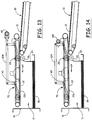
FIG. 14 is an elevational side view of a schematic of a deceleration apparatus in accordance with still another embodiment of the present disclosure having an eccentric roller for reciprocating the movement of the kicker assembly. - The deceleration apparatus and method in accordance with the present disclosure may be used with a sheet stacking machine of the type having an entry conveyor or other sheet delivery means and a stacking hopper. The deceleration apparatus and method and the sheet stacking machine are shown and described with reference to
Figures 1-10 . - With specific reference to
Figure 1 , the sheet stacking machine of one embodiment may include anentry conveyor 10 and a stackinghopper 11. During normal operation, a series ofsheets entry conveyor 10 along a travel path toward the stackinghopper 11. As they reach the discharge end of theentry conveyor 10, thesheets backstop 16 of the stackinghopper 11. The projected sheets may strike the backstop and fall into the hopper where they accumulate in a stack ofsheets 18. The series ofsheets entry conveyor 10 may be formed intostacks 18 of sheets for delivery to a site for further processing or storage. - As shown in
Figures 2-6 , thesheets sheets conveyor 10 and through the deceleration mechanism (described below) in a synchronized manner. In other embodiments, it is recognized that the sheets may be comprised of any suitable number of laterally spaced sheets, including one, two, three, four, or more sheets spaced laterally from one another. Each of thesheets 14, 15 (or 14a, 14b, 15a, 15b) may include aleading edge 52 and a trailingedge 54. The leadingedge 52 may be the front or leading edge of the sheets as they travel along the conveyor in the direction of the arrow 22 (Figure1 ), while the trailing edge may be the back or trailing edge of the sheets as they travel along theconveyor 10 in the direction of thearrow 22. InFigures 1-6 , thesheet 14 may be a sheet which has been projected from theconveyor 10. - It will be understood that the stacking machine may be operable up to a certain maximum entry conveyor speed. If the speed of the
entry conveyor 10 exceeds the maximum operational speed, the momentum of the sheets that are projected from the end of theconveyor 10, may carry the sheets against thebackstop 16 with excessive force. This can cause the sheets to bounce back toward the conveyor, often resulting in the machine being jammed or the sheets being misaligned or skewed in thestack 18. Projecting the sheets at excessive speeds against thebackstop 16 can also result in damage to the leading edge of the sheet. This may particularly be the case if the leading edge includes flaps, tabs, or other protrusions. Accordingly, the sheet stacking machine may have a certain maximum operational entry conveyor speed (normally defined in terms of feet per minute and usually about 500 feet per minute for certain sheets) within which the stacking machine is operational for a sheet of a given size. - To improve the capacity of the sheet stacking machine by increasing the speed of the entry conveyor beyond its normal maximum speed, it may be desirable to slow down or decelerate the sheets as they are projected from the entry conveyor to an acceptable speed. This acceptable speed may be a speed which will not cause the sheets to bounce back or result in damage to the leading edges of the projected sheets. The deceleration means, which is the subject of the present disclosure and further details of the sheet stacking machine and system, are described with reference to
Figures 1-10 . - In one embodiment, the
entry conveyor 10 may be a belt conveyor. Although theconveyor 10 could comprise a single belt extending across the width of the apparatus, theconveyor 10 of the preferred embodiment may be comprised of a plurality of laterally spaced individual belt conveyors orbelt conveyor sections 19. Theseconveyor sections 19 may be laterally spaced from one another and include anendless belt 20. Each of thebelts 20 may be supported by a plurality ofbelt support rollers 21. At least one of the rollers may be driven to provide theroller 10 with its belt or line speed. Thebelts 20 may move in unison to convey thesheets hopper 11 in the direction indicated by thearrow 22 inFigure 1 . Thebelts 20 may be conventional conveyor belts used in the corrugated, paperboard, or other sheet conveyance industry. Although one embodiment shows a sheet stacking machine comprising endless belts as the entry conveyor and as the means for delivering the sheets to the stacking hopper, other means currently known in the art, or which may be made available in the art, to transport or convey sheets may be used as well. Such other means do not alter the advantageous features of the deceleration apparatus and method of the present disclosure. Such other means may include rollers, overhead or underneath vacuum transport mechanisms, or any other similar conveyance or delivery means. Such other means could also comprise top and bottom belts with the sheets sandwiched between them. - It should be noted that the
entry conveyor 10, as shown inFigures 2-6 , is substantially horizontal as it approaches the stacking hopper. While this may be desirable in some situations, theconveyor 10 may be sloped as shown inFigure 1 in situations where elevation at the front end of the conveyor is needed. - The stacking
hopper 11 may include abackstop 16, which is spaced from the forward end of theentry conveyor 10. The distance of this spacing may be adjustable to accommodate sheets of different lengths and may be at least as great as the length of the sheets (measured in the direction of travel) being stacked. The stackinghopper 11 may also include aback tamper 24 extending generally parallel to thebackstop 16. As shown, the back tamper may include a generally vertical wall portion and anupper edge 25, which is sloped toward theentry conveyor 10. This slopingedge 25 may assist in guiding the projected sheets into the stackinghopper 11 between thebackstop 16 and theback tamper 24. This back tamper may be of a conventional design and include means to square thestack 18 and to repeatedly tamp the rear edges of the sheets in the stack toward thebackstop 16 to keep thestack 18 square during the stacking process. The stackinghopper 11 may also be provided with one or more side tampers and a divider if multiple side-by-side sheets are being stacked. In one embodiment, the back tamper may be spaced from the entry conveyor 10 a sufficient distance to accommodate the sheet deceleration apparatus of the present disclosure. - The sheet deceleration apparatus of the present disclosure may include a first or deceleration roller means or
assembly 26 and a second or nip roller means orassembly 28. As shown, the roller means 26 may be positioned below or on one side of the sheet travel path, while the roller means 28 may be positioned above or on the other side of the sheet travel path. These roller means 26 and 28 may be designed for reciprocal movement toward and away from one another to temporarily nip or capture a projected sheet to slow down or decelerate the forward travel speed of that sheet. This may permit theentry conveyor 10 to travel at an increased speed, while at the same time preventing the sheets from being projected against the backstop at excessive speeds that would cause the sheets to bounce back or damage to the leading edge of the sheets. - The
deceleration roller assembly 26 may include a plurality ofdeceleration rollers 29 positioned on one side of the projectedsheet 14. In one embodiment, therollers 29 may be mounted on acommon rotation shaft 30 and spaced from one another laterally across the width of theentry conveyor 10. Theshaft 30, and thus the rotation axis of therollers 29, may be generally perpendicular to the travel path of the sheets. As shown best inFigure 1 , therollers 29 may be positioned at the forward end of theentry conveyor 10. Therollers 29 may be spaced slightly in front of the forward end of theentry conveyor 10, with the top of therollers 29 being at or slightly below the conveying level of theconveyor 10. In a further embodiment, the top of therollers 29 may be slightly below the conveying level of the conveyor 10 (the sheet travel path). This may result in the projected sheet dropping slightly as it is engaged by the nip roller (discussed below) and may eliminate or minimize interference by the leading edge of the following sheet. - The
rollers 29 may also be positioned slightly rearwardly of theback tamper 24. This may permit the projected sheets to fall within the stackinghopper 11 without interference from therollers 29. Therollers 29 may be mounted to thecommon shaft 30 for rotation with theshaft 30. In one embodiment, theshaft 30, and thus therollers 29, may be driven, although some advantages of the present invention may be achieved withrollers 29 which are free spooled or which are provided with a specified rotational resistance. The rollers may be driven at a rotational speed such that the circumferential speed of the outer surface of therollers 29 travels in the same direction as thetravel direction 22 of theconveyor 10, but at a reduced speed. The rotational speed of theshaft 30 androllers 29, and thus the degree of deceleration, may be adjusted so that the circumferential speed of the rollers is about one-half to one-fourth the linear speed of theconveyor 10 or less. However, the degree of deceleration can be any fraction (less than one) of the line speed of theconveyor 10. - As shown best in
Figures 2-6 , the slopingwall section 25 of theback tamper 24 may be provided with a plurality of cutout portions or recesses 31 to accommodate nesting of the rollers in those recesses. Theserecesses 31 may be aligned with therollers 29 and may permit the tamping movement of thetamper 24 without interference between thewall 25 and therollers 29. - The
shaft 30 and thus therollers 29 may be rotatably supported in a portion of the apparatus of frame 32 (Figure 2 ). This position of theshaft 30 relative to theapparatus frame 32 may be spatially fixed during an operational mode. It is also contemplated, however, that means may be provided, if desired, to adjust the vertical and lateral position of theshaft 30 and thus therollers 29 relative to the forward end of theentry conveyor 10. Theshaft 30 and thus therollers 29 may be driven by adeceleration roller motor 34. In one embodiment, thismotor 34 may be a variable speed or variable frequency motor designed to run at a plurality of adjustable constant speeds. These speeds may be sufficient to rotate therollers 29 at a circumferential speed (feet per minute) less than the linear speed at which the sheets are traveling on theconveyor 10. - The
rollers 29 can be made from a variety of materials. In one embodiment, these may include aluminum or aluminum with a urethane coating. Various plastics and other materials may be used as well. - The
nip roller assembly 28 may include a plurality ofindividual rollers 35. As shown, theserollers 35 may be laterally spaced across the width of theentry conveyor 10, with such spacing approximating the spacing of therollers 29. Accordingly, each of therollers 29, in one embodiment, may include an associated orcomplimentary nip roller 35. Therollers 35 may be what are known in the art as zero crush rollers. These are rollers which have a circumferential configuration which eliminates or minimizes any damage to the sheet as it is engaged by therollers 35. - Each of the nip
rollers 35 may be designed for reciprocal movement toward and away from its associateddeceleration roller 29 so as to capture or nip a projected sheet. A variety of structural mechanisms may be designed to provide such relative movement. In one embodiment, this reciprocal movement may be provided by a nip roller pivot arm or link 36 associated with each of therollers 35. Each of thesepivot arms 36 may include arotation end 38 and an oppositefree end 39. The niprollers 35 may be rotatably connected near the free ends 39 of thepivot arms 36 about the pivot axis orshaft 40. These pivot arms orshafts 40 may be generally perpendicular to the travel path of the sheets. The rotation ends 38 of thepivot arms 36 may be rigidly mounted to thepivot shaft 41 in such a manner that pivotal movement of theshaft 41 results in corresponding movement of thepivot arm 36. In one embodiment, theshaft 41 may be common to all of thepivot arms 36 and is mounted for limited pivotal movement within a portion of theapparatus frame 32. - The
pivot shaft 41 may be connected with, and driven by aservo motor 42 through a pair ofdrive links Figure 7 , thedrive link 44 may include a first end, which is rotatably connected with aneccentric shaft 46, which is eccentric to the servomotor output shaft 48. The opposite or free end of thedrive link 44 may be pivotally connected with a free end of thedrive link 45 about thepivot 49. The opposite end of thedrive link 45 may be rigidly secured to thepivot shaft 41 so that movement of thedrive link 45 results in corresponding pivotal movement of thepivot shaft 41. Accordingly, as theoutput shaft 48 of theservo motor 42 rotates, theeccentric shaft 46 may revolve around theshaft 48 and provide a reciprocal movement to thepivot 49 joining thelinks arrow 50. This may result in corresponding reciprocal pivotal movement of thepivot shaft 41 in the direction of thearrow 51. Reciprocal pivotal movement of theshaft 41 may result in corresponding pivotal movement of thepivot arms 36, and thus reciprocal movement of the niprollers 35 toward and away from thedeceleration rollers 29. - The
servo motor 42 may be a conventional servo motor, which is synchronized with the speed of theentry conveyor 10, the press, and other components of the conveyance and processing system. The function of the synchronized servo motor may be to ensure that the reciprocal movement of the niprollers 35 toward and away from thedeceleration rollers 29 engage or nip the projected sheet at the desired point in time (relative to the projected sheet 14) and for the desired length of time to decelerate the sheet from the line speed of theconveyor 10 to a desired lower speed. - A system in which the deceleration apparatus and method of the present invention has particular application is illustrated schematically in
Figure 8 . In such system, corrugated or other sheets of material may be cut from aweb 55 of material by a rotary press ordrum 56. Depending upon the length of the sheets, one revolution of thedrum 56 conventionally may cut out three or six sheets (or more or less for specialty systems). In general, the sheets may be as long as 60 inches or more or as short as 20 inches or less. These sheets may be delivered to theentry conveyor 10 described above. Theentry conveyor 10 may then deliver the sheets, with gaps between the trailing edge of one sheet and the leading edge of an adjacent following sheet to the deceleration apparatus comprised of theroller assemblies hopper 11. In one embodiment, theservo motor 42 which drives the reciprocal movement of thenip roller assembly 28 may be synchronized with theconveyor 10 and thepress 56 via an encoder associated with thedrum 56 and thecontrol 58. Because three, or six, or any other fixed number of sheets may be cut out and transferred to theconveyor 10 during each rotation of thedrum 56, the rotation of theservo motor 42 can be timed via an encoder associated with thedrum 56 so that themotor 42 will correspondingly rotate three, six, or any such other fixed number of times during each rotation of thedrum 56. To control the specific time at which rotation of theservo motor 42 is actuated, a phase shift may be utilized. Through this phase shift, the specific time at which the output shaft of theservo motor 42 is rotated, and thus the time at which the niprollers 35 move toward therollers 29 to engage the projectedsheet 14, may be controlled. Because the finishing machine or thedrum 56 registers the leading edge of each sheet, and because movement of thenip roller 35 and thus actuation of theservo motor 42 may be registered with respect to the trailing edge of each sheet, the primary input to thecontroller 58 may be the length of the sheet. From this input, the phase shift can be calculated so that the niprollers 35 will move toward therollers 29 and engage the projectedsheet 14 shortly before its trailing edge. This engagement of the projected sheet by therollers - When actuated, the
output shaft 48 of theservo motor 42 can be programmed or designed to exhibit a variety of profiles. One such profile may be a continuous and relatively constant rotational profile in which theoutput shaft 48 rotates continuously at a relatively constant speed. A second profile may be one in which theshaft 48 is ramped up and then down through 180° to a stop position and after stopping for a predetermined period of time, ramping up and then down through 180° to a further stop position. A third profile may be a sinusoidal or other profile in which the rotation of theshaft 48 ramps up to a high speed where therollers 35 engage and nip the projected sheet against therollers 29 and then ramp back down to a slow rotational speed as the niprollers 35 are released. Rotation of theshaft 48 of theservo motor 42 exhibiting a sinusoidal profile may be desirable since it appears to provide the smoothest motion. - In one embodiment of the sheet stacking machine in accordance with the present disclosure, an
overhead vacuum conveyor 60 may be used to convey the sheets, 14, 15, etc. over the stackinghopper 11 and over thestack 18. Theoverhead vacuum conveyor 60 may be separate from thedeceleration roller assembly 26 and niproller assembly 28. Unlike prior art deceleration machines having a vacuum conveyor, in one embodiment of the deceleration apparatus in accordance with the present disclosure, the speed of theoverhead vacuum conveyor 60 need not be ramped down to zero and subsequently ramped back up to line speed. Theoverhead vacuum conveyor 60 may be continuously run at line speed. - The
overhead vacuum conveyor 60 may comprise one ormore vacuums 62, which may operate to retain thesheets overhead vacuum conveyor 60. In one embodiment, theoverhead vacuum conveyor 60 may be a belt conveyor. Similar toconveyor 10, theoverhead vacuum conveyor 60 could comprise a single belt extending across the width of the apparatus. However, theoverhead vacuum conveyor 60 may be comprised of a plurality of laterally spaced individual belt conveyors or belt conveyor sections. These conveyor sections may be laterally spaced from one another and include an endless belt. Each of the belts may be supported by a plurality of belt support rollers. At least one of the rollers may be driven to provide the roller with its belt or line speed. The belts may move in unison to convey thesheets overhead vacuum conveyor 60 and toward the stackinghopper 11 in the direction indicated by thearrow 64 inFigure 9 . The belts may be conventional conveyor belts used in the corrugated, paperboard, or other sheet conveyance industry. - It should be noted that the
overhead vacuum conveyor 60, as shown inFigure 9 , is substantially horizontal as it approaches the stackinghopper 11. While this may be desirable in some situations, theoverhead vacuum conveyor 60 may be sloped in situations where elevation at one end of the conveyor is desired. - In a further embodiment, a second nip roller assembly, or
sheet kicker assembly 70, may be used to push, or kick, thesheets overhead vacuum conveyor 60. In one embodiment, thesheet kicker assembly 70 may kick thesheets overhead vacuum conveyor 60 at substantially the same time the trailing edge of thesheets nip roller assembly 28. - In one embodiment, the
sheet kicker assembly 70 may be similar to the niproller assembly 28. Although one embodiment of the sheet kicker assembly is illustrated as being similar to the niproller assembly 28, other means currently known in the art, or which may be made available in the art, to push, or kick, thesheets overhead vacuum conveyor 60 may be used as well. Such other means do not alter the advantageous features of the deceleration apparatus and method of the present disclosure. Such other means may include air pressure (e.g., air bursts), vacuum suction (e.g., in a reverse direction than the vacuum conveyor), or any other similar means for pushing the sheets away from theoverhead vacuum conveyor 60. - As illustrated, the
sheet kicker assembly 70 may include a plurality ofindividual rollers 72. Theserollers 72 may be laterally spaced across the width of theoverhead vacuum conveyor 60. In one embodiment, therollers 72 may be laterally spaced such that the spacing approximates the spacing of therollers 35 of thenip roller assembly 28. However, therollers 72 may be laterally spaced in any suitable configuration. Therollers 72 may be zero crush rollers so as to eliminate or minimize any damage to the sheets as they are engaged by therollers 72. - Each of the
rollers 72 may be designed for reciprocal movement toward and away from thesheets hopper 11 by theoverhead vacuum conveyor 60. A variety of structural mechanisms may be designed to provide such relative movement. In one embodiment, this reciprocal movement may be provided by a kicker roller pivot arm or link 74 associated with each of therollers 72. Each of thesepivot arms 74 may include arotation end 76 and an opposite free end 78 (Figure 10 ). Therollers 72 may be rotatably connected near the free ends 78 of thepivot arms 74 about the pivot axis orshaft 80. These pivot arms orshafts 80 may be generally perpendicular to the travel path of thesheets pivot arms 74 may be rigidly mounted to thepivot shaft 81 in such a manner that pivotal movement of theshaft 81 results in corresponding movement of thepivot arm 74. In a further embodiment, theshaft 81 may be common to all of thepivot arms 74. - In one embodiment, the
pivot shaft 81 may be connected with, and driven by aservo motor 82 through a pair ofdrive links 84 and 86 (Figure 10 ). As shown more specifically inFigure 10 , thedrive link 84 may include a first end, which is rotatably connected with aneccentric shaft 88, which is eccentric to the servomotor output shaft 90. The opposite or free end of thedrive link 84 may be pivotally connected with a free end of thedrive link 86 about thepivot 96. The opposite end of thedrive link 86 may be rigidly secured to thepivot shaft 81 so that movement of thedrive link 86 results in corresponding pivotal movement of thepivot shaft 81. Accordingly, as theoutput shaft 90 of theservo motor 82 rotates, theeccentric shaft 88 may revolve around theshaft 90 and provide a reciprocal movement to thepivot 96 joining thelinks arrow 94. This may result in corresponding reciprocal pivotal movement of thepivot shaft 81 in the direction of thearrow 92. Reciprocal pivotal movement of theshaft 81 may result in corresponding pivotal movement of thepivot arms 74, and thus reciprocal movement of therollers 72 toward and away from thesheets - The
servo motor 82 may be a conventional servo motor, which is synchronized with the speed of theservo motor 42, and therefore,entry conveyor 10, the press, and other components of the conveyance and processing system. The function of thesynchronized servo motor 82 may be to ensure that the reciprocal movement of therollers 72 toward and away from thesheets sheets overhead vacuum conveyor 60 at approximately the time thesheets conveyor 10 to a desired lower speed by thenip roller assembly 28. - In one embodiment,
sheet kicker assembly 70 may be operably independent from thenip roller assembly 28. However, thesheet kicker assembly 70 may be synchronized with thenip roller assembly 28 such that thesheet kicker assembly 70 kicks the sheets at the desired point in time to push the sheets off of theoverhead vacuum conveyor 60 at approximately the time the sheets are decelerated by thenip roller assembly 28. - In a further embodiment, illustrated in
Figure 11 , a belt, chain, or the like 102 may be tensioned between thekicker assembly 70 and thenip roller assembly 28 for assisting thekicker assembly 70 in kicking thesheets overhead vacuum conveyor 60. Particularly, a belt, chain, or the like 102 may be tensioned between therollers 72 of thekicker assembly 70 and the niprollers 35 of thenip roller assembly 28. As such, thesheets vacuum conveyor 60 along more surface area of thesheets - In alternate embodiments, such as that illustrated in
Figure 12 , thesheet kicker assembly 70 may be operably connected to the niproller assembly 28. For example, thesheet kicker assembly 70 and niproller assembly 28 may be run using asingle servo motor 42 and may be connected by link, chain, belt, gears, orother method 104 of operably connecting thesheet kicker assembly 70 and niproller assembly 28. Thus, thesheet kicker assembly 70 and niproller assembly 28 may be generally synchronized such that thesheet kicker assembly 70 kicks the sheets at the desired point in time to push the sheets off of theoverhead vacuum conveyor 60 at approximately the time the sheets are decelerated by thenip roller assembly 28. -
Figure 13 illustrates another embodiment, generally combining the embodiments ofFigures 11 and 12 , wherein abar 106, or other similar mechanism, may extend between thekicker assembly 70 and thenip roller assembly 28 for assisting thekicker assembly 70 in kicking thesheets overhead vacuum conveyor 60, and thesheet kicker assembly 70 and niproller assembly 28 may be run using asingle servo motor 42 by connecting them by link, chain, belt, gears, orother method 104, as described above. - In yet another embodiment, illustrated in
Figure 14 , aneccentric roller 108 or other device providing a constant reciprocal movement of thenip roller assembly 28 and/orkicker assembly 70 may be used in place of theservo motor 42. - The
overhead vacuum conveyor 60 and/orsheet kicker assembly 70 may provide additional control of thesheets hopper 11. For example, theoverhead vacuum conveyor 60 and/orsheet kicker assembly 70 may provide additional control to transfer thesheets hopper 11 in a generally horizontal manner. Similarly, theoverhead vacuum conveyor 60 and/orsheet kicker assembly 70 may keep subsequent incoming sheets away from the previous sheet, as the incoming sheet enters the deceleration apparatus in accordance with the present disclosure. - Having described the structural details of the deceleration apparatus in accordance with the present disclosure, the operation of that apparatus and the method aspect of the present disclosure can be understood and described as follows. During normal operation, a linear series of sheets, 14, 15, etc. may travel along the entry conveyor 10 (or otherwise be delivered at line speed) in the direction of the
arrow 22. These sheets may include a gap between the trailing edge of one sheet and the leading edge of the adjacent following sheet. Because of the speed at which theconveyor 10 is moving, each sheet that reaches the end of the conveyor may be projected off the conveyor toward thebackstop 16. Shortly before the leading edge of the projectedsheet 14 reaches thebackstop 16, the niprollers 35 may be moved downwardly toward thedeceleration rollers 29 via theservo motor 42 and the drive and pivot link assembly. This movement of the niprollers 35 toward thedeceleration rollers 29 may nip or capture the sheet between the rollers. This movement of the niprollers 35 toward thedeceleration rollers 29 may be at a point in time relative to the projected sheet where it nips or captures the projected sheet near its trailing edge or as close to its trailing edge as possible. When the sheet is nipped or captured between the nip and deceleration rollers, the speed of the sheet may be reduced to a speed approximating that of the deceleration roller. This may be a speed that is less than the line speed of theentry conveyor 10. - In an embodiment comprising an
overhead vacuum conveyor 60 andsheet kicker assembly 70, operation of the deceleration apparatus and the method aspect of the present disclosure can be understood and described as follows. During normal operation, a linear series of sheets, 14, 15, etc. may travel along the entry conveyor 10 (or otherwise be delivered at line speed) in the direction of thearrow 22. These sheets may include a gap between the trailing edge of one sheet and the leading edge of the adjacent following sheet. Because of the speed at which theconveyor 10 is moving, each sheet that reaches the end of the conveyor may be projected off the conveyor toward thebackstop 16. Theoverhead vacuum conveyor 60 may retain each sheet generally parallel to the stackinghopper 11 as the sheet is projected toward thebackstop 16. Theoverhead vacuum conveyor 60 may run continuously at substantially line speed. Shortly before the leading edge of the projectedsheet 14 reaches thebackstop 16, the niprollers 35 may be moved downwardly toward thedeceleration rollers 29 via theservo motor 42 and the corresponding drive and pivot link assembly. This movement of the niprollers 35 toward thedeceleration rollers 29 may nip or capture the sheet between the rollers. This movement of the niprollers 35 toward thedeceleration rollers 29 may be at a point in time relative to the projected sheet where it nips or captures the projected sheet near its trailing edge or as close to its trailing edge as possible. When the sheet is nipped or captured between the nip and deceleration rollers, the speed of the sheet may be reduced to a speed approximating that of the deceleration roller. This may be a speed that is less than the line speed of theentry conveyor 10. At substantially the same time the niprollers 35 are moved downwardly toward thedeceleration rollers 29, therollers 72 of thesheet kicker assembly 70 may be moved downwardly toward the sheet viaservo motor 82 and the corresponding drive and pivot link assembly (or viaservo motor 42 using a suitable link, chain, belt, gears, etc. as described previously). This movement of therollers 72 toward the sheet may be at a point in time relative to the projected sheet where it pushes, or kicks, the projected sheet near its leading edge or closer to the leading edge than the location on the sheet where the niprollers 35 nip the projected sheet to decelerate the sheet. - After a short period of time, which may be dependent on the rotation profile of the
servo motor 42, among other factors, the nip roller may be moved away from the deceleration roller, thereby allowing the sheet to continue to travel in the forward direction, but at a reduced speed, into the stackinghopper 11. The extent to which the speed of the sheet is reduced may depend on the speed of theentry conveyor 10, the speed of thedeceleration rollers 29, and the size of the sheets, among other factors. - Although some embodiments contemplate a
servo motor 42 which is synchronized with the speed of theconveyor 10 and the rotation of thedrum 56 as described above, photodetectors or other position detecting means can be utilized to identify or detect the particular position or location of an advancing sheet and trigger the actuation of theservo motor 42 at the desired point in time. Similarly, photodetectors or other position detecting means can be utilized to identify or detect the particular position or location of an advancing sheet and trigger the actuation of theservo motor 82 at the desired point in time for thesheet kicker assembly 70. - Also, although the
deceleration rollers 29 may be spatially fixed relative to theapparatus frame 32, with the niprollers 35 moving in reciprocal relationship toward and away from thedeceleration rollers 29, the reverse could be provided without deviating from the spirit of the present disclosure. For example, the niprollers 35 could be spatially fixed relative to theapparatus frame 32 and the deceleration rollers could be reciprocally moved toward and away from the nip rollers. It is also possible and contemplated by the present disclosure that both the niprollers 35, as well as thedeceleration rollers 29 could be moved toward one another relative to theapparatus frame 32. - In one embodiment the present disclosure contemplates that the nip
rollers 35 could, like thedeceleration rollers 29, be driven. However, the niprollers 35, in other embodiments, may not be driven and may be permitted to free spool and thus assume the speed of the sheet as the nip and deceleration rollers nip or capture the moving sheet. - Although the modified embodiments have been specifically described, it is contemplated that various additional modifications could be made without deviating from the scope of the present invention. Accordingly, the scope of the present invention is solely dictated by the appended claims.
Claims (10)
- A sheet deceleration apparatus for reducing the speed of a sheet (15) of material moving along a travel path (22) at a first speed, the apparatus comprising:a first rotatable roller (26) being rotatable about a first axis, the first axis being substantially perpendicular to the travel path (22) and the first roller (26) being positioned on one side of the travel path (22);a second rotatable roller (28) being rotatable about a second axis, the second axis being substantially perpendicular to the travel path (22) and the second roller (28) being positioned on the other side of the travel path (22) and spaced from the first roller (26) so that the sheet (15) of material can pass between the first and second rollers (26, 28);at least one of the first and second rollers (26, 28) being moveable relative to and toward the other of the first and second rollers (26, 28) to nip the sheet (15) between the first and second rollers (26, 28) during at least a portion of the travel of the sheet (15) past the first and second rollers (26, 28) to reduce the speed of the sheet (15);an overhead vacuum conveyor (60) along the travel path (22) subsequent the first and second rollers (26, 28); characterised by further comprising a third rotatable roller (72) along the travel path (22) subsequent the first and second rollers (26, 28) to push the sheet (15) of material away from the overhead vacuum conveyor (60);wherein the third roller (72) is moveable between a retracted position in which the third roller (72) is sufficiently spaced from the sheet (15) of material so as to not push the sheet (15) away from the overhead vacuum conveyor (60) and an extended position in which the third roller (72) is moved toward, and in contact with, the sheet (15) of material so as to push the sheet (15) away from the overhead vacuum conveyor (60); andwherein the third roller (72) extends to push the sheet (15) of material away from the overhead vacuum conveyor (60) at substantially the same time as the first and second rollers (26, 28) operate to nip the sheet (15) of material to reduce the speed of the sheet (15).
- The sheet deceleration apparatus of Claim 1, wherein the overhead vacuum conveyor (60) runs at a continuous line speed.
- The sheet deceleration apparatus of Claim 2, wherein the overhead vacuum conveyor (60) runs at a line speed that is substantially the same as the first speed of the travel path (22).
- The sheet deceleration apparatus of Claim 1, wherein the third roller (72) is driven independently from the first and second rollers (26, 28).
- The sheet deceleration apparatus of Claim 1, further comprising a linkage assembly between the third roller (72) and one of the first and second rollers (26, 28), such that the movement of the third roller (72) is synchronized with the movement of the one of the first and second rollers (26, 28).
- A method for decelerating a sheet (15) of material traveling along a travel path (22) at a first speed, the method comprising:delivering the sheet (15) of material between first and second rollers (26, 28), the first and second rollers (26, 28) being rotatable on first and second axes, respectively, the first and second axes being substantially perpendicular to the travel path (22);delivering the sheet (15) of material to an overhead vacuum conveyor (60) running at a continuous line speed;driving at least one of the first and second rollers (26, 28) toward the other to nip the sheet (15) of material during at least a portion of the sheet travel between the first and second rollers (26, 28) to reduce the speed of the sheet (15); characterised by further comprisingdriving a third roller (72) toward the sheet (15) of material traveling along the overhead vacuum conveyor (60) to push off the sheet (15) from the overhead vacuum conveyor (60) at substantially the same time as the first and second rollers (26, 28) operate to nip the sheet (15) of material to reduce the speed of the sheet (15), wherein the continuous line speed of the overhead vacuum conveyor (60) is substantially the same as the first speed of the travel path (22).
- The method of Claim 6, wherein a single servo motor is used for driving the third roller (72) and at least one of the first and second rollers (26, 28) in synchronization.
- The method of Claim 6, further comprising forming the sheet (15) of material on a rotary press prior to delivering the sheet (15) of material between the first and second rollers (26, 28).
- A sheet stacking apparatus comprising:an entry conveyor (10) for delivering sheets (15) of material along a travel path (22) toward a discharge end of the entry conveyor (10);a stacking hopper (11) positioned downstream from the discharge end of the entry conveyor (10);a sheet deceleration apparatus positioned between the discharge end of the entry conveyor (10) and the stacking hopper (11) for reducing the travel speed of the sheets (15) of material prior to delivery to the stacking hopper (11);an exit conveyor positioned at least partially downstream of the sheet deceleration apparatus for controlling delivery of the sheets (15) of material to the stacking hopper (11), the exit conveyor comprising a vacuum overhead conveyor (60), wherein the sheet deceleration apparatus comprises a first roller (26) positioned below the travel path (22) and a second roller (28) positioned above the travel path (22), the rollers (26, 28) being moveable relative to each other to nip the sheets (15) between the first and second rollers (26, 28) during at least a portion of the travel of the sheets (15) past the first and second rollers (26, 28); anda kicker apparatus (70) for releasing the sheets (15) of material from the exit conveyor, wherein the kicker apparatus (70) is synchronized with at least one of the first and second rollers (26, 28); characterized in thatthe movement of the kicker apparatus (70) releases the sheets (15) of material from the exit conveyor at substantially the same time as the first and second rollers (26, 28) operate to nip the sheets (15).
- The sheet stacking apparatus of Claim 9, wherein the exit conveyor has a continuous line speed.
Applications Claiming Priority (2)
| Application Number | Priority Date | Filing Date | Title |
|---|---|---|---|
| US12/351,496 US7887040B2 (en) | 2009-01-09 | 2009-01-09 | Sheet deceleration apparatus and method with kicker |
| PCT/US2010/020221 WO2010080805A1 (en) | 2009-01-09 | 2010-01-06 | Sheet deceleration apparatus and method |
Publications (2)
| Publication Number | Publication Date |
|---|---|
| EP2376356A1 EP2376356A1 (en) | 2011-10-19 |
| EP2376356B1 true EP2376356B1 (en) | 2017-11-29 |
Family
ID=41698529
Family Applications (1)
| Application Number | Title | Priority Date | Filing Date |
|---|---|---|---|
| EP10700079.6A Active EP2376356B1 (en) | 2009-01-09 | 2010-01-06 | Sheet deceleration apparatus, method for decelerating a sheet, and a sheet stacking apparatus |
Country Status (5)
| Country | Link |
|---|---|
| US (1) | US7887040B2 (en) |
| EP (1) | EP2376356B1 (en) |
| CA (2) | CA2748967C (en) |
| ES (1) | ES2657468T3 (en) |
| WO (1) | WO2010080805A1 (en) |
Families Citing this family (9)
| Publication number | Priority date | Publication date | Assignee | Title |
|---|---|---|---|---|
| JP2013523568A (en) * | 2010-04-13 | 2013-06-17 | ジェイ・アンド・エル・グループ・インターナショナル・リミテッド・ライアビリティ・カンパニー | Seat reduction device and method |
| CN201873036U (en) * | 2010-11-18 | 2011-06-22 | 佐藤庆根 | Multifunctional vacuum adsorption dispensing machine |
| US9045243B2 (en) | 2011-08-04 | 2015-06-02 | J&L Group International, Llc | Apparatus and method for stacking corrugated sheet material |
| FI123711B (en) * | 2011-12-21 | 2013-09-30 | Raute Oyj | The stacking apparatus |
| ES2685804T3 (en) | 2011-12-28 | 2018-10-11 | Alliance Machine Systems International, Llc | Apparatus and method for stacking items |
| DE102019102774A1 (en) * | 2019-02-05 | 2020-08-06 | Koenig & Bauer Ag | Sheet delivery, a sheet processing machine and a method for operating a sheet processing machine |
| DE102019102775A1 (en) | 2019-02-05 | 2020-08-06 | Koenig & Bauer Ag | Sheet processing machine with shaping device and upper suction transport |
| EP3976515A1 (en) * | 2019-05-31 | 2022-04-06 | SEI S.p.A. | Apparatus for handling and collecting a plurality of substantially bi-dimensional objects |
| CN113100095A (en) * | 2021-02-24 | 2021-07-13 | 邓洋 | Anti-overflow and automatic poultry auxiliary device who feeds and eat |
Citations (2)
| Publication number | Priority date | Publication date | Assignee | Title |
|---|---|---|---|---|
| EP0173959A1 (en) * | 1984-08-30 | 1986-03-12 | Mitsubishi Jukogyo Kabushiki Kaisha | Sheet stacker |
| EP1072548A2 (en) * | 1999-07-29 | 2001-01-31 | LTG Mailänder GmbH | Device for stacking flat goods |
Family Cites Families (8)
| Publication number | Priority date | Publication date | Assignee | Title |
|---|---|---|---|---|
| DE2343678A1 (en) | 1973-08-30 | 1975-03-13 | Schroeter & Bake Werk Fuer Mod | Corrugated sheet laying up installation - suction pressure applied through conveyor bands to move part flexible sheets |
| FI844251L (en) | 1983-12-02 | 1985-06-03 | Beloit Corp | ANORDNING FOER RETARDERING AV I EN SERIESARTAD STROEM LOEPANDE MAOTTSKURNA PAPPERSARK. |
| DD278323A1 (en) | 1988-12-21 | 1990-05-02 | Polygraph Leipzig | DEVICE FOR FORMING A STACK OF HIGH-CHAIN FOLDING FORMS |
| US5904465A (en) | 1997-01-13 | 1999-05-18 | Ward Holding Company | Stacker with discharge control |
| DE19817064A1 (en) | 1997-10-13 | 1999-04-22 | Steinemann Ulrich Ag | Sheet-feeder and automatic stacker with height adjustable delivery table |
| JPH11255392A (en) * | 1998-03-09 | 1999-09-21 | Isowa Corp | Stacking device for sheet stacker, suction conveyor, and suction belt |
| US7052009B2 (en) * | 2003-05-21 | 2006-05-30 | J & L Development, Inc. | Sheet deceleration apparatus and method |
| JP2006044858A (en) | 2004-08-03 | 2006-02-16 | Rengo Co Ltd | Lap conveying device for sheet product |
-
2009
- 2009-01-09 US US12/351,496 patent/US7887040B2/en active Active
-
2010
- 2010-01-06 CA CA2748967A patent/CA2748967C/en active Active
- 2010-01-06 CA CA2965206A patent/CA2965206C/en active Active
- 2010-01-06 ES ES10700079.6T patent/ES2657468T3/en active Active
- 2010-01-06 WO PCT/US2010/020221 patent/WO2010080805A1/en active Application Filing
- 2010-01-06 EP EP10700079.6A patent/EP2376356B1/en active Active
Patent Citations (2)
| Publication number | Priority date | Publication date | Assignee | Title |
|---|---|---|---|---|
| EP0173959A1 (en) * | 1984-08-30 | 1986-03-12 | Mitsubishi Jukogyo Kabushiki Kaisha | Sheet stacker |
| EP1072548A2 (en) * | 1999-07-29 | 2001-01-31 | LTG Mailänder GmbH | Device for stacking flat goods |
Also Published As
| Publication number | Publication date |
|---|---|
| CA2965206C (en) | 2019-07-09 |
| WO2010080805A1 (en) | 2010-07-15 |
| US20100176549A1 (en) | 2010-07-15 |
| CA2748967C (en) | 2017-06-13 |
| ES2657468T3 (en) | 2018-03-05 |
| CA2965206A1 (en) | 2010-07-15 |
| CA2748967A1 (en) | 2010-07-15 |
| US7887040B2 (en) | 2011-02-15 |
| EP2376356A1 (en) | 2011-10-19 |
Similar Documents
| Publication | Publication Date | Title |
|---|---|---|
| EP2376356B1 (en) | Sheet deceleration apparatus, method for decelerating a sheet, and a sheet stacking apparatus | |
| US8827265B2 (en) | Sheet deceleration apparatus and method | |
| US3593624A (en) | Automatic stacking machine | |
| EP0455494B1 (en) | Dual collating machine | |
| EP1565395B1 (en) | Apparatus and method for stacking and separating sheets discharged from a starwheel assembly | |
| EP2739553B1 (en) | Apparatus and method for stacking corrugated sheet material | |
| US5913656A (en) | Method and apparatus for merging shingled signature streams | |
| US7052009B2 (en) | Sheet deceleration apparatus and method | |
| US5904465A (en) | Stacker with discharge control | |
| MXPA04001506A (en) | Starwheel assembly for stacking sheets. | |
| US4682767A (en) | Apparatus for folding and delivering sheet material | |
| US5882175A (en) | Stacker for flexible sheets | |
| JPH06247602A (en) | Apparatus to transfer sheet-shaped article one by one and make its stack by prescribed number | |
| EP0249874A1 (en) | Method and apparatus for transporting signatures along a path between two conveyors | |
| CA2528225C (en) | System and method for transferring blanks | |
| EP0013476B1 (en) | Method of and apparatus for slowing sheets carried by high-speed conveyors before deposit on stationary platforms or low-speed conveyors | |
| US6612570B1 (en) | High speed stacking apparatus | |
| US7478721B2 (en) | Device for conveying sheet-type flat items | |
| US4130207A (en) | Apparatus for stacking booklets from the top | |
| GB2074990A (en) | Sheet delivery and stacking method and apparatus | |
| US3595568A (en) | Jogger stacker machine | |
| US20050082745A1 (en) | Inline stacker with non-interrupt gap generator and integrated drive control and jam response | |
| EP0343001B1 (en) | Multiple stage dispenser | |
| US20050011726A1 (en) | Product transfer system and method |
Legal Events
| Date | Code | Title | Description |
|---|---|---|---|
| PUAI | Public reference made under article 153(3) epc to a published international application that has entered the european phase |
Free format text: ORIGINAL CODE: 0009012 |
|
| 17P | Request for examination filed |
Effective date: 20110705 |
|
| AK | Designated contracting states |
Kind code of ref document: A1 Designated state(s): AT BE BG CH CY CZ DE DK EE ES FI FR GB GR HR HU IE IS IT LI LT LU LV MC MK MT NL NO PL PT RO SE SI SK SM TR |
|
| DAX | Request for extension of the european patent (deleted) | ||
| 17Q | First examination report despatched |
Effective date: 20120417 |
|
| 17Q | First examination report despatched |
Effective date: 20120514 |
|
| RAP1 | Party data changed (applicant data changed or rights of an application transferred) |
Owner name: ALLIANCE MACHINE SYSTEMS INTERNATIONAL, LLC |
|
| RIC1 | Information provided on ipc code assigned before grant |
Ipc: B65G 57/04 20060101ALI20170621BHEP Ipc: B65H 29/32 20060101ALI20170621BHEP Ipc: B65H 29/68 20060101AFI20170621BHEP |
|
| GRAP | Despatch of communication of intention to grant a patent |
Free format text: ORIGINAL CODE: EPIDOSNIGR1 |
|
| INTG | Intention to grant announced |
Effective date: 20170728 |
|
| GRAS | Grant fee paid |
Free format text: ORIGINAL CODE: EPIDOSNIGR3 |
|
| GRAA | (expected) grant |
Free format text: ORIGINAL CODE: 0009210 |
|
| AK | Designated contracting states |
Kind code of ref document: B1 Designated state(s): AT BE BG CH CY CZ DE DK EE ES FI FR GB GR HR HU IE IS IT LI LT LU LV MC MK MT NL NO PL PT RO SE SI SK SM TR |
|
| REG | Reference to a national code |
Ref country code: CH Ref legal event code: EP |
|
| REG | Reference to a national code |
Ref country code: AT Ref legal event code: REF Ref document number: 950173 Country of ref document: AT Kind code of ref document: T Effective date: 20171215 |
|
| REG | Reference to a national code |
Ref country code: IE Ref legal event code: FG4D |
|
| REG | Reference to a national code |
Ref country code: DE Ref legal event code: R096 Ref document number: 602010047002 Country of ref document: DE |
|
| REG | Reference to a national code |
Ref country code: FR Ref legal event code: PLFP Year of fee payment: 9 |
|
| REG | Reference to a national code |
Ref country code: ES Ref legal event code: FG2A Ref document number: 2657468 Country of ref document: ES Kind code of ref document: T3 Effective date: 20180305 |
|
| REG | Reference to a national code |
Ref country code: NL Ref legal event code: FP |
|
| REG | Reference to a national code |
Ref country code: LT Ref legal event code: MG4D |
|
| REG | Reference to a national code |
Ref country code: AT Ref legal event code: MK05 Ref document number: 950173 Country of ref document: AT Kind code of ref document: T Effective date: 20171129 |
|
| PG25 | Lapsed in a contracting state [announced via postgrant information from national office to epo] |
Ref country code: LT Free format text: LAPSE BECAUSE OF FAILURE TO SUBMIT A TRANSLATION OF THE DESCRIPTION OR TO PAY THE FEE WITHIN THE PRESCRIBED TIME-LIMIT Effective date: 20171129 Ref country code: NO Free format text: LAPSE BECAUSE OF FAILURE TO SUBMIT A TRANSLATION OF THE DESCRIPTION OR TO PAY THE FEE WITHIN THE PRESCRIBED TIME-LIMIT Effective date: 20180228 Ref country code: FI Free format text: LAPSE BECAUSE OF FAILURE TO SUBMIT A TRANSLATION OF THE DESCRIPTION OR TO PAY THE FEE WITHIN THE PRESCRIBED TIME-LIMIT Effective date: 20171129 Ref country code: SE Free format text: LAPSE BECAUSE OF FAILURE TO SUBMIT A TRANSLATION OF THE DESCRIPTION OR TO PAY THE FEE WITHIN THE PRESCRIBED TIME-LIMIT Effective date: 20171129 |
|
| PG25 | Lapsed in a contracting state [announced via postgrant information from national office to epo] |
Ref country code: BG Free format text: LAPSE BECAUSE OF FAILURE TO SUBMIT A TRANSLATION OF THE DESCRIPTION OR TO PAY THE FEE WITHIN THE PRESCRIBED TIME-LIMIT Effective date: 20180228 Ref country code: GR Free format text: LAPSE BECAUSE OF FAILURE TO SUBMIT A TRANSLATION OF THE DESCRIPTION OR TO PAY THE FEE WITHIN THE PRESCRIBED TIME-LIMIT Effective date: 20180301 Ref country code: AT Free format text: LAPSE BECAUSE OF FAILURE TO SUBMIT A TRANSLATION OF THE DESCRIPTION OR TO PAY THE FEE WITHIN THE PRESCRIBED TIME-LIMIT Effective date: 20171129 Ref country code: HR Free format text: LAPSE BECAUSE OF FAILURE TO SUBMIT A TRANSLATION OF THE DESCRIPTION OR TO PAY THE FEE WITHIN THE PRESCRIBED TIME-LIMIT Effective date: 20171129 Ref country code: LV Free format text: LAPSE BECAUSE OF FAILURE TO SUBMIT A TRANSLATION OF THE DESCRIPTION OR TO PAY THE FEE WITHIN THE PRESCRIBED TIME-LIMIT Effective date: 20171129 |
|
| PG25 | Lapsed in a contracting state [announced via postgrant information from national office to epo] |
Ref country code: CY Free format text: LAPSE BECAUSE OF FAILURE TO SUBMIT A TRANSLATION OF THE DESCRIPTION OR TO PAY THE FEE WITHIN THE PRESCRIBED TIME-LIMIT Effective date: 20171129 Ref country code: DK Free format text: LAPSE BECAUSE OF FAILURE TO SUBMIT A TRANSLATION OF THE DESCRIPTION OR TO PAY THE FEE WITHIN THE PRESCRIBED TIME-LIMIT Effective date: 20171129 Ref country code: EE Free format text: LAPSE BECAUSE OF FAILURE TO SUBMIT A TRANSLATION OF THE DESCRIPTION OR TO PAY THE FEE WITHIN THE PRESCRIBED TIME-LIMIT Effective date: 20171129 Ref country code: CZ Free format text: LAPSE BECAUSE OF FAILURE TO SUBMIT A TRANSLATION OF THE DESCRIPTION OR TO PAY THE FEE WITHIN THE PRESCRIBED TIME-LIMIT Effective date: 20171129 Ref country code: SK Free format text: LAPSE BECAUSE OF FAILURE TO SUBMIT A TRANSLATION OF THE DESCRIPTION OR TO PAY THE FEE WITHIN THE PRESCRIBED TIME-LIMIT Effective date: 20171129 |
|
| REG | Reference to a national code |
Ref country code: DE Ref legal event code: R097 Ref document number: 602010047002 Country of ref document: DE |
|
| PG25 | Lapsed in a contracting state [announced via postgrant information from national office to epo] |
Ref country code: SM Free format text: LAPSE BECAUSE OF FAILURE TO SUBMIT A TRANSLATION OF THE DESCRIPTION OR TO PAY THE FEE WITHIN THE PRESCRIBED TIME-LIMIT Effective date: 20171129 Ref country code: RO Free format text: LAPSE BECAUSE OF FAILURE TO SUBMIT A TRANSLATION OF THE DESCRIPTION OR TO PAY THE FEE WITHIN THE PRESCRIBED TIME-LIMIT Effective date: 20171129 Ref country code: IT Free format text: LAPSE BECAUSE OF FAILURE TO SUBMIT A TRANSLATION OF THE DESCRIPTION OR TO PAY THE FEE WITHIN THE PRESCRIBED TIME-LIMIT Effective date: 20171129 Ref country code: PL Free format text: LAPSE BECAUSE OF FAILURE TO SUBMIT A TRANSLATION OF THE DESCRIPTION OR TO PAY THE FEE WITHIN THE PRESCRIBED TIME-LIMIT Effective date: 20171129 |
|
| REG | Reference to a national code |
Ref country code: CH Ref legal event code: PL |
|
| PLBE | No opposition filed within time limit |
Free format text: ORIGINAL CODE: 0009261 |
|
| STAA | Information on the status of an ep patent application or granted ep patent |
Free format text: STATUS: NO OPPOSITION FILED WITHIN TIME LIMIT |
|
| PG25 | Lapsed in a contracting state [announced via postgrant information from national office to epo] |
Ref country code: LU Free format text: LAPSE BECAUSE OF NON-PAYMENT OF DUE FEES Effective date: 20180106 |
|
| REG | Reference to a national code |
Ref country code: IE Ref legal event code: MM4A |
|
| 26N | No opposition filed |
Effective date: 20180830 |
|
| PG25 | Lapsed in a contracting state [announced via postgrant information from national office to epo] |
Ref country code: CH Free format text: LAPSE BECAUSE OF NON-PAYMENT OF DUE FEES Effective date: 20180131 Ref country code: LI Free format text: LAPSE BECAUSE OF NON-PAYMENT OF DUE FEES Effective date: 20180131 Ref country code: SI Free format text: LAPSE BECAUSE OF FAILURE TO SUBMIT A TRANSLATION OF THE DESCRIPTION OR TO PAY THE FEE WITHIN THE PRESCRIBED TIME-LIMIT Effective date: 20171129 |
|
| PG25 | Lapsed in a contracting state [announced via postgrant information from national office to epo] |
Ref country code: IE Free format text: LAPSE BECAUSE OF NON-PAYMENT OF DUE FEES Effective date: 20180106 |
|
| PG25 | Lapsed in a contracting state [announced via postgrant information from national office to epo] |
Ref country code: MC Free format text: LAPSE BECAUSE OF FAILURE TO SUBMIT A TRANSLATION OF THE DESCRIPTION OR TO PAY THE FEE WITHIN THE PRESCRIBED TIME-LIMIT Effective date: 20171129 |
|
| PG25 | Lapsed in a contracting state [announced via postgrant information from national office to epo] |
Ref country code: MT Free format text: LAPSE BECAUSE OF NON-PAYMENT OF DUE FEES Effective date: 20180106 |
|
| PG25 | Lapsed in a contracting state [announced via postgrant information from national office to epo] |
Ref country code: TR Free format text: LAPSE BECAUSE OF FAILURE TO SUBMIT A TRANSLATION OF THE DESCRIPTION OR TO PAY THE FEE WITHIN THE PRESCRIBED TIME-LIMIT Effective date: 20171129 |
|
| PG25 | Lapsed in a contracting state [announced via postgrant information from national office to epo] |
Ref country code: PT Free format text: LAPSE BECAUSE OF FAILURE TO SUBMIT A TRANSLATION OF THE DESCRIPTION OR TO PAY THE FEE WITHIN THE PRESCRIBED TIME-LIMIT Effective date: 20171129 Ref country code: HU Free format text: LAPSE BECAUSE OF FAILURE TO SUBMIT A TRANSLATION OF THE DESCRIPTION OR TO PAY THE FEE WITHIN THE PRESCRIBED TIME-LIMIT; INVALID AB INITIO Effective date: 20100106 |
|
| PG25 | Lapsed in a contracting state [announced via postgrant information from national office to epo] |
Ref country code: MK Free format text: LAPSE BECAUSE OF NON-PAYMENT OF DUE FEES Effective date: 20171129 |
|
| PG25 | Lapsed in a contracting state [announced via postgrant information from national office to epo] |
Ref country code: IS Free format text: LAPSE BECAUSE OF FAILURE TO SUBMIT A TRANSLATION OF THE DESCRIPTION OR TO PAY THE FEE WITHIN THE PRESCRIBED TIME-LIMIT Effective date: 20180329 |
|
| PGFP | Annual fee paid to national office [announced via postgrant information from national office to epo] |
Ref country code: NL Payment date: 20221220 Year of fee payment: 14 Ref country code: GB Payment date: 20221221 Year of fee payment: 14 Ref country code: FR Payment date: 20221220 Year of fee payment: 14 |
|
| PGFP | Annual fee paid to national office [announced via postgrant information from national office to epo] |
Ref country code: BE Payment date: 20221220 Year of fee payment: 14 |
|
| PGFP | Annual fee paid to national office [announced via postgrant information from national office to epo] |
Ref country code: ES Payment date: 20230201 Year of fee payment: 14 |
|
| PGFP | Annual fee paid to national office [announced via postgrant information from national office to epo] |
Ref country code: DE Payment date: 20221220 Year of fee payment: 14 |
|
| P01 | Opt-out of the competence of the unified patent court (upc) registered |
Effective date: 20230529 |