EP2376216B1 - Stir system and a method for providing a chemical reaction - Google Patents
Stir system and a method for providing a chemical reaction Download PDFInfo
- Publication number
- EP2376216B1 EP2376216B1 EP10703128.8A EP10703128A EP2376216B1 EP 2376216 B1 EP2376216 B1 EP 2376216B1 EP 10703128 A EP10703128 A EP 10703128A EP 2376216 B1 EP2376216 B1 EP 2376216B1
- Authority
- EP
- European Patent Office
- Prior art keywords
- vial
- stirrer
- stir system
- providing
- holder
- Prior art date
- Legal status (The legal status is an assumption and is not a legal conclusion. Google has not performed a legal analysis and makes no representation as to the accuracy of the status listed.)
- Active
Links
Images


Classifications
-
- B—PERFORMING OPERATIONS; TRANSPORTING
- B01—PHYSICAL OR CHEMICAL PROCESSES OR APPARATUS IN GENERAL
- B01F—MIXING, e.g. DISSOLVING, EMULSIFYING OR DISPERSING
- B01F33/00—Other mixers; Mixing plants; Combinations of mixers
- B01F33/45—Magnetic mixers; Mixers with magnetically driven stirrers
- B01F33/453—Magnetic mixers; Mixers with magnetically driven stirrers using supported or suspended stirring elements
-
- B—PERFORMING OPERATIONS; TRANSPORTING
- B01—PHYSICAL OR CHEMICAL PROCESSES OR APPARATUS IN GENERAL
- B01F—MIXING, e.g. DISSOLVING, EMULSIFYING OR DISPERSING
- B01F33/00—Other mixers; Mixing plants; Combinations of mixers
- B01F33/50—Movable or transportable mixing devices or plants
- B01F33/501—Movable mixing devices, i.e. readily shifted or displaced from one place to another, e.g. portable during use
- B01F33/5011—Movable mixing devices, i.e. readily shifted or displaced from one place to another, e.g. portable during use portable during use, e.g. hand-held
- B01F33/50111—Small portable bottles, flasks, vials, e.g. with means for mixing ingredients or for homogenizing their content, e.g. by hand shaking
-
- B—PERFORMING OPERATIONS; TRANSPORTING
- B01—PHYSICAL OR CHEMICAL PROCESSES OR APPARATUS IN GENERAL
- B01F—MIXING, e.g. DISSOLVING, EMULSIFYING OR DISPERSING
- B01F33/00—Other mixers; Mixing plants; Combinations of mixers
- B01F33/45—Magnetic mixers; Mixers with magnetically driven stirrers
- B01F33/453—Magnetic mixers; Mixers with magnetically driven stirrers using supported or suspended stirring elements
- B01F33/4535—Magnetic mixers; Mixers with magnetically driven stirrers using supported or suspended stirring elements using a stud for supporting the stirring element
-
- B—PERFORMING OPERATIONS; TRANSPORTING
- B01—PHYSICAL OR CHEMICAL PROCESSES OR APPARATUS IN GENERAL
- B01F—MIXING, e.g. DISSOLVING, EMULSIFYING OR DISPERSING
- B01F33/00—Other mixers; Mixing plants; Combinations of mixers
- B01F33/50—Movable or transportable mixing devices or plants
- B01F33/501—Movable mixing devices, i.e. readily shifted or displaced from one place to another, e.g. portable during use
- B01F33/5011—Movable mixing devices, i.e. readily shifted or displaced from one place to another, e.g. portable during use portable during use, e.g. hand-held
-
- B—PERFORMING OPERATIONS; TRANSPORTING
- B01—PHYSICAL OR CHEMICAL PROCESSES OR APPARATUS IN GENERAL
- B01F—MIXING, e.g. DISSOLVING, EMULSIFYING OR DISPERSING
- B01F33/00—Other mixers; Mixing plants; Combinations of mixers
- B01F33/86—Mixing heads comprising a driven stirrer
-
- B—PERFORMING OPERATIONS; TRANSPORTING
- B01—PHYSICAL OR CHEMICAL PROCESSES OR APPARATUS IN GENERAL
- B01F—MIXING, e.g. DISSOLVING, EMULSIFYING OR DISPERSING
- B01F35/00—Accessories for mixers; Auxiliary operations or auxiliary devices; Parts or details of general application
- B01F35/20—Measuring; Control or regulation
- B01F35/21—Measuring
- B01F35/211—Measuring of the operational parameters
- B01F35/2114—Speed of feeding material, e.g. bands or strips
-
- B—PERFORMING OPERATIONS; TRANSPORTING
- B01—PHYSICAL OR CHEMICAL PROCESSES OR APPARATUS IN GENERAL
- B01F—MIXING, e.g. DISSOLVING, EMULSIFYING OR DISPERSING
- B01F35/00—Accessories for mixers; Auxiliary operations or auxiliary devices; Parts or details of general application
- B01F35/20—Measuring; Control or regulation
- B01F35/21—Measuring
- B01F35/212—Measuring of the driving system data, e.g. torque, speed or power data
-
- B—PERFORMING OPERATIONS; TRANSPORTING
- B01—PHYSICAL OR CHEMICAL PROCESSES OR APPARATUS IN GENERAL
- B01F—MIXING, e.g. DISSOLVING, EMULSIFYING OR DISPERSING
- B01F35/00—Accessories for mixers; Auxiliary operations or auxiliary devices; Parts or details of general application
- B01F35/20—Measuring; Control or regulation
- B01F35/22—Control or regulation
- B01F35/221—Control or regulation of operational parameters, e.g. level of material in the mixer, temperature or pressure
- B01F35/2214—Speed during the operation
- B01F35/22142—Speed of the mixing device during the operation
- B01F35/221422—Speed of rotation of the mixing axis, stirrer or receptacle during the operation
-
- B—PERFORMING OPERATIONS; TRANSPORTING
- B01—PHYSICAL OR CHEMICAL PROCESSES OR APPARATUS IN GENERAL
- B01F—MIXING, e.g. DISSOLVING, EMULSIFYING OR DISPERSING
- B01F2101/00—Mixing characterised by the nature of the mixed materials or by the application field
- B01F2101/23—Mixing of laboratory samples e.g. in preparation of analysing or testing properties of materials
Definitions
- Stir systems may be used for stirring and mixing a liquid in a vial.
- US 2,350,534 discloses a magnetic stirrer which will operate by magnetic action. A magnetic stirrer is put in the vial and by providing a rotating magnetic field the stirrer is rotated in the vial.
- WO2008/112395 discloses a stirring apparatus which can be inserted in a liquid sample.
- the stirring apparatus is provided with a handle or grip portion.
- US2003/0128626 discloses an apparatus for the addition of a compound or compound mixture to another including a primary and a secondary vessel.
- the secondary vessel is moveably mounted in the primary vessel for movement between a stored position and a mixing position.
- WO97/15366 discloses a distillation vessel with a combination stirrer.
- the actual paddle of the stirrer contains two magnets and is rotated outside the tube by the drive magnet.
- stir system for stirring a liquid in a vial, the stir system comprising:
- the top may be provided with an exit for providing a gas exit for gas from the vial.
- the exit may be connectable with a tube.
- the top may be provided with an entrance for providing a gas to the vial.
- the entrance may be connectable with a tube.
- the top may be provided with a cooling element constructed and arranged for cooling a vapour above the liquid in the vial. This may be necessary for a reflux reaction in the vial.
- the holder may be provided with a moveable magnet for providing the rotating magnet field.
- the rotating magnet field may be generated with an electro magnet.
- the holder may comprise a measurement device for measuring the rotational speed of the stirrer.
- the measurement device may be an optical sensor.
- the measurement device may be an induction measurement device for measuring the induction by the magnet.
- the stir system may comprise a control device constructed and arranged to adjust the speed of the rotating magnetic field if the measurement system measures a change in the rotational speed of the stirrer.
- the cooling element is a metal element and the system is provided with a holder which has a cooling device in contact with the metal element so as to cool the metal element.
- the top is partially closing the vial.
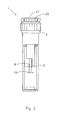
- FIG. 1 schematically depicts a cross-sectional view on a stir system 1 according to the invention.
- the stir system is provided with a top 3, which closes a vial 5 with a liquid 7.
- the stir system is provided with a stirrer 9 rotatable mounted in the top 3 and provided with a stirrer magnet 11. By providing a rotating magnet field to the stirrer magnet 11 the stirrer 9 may be rotated so as to stir the liquid 7.
- the top 3 and the vial 5 may be provided with a screw thread 13 for screwing the top 3 on the vial 5.
- the stirrer 9 may be provided with a blade 15 for stirring the liquid 7.
- the top 3 may be provided with an exit 17 for providing a gas exit for gas from the interior of the vial 5.
- the exit 17 may be connected with a tube to a vacuum pump (not shown) or may be closed off.
- the exit 17 may also be used for sampling of the liquid 7, for example by putting a needle of a syringe through the exit 17 into the liquid 7 to take a sample.
- the top may be provided with an entrance 19 for providing a gas to the vial 5 just above the level where the liquid 7 is.
- the entrance 19 may be connected with a tube for providing the gas to the interior of the vial 5.
- the top may be provided with a lid 21 which may be used to open the top 3.
- the stirrer 9 may be moved a little up relative to the liquid 7 so as to remove the stirrer magnet 11 from the circular member 23.
- the circular member may be provided with a lower part 25, which functions as a bearing for the stirrer 9.
- the circular member 23 may be provided with a screw thread for removably connecting to the rest of the stirrer 9.
- the circular member 23 and the lower part 25 may be made of a plastic, for example TeflonTM so as to provide low friction rotation of the stirrer 9 in the top 3.
- a lower bearing 27 may be used to provide for bearing of the stirrer 9 at the lower end of the top 3.
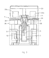
- Figure 2 depicts a view on the stir system 1 of figure 1 .
- the top 3 may be provided with a top grip to provide for grip if the user releases the top 3 from the vial 5.
- the lid 21 may be provided with lid grip 29 to provide for grip if the lid 21 is released from the top 3.
- the blade 15 of the stirrer 9 is shown in a slightly rotated position with respect to the stir system of figure 1 .
- Figure 3 depicts a view on the stir system 1 of figure 1 provided with a holder 30 for holding the vial 5.
- the holder 30 is provided with a cover 31 provided with two driving magnets 33a and 33b, for example coils for providing a rotating magnet field so as to drive the stirrer magnet 11 in a rotational direction.
- the rotating stirrer magnet 11 will be driving the stirrer 9 so as to rotate the blade 15 which stirs the liquid 7.
- the cover 31 may be connected with a hinge to the rest of the holder for opening the cover 31 from the holder 30.
- the vial 5 and the top 3 with the stirrer 9 is kept relatively simple and light weight in this way while the heavy driving electromagnets 33 with their electric connections may be provided to the cover 31.
- the vial 5 and the top 3 may be kept easily moveable for a user in this way.
- a rubber 34 e.g. an O-ring
- This may assure that no liquid may escape from the stir system.
- the holder 30 may be provided with a heater for heating the vial 5.
- the top 3 may be provided with a cooling element which may cool a vapour above the liquid so that the vapour condenses and will drop back into the liquid for reflux.
- the cooling element may be a metal cooled with a cooling device 35 (e.g. a piezo element or a chiller) surrounding the top 3.
- the holder 30 may be provided with a measurement device, for example an optical measurement device or a coil induction measurement device for measuring the rotational speed of the stirrer 9.
- the coil induction measurement device may measure the induction in a coil caused by the rotating magnet 11.
- the coil for measuring the induction may be part of the driving magnets 33a or 33b or may be a separate coil.
- a controller for controlling the rotational speed of the stirrer may be connected with the measurement device and with the driving magnets 33a and 33b. The controller may adjust the rotational speed of the stirrer 9 if the viscosity of the liquid 7 changes. This may be advantageous for example if the reaction starts with a liquid 7 with a very high viscosity and stirring is started with a very low speed.
- the stirring speed may be increased if the viscosity decreases by a pre-programmed program or the measurement device for measuring the rotational speed of the stirrer may provide feedback that the viscosity decreases.
- the control system may than increase the rotational speed of the stirrer.
- the control system takes care that the rotating magnetic field is commutated with the stirrer magnet 11 and the speed of the rotating magnetic field may be decreased if the rotational speed of the stirrer decreases by increasing viscosity. This may circumvent grinding of any crystals that may grow in the liquid 7.
- the driving magnets 33a and 33b may be rotated with an electromotor so as to provide the rotating magnetic field or the driving magnets 33a and 33b may be stationary electro magnets which magnetic field may be adjusted to create a rotating magnet field.
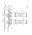
- Figure 4 discloses a perspective side/bottom view on a stir system for parallel processing of two vials 5 in which a portion of the holder is left away to show the details of the driving magnets 33a to 33f.
- the driving magnets 33a to 33f may be electromagnets.
- the driving magnets may be provided to a cover 31 from which a plate 36 is shown. It may be possible to open the cover 31 so as to position the vials 5 in the holder 30 when the cover and the magnets are moved away from the holder 30. This assures easy assess to the vials and easy mobility of the vials 5.
- the plate 36 may be made from metal preferably magnetic metal such as iron, nickel or cobalt so as to increase the strength of the magnet field produced.
- the cover may be provided with holes so as to position the vials 5 through holes in the plate 36.
- the driving magnets 33a to 33f are provided with pole shoes 38 so as to increase the magnetic field of the driving magnet.
- the pole shoes may be made from a magnetic metal such as iron, nickel or cobalt so as to increase the strength of the magnet field produced.
- Four driving magnets for example 33a to 33d may be used to rotate the stirrer 9a in a first vial 5 and four driving magnets 33b 33d, 33e and 33f may be used to rotate the stirrer 9b in the second vial 5.
- the driving magnets 33b and 33d function for both vials 5.
- the stirrer may therefore be rotating in opposite directions or the driving magnets 33b and 33d may be adapted so as to control the direction of both stirrers 9.
- the vials 5 are provided with a top 3 enclosing the liquid 7 in the vials 5.
- Figure 5 discloses a side view on the stir system of figure 4 .
- signalling lights 35 for example a light emitting diode may be present for indicating that the stirrer is functioning. This may help to prevent a situation that a user opens the cover 31 while the stirrer is rotating.
- Figure 6 discloses a bottom view on the stir system.
- the plate 36 is shown comprising the signalling lights 35.
- the vials 5 are surrounded by the driving magnets 33a to 33f with their respective pole shoes 38.
- the electromagnets may be replaced by rotating permanent magnets or the magnets may be removed from the cover 31 to the lower part of the holder.
- the invention may take the form of a computer program containing one or more sequences of machine-readable instructions describing a method as disclosed above, or a data storage medium (e.g. semiconductor memory, magnetical or optical disk) having such a computer program stored therein.
Landscapes
- Chemical & Material Sciences (AREA)
- Chemical Kinetics & Catalysis (AREA)
- Mixers With Rotating Receptacles And Mixers With Vibration Mechanisms (AREA)
- Physical Or Chemical Processes And Apparatus (AREA)
Description
- Stir systems may be used for stirring and mixing a liquid in a vial.
US 2,350,534 discloses a magnetic stirrer which will operate by magnetic action. A magnetic stirrer is put in the vial and by providing a rotating magnetic field the stirrer is rotated in the vial. -
WO2008/112395 discloses a stirring apparatus which can be inserted in a liquid sample. The stirring apparatus is provided with a handle or grip portion. -
US2003/0128626 discloses an apparatus for the addition of a compound or compound mixture to another including a primary and a secondary vessel. The secondary vessel is moveably mounted in the primary vessel for movement between a stored position and a mixing position. -
US 4,325,914 discloses a laboratory pressure vessel with a magnetic drive for mechanical stirring. This document discloses a stir system in accordance with the preamble ofclaim 1. -
WO97/15366 - It is an object of the invention to provide an improvement or at least an alternative for the above mentioned stir system. According to an embodiment of the invention there is provided a stir system for stirring a liquid in a vial, the stir system comprising:
- the vial;
- a top constructed for mounting on the vial; and,
- a stirrer rotatable mounted in the top and during use extending from the top into the vial; the stirrer being connected with a stirrer magnet rotatable during use by a rotating magnet field so as to rotate the stirrer, wherein the top closes the vial and the system comprises:
- a holder for holding the vial;
- a cover for covering the vial and the top in the holder; and the holder or the cover is provided with driving magnets for providing a rotating magnet field for the stirrer magnet.
- The top may be provided with an exit for providing a gas exit for gas from the vial. The exit may be connectable with a tube. The top may be provided with an entrance for providing a gas to the vial. The entrance may be connectable with a tube.
- The top may be provided with a cooling element constructed and arranged for cooling a vapour above the liquid in the vial. This may be necessary for a reflux reaction in the vial.
- The holder may be provided with a moveable magnet for providing the rotating magnet field. The rotating magnet field may be generated with an electro magnet. The holder may comprise a measurement device for measuring the rotational speed of the stirrer. The measurement device may be an optical sensor. The measurement device may be an induction measurement device for measuring the induction by the magnet. The stir system may comprise a control device constructed and arranged to adjust the speed of the rotating magnetic field if the measurement system measures a change in the rotational speed of the stirrer.
- The cooling element is a metal element and the system is provided with a holder which has a cooling device in contact with the metal element so as to cool the metal element. The top is partially closing the vial.
- According to an embodiment of the invention there is provided a method for providing a chemical reaction, in accordance with
claim 15, comprising: - providing a vial
- providing a liquid in the vial;
- providing a stirrer connected to a stirrer magnet rotatable in a top;
- mounting the top on the vial closing the vial;
- providing the vial in a holder
- closing a cover over the holder; and,
- providing a rotating magnet field to the stirrer magnet of the stirrer so as to
- rotate the stirrer in the liquid.
- Embodiments of the invention will now be described, by way of example only, with reference to the accompanying schematic drawings in which corresponding reference symbols indicate corresponding parts, and in which:
-
Figure 1 depicts a schematic cross-sectional view on a stir system according to the invention; -
Figure 2 depicts a view on the stir system offigure 1 ; -
Figure 3 depicts a view on the stir system offigure 1 provided with a holder for holding the vial; -
Figure 4 discloses a perspective side/bottom view on a stir system comprising two vials; -
Figure 5 discloses a side view on the stir system offigure 4 ; and, -
Figure 6 discloses a top view on the stir system offigure 4 . -
Figure 1 schematically depicts a cross-sectional view on astir system 1 according to the invention. The stir system is provided with atop 3, which closes avial 5 with aliquid 7. The stir system is provided with astirrer 9 rotatable mounted in thetop 3 and provided with astirrer magnet 11. By providing a rotating magnet field to thestirrer magnet 11 thestirrer 9 may be rotated so as to stir theliquid 7. Thetop 3 and thevial 5 may be provided with ascrew thread 13 for screwing thetop 3 on thevial 5. Thestirrer 9 may be provided with ablade 15 for stirring theliquid 7. - The
top 3 may be provided with anexit 17 for providing a gas exit for gas from the interior of thevial 5. Theexit 17 may be connected with a tube to a vacuum pump (not shown) or may be closed off. Theexit 17 may also be used for sampling of theliquid 7, for example by putting a needle of a syringe through theexit 17 into theliquid 7 to take a sample. The top may be provided with anentrance 19 for providing a gas to thevial 5 just above the level where theliquid 7 is. Theentrance 19 may be connected with a tube for providing the gas to the interior of thevial 5. - For ease of use the top may be provided with a
lid 21 which may be used to open thetop 3. Thestirrer 9 may be moved a little up relative to theliquid 7 so as to remove thestirrer magnet 11 from thecircular member 23. The circular member may be provided with alower part 25, which functions as a bearing for thestirrer 9. Thecircular member 23 may be provided with a screw thread for removably connecting to the rest of thestirrer 9. Preferably thecircular member 23 and thelower part 25 may be made of a plastic, for example Teflon™ so as to provide low friction rotation of thestirrer 9 in thetop 3. Alower bearing 27 may be used to provide for bearing of thestirrer 9 at the lower end of the top 3. -
Figure 2 depicts a view on thestir system 1 offigure 1 . The top 3 may be provided with a top grip to provide for grip if the user releases the top 3 from thevial 5. Thelid 21 may be provided withlid grip 29 to provide for grip if thelid 21 is released from the top 3. Theblade 15 of thestirrer 9 is shown in a slightly rotated position with respect to the stir system offigure 1 . -
Figure 3 depicts a view on thestir system 1 offigure 1 provided with aholder 30 for holding thevial 5. Theholder 30 is provided with acover 31 provided with two drivingmagnets stirrer magnet 11 in a rotational direction. Therotating stirrer magnet 11 will be driving thestirrer 9 so as to rotate theblade 15 which stirs theliquid 7. Thecover 31 may be connected with a hinge to the rest of the holder for opening thecover 31 from theholder 30. Thevial 5 and the top 3 with thestirrer 9 is kept relatively simple and light weight in this way while the heavy driving electromagnets 33 with their electric connections may be provided to thecover 31. Thevial 5 and the top 3 may be kept easily moveable for a user in this way. To close the space between thecover 31 and the rest of theholder 30, a rubber 34 (e.g. an O-ring) may be provided between thecover 31 and the rest of theholder 30. This may assure that no liquid may escape from the stir system. - The
holder 30 may be provided with a heater for heating thevial 5. The top 3 may be provided with a cooling element which may cool a vapour above the liquid so that the vapour condenses and will drop back into the liquid for reflux. The cooling element may be a metal cooled with a cooling device 35 (e.g. a piezo element or a chiller) surrounding the top 3. - The
holder 30 may be provided with a measurement device, for example an optical measurement device or a coil induction measurement device for measuring the rotational speed of thestirrer 9. The coil induction measurement device may measure the induction in a coil caused by the rotatingmagnet 11. The coil for measuring the induction may be part of the drivingmagnets magnets stirrer 9 if the viscosity of the liquid 7 changes. This may be advantageous for example if the reaction starts with a liquid 7 with a very high viscosity and stirring is started with a very low speed. The stirring speed may be increased if the viscosity decreases by a pre-programmed program or the measurement device for measuring the rotational speed of the stirrer may provide feedback that the viscosity decreases. The control system may than increase the rotational speed of the stirrer. The control system takes care that the rotating magnetic field is commutated with thestirrer magnet 11 and the speed of the rotating magnetic field may be decreased if the rotational speed of the stirrer decreases by increasing viscosity. This may circumvent grinding of any crystals that may grow in theliquid 7. The drivingmagnets magnets -
Figure 4 discloses a perspective side/bottom view on a stir system for parallel processing of twovials 5 in which a portion of the holder is left away to show the details of the drivingmagnets 33a to 33f. The drivingmagnets 33a to 33f may be electromagnets. The driving magnets may be provided to acover 31 from which aplate 36 is shown. It may be possible to open thecover 31 so as to position thevials 5 in theholder 30 when the cover and the magnets are moved away from theholder 30. This assures easy assess to the vials and easy mobility of thevials 5. Theplate 36 may be made from metal preferably magnetic metal such as iron, nickel or cobalt so as to increase the strength of the magnet field produced. In an alternative embodiment the cover may be provided with holes so as to position thevials 5 through holes in theplate 36. The drivingmagnets 33a to 33f are provided withpole shoes 38 so as to increase the magnetic field of the driving magnet. The pole shoes may be made from a magnetic metal such as iron, nickel or cobalt so as to increase the strength of the magnet field produced. Four driving magnets for example 33a to 33d may be used to rotate thestirrer 9a in afirst vial 5 and four drivingmagnets 33bstirrer 9b in thesecond vial 5. The drivingmagnets vials 5. The stirrer may therefore be rotating in opposite directions or the drivingmagnets stirrers 9. Thevials 5 are provided with a top 3 enclosing theliquid 7 in thevials 5. -
Figure 5 discloses a side view on the stir system offigure 4 . In the plate 33 signallinglights 35, for example a light emitting diode may be present for indicating that the stirrer is functioning. This may help to prevent a situation that a user opens thecover 31 while the stirrer is rotating. -
Figure 6 discloses a bottom view on the stir system. Theplate 36 is shown comprising the signalling lights 35. Thevials 5 are surrounded by the drivingmagnets 33a to 33f with their respective pole shoes 38. - While specific embodiments of the invention have been described above, it will be appreciated that the invention may be practised otherwise than as described. For example, the electromagnets may be replaced by rotating permanent magnets or the magnets may be removed from the
cover 31 to the lower part of the holder. For example, the invention may take the form of a computer program containing one or more sequences of machine-readable instructions describing a method as disclosed above, or a data storage medium (e.g. semiconductor memory, magnetical or optical disk) having such a computer program stored therein. - The descriptions above are intended to be illustrative, not limiting. Thus it will be apparent to one skilled in the art that modifications may be made to the invention as described without departing from the scope of clauses set out below.
Claims (15)
- Stir system (1) for stirring a liquid in a vial (5), the stir system comprising:the vial (5);a top (3) constructed for mounting on the vial; and,a stirrer (9) rotatable mounted in the top and during use extending from the top into the vial; the stirrer being connected with a stirrer magnet (11) rotatable during use by a rotating magnet field so as to rotate the stirrer, wherein the top (3) closes the vial (5) and the system comprises:a holder (30) for holding the vial;characterized in that the stir system further comprises:a cover (31) for covering the vial and the top in the holder; and the holder or the cover is provided with driving magnets for providing a rotating magnet field for the stirrer magnet.
- Stir system according to claim 1, wherein the top is provided with an exit (17) for providing a gas exit for gas from the vial.
- Stir system according to claim 2, wherein the exit is constructed and arranged to be connectable with a tube.
- Stir system according to claim 1, wherein the top is provided with an entrance (19) for providing a gas to the vial.
- Stir system according to claim 4, wherein the entrance (19) is constructed and arranged to be connectable with a tube.
- Stir system according to any of the preceding claims, wherein the top (3) is provided with a cooling element constructed and arranged for cooling a vapour above the liquid in the vial (5).
- Stir system according to claim 6, wherein the cooling element is a metal element and the system is provided with a cooling device (35) in contact with the metal element so as to cool the metal element.
- Stir system according to any of the preceding claims, wherein the cover (31) or the holder (30) is provided with a moveable driving magnet for providing the rotating magnet field.
- Stir system according to any of the preceding claims, wherein the cover (31) or the holder (30) is provided with driving electromagnets constructed and arranged to create the rotating magnet field.
- Stir system according to any of the preceding claims, wherein the holder (30) comprises a measurement device for measuring the rotational speed of the stirrer (9).
- Stir system according to claim 10, wherein the measurement device is an optical sensor.
- Stir system according to claim 10, wherein the measurement device is an induction measurement device for measuring the induction by the driving magnet.
- Stir system according to claim 11, wherein the stir system comprises a control device constructed and arranged to adjust the speed of the rotating magnetic field if the measurement system measures a change in the rotational speed of the stirrer (9).
- Stir system according to any of the preceding claims, wherein the top (3) is partially closing the vial (5).
- A method for providing a chemical reaction by means of the stir system of any of the preceding claims, the method comprising:providing a vial (5);providing a liquid in the vial (5);providing a stirrer connected to a stirrer magnet rotatable in a top (3);mounting the top on the vial closing the vial;providing the vial in a holder (30);closing a cover (31) over the holder; and,providing a rotating magnet field to the stirrer magnet (11) of the stirrer so as to rotate the stirrer (9) in the liquid.
Applications Claiming Priority (2)
| Application Number | Priority Date | Filing Date | Title |
|---|---|---|---|
| NL2002417A NL2002417C2 (en) | 2009-01-15 | 2009-01-15 | Stir system. |
| PCT/NL2010/000005 WO2010082817A2 (en) | 2009-01-15 | 2010-01-15 | Stir system and a method for providing a chemical reaction |
Publications (2)
| Publication Number | Publication Date |
|---|---|
| EP2376216A2 EP2376216A2 (en) | 2011-10-19 |
| EP2376216B1 true EP2376216B1 (en) | 2013-07-03 |
Family
ID=41016799
Family Applications (1)
| Application Number | Title | Priority Date | Filing Date |
|---|---|---|---|
| EP10703128.8A Active EP2376216B1 (en) | 2009-01-15 | 2010-01-15 | Stir system and a method for providing a chemical reaction |
Country Status (5)
| Country | Link |
|---|---|
| US (1) | US20110267918A1 (en) |
| EP (1) | EP2376216B1 (en) |
| CA (1) | CA2748130A1 (en) |
| NL (1) | NL2002417C2 (en) |
| WO (1) | WO2010082817A2 (en) |
Families Citing this family (5)
| Publication number | Priority date | Publication date | Assignee | Title |
|---|---|---|---|---|
| US10682618B2 (en) * | 2016-05-27 | 2020-06-16 | General Electric Company | System and method for characterizing conditions in a fluid mixing device |
| EP4397403A3 (en) * | 2016-03-31 | 2024-10-23 | Global Life Sciences Solutions USA LLC | Magnetic mixers |
| US11097236B2 (en) | 2016-03-31 | 2021-08-24 | Global Life Sciences Solutions Usa Llc | Magnetic mixers |
| US10583409B2 (en) | 2016-03-31 | 2020-03-10 | General Electric Company | Axial flux stator |
| GB201617417D0 (en) * | 2016-10-14 | 2016-11-30 | M�Hlbacher Wolfgang | Stirring device and method for concentrating macromolecules |
Family Cites Families (19)
| Publication number | Priority date | Publication date | Assignee | Title |
|---|---|---|---|---|
| US2350534A (en) | 1942-10-05 | 1944-06-06 | Rosinger Arthur | Magnetic stirrer |
| US2556854A (en) * | 1949-10-29 | 1951-06-12 | Standard Oil Dev Co | Magnetic coupling drive for highpressure stirred reactors |
| JPS6231121Y2 (en) * | 1978-06-30 | 1987-08-10 | ||
| US4325914A (en) * | 1980-09-02 | 1982-04-20 | Autoclave Engineers, Inc. | Laboratory pressure vessel |
| DE3818890A1 (en) * | 1988-06-03 | 1989-12-07 | Ekato Ind Anlagen Verwalt | ARRANGEMENT FOR SECURELY SEALING THE BEARING OF A ROTATING SHAFT WITH AN RELATED DRIVE ELEMENT |
| US5167449A (en) * | 1991-12-12 | 1992-12-01 | Corning Incorporated | Paddle shaft assembly with adjustable-pitch paddles |
| FI105894B (en) * | 1995-10-19 | 2000-10-31 | Pam Solutions Ltd Oy | Automatic apparatus for recirculation of chemical liquids |
| US6890492B1 (en) * | 1998-08-13 | 2005-05-10 | Symyx Technologies, Inc. | Parallel reactor with internal sensing and method of using same |
| US8815521B2 (en) * | 2000-05-30 | 2014-08-26 | Cepheid | Apparatus and method for cell disruption |
| CN1190486C (en) * | 2000-05-18 | 2005-02-23 | 周镭 | Thallus culturing equipment and method and thallus culturing system with the equipment |
| US7086778B2 (en) * | 2000-10-09 | 2006-08-08 | Levtech, Inc. | System using a levitating, rotating pumping or mixing element and related methods |
| CA2363476C (en) * | 2001-11-20 | 2010-06-08 | Udo Hendrick Verkerk | A device for the addition of a compound or compound mixture to another under various reaction conditions, parallel or otherwise |
| US6854877B2 (en) * | 2002-10-16 | 2005-02-15 | Aseptic Controls Investment Co. | Mixer for aseptic liquids |
| US20050232074A1 (en) * | 2004-04-20 | 2005-10-20 | Symyx Technologies, Inc. | Pressurized reactor apparatus with magnetic stirring |
| US7892497B2 (en) * | 2005-08-17 | 2011-02-22 | Sibata Scientific Technology Ltd. | Organic synthesizer |
| US7547135B2 (en) * | 2005-09-07 | 2009-06-16 | Spx Corporation | Disposable sanitary mixing apparatus and method |
| EP2136909A1 (en) * | 2007-03-12 | 2009-12-30 | Hach Company | Magnetically-coupled stirring apparatus and method |
| US7832922B2 (en) * | 2007-11-30 | 2010-11-16 | Levitronix Gmbh | Mixing apparatus and container for such |
| US9044718B2 (en) * | 2008-03-19 | 2015-06-02 | Sartorius Stedim Biotech Gmbh | Mixing vessel |
-
2009
- 2009-01-15 NL NL2002417A patent/NL2002417C2/en not_active IP Right Cessation
-
2010
- 2010-01-15 EP EP10703128.8A patent/EP2376216B1/en active Active
- 2010-01-15 WO PCT/NL2010/000005 patent/WO2010082817A2/en not_active Ceased
- 2010-01-15 US US13/143,990 patent/US20110267918A1/en not_active Abandoned
- 2010-01-15 CA CA2748130A patent/CA2748130A1/en not_active Abandoned
Also Published As
| Publication number | Publication date |
|---|---|
| CA2748130A1 (en) | 2010-07-22 |
| WO2010082817A3 (en) | 2010-10-07 |
| NL2002417C2 (en) | 2010-07-19 |
| EP2376216A2 (en) | 2011-10-19 |
| US20110267918A1 (en) | 2011-11-03 |
| WO2010082817A2 (en) | 2010-07-22 |
Similar Documents
| Publication | Publication Date | Title |
|---|---|---|
| EP2376216B1 (en) | Stir system and a method for providing a chemical reaction | |
| EP2144716B1 (en) | Sample handling devices and method | |
| CN111495613B (en) | Centrifuge device and system | |
| US20200146509A1 (en) | Magnetic mixing apparatus | |
| JP2023039953A (en) | Radio Sensing of Properties in Closed Environments and Apparatuses Therefor | |
| CN104168993B (en) | Hybrid system | |
| KR101923748B1 (en) | Rotary evaporator | |
| KR20100103460A (en) | Sample preparation devices and analyzers | |
| EP2644690B1 (en) | Homogenizer and storage cooler | |
| AU2010200263A1 (en) | Sample processing system | |
| US9366241B2 (en) | Plunger pump for volumes below one microliter, allowing manual intervention | |
| JP2019197035A (en) | Stirrer, analysis device, and dispensing method | |
| US20140219046A1 (en) | Mixing apparatus and methods | |
| JP2012245453A (en) | Stirrer | |
| US20040165477A1 (en) | Radial continuous coupled magnetic mixing device | |
| JP2002331234A (en) | Stirrer, reactor using the same, and semi-automatic synthesizer | |
| JPH11244680A (en) | Stirrer and reactor using the same | |
| CN107439054B (en) | Test system comprising a heating device and method for implementing a test system | |
| US20140347952A1 (en) | Mixing apparatus and methods | |
| JP4176047B2 (en) | Viscometer | |
| US6585405B2 (en) | Mixing liquids and entrainment mixing of vapor into liquids | |
| JP7357334B2 (en) | Stirring device | |
| JP5896110B2 (en) | Thermal cycle device and control method for thermal cycle device | |
| JP2012132723A (en) | Automatic analyzer | |
| JPH11128731A (en) | Experimental reactor and stirring rotor |
Legal Events
| Date | Code | Title | Description |
|---|---|---|---|
| PUAI | Public reference made under article 153(3) epc to a published international application that has entered the european phase |
Free format text: ORIGINAL CODE: 0009012 |
|
| 17P | Request for examination filed |
Effective date: 20110630 |
|
| AK | Designated contracting states |
Kind code of ref document: A2 Designated state(s): AT BE BG CH CY CZ DE DK EE ES FI FR GB GR HR HU IE IS IT LI LT LU LV MC MK MT NL NO PL PT RO SE SI SK SM TR |
|
| DAX | Request for extension of the european patent (deleted) | ||
| 17Q | First examination report despatched |
Effective date: 20120524 |
|
| GRAP | Despatch of communication of intention to grant a patent |
Free format text: ORIGINAL CODE: EPIDOSNIGR1 |
|
| GRAS | Grant fee paid |
Free format text: ORIGINAL CODE: EPIDOSNIGR3 |
|
| GRAA | (expected) grant |
Free format text: ORIGINAL CODE: 0009210 |
|
| AK | Designated contracting states |
Kind code of ref document: B1 Designated state(s): AT BE BG CH CY CZ DE DK EE ES FI FR GB GR HR HU IE IS IT LI LT LU LV MC MK MT NL NO PL PT RO SE SI SK SM TR |
|
| REG | Reference to a national code |
Ref country code: GB Ref legal event code: FG4D |
|
| REG | Reference to a national code |
Ref country code: CH Ref legal event code: EP Ref country code: AT Ref legal event code: REF Ref document number: 619380 Country of ref document: AT Kind code of ref document: T Effective date: 20130715 |
|
| REG | Reference to a national code |
Ref country code: IE Ref legal event code: FG4D |
|
| REG | Reference to a national code |
Ref country code: DE Ref legal event code: R096 Ref document number: 602010008212 Country of ref document: DE Effective date: 20130829 |
|
| REG | Reference to a national code |
Ref country code: CH Ref legal event code: NV Representative=s name: SAEGER AND PARTNER PATENT- UND RECHTSANWAELTE, CH |
|
| REG | Reference to a national code |
Ref country code: NL Ref legal event code: T3 |
|
| PG25 | Lapsed in a contracting state [announced via postgrant information from national office to epo] |
Ref country code: SI Free format text: LAPSE BECAUSE OF FAILURE TO SUBMIT A TRANSLATION OF THE DESCRIPTION OR TO PAY THE FEE WITHIN THE PRESCRIBED TIME-LIMIT Effective date: 20130703 |
|
| REG | Reference to a national code |
Ref country code: AT Ref legal event code: MK05 Ref document number: 619380 Country of ref document: AT Kind code of ref document: T Effective date: 20130703 |
|
| REG | Reference to a national code |
Ref country code: LT Ref legal event code: MG4D |
|
| PG25 | Lapsed in a contracting state [announced via postgrant information from national office to epo] |
Ref country code: IS Free format text: LAPSE BECAUSE OF FAILURE TO SUBMIT A TRANSLATION OF THE DESCRIPTION OR TO PAY THE FEE WITHIN THE PRESCRIBED TIME-LIMIT Effective date: 20131103 Ref country code: NO Free format text: LAPSE BECAUSE OF FAILURE TO SUBMIT A TRANSLATION OF THE DESCRIPTION OR TO PAY THE FEE WITHIN THE PRESCRIBED TIME-LIMIT Effective date: 20131003 Ref country code: AT Free format text: LAPSE BECAUSE OF FAILURE TO SUBMIT A TRANSLATION OF THE DESCRIPTION OR TO PAY THE FEE WITHIN THE PRESCRIBED TIME-LIMIT Effective date: 20130703 Ref country code: CY Free format text: LAPSE BECAUSE OF FAILURE TO SUBMIT A TRANSLATION OF THE DESCRIPTION OR TO PAY THE FEE WITHIN THE PRESCRIBED TIME-LIMIT Effective date: 20130619 Ref country code: HR Free format text: LAPSE BECAUSE OF FAILURE TO SUBMIT A TRANSLATION OF THE DESCRIPTION OR TO PAY THE FEE WITHIN THE PRESCRIBED TIME-LIMIT Effective date: 20130703 Ref country code: SE Free format text: LAPSE BECAUSE OF FAILURE TO SUBMIT A TRANSLATION OF THE DESCRIPTION OR TO PAY THE FEE WITHIN THE PRESCRIBED TIME-LIMIT Effective date: 20130703 Ref country code: LT Free format text: LAPSE BECAUSE OF FAILURE TO SUBMIT A TRANSLATION OF THE DESCRIPTION OR TO PAY THE FEE WITHIN THE PRESCRIBED TIME-LIMIT Effective date: 20130703 Ref country code: BE Free format text: LAPSE BECAUSE OF FAILURE TO SUBMIT A TRANSLATION OF THE DESCRIPTION OR TO PAY THE FEE WITHIN THE PRESCRIBED TIME-LIMIT Effective date: 20130703 Ref country code: PT Free format text: LAPSE BECAUSE OF FAILURE TO SUBMIT A TRANSLATION OF THE DESCRIPTION OR TO PAY THE FEE WITHIN THE PRESCRIBED TIME-LIMIT Effective date: 20131104 |
|
| REG | Reference to a national code |
Ref country code: GB Ref legal event code: 746 Effective date: 20140128 |
|
| PG25 | Lapsed in a contracting state [announced via postgrant information from national office to epo] |
Ref country code: GR Free format text: LAPSE BECAUSE OF FAILURE TO SUBMIT A TRANSLATION OF THE DESCRIPTION OR TO PAY THE FEE WITHIN THE PRESCRIBED TIME-LIMIT Effective date: 20131004 Ref country code: FI Free format text: LAPSE BECAUSE OF FAILURE TO SUBMIT A TRANSLATION OF THE DESCRIPTION OR TO PAY THE FEE WITHIN THE PRESCRIBED TIME-LIMIT Effective date: 20130703 Ref country code: PL Free format text: LAPSE BECAUSE OF FAILURE TO SUBMIT A TRANSLATION OF THE DESCRIPTION OR TO PAY THE FEE WITHIN THE PRESCRIBED TIME-LIMIT Effective date: 20130703 Ref country code: ES Free format text: LAPSE BECAUSE OF FAILURE TO SUBMIT A TRANSLATION OF THE DESCRIPTION OR TO PAY THE FEE WITHIN THE PRESCRIBED TIME-LIMIT Effective date: 20131014 Ref country code: LV Free format text: LAPSE BECAUSE OF FAILURE TO SUBMIT A TRANSLATION OF THE DESCRIPTION OR TO PAY THE FEE WITHIN THE PRESCRIBED TIME-LIMIT Effective date: 20130703 |
|
| PG25 | Lapsed in a contracting state [announced via postgrant information from national office to epo] |
Ref country code: CY Free format text: LAPSE BECAUSE OF FAILURE TO SUBMIT A TRANSLATION OF THE DESCRIPTION OR TO PAY THE FEE WITHIN THE PRESCRIBED TIME-LIMIT Effective date: 20130703 |
|
| PG25 | Lapsed in a contracting state [announced via postgrant information from national office to epo] |
Ref country code: SK Free format text: LAPSE BECAUSE OF FAILURE TO SUBMIT A TRANSLATION OF THE DESCRIPTION OR TO PAY THE FEE WITHIN THE PRESCRIBED TIME-LIMIT Effective date: 20130703 Ref country code: CZ Free format text: LAPSE BECAUSE OF FAILURE TO SUBMIT A TRANSLATION OF THE DESCRIPTION OR TO PAY THE FEE WITHIN THE PRESCRIBED TIME-LIMIT Effective date: 20130703 Ref country code: EE Free format text: LAPSE BECAUSE OF FAILURE TO SUBMIT A TRANSLATION OF THE DESCRIPTION OR TO PAY THE FEE WITHIN THE PRESCRIBED TIME-LIMIT Effective date: 20130703 Ref country code: RO Free format text: LAPSE BECAUSE OF FAILURE TO SUBMIT A TRANSLATION OF THE DESCRIPTION OR TO PAY THE FEE WITHIN THE PRESCRIBED TIME-LIMIT Effective date: 20130703 Ref country code: DK Free format text: LAPSE BECAUSE OF FAILURE TO SUBMIT A TRANSLATION OF THE DESCRIPTION OR TO PAY THE FEE WITHIN THE PRESCRIBED TIME-LIMIT Effective date: 20130703 |
|
| PLBE | No opposition filed within time limit |
Free format text: ORIGINAL CODE: 0009261 |
|
| STAA | Information on the status of an ep patent application or granted ep patent |
Free format text: STATUS: NO OPPOSITION FILED WITHIN TIME LIMIT |
|
| PG25 | Lapsed in a contracting state [announced via postgrant information from national office to epo] |
Ref country code: IT Free format text: LAPSE BECAUSE OF FAILURE TO SUBMIT A TRANSLATION OF THE DESCRIPTION OR TO PAY THE FEE WITHIN THE PRESCRIBED TIME-LIMIT Effective date: 20130703 |
|
| 26N | No opposition filed |
Effective date: 20140404 |
|
| REG | Reference to a national code |
Ref country code: DE Ref legal event code: R097 Ref document number: 602010008212 Country of ref document: DE Effective date: 20140404 |
|
| PG25 | Lapsed in a contracting state [announced via postgrant information from national office to epo] |
Ref country code: LU Free format text: LAPSE BECAUSE OF FAILURE TO SUBMIT A TRANSLATION OF THE DESCRIPTION OR TO PAY THE FEE WITHIN THE PRESCRIBED TIME-LIMIT Effective date: 20140115 |
|
| REG | Reference to a national code |
Ref country code: CH Ref legal event code: NV Representative=s name: ISLER AND PEDRAZZINI AG, CH Ref country code: CH Ref legal event code: PUE Owner name: TECHNOBIS GROUP B.V., NL Free format text: FORMER OWNER: AVANTIUM HOLDING B.V., NL |
|
| PG25 | Lapsed in a contracting state [announced via postgrant information from national office to epo] |
Ref country code: MC Free format text: LAPSE BECAUSE OF FAILURE TO SUBMIT A TRANSLATION OF THE DESCRIPTION OR TO PAY THE FEE WITHIN THE PRESCRIBED TIME-LIMIT Effective date: 20130703 |
|
| REG | Reference to a national code |
Ref country code: DE Ref legal event code: R082 Ref document number: 602010008212 Country of ref document: DE Representative=s name: KRAUS & WEISERT PATENTANWAELTE PARTGMBB, DE |
|
| REG | Reference to a national code |
Ref country code: GB Ref legal event code: 732E Free format text: REGISTERED BETWEEN 20150514 AND 20150520 |
|
| REG | Reference to a national code |
Ref country code: NL Ref legal event code: SD Effective date: 20150609 Ref country code: NL Ref legal event code: TD Effective date: 20150609 |
|
| REG | Reference to a national code |
Ref country code: DE Ref legal event code: R082 Ref document number: 602010008212 Country of ref document: DE Representative=s name: KRAUS & WEISERT PATENTANWAELTE PARTGMBB, DE Effective date: 20150507 Ref country code: DE Ref legal event code: R081 Ref document number: 602010008212 Country of ref document: DE Owner name: TECHNOBIS GROUP B.V., NL Free format text: FORMER OWNER: AVANTIUM HOLDING B.V., AMSTERDAM, NL Effective date: 20150507 |
|
| REG | Reference to a national code |
Ref country code: FR Ref legal event code: TP Owner name: TECHNOBIS GROUP B.V., NL Effective date: 20150630 |
|
| REG | Reference to a national code |
Ref country code: FR Ref legal event code: PLFP Year of fee payment: 7 |
|
| PG25 | Lapsed in a contracting state [announced via postgrant information from national office to epo] |
Ref country code: MT Free format text: LAPSE BECAUSE OF FAILURE TO SUBMIT A TRANSLATION OF THE DESCRIPTION OR TO PAY THE FEE WITHIN THE PRESCRIBED TIME-LIMIT Effective date: 20130703 |
|
| PG25 | Lapsed in a contracting state [announced via postgrant information from national office to epo] |
Ref country code: SM Free format text: LAPSE BECAUSE OF FAILURE TO SUBMIT A TRANSLATION OF THE DESCRIPTION OR TO PAY THE FEE WITHIN THE PRESCRIBED TIME-LIMIT Effective date: 20130703 |
|
| PG25 | Lapsed in a contracting state [announced via postgrant information from national office to epo] |
Ref country code: BG Free format text: LAPSE BECAUSE OF FAILURE TO SUBMIT A TRANSLATION OF THE DESCRIPTION OR TO PAY THE FEE WITHIN THE PRESCRIBED TIME-LIMIT Effective date: 20130703 |
|
| PG25 | Lapsed in a contracting state [announced via postgrant information from national office to epo] |
Ref country code: HU Free format text: LAPSE BECAUSE OF FAILURE TO SUBMIT A TRANSLATION OF THE DESCRIPTION OR TO PAY THE FEE WITHIN THE PRESCRIBED TIME-LIMIT; INVALID AB INITIO Effective date: 20100115 Ref country code: TR Free format text: LAPSE BECAUSE OF FAILURE TO SUBMIT A TRANSLATION OF THE DESCRIPTION OR TO PAY THE FEE WITHIN THE PRESCRIBED TIME-LIMIT Effective date: 20130703 |
|
| REG | Reference to a national code |
Ref country code: FR Ref legal event code: PLFP Year of fee payment: 8 |
|
| REG | Reference to a national code |
Ref country code: FR Ref legal event code: PLFP Year of fee payment: 9 |
|
| PG25 | Lapsed in a contracting state [announced via postgrant information from national office to epo] |
Ref country code: MK Free format text: LAPSE BECAUSE OF FAILURE TO SUBMIT A TRANSLATION OF THE DESCRIPTION OR TO PAY THE FEE WITHIN THE PRESCRIBED TIME-LIMIT Effective date: 20130703 |
|
| REG | Reference to a national code |
Ref country code: NL Ref legal event code: PD Owner name: TCS PATENT B.V.; NL Free format text: DETAILS ASSIGNMENT: CHANGE OF OWNER(S), ASSIGNMENT; FORMER OWNER NAME: TECHNOBIS GROUP B.V. Effective date: 20210527 |
|
| REG | Reference to a national code |
Ref country code: DE Ref legal event code: R082 Ref document number: 602010008212 Country of ref document: DE Representative=s name: KRAUS & WEISERT PATENTANWAELTE PARTGMBB, DE Ref country code: DE Ref legal event code: R081 Ref document number: 602010008212 Country of ref document: DE Owner name: TCS PATENT B.V., NL Free format text: FORMER OWNER: TECHNOBIS GROUP B.V., SC ALKMAAR, NL |
|
| REG | Reference to a national code |
Ref country code: GB Ref legal event code: 732E Free format text: REGISTERED BETWEEN 20210805 AND 20210811 |
|
| REG | Reference to a national code |
Ref country code: DE Ref legal event code: R079 Ref document number: 602010008212 Country of ref document: DE Free format text: PREVIOUS MAIN CLASS: B01F0013080000 Ipc: B01F0033450000 |
|
| REG | Reference to a national code |
Ref country code: CH Ref legal event code: U11 Free format text: ST27 STATUS EVENT CODE: U-0-0-U10-U11 (AS PROVIDED BY THE NATIONAL OFFICE) Effective date: 20260201 |
|
| PGFP | Annual fee paid to national office [announced via postgrant information from national office to epo] |
Ref country code: NL Payment date: 20260126 Year of fee payment: 17 |
|
| PGFP | Annual fee paid to national office [announced via postgrant information from national office to epo] |
Ref country code: GB Payment date: 20260122 Year of fee payment: 17 |
|
| PGFP | Annual fee paid to national office [announced via postgrant information from national office to epo] |
Ref country code: DE Payment date: 20260120 Year of fee payment: 17 Ref country code: IE Payment date: 20260121 Year of fee payment: 17 |
|
| PGFP | Annual fee paid to national office [announced via postgrant information from national office to epo] |
Ref country code: FR Payment date: 20260128 Year of fee payment: 17 |
|
| PGFP | Annual fee paid to national office [announced via postgrant information from national office to epo] |
Ref country code: CH Payment date: 20260201 Year of fee payment: 17 |