EP2375949B1 - Wipe dispenser and collector unit - Google Patents
Wipe dispenser and collector unit Download PDFInfo
- Publication number
- EP2375949B1 EP2375949B1 EP10701261.9A EP10701261A EP2375949B1 EP 2375949 B1 EP2375949 B1 EP 2375949B1 EP 10701261 A EP10701261 A EP 10701261A EP 2375949 B1 EP2375949 B1 EP 2375949B1
- Authority
- EP
- European Patent Office
- Prior art keywords
- rear cover
- unit
- waste container
- dispenser
- cabinet
- Prior art date
- Legal status (The legal status is an assumption and is not a legal conclusion. Google has not performed a legal analysis and makes no representation as to the accuracy of the status listed.)
- Active
Links
Images

Classifications
-
- A—HUMAN NECESSITIES
- A47—FURNITURE; DOMESTIC ARTICLES OR APPLIANCES; COFFEE MILLS; SPICE MILLS; SUCTION CLEANERS IN GENERAL
- A47K—SANITARY EQUIPMENT; ACCESSORIES THEREFOR, e.g. TOILET ACCESSORIES
- A47K10/00—Body-drying implements; Toilet paper; Holders therefor
- A47K10/24—Towel dispensers; Toilet paper dispensers
- A47K10/32—Dispensers for paper towels or toilet paper
- A47K10/42—Dispensers for paper towels or toilet paper dispensing from a store of single sheets, e.g. stacked
- A47K10/424—Dispensers for paper towels or toilet paper dispensing from a store of single sheets, e.g. stacked dispensing from the bottom part of the dispenser
-
- A—HUMAN NECESSITIES
- A47—FURNITURE; DOMESTIC ARTICLES OR APPLIANCES; COFFEE MILLS; SPICE MILLS; SUCTION CLEANERS IN GENERAL
- A47K—SANITARY EQUIPMENT; ACCESSORIES THEREFOR, e.g. TOILET ACCESSORIES
- A47K10/00—Body-drying implements; Toilet paper; Holders therefor
- A47K10/24—Towel dispensers; Toilet paper dispensers
-
- A—HUMAN NECESSITIES
- A47—FURNITURE; DOMESTIC ARTICLES OR APPLIANCES; COFFEE MILLS; SPICE MILLS; SUCTION CLEANERS IN GENERAL
- A47K—SANITARY EQUIPMENT; ACCESSORIES THEREFOR, e.g. TOILET ACCESSORIES
- A47K10/00—Body-drying implements; Toilet paper; Holders therefor
- A47K10/24—Towel dispensers; Toilet paper dispensers
- A47K10/32—Dispensers for paper towels or toilet paper
- A47K10/46—Dispensers for paper towels or toilet paper with means for storing soiled towels
Definitions
- the invention relates to a wipe dispenser and collector unit, particularly for use in gents toilet, as defined by independent claims 1 and 4.
- gents' toilets there is a separate area where men can use the urinals.
- the urinals are installed with a specific spacing and the only other furnishings in general use are the partitions separating individual urinals and the sensors required for automatic flushing. Due to their size and design, the urinals are only suitable for liquids.
- the patent application DE 10237145 A1 describes a wipe storage cabinet in a single unit with a stand that has several ergonomic and hygienic shortcomings, namely that a single movement of one hand is not sufficient to obtain a wipe, but rather it has to be taken from a covered location, and when it is thrown away, it is placed in a non-hygienic container.
- the solution does not describe how the discarded wipes can be removed in a hygienic and fast manner from the storage container.
- Patent application US 2005/0173285 A1 describes a wall-mounted paper dispensing and collecting unit, but that uses normal toilet paper and a much wider open waste container with an open top. That solution is unsuitable for the application described in the introduction for several reasons, the most important of which are the large width, the resulting horizontal space requirement and the large opening of the waste container, which is a hygiene problem.
- US patent no. 4,706,845 describes a nappy storage cabinet with a used nappy collection container underneath for babies.
- the top and bottom parts of the device are not separated, taking a nappy out is relatively difficult and cumbersome while in order to dispose of a used nappy the collector box has to be tilted outwards from its upright closed position, which grants access to the opening at the top. So both hands are needed in order to dispose of a nappy.
- This normally closed unit cannot provide hygienic disposal of the content of the container and easy access during use.
- US patent 1,688,242 shows a combined towel dispenser and storage cabinet, which comprises an upper storage cabinet for batches of wipes (generally towels) that has a central bottom aperture for dispensing the bottom wipe, has a rear cover that can be fixed to the wall and a front panel that can be tilted forward to provide access to the stored wipes, a spaced separate waste container is arranged under the storage cabinet which is open at its top and closed from all other sides.
- the storage space is rectangular and in a first embodiment it has a front panel which is hinged at the bottom and can be opened by a tilting movement around the hinge.
- a door is arranged at a side of the cabinet.
- a closed liner is hanged in the interior of the waste container which can be accessed through the top opening.
- the lower waste container portion has an upper cross sheet element the serves as a frame for the door and its presence renders access to the inner space difficult, therefore an easy and hygienic replacement of the waste collecting liner is difficult.
- the emptying and replacement of the waste collecting liner cannot be carried out in a hygienic way it requires the use of both hands.
- the size of the unit is too large for being able to be fitted in gent's toilets.
- the objective of the present invention is to design a dispenser and waste collector unit that is particularly suitable for use with gents toilettes and takes into account the special size conditions described, which is easy and hygienic to clean and to empty the waste container and which can be produced at an acceptable cost.
- FIG. 1 shows the wall-mounting stationary component 1 of the wipe dispenser and waste container unit that is the subject of the invention. It is a narrow, tall shell shape that forms the rear of the unit, best made out of a single piece of injection moulded plastic.
- the stationary component 1 is a curved, designer item with three main parts. At the top, there is the rear of the wipe storage and dispenser container 2, the rear section of the waste container for used wipes 3 is at the bottom while there is a connecting piece 4 in the middle whose visible front surface can be used for the placement of advertising or other signs.
- the cabinet 2 is for storing and dispensing the wipes that are not shown in the drawing, the interior, which is open at the front, is closed by a downward tilting front panel 5 connected to the rear wall of the cabinet 2 as shown in Figure 4 .
- the front panel 5 can be closed by tilting back up, when the bolts 6 shown near the top of Figure 4 and attached to the wall of the cabinet 2 lock into the holes 7 in the narrow top of the front panel 5 and keep it in the locked position. Opening requires a special tool not shown in the drawing which is shaped like a three-pronged fork, whose prongs can be inserted in the holes 7 so as to press the bolts 6 slightly down, until they disengage from the holes 7, allowing the front panel 5 to be opened again.
- the quantity of wipes in the cabinet 2 can be seen through the narrow vertical window 8 down the centre line of the front panel 5.
- the waste container is a narrow, deep box that may be open at the top or may have a removable cover, which may have a variety of internal layouts.
- a waste container box 10 that constitutes a separate mechanical unit and which can be connected to the stationary component with a simple movement, whose shape is shown from the side by the thick line in the cross-section shown in Figure 3 .
- the cross-section shown in figure 3 cuts across the material of the waste container 10, indicated by the hatched area.
- the waste container 10 fits fully into the surrounding niche in the stationary component 1, i.e. the rear casing 3.
- the connection is clearly visible in the cross-sections shown in figures 5-7 .
- the front of the waste container 10 has a sealing apron 11 attached to it as a visible cover, and in the operational position, the sealing apron 11 is connected to the rear cover 3 of the stationary component 1, forming a sealed cover together.
- the sealing apron 11 is attached to the front wall of the waste container 10 using the hidden connectors 12 and 13 shown in Figure 3 , whose design is shown in the cross-section in Figure 7 .
- Connector 13 is included in both sides.
- Connector 13a on the left side and connector 13b on the right side are identical, preferably consisting of a plastic bolt and a locking eye with a release mechanism. During normal use, the sealing apron 11 and the waste container 10 do not need to be disassembled.
- the very bottom of the stationary component 1 is angled with comb-shaped apertures 14.
- the bottom of the sealing apron 11 has hooked bolts 15 extending from it which fit into the apertures 14 and around whose ends the waste container 10 and the sealing apron 11, which form a single mechanical structure, can be attached to the rear cover 3.
- This connection interconnects to two halves of the casing seamlessly, but if the container is tilted forward, the link can be disengaged by moving the waste container upwards at an angle.
- FIG. 5 is a cross-section taken in the plane of the magnetic locking mechanism.
- the front and rear edges of the rear cover 3 and the sealing apron 11 respectively i.e. the sides that are in contact
- the flat rear wall of the rear cover 3, which is adjacent to the wall, has a cavity in it for a sideways slide 18 that is loaded by a spring 19, with two bolts, 20a and 20b extending to the front from it, with sideways tips.
- the rear wall of the waste container 10 has holes to match the bolts 19a and 19b, which the hooks of bolts 20a and 20b catch in when the waste container 10 is tilted all the way back.
- the rear cover 3 has three holes 21 in its side wall (shown together in Figure 1 as well).
- the shapes and spacing of the holes 21 are identical to the holes 7 at the top of the front panel 5 of the cabinet 2, so they admit the same, three-pronged tool, allowing the slide 18 to be shifted sideways, against the spring 19.
- the available movement is sufficient to unhook the bolts 20a and 20b from the holes in the rear wall, and after that the waste container 10 can be tilted forwards if sufficient force is applied (to counteract the magnetic bolts).
- the rear wall of the stationary component 1 is largely in a single plane, it is flush with the wall and is attached using screws. Those go through the holes included in the rear wall for this purpose.
- the first specific design of the dispenser and collector unit that is the subject of the invention is very easy to use.
- the unit can be installed in gents' toilets in the space between urinals, preferably to the right of each urinal so that the top opening of the waste container is between thigh and hand height, which makes throwing the used wipe in as comfortable as possible, without having to shift position.
- Scale drawings of the stationary component are shown in figures 2 and 3 , the greatest width is between 150 and 180 mm, therefore it does not require much space in the sideways direction.
- the depth of the unit is similar or less, so the dispenser and collector unit is not a nuisance and it may even serve as a partition from the next urinal.
- the paper wipes to be used are similarly small, width between 90-120 mm, depth 50-70 mm.
- the cabinet 2 can store a large number of flat, interlocking wipes, the end of the bottom wipe 24 extends forward and down through the aperture in the angled bottom of the cabinet 2 ( Figure 3 ). This design makes it easy to take out wipes. After wiping, the used wipe can be dropped in the waste container with a single comfortable movement. The interior of the container is angled, used wipes drop in easily.
- the waste container 10 may only be emptied by staff as only they possess the tool required for opening the bolts 20a and b. After the bolts are undone, the waste container 10 can be tilted forward, then removed sideways from the bottom of the rear cover 3 together with the sealing apron 11 with an angled upward movement. Then it is simple to empty the container and a cleaning implement of suitable size and shape (e.g. brush or omnidirectional spraying nozzle) can be used to clean and disinfect it.
- a cleaning implement of suitable size and shape e.g. brush or omnidirectional spraying nozzle
- Figures 8-10 show a second specific design whose top cabinet 2 and general layout is identical to the first one, the difference being that instead of the permanent waste container, this one uses a disposable plastic liner made of thin foil like those in general household use that fits into the deep waste container.
- the rear cover 30 has a slightly different design, but the holes at the bottom 14 are the same.
- the function of the sealing apron 11 is taken over by a sealing apron 31 designed as a self-supporting front panel which has the bolts that fit into the holes 14 at the bottom (although they are not shown in the drawing) as in the previous design, i.e. the sealing apron 31 can be tilted up and down, removed and replaced in a similar manner.
- Figure 8 shows the sealing apron 31 in a tilted down (open) position, and shows the specific liner holder frame 32, which has a fitting sealing frame 33.
- the interior of the rear cover 30 is such that the sealing frame 33 and the liner holder frame 32 are supported by interior lips from underneath.
- Figure 8 shows that at the top of the sealing apron 31 at the front there is a suitable recessed part that allows the liner holder 32 and the sealing frame 33 to be removed and replaced with a single movement of the hand without opening the sealing apron 31.
- the lip 35 is big enough to cover the liner holder 32 underneath it.
- the interior of the rear cover 30 has the rear bolt 36 shown in Figure 10 , which catches the rear edge of the liner holder frame 32 when it is tilted up, but when moved upwards at an angle, the mechanism releases automatically.
- the rear end of the sealing frame 33 lies atop the locked rear edge of the liner holder frame 32 and cannot be pulled out to the front.
- a liner 37 of appropriate shape and size is pulled onto the liner holder frame, folding the top edge back a little.
- the liner holder frame 32 and the liner 37 are placed together onto the top of the supporting lip at the top of the two-part waste container that is closed, so that the rear edge catches on the rear bolt 36 then, tilting down to a horizontal position, the front edge connects with bolt 34 and the liner holder frame 32 is fixed in place.
- the sealing frame is put in place over and around the liner holder frame with a similar angled tilting movement and when the horizontal position is reached, the whole assembly locks in place.
- Removal for replacement of the liner 37 is performed in the opposite order. This is very simple and can be done with one hand.
- the lip 35 does not only have an aesthetic role, it also makes it simpler to remove the sealing frame 33.
- the sealing frame 33 is large enough to provide space for the folded back edge of the liner between itself and the liner holder frame that it surrounds.
- FIG 9 shows a sketch of the connection of the sealing apron 31 to the rear cover 30.
- Both connector units have a horizontal support surface 38a, 38b at the top, on the sides. Those surfaces accommodate a locking component each 39a, 39b, so that the horizontal bottom surfaces of the locking components 39a and 39b have two bolts each extending down, one of which fits in the hole in the edge 38a of the sealing apron 31, while the other fits into the hole in the edge of the rear cover 38b.
- the locking components connect the two halves of the waste container at the top.
- the linked halves of the waste container do not need to be disassembled every time the liner is replaced, this is only required when the entire unit is installed or removed, or when disinfection is performed.
- the liner 37 is relatively small in cross-section and very deep, after installation it has to be opened up and smoothed against the internal wall of the waste container by hand or using a manual implement. If required in order to prevent the liner going flat, flexible internal tensioning ribs, i.e. C-shaped pieces or springs may also be used.
- the advantage of using the unit that is the subject of the invention is that taking and disposing of a wipe can be performed with a single hand movement, without the user having to shift position, while the unit also serves as a partition, it is hygienic and can be placed without causing any hindrance thanks to its small dimensions.
- the bottom of the waste container of the unit is 20 to 30 cm from the floor so it does not hinder mopping, while the top opening is between thigh and hip height for men of average height, while the bottom of the cabinet 2 is at elbow height. This placement makes using the unit the most comfortable.
- the invention can also be used for other purposes as well, primarily in healthcare institutions, in all locations, where relatively small amounts of liquid need to be wiped up on a regular basis, possibly with selective collection of the waste generated. Its aesthetic design, its appearance, which may be adapted to the surrounding colour scheme, and its easy operation make it suitable for a wide range of applications.
Landscapes
- Health & Medical Sciences (AREA)
- Public Health (AREA)
- Refuse Receptacles (AREA)
- Toilet Supplies (AREA)
- Accommodation For Nursing Or Treatment Tables (AREA)
- Sanitary Device For Flush Toilet (AREA)
Description
- The invention relates to a wipe dispenser and collector unit, particularly for use in gents toilet, as defined by
independent claims - It is quite clearly the case that a hygienic wipe is or may be required after urination for men as well (particularly over a certain age). In a so-called water closet or at home, where all conditions are in place for wiping and disposing of the wipe, this is indeed easily done. Although even there, tearing off the paper may cause a bit of a problem after urination as at that point usually only one hand is free, and it is not easy to tear a piece of paper off a toilet roll with one hand while bending down.
- Up until now, however, hygienic wiping in public gents' toilets has not been possible, primarily due to the lack of equipment facilitating it in line with the conditions there. In such toilets, the washbasins and the storage units for the dispensing and collection of paper towels for drying hands after washing them are in a separate room or area and their size and price renders them unsuitable for installation at the site of wiping. In order to facilitate hygienic use, the wipes and the collection box must be located in the direct vicinity of men using the urinals, within arm's reach, but the collection container may not be placed on the floor because easy, unhindered mopping in that area is a must. In order to meet requirements, a solution has to be found that allows a sheet of paper of appropriate size and quality to be taken from a dispenser with a single move of one hand after using the urinal without having to step away from it, and also allows the used wipe to be thrown in a bin in the same position.
- In toilets aboard aircraft, where space is severely limited, single units containing both a wipe dispenser and a waste container have already been used, as seen in
US patents 4,884,767 and6,938,284 , for instance. But such compact devices could not be used for the above-mentioned purpose, in the direct vicinity of urinals, due to the amount of space they require, among other things. - The patent application
DE 10237145 A1 describes a wipe storage cabinet in a single unit with a stand that has several ergonomic and hygienic shortcomings, namely that a single movement of one hand is not sufficient to obtain a wipe, but rather it has to be taken from a covered location, and when it is thrown away, it is placed in a non-hygienic container. The solution does not describe how the discarded wipes can be removed in a hygienic and fast manner from the storage container. - Patent application
US 2005/0173285 A1 describes a wall-mounted paper dispensing and collecting unit, but that uses normal toilet paper and a much wider open waste container with an open top. That solution is unsuitable for the application described in the introduction for several reasons, the most important of which are the large width, the resulting horizontal space requirement and the large opening of the waste container, which is a hygiene problem. -
US patent no. 4,706,845 describes a nappy storage cabinet with a used nappy collection container underneath for babies. The top and bottom parts of the device are not separated, taking a nappy out is relatively difficult and cumbersome while in order to dispose of a used nappy the collector box has to be tilted outwards from its upright closed position, which grants access to the opening at the top. So both hands are needed in order to dispose of a nappy. This normally closed unit cannot provide hygienic disposal of the content of the container and easy access during use. -
US patent 1,688,242 shows a combined towel dispenser and storage cabinet, which comprises an upper storage cabinet for batches of wipes (generally towels) that has a central bottom aperture for dispensing the bottom wipe, has a rear cover that can be fixed to the wall and a front panel that can be tilted forward to provide access to the stored wipes, a spaced separate waste container is arranged under the storage cabinet which is open at its top and closed from all other sides. The storage space is rectangular and in a first embodiment it has a front panel which is hinged at the bottom and can be opened by a tilting movement around the hinge. In a second embodiment a door is arranged at a side of the cabinet. A closed liner is hanged in the interior of the waste container which can be accessed through the top opening. The lower waste container portion has an upper cross sheet element the serves as a frame for the door and its presence renders access to the inner space difficult, therefore an easy and hygienic replacement of the waste collecting liner is difficult. The emptying and replacement of the waste collecting liner cannot be carried out in a hygienic way it requires the use of both hands. Furthermore, the size of the unit is too large for being able to be fitted in gent's toilets. - This document shows the features of the preamble of
claims - To meet the above objectives a wipe dispenser and collector unit has been provided which has been designed as defined by the attached claims, in particular by
independent claims -
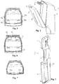
Fig. 1 is the perspective view of the integrated rear casing for cabinet and waste container -
Fig. 2 shows the front cross-section view of the unit -
Fig. 3 is the side cross-section view of the unit -
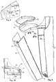
Fig. 4 is the perspective view of the top cabinet with front panel open -
Fig. 5 is a cross-section taken along line V - V inFigure 2 -
Fig. 6 .is a cross-section taken along line VI - VI inFigure 2 -
Fig. 7 is a cross-section taken along line VII - VII inFigure 2 -
Fig. 8 is a perspective view of the second design for the waste container open, partially exploded -
Fig. 9 shows the waste container in closed sate, in a perspective view -
Fig. 10 is a side cross-section view showing the assembly of liner holder frame, closing frame and adjoining components - The perspective view of
Figure 1 shows the wall-mountingstationary component 1 of the wipe dispenser and waste container unit that is the subject of the invention. It is a narrow, tall shell shape that forms the rear of the unit, best made out of a single piece of injection moulded plastic. Thestationary component 1 is a curved, designer item with three main parts. At the top, there is the rear of the wipe storage anddispenser container 2, the rear section of the waste container for usedwipes 3 is at the bottom while there is a connectingpiece 4 in the middle whose visible front surface can be used for the placement of advertising or other signs. Thecabinet 2 is for storing and dispensing the wipes that are not shown in the drawing, the interior, which is open at the front, is closed by a downward tiltingfront panel 5 connected to the rear wall of thecabinet 2 as shown inFigure 4 . Thefront panel 5 can be closed by tilting back up, when the bolts 6 shown near the top ofFigure 4 and attached to the wall of thecabinet 2 lock into theholes 7 in the narrow top of thefront panel 5 and keep it in the locked position. Opening requires a special tool not shown in the drawing which is shaped like a three-pronged fork, whose prongs can be inserted in theholes 7 so as to press the bolts 6 slightly down, until they disengage from theholes 7, allowing thefront panel 5 to be opened again. The quantity of wipes in thecabinet 2 can be seen through the narrow vertical window 8 down the centre line of thefront panel 5. - The waste container is a narrow, deep box that may be open at the top or may have a removable cover, which may have a variety of internal layouts. In the case of the first design shown
figures 2 and 3 and the accompanying cross-sections shown infigures 5-7 there is awaste container box 10 that constitutes a separate mechanical unit and which can be connected to the stationary component with a simple movement, whose shape is shown from the side by the thick line in the cross-section shown inFigure 3 . The cross-section shown infigure 3 cuts across the material of thewaste container 10, indicated by the hatched area. Essentially, thewaste container 10 fits fully into the surrounding niche in thestationary component 1, i.e. therear casing 3. The connection is clearly visible in the cross-sections shown infigures 5-7 . The front of thewaste container 10 has a sealingapron 11 attached to it as a visible cover, and in the operational position, the sealingapron 11 is connected to therear cover 3 of thestationary component 1, forming a sealed cover together. - The sealing
apron 11 is attached to the front wall of thewaste container 10 using thehidden connectors Figure 3 , whose design is shown in the cross-section inFigure 7 .Connector 13 is included in both sides. Connector 13a on the left side andconnector 13b on the right side are identical, preferably consisting of a plastic bolt and a locking eye with a release mechanism. During normal use, thesealing apron 11 and thewaste container 10 do not need to be disassembled. - The very bottom of the
stationary component 1 is angled with comb-shaped apertures 14. The bottom of the sealingapron 11 has hookedbolts 15 extending from it which fit into theapertures 14 and around whose ends thewaste container 10 and the sealingapron 11, which form a single mechanical structure, can be attached to therear cover 3. This connection interconnects to two halves of the casing seamlessly, but if the container is tilted forward, the link can be disengaged by moving the waste container upwards at an angle. - The two interlocked halves of the cover are fixed at the top partly using a magnetic connector and partly using bolts.
Figure 5 is a cross-section taken in the plane of the magnetic locking mechanism. The front and rear edges of therear cover 3 and the sealingapron 11 respectively (i.e. the sides that are in contact) are thick enough to accommodate two pairs of magnets, 16a and 16b and 17a and 17b, whose surface is level with the surface of the accommodating edges and which meet to connect to two adjoining edges with a certain amount of (releasable) force. - The seamless connection of the
waste container 10 to therear cover 3 is shown in the cross-section inFigure 6 . - The flat rear wall of the
rear cover 3, which is adjacent to the wall, has a cavity in it for asideways slide 18 that is loaded by aspring 19, with two bolts, 20a and 20b extending to the front from it, with sideways tips. The rear wall of thewaste container 10 has holes to match the bolts 19a and 19b, which the hooks ofbolts 20a and 20b catch in when thewaste container 10 is tilted all the way back. At the end of theslide 18 opposite thespring 19 therear cover 3 has threeholes 21 in its side wall (shown together inFigure 1 as well). The shapes and spacing of theholes 21 are identical to theholes 7 at the top of thefront panel 5 of thecabinet 2, so they admit the same, three-pronged tool, allowing theslide 18 to be shifted sideways, against thespring 19. The available movement is sufficient to unhook thebolts 20a and 20b from the holes in the rear wall, and after that thewaste container 10 can be tilted forwards if sufficient force is applied (to counteract the magnetic bolts). - The rear wall of the
stationary component 1 is largely in a single plane, it is flush with the wall and is attached using screws. Those go through the holes included in the rear wall for this purpose. - The
lip 23 along the front section of the top edge of thewaste container 10, as shown in the side view inFigure 3 , makes it significantly easier to install and remove it. Under thatlip 23, the front wall of thewaste container 10 and the sealingapron 11 are both recessed to provide room for grabbing the lip by hand. - The first specific design of the dispenser and collector unit that is the subject of the invention is very easy to use. The unit can be installed in gents' toilets in the space between urinals, preferably to the right of each urinal so that the top opening of the waste container is between thigh and hand height, which makes throwing the used wipe in as comfortable as possible, without having to shift position. Scale drawings of the stationary component are shown in
figures 2 and 3 , the greatest width is between 150 and 180 mm, therefore it does not require much space in the sideways direction. The depth of the unit is similar or less, so the dispenser and collector unit is not a nuisance and it may even serve as a partition from the next urinal. - The paper wipes to be used are similarly small, width between 90-120 mm, depth 50-70 mm. The
cabinet 2 can store a large number of flat, interlocking wipes, the end of the bottom wipe 24 extends forward and down through the aperture in the angled bottom of the cabinet 2 (Figure 3 ). This design makes it easy to take out wipes. After wiping, the used wipe can be dropped in the waste container with a single comfortable movement. The interior of the container is angled, used wipes drop in easily. - The
waste container 10 may only be emptied by staff as only they possess the tool required for opening thebolts 20a and b. After the bolts are undone, thewaste container 10 can be tilted forward, then removed sideways from the bottom of therear cover 3 together with the sealingapron 11 with an angled upward movement. Then it is simple to empty the container and a cleaning implement of suitable size and shape (e.g. brush or omnidirectional spraying nozzle) can be used to clean and disinfect it. -
Figures 8-10 show a second specific design whosetop cabinet 2 and general layout is identical to the first one, the difference being that instead of the permanent waste container, this one uses a disposable plastic liner made of thin foil like those in general household use that fits into the deep waste container. - In this version, the
rear cover 30 has a slightly different design, but the holes at the bottom 14 are the same. The function of the sealingapron 11 is taken over by a sealingapron 31 designed as a self-supporting front panel which has the bolts that fit into theholes 14 at the bottom (although they are not shown in the drawing) as in the previous design, i.e. the sealingapron 31 can be tilted up and down, removed and replaced in a similar manner. -
Figure 8 shows the sealingapron 31 in a tilted down (open) position, and shows the specificliner holder frame 32, which has afitting sealing frame 33. The interior of therear cover 30 is such that the sealingframe 33 and theliner holder frame 32 are supported by interior lips from underneath.Figure 8 shows that at the top of the sealingapron 31 at the front there is a suitable recessed part that allows theliner holder 32 and the sealingframe 33 to be removed and replaced with a single movement of the hand without opening the sealingapron 31. Thelip 35 is big enough to cover theliner holder 32 underneath it. The interior of therear cover 30 has therear bolt 36 shown inFigure 10 , which catches the rear edge of theliner holder frame 32 when it is tilted up, but when moved upwards at an angle, the mechanism releases automatically. The rear end of the sealingframe 33 lies atop the locked rear edge of theliner holder frame 32 and cannot be pulled out to the front. - So, in order to use the waste container, a
liner 37 of appropriate shape and size, only sketched inFigure 10 , is pulled onto the liner holder frame, folding the top edge back a little. This is essentially the manner in which all bin liners are installed. Theliner holder frame 32 and theliner 37 are placed together onto the top of the supporting lip at the top of the two-part waste container that is closed, so that the rear edge catches on therear bolt 36 then, tilting down to a horizontal position, the front edge connects withbolt 34 and theliner holder frame 32 is fixed in place. After that, the sealing frame is put in place over and around the liner holder frame with a similar angled tilting movement and when the horizontal position is reached, the whole assembly locks in place. Removal for replacement of theliner 37 is performed in the opposite order. This is very simple and can be done with one hand. Thelip 35 does not only have an aesthetic role, it also makes it simpler to remove the sealingframe 33. The sealingframe 33 is large enough to provide space for the folded back edge of the liner between itself and the liner holder frame that it surrounds. -
Figure 9 shows a sketch of the connection of the sealingapron 31 to therear cover 30. Both connector units have ahorizontal support surface components edge 38a of the sealingapron 31, while the other fits into the hole in the edge of therear cover 38b. As such, the locking components connect the two halves of the waste container at the top. At the bottom, we see the releasing connecting mechanism described for the previous design. The linked halves of the waste container do not need to be disassembled every time the liner is replaced, this is only required when the entire unit is installed or removed, or when disinfection is performed. - In view of the fact that the
liner 37 is relatively small in cross-section and very deep, after installation it has to be opened up and smoothed against the internal wall of the waste container by hand or using a manual implement. If required in order to prevent the liner going flat, flexible internal tensioning ribs, i.e. C-shaped pieces or springs may also be used. - The advantage of using the unit that is the subject of the invention is that taking and disposing of a wipe can be performed with a single hand movement, without the user having to shift position, while the unit also serves as a partition, it is hygienic and can be placed without causing any hindrance thanks to its small dimensions. The bottom of the waste container of the unit is 20 to 30 cm from the floor so it does not hinder mopping, while the top opening is between thigh and hip height for men of average height, while the bottom of the
cabinet 2 is at elbow height. This placement makes using the unit the most comfortable. For aesthetic and cost-saving purposes it is advantageous to have the cabinet and the waste collector in an integrated rear cover, but as far as use is concerned, the middle, connecting section can be left out. - It should be mentioned that the invention can also be used for other purposes as well, primarily in healthcare institutions, in all locations, where relatively small amounts of liquid need to be wiped up on a regular basis, possibly with selective collection of the waste generated. Its aesthetic design, its appearance, which may be adapted to the surrounding colour scheme, and its easy operation make it suitable for a wide range of applications.
Claims (8)
- Wipe dispenser and collector unit particularly for use in gents' toilets, with a storage cabinet (2) for batches of wipes (24), with an aperture for the bottom wipe (24), the cabinet has a wall-mounting rear cover (3) and a front panel (5) connected to it that can be tilted forward in order to open it, with those two components forming the interior of the closed wipe storage cabinet (2), with a waste container at a specific distance underneath, which also has a wall-mounting rear cover (30), whose storage space, open at the top, is defined by the rear cover (30) and the front unit that can be tilted against it, characterised by the bottom of the front unit connecting to the holes (14) at the bottom of the rear cover (30) with matching bolts (15), which can be released when the unit is tilted forward, while the front unit that forms the collection container contains of a waste container (10) that is open at the top and closed on all other sides that fits into the rear cover and a sealing apron (11) that is affixed to it using screws and which covers the front and partially the two sides of the waste container (10), whose two sides match the front edge of the rear cover (30) and is supported on it using a releasable mechanism; and the top part of the rear cover (30) having a sideways slide (18) tensioned at one end with a spring (19) with connected bolts (20a, 20b) with sideways hooks, with corresponding holes in the back wall of the waste cabinet that admit the bolts (20a, 20b), while at the end of the slide (18) opposite the spring (19) in the side of the rear cover (30) there are several holes (21) through which, using a tool whose shape fits the holes (21), the slide can be moved against the spring, which releases the bolts (20a, 20b).
- The dispenser and collector unit as claimed in claim 1, wherein the waste container (10) having a lip (23) at the front that extends outwards and down, with a recess underneath to accommodate gripping the lip (23) by hand.
- The dispenser and collector unit as claimed in claim 1, wherein the matching edges of the sealing apron (11) and the rear cover (30) having magnetic bolts in opposite positions embedded in them (16a, 16b, 17a, 17b).
- Wipe dispenser and collector unit particularly for use in gents' toilets, with a storage cabinet (2) for batches of wipes (24), with an aperture for the bottom wipe (24), the cabinet has a wall-mounting rear cover (3) and a front panel (5) connected to it that can be tilted forward in order to open it, with those two components forming the interior of the closed wipe storage cabinet (2), with a waste container at a specific distance underneath, which also has a wall-mounting rear cover (30), whose storage space, open at the top, is defined by the rear cover (30) and the front unit that can be tilted against it, characterized in that the bottom of the front unit connecting to the holes (14) at the bottom of the rear cover (30) with matching bolts (15), which can be released when the unit is tilted forward, while the front unit, that forms a collection container space for holding a liner (37), is open at the top and closed on all other sides and, the front unit fits into the rear cover (30) and has a sealing apron (31) that is affixed to it and which covers the front and partially the two sides of the waste container space, whose two sides match the front edge of the rear cover (30) and is supported on it using a releasable mechanism; and the front unit consisting of the sealing apron (31) and a removable liner holder frame (32) and locking frame (33) attached to its top, with the sealing apron (31) and the rear cover (30) having thin edges (38a, 38b) that align when the two parts are flush, which are connected by releasable locking components (39a, 39b), while the liner holder frame (32) has the liner (37) attached to it, which is actually used for collecting waste.
- The dispenser and collector unit as claimed in claim 4, wherein the top of the sealing apron (31) having a supporting recess for the liner holder frame (32), with another supporting lip on the rear cover (30), with the liner holder frame (32) fixed in place by a bolt (34) extending upwards from the front edge of the sealing apron (31) and another rear bolt extending to the front (36) from the rear cover (30), wherein the liner holder frame (32) may be removed from its place by tilting upwards and pulling at an angle.
- The dispenser and collector unit as claimed in claim 5, wherein the sealing frame (33) being placed over the liner holder frame (32) so that it covers it and it also has a lip (35) at the front that extends downwards.
- The dispenser and collector unit as claimed in claims 1 or 4, wherein the cabinet (2) and the waste collector part having an integrated rear cover (3, 30), which bridges the gap between the cabinet (2) and the waste container and which has a rear wall and two curved side walls.
- The dispenser and collector unit as claimed in claims 1 or 4, wherein the storage cabinet (2) having a bottom that is at an acute angle with the horizontal, rising from the rear towards the front and the hole (24) for leading out the edge of the lowest wipe is in the centre of that angled bottom.
Applications Claiming Priority (2)
| Application Number | Priority Date | Filing Date | Title |
|---|---|---|---|
| HU0900005A HUP0900005A2 (en) | 2009-01-06 | 2009-01-06 | Towel dispenser and collector |
| PCT/HU2010/000002 WO2010079372A1 (en) | 2009-01-06 | 2010-01-05 | Wipe dispenser and collector unit |
Publications (2)
| Publication Number | Publication Date |
|---|---|
| EP2375949A1 EP2375949A1 (en) | 2011-10-19 |
| EP2375949B1 true EP2375949B1 (en) | 2017-11-08 |
Family
ID=89988697
Family Applications (1)
| Application Number | Title | Priority Date | Filing Date |
|---|---|---|---|
| EP10701261.9A Active EP2375949B1 (en) | 2009-01-06 | 2010-01-05 | Wipe dispenser and collector unit |
Country Status (6)
| Country | Link |
|---|---|
| US (1) | US8757431B2 (en) |
| EP (1) | EP2375949B1 (en) |
| CA (1) | CA2748342C (en) |
| HU (2) | HUP0900005A2 (en) |
| MX (1) | MX2011007289A (en) |
| WO (1) | WO2010079372A1 (en) |
Families Citing this family (7)
| Publication number | Priority date | Publication date | Assignee | Title |
|---|---|---|---|---|
| US8870022B2 (en) * | 2010-05-07 | 2014-10-28 | Stacy Harfert | Diaper and wipe dispensing system |
| EP2550907A1 (en) * | 2011-07-29 | 2013-01-30 | Georgia-Pacific France | Product dispenser |
| US8561837B2 (en) * | 2011-09-16 | 2013-10-22 | Robert L. Giammanco | Wipes dispenser |
| EP3536207A1 (en) | 2018-03-05 | 2019-09-11 | Inegi - Instituto de Ciência e Inovação em Engenharia Mecânica e Engenharia Industrial | Device for personal hygiene, process and uses thereof |
| CA3131042A1 (en) * | 2019-03-11 | 2020-09-17 | Essity Hygiene And Health Aktiebolag | Dispenser for dispensing sheet products |
| US11524841B2 (en) | 2020-12-18 | 2022-12-13 | San Jamar, Inc. | Collapsible trash bin assembly |
| AT524554B9 (en) * | 2021-05-14 | 2023-06-15 | Hecht Mag Gabriele | tissue dispenser |
Family Cites Families (11)
| Publication number | Priority date | Publication date | Assignee | Title |
|---|---|---|---|---|
| US1688242A (en) | 1926-08-13 | 1928-10-16 | Lawrence Frank | Paper-towel cabinet disposer |
| US4573608A (en) * | 1982-11-29 | 1986-03-04 | Nancy Hansen | Baby changing apparatus |
| US4706845A (en) | 1986-06-23 | 1987-11-17 | Schnurer David M | Diaper dispensing and disposal unit |
| US4887767A (en) | 1988-10-21 | 1989-12-19 | Carrier Corporation | Limit switch control method for a two-stage furnace |
| US5741053A (en) * | 1997-01-21 | 1998-04-21 | Ladd Furniture, Inc. | Pedestal for utilizing computer hardware and accessories |
| US6321963B1 (en) * | 1998-02-02 | 2001-11-27 | Fort James Corporation | Sheet material dispensing apparatus and method |
| DE10237145A1 (en) | 2002-08-13 | 2004-02-26 | Robert Rattue | Device to improve hygiene at male urination stations has supply of disposable absorbent towels in container by urinal |
| JP3961416B2 (en) | 2002-12-25 | 2007-08-22 | 株式会社ジャムコ | Aircraft lavatory unit |
| US20050173285A1 (en) | 2004-02-10 | 2005-08-11 | Nellie Moncrief | Tissue dispenser and disposal unit |
| US8684228B2 (en) * | 2005-06-28 | 2014-04-01 | Handago, LLC | Sanitizing wipe dispensing system |
| WO2007035139A1 (en) * | 2005-09-20 | 2007-03-29 | Sca Hygiene Products Ab | Dispenser |
-
2009
- 2009-01-06 HU HU0900005A patent/HUP0900005A2/en unknown
-
2010
- 2010-01-05 CA CA2748342A patent/CA2748342C/en not_active Expired - Fee Related
- 2010-01-05 EP EP10701261.9A patent/EP2375949B1/en active Active
- 2010-01-05 MX MX2011007289A patent/MX2011007289A/en active IP Right Grant
- 2010-01-05 US US13/142,384 patent/US8757431B2/en not_active Expired - Fee Related
- 2010-01-05 WO PCT/HU2010/000002 patent/WO2010079372A1/en not_active Ceased
- 2010-01-05 HU HUE10701261A patent/HUE036435T2/en unknown
Non-Patent Citations (1)
| Title |
|---|
| None * |
Also Published As
| Publication number | Publication date |
|---|---|
| CA2748342C (en) | 2017-12-19 |
| US8757431B2 (en) | 2014-06-24 |
| WO2010079372A1 (en) | 2010-07-15 |
| CA2748342A1 (en) | 2010-07-15 |
| US20110266299A1 (en) | 2011-11-03 |
| HUP0900005A2 (en) | 2010-07-28 |
| WO2010079372A4 (en) | 2010-09-02 |
| HU0900005D0 (en) | 2009-03-30 |
| MX2011007289A (en) | 2011-09-09 |
| EP2375949A1 (en) | 2011-10-19 |
| HUE036435T2 (en) | 2018-07-30 |
Similar Documents
| Publication | Publication Date | Title |
|---|---|---|
| CA2748342C (en) | Wipe dispenser and collector unit | |
| US20090223992A1 (en) | Men's personal hygiene napkin dispenser and waste receptacle | |
| US20090223991A1 (en) | Men's personal hygiene napkin dispenser and waste receptacle | |
| US20090223993A1 (en) | Men's personal hygiene napkin dispenser and waste receptacle | |
| US6393627B1 (en) | Waterless toilet cabana | |
| US20090113613A1 (en) | Liner for waste elimination systems | |
| AU2014275571B2 (en) | Improvements in, or related to, sanitary containers | |
| MX2008002714A (en) | Dispensing and disposal container. | |
| CA1210901A (en) | Self-cleaning sanitary apparatus | |
| US6651260B1 (en) | Toilet tank top with easy access to drop in deodorizing discs | |
| JP2008509305A (en) | A device that can be used as either a male urinal or a stool, and a toilet equipped with the same | |
| EP1989982A2 (en) | Composite sanitary dispenser for use as a combined toilet tissue roll holder and wet wipe holder | |
| US6343845B1 (en) | Multiple bar soap storage dispenser | |
| KR101186534B1 (en) | A chamber pot with a automatic rise and fall-type seat and separable screens | |
| KR102480617B1 (en) | Urine scattering prevention device | |
| KR100818893B1 (en) | Recycle Bin with Recycle Bin | |
| KR100840929B1 (en) | Toilet seat storage box | |
| CN215477406U (en) | Foot-operated rubbish fill of wash platform opens structure | |
| CN215796088U (en) | Wall-mounted garbage can with handle | |
| US10517444B1 (en) | Paper roll dispensing device | |
| KR200303312Y1 (en) | a multipurpose wastebasket | |
| KR20250107516A (en) | Sanitary System for Men's Urinals | |
| KR20110017327A (en) | Toilet cover inside the toilet lid | |
| KR19980058820U (en) | Disposable cover removal device of toilet | |
| WO2002094012A1 (en) | Apparatus for disposing pet droppings |
Legal Events
| Date | Code | Title | Description |
|---|---|---|---|
| PUAI | Public reference made under article 153(3) epc to a published international application that has entered the european phase |
Free format text: ORIGINAL CODE: 0009012 |
|
| 17P | Request for examination filed |
Effective date: 20110715 |
|
| AK | Designated contracting states |
Kind code of ref document: A1 Designated state(s): AT BE BG CH CY CZ DE DK EE ES FI FR GB GR HR HU IE IS IT LI LT LU LV MC MK MT NL NO PL PT RO SE SI SK SM TR |
|
| AX | Request for extension of the european patent |
Extension state: RS |
|
| 17Q | First examination report despatched |
Effective date: 20160120 |
|
| GRAP | Despatch of communication of intention to grant a patent |
Free format text: ORIGINAL CODE: EPIDOSNIGR1 |
|
| INTG | Intention to grant announced |
Effective date: 20170629 |
|
| GRAS | Grant fee paid |
Free format text: ORIGINAL CODE: EPIDOSNIGR3 |
|
| GRAA | (expected) grant |
Free format text: ORIGINAL CODE: 0009210 |
|
| AK | Designated contracting states |
Kind code of ref document: B1 Designated state(s): AT BE BG CH CY CZ DE DK EE ES FI FR GB GR HR HU IE IS IT LI LT LU LV MC MK MT NL NO PL PT RO SE SI SK SM TR |
|
| AX | Request for extension of the european patent |
Extension state: RS |
|
| REG | Reference to a national code |
Ref country code: GB Ref legal event code: FG4D |
|
| REG | Reference to a national code |
Ref country code: CH Ref legal event code: EP Ref country code: AT Ref legal event code: REF Ref document number: 943351 Country of ref document: AT Kind code of ref document: T Effective date: 20171115 |
|
| REG | Reference to a national code |
Ref country code: IE Ref legal event code: FG4D |
|
| REG | Reference to a national code |
Ref country code: DE Ref legal event code: R096 Ref document number: 602010046493 Country of ref document: DE |
|
| REG | Reference to a national code |
Ref country code: FR Ref legal event code: PLFP Year of fee payment: 9 |
|
| REG | Reference to a national code |
Ref country code: NL Ref legal event code: MP Effective date: 20171108 |
|
| REG | Reference to a national code |
Ref country code: LT Ref legal event code: MG4D |
|
| REG | Reference to a national code |
Ref country code: AT Ref legal event code: MK05 Ref document number: 943351 Country of ref document: AT Kind code of ref document: T Effective date: 20171108 |
|
| PG25 | Lapsed in a contracting state [announced via postgrant information from national office to epo] |
Ref country code: LT Free format text: LAPSE BECAUSE OF FAILURE TO SUBMIT A TRANSLATION OF THE DESCRIPTION OR TO PAY THE FEE WITHIN THE PRESCRIBED TIME-LIMIT Effective date: 20171108 Ref country code: ES Free format text: LAPSE BECAUSE OF FAILURE TO SUBMIT A TRANSLATION OF THE DESCRIPTION OR TO PAY THE FEE WITHIN THE PRESCRIBED TIME-LIMIT Effective date: 20171108 Ref country code: NL Free format text: LAPSE BECAUSE OF FAILURE TO SUBMIT A TRANSLATION OF THE DESCRIPTION OR TO PAY THE FEE WITHIN THE PRESCRIBED TIME-LIMIT Effective date: 20171108 Ref country code: NO Free format text: LAPSE BECAUSE OF FAILURE TO SUBMIT A TRANSLATION OF THE DESCRIPTION OR TO PAY THE FEE WITHIN THE PRESCRIBED TIME-LIMIT Effective date: 20180208 Ref country code: SE Free format text: LAPSE BECAUSE OF FAILURE TO SUBMIT A TRANSLATION OF THE DESCRIPTION OR TO PAY THE FEE WITHIN THE PRESCRIBED TIME-LIMIT Effective date: 20171108 Ref country code: FI Free format text: LAPSE BECAUSE OF FAILURE TO SUBMIT A TRANSLATION OF THE DESCRIPTION OR TO PAY THE FEE WITHIN THE PRESCRIBED TIME-LIMIT Effective date: 20171108 |
|
| PG25 | Lapsed in a contracting state [announced via postgrant information from national office to epo] |
Ref country code: LV Free format text: LAPSE BECAUSE OF FAILURE TO SUBMIT A TRANSLATION OF THE DESCRIPTION OR TO PAY THE FEE WITHIN THE PRESCRIBED TIME-LIMIT Effective date: 20171108 Ref country code: HR Free format text: LAPSE BECAUSE OF FAILURE TO SUBMIT A TRANSLATION OF THE DESCRIPTION OR TO PAY THE FEE WITHIN THE PRESCRIBED TIME-LIMIT Effective date: 20171108 Ref country code: AT Free format text: LAPSE BECAUSE OF FAILURE TO SUBMIT A TRANSLATION OF THE DESCRIPTION OR TO PAY THE FEE WITHIN THE PRESCRIBED TIME-LIMIT Effective date: 20171108 Ref country code: IS Free format text: LAPSE BECAUSE OF FAILURE TO SUBMIT A TRANSLATION OF THE DESCRIPTION OR TO PAY THE FEE WITHIN THE PRESCRIBED TIME-LIMIT Effective date: 20180308 Ref country code: BG Free format text: LAPSE BECAUSE OF FAILURE TO SUBMIT A TRANSLATION OF THE DESCRIPTION OR TO PAY THE FEE WITHIN THE PRESCRIBED TIME-LIMIT Effective date: 20180208 Ref country code: GR Free format text: LAPSE BECAUSE OF FAILURE TO SUBMIT A TRANSLATION OF THE DESCRIPTION OR TO PAY THE FEE WITHIN THE PRESCRIBED TIME-LIMIT Effective date: 20180209 |
|
| REG | Reference to a national code |
Ref country code: HU Ref legal event code: AG4A Ref document number: E036435 Country of ref document: HU |
|
| PG25 | Lapsed in a contracting state [announced via postgrant information from national office to epo] |
Ref country code: CZ Free format text: LAPSE BECAUSE OF FAILURE TO SUBMIT A TRANSLATION OF THE DESCRIPTION OR TO PAY THE FEE WITHIN THE PRESCRIBED TIME-LIMIT Effective date: 20171108 Ref country code: SK Free format text: LAPSE BECAUSE OF FAILURE TO SUBMIT A TRANSLATION OF THE DESCRIPTION OR TO PAY THE FEE WITHIN THE PRESCRIBED TIME-LIMIT Effective date: 20171108 Ref country code: DK Free format text: LAPSE BECAUSE OF FAILURE TO SUBMIT A TRANSLATION OF THE DESCRIPTION OR TO PAY THE FEE WITHIN THE PRESCRIBED TIME-LIMIT Effective date: 20171108 Ref country code: CY Free format text: LAPSE BECAUSE OF FAILURE TO SUBMIT A TRANSLATION OF THE DESCRIPTION OR TO PAY THE FEE WITHIN THE PRESCRIBED TIME-LIMIT Effective date: 20171108 Ref country code: EE Free format text: LAPSE BECAUSE OF FAILURE TO SUBMIT A TRANSLATION OF THE DESCRIPTION OR TO PAY THE FEE WITHIN THE PRESCRIBED TIME-LIMIT Effective date: 20171108 |
|
| REG | Reference to a national code |
Ref country code: DE Ref legal event code: R097 Ref document number: 602010046493 Country of ref document: DE |
|
| PG25 | Lapsed in a contracting state [announced via postgrant information from national office to epo] |
Ref country code: PL Free format text: LAPSE BECAUSE OF FAILURE TO SUBMIT A TRANSLATION OF THE DESCRIPTION OR TO PAY THE FEE WITHIN THE PRESCRIBED TIME-LIMIT Effective date: 20171108 Ref country code: RO Free format text: LAPSE BECAUSE OF FAILURE TO SUBMIT A TRANSLATION OF THE DESCRIPTION OR TO PAY THE FEE WITHIN THE PRESCRIBED TIME-LIMIT Effective date: 20171108 Ref country code: IT Free format text: LAPSE BECAUSE OF FAILURE TO SUBMIT A TRANSLATION OF THE DESCRIPTION OR TO PAY THE FEE WITHIN THE PRESCRIBED TIME-LIMIT Effective date: 20171108 Ref country code: SM Free format text: LAPSE BECAUSE OF FAILURE TO SUBMIT A TRANSLATION OF THE DESCRIPTION OR TO PAY THE FEE WITHIN THE PRESCRIBED TIME-LIMIT Effective date: 20171108 |
|
| REG | Reference to a national code |
Ref country code: CH Ref legal event code: PL |
|
| PLBE | No opposition filed within time limit |
Free format text: ORIGINAL CODE: 0009261 |
|
| STAA | Information on the status of an ep patent application or granted ep patent |
Free format text: STATUS: NO OPPOSITION FILED WITHIN TIME LIMIT |
|
| PGFP | Annual fee paid to national office [announced via postgrant information from national office to epo] |
Ref country code: HU Payment date: 20180302 Year of fee payment: 9 |
|
| 26N | No opposition filed |
Effective date: 20180809 |
|
| PG25 | Lapsed in a contracting state [announced via postgrant information from national office to epo] |
Ref country code: LU Free format text: LAPSE BECAUSE OF NON-PAYMENT OF DUE FEES Effective date: 20180105 |
|
| REG | Reference to a national code |
Ref country code: IE Ref legal event code: MM4A |
|
| REG | Reference to a national code |
Ref country code: BE Ref legal event code: MM Effective date: 20180131 |
|
| PG25 | Lapsed in a contracting state [announced via postgrant information from national office to epo] |
Ref country code: BE Free format text: LAPSE BECAUSE OF NON-PAYMENT OF DUE FEES Effective date: 20180131 Ref country code: CH Free format text: LAPSE BECAUSE OF NON-PAYMENT OF DUE FEES Effective date: 20180131 Ref country code: SI Free format text: LAPSE BECAUSE OF FAILURE TO SUBMIT A TRANSLATION OF THE DESCRIPTION OR TO PAY THE FEE WITHIN THE PRESCRIBED TIME-LIMIT Effective date: 20171108 Ref country code: LI Free format text: LAPSE BECAUSE OF NON-PAYMENT OF DUE FEES Effective date: 20180131 |
|
| PG25 | Lapsed in a contracting state [announced via postgrant information from national office to epo] |
Ref country code: IE Free format text: LAPSE BECAUSE OF NON-PAYMENT OF DUE FEES Effective date: 20180105 |
|
| PGFP | Annual fee paid to national office [announced via postgrant information from national office to epo] |
Ref country code: FR Payment date: 20190124 Year of fee payment: 10 Ref country code: GB Payment date: 20190121 Year of fee payment: 10 Ref country code: DE Payment date: 20190123 Year of fee payment: 10 |
|
| PG25 | Lapsed in a contracting state [announced via postgrant information from national office to epo] |
Ref country code: MC Free format text: LAPSE BECAUSE OF FAILURE TO SUBMIT A TRANSLATION OF THE DESCRIPTION OR TO PAY THE FEE WITHIN THE PRESCRIBED TIME-LIMIT Effective date: 20171108 |
|
| PG25 | Lapsed in a contracting state [announced via postgrant information from national office to epo] |
Ref country code: HU Free format text: LAPSE BECAUSE OF NON-PAYMENT OF DUE FEES Effective date: 20190106 |
|
| PG25 | Lapsed in a contracting state [announced via postgrant information from national office to epo] |
Ref country code: MT Free format text: LAPSE BECAUSE OF NON-PAYMENT OF DUE FEES Effective date: 20180105 |
|
| PG25 | Lapsed in a contracting state [announced via postgrant information from national office to epo] |
Ref country code: TR Free format text: LAPSE BECAUSE OF FAILURE TO SUBMIT A TRANSLATION OF THE DESCRIPTION OR TO PAY THE FEE WITHIN THE PRESCRIBED TIME-LIMIT Effective date: 20171108 |
|
| PG25 | Lapsed in a contracting state [announced via postgrant information from national office to epo] |
Ref country code: PT Free format text: LAPSE BECAUSE OF FAILURE TO SUBMIT A TRANSLATION OF THE DESCRIPTION OR TO PAY THE FEE WITHIN THE PRESCRIBED TIME-LIMIT Effective date: 20171108 |
|
| PG25 | Lapsed in a contracting state [announced via postgrant information from national office to epo] |
Ref country code: MK Free format text: LAPSE BECAUSE OF NON-PAYMENT OF DUE FEES Effective date: 20171108 |
|
| REG | Reference to a national code |
Ref country code: DE Ref legal event code: R119 Ref document number: 602010046493 Country of ref document: DE |
|
| GBPC | Gb: european patent ceased through non-payment of renewal fee |
Effective date: 20200105 |
|
| PG25 | Lapsed in a contracting state [announced via postgrant information from national office to epo] |
Ref country code: FR Free format text: LAPSE BECAUSE OF NON-PAYMENT OF DUE FEES Effective date: 20200131 Ref country code: DE Free format text: LAPSE BECAUSE OF NON-PAYMENT OF DUE FEES Effective date: 20200801 Ref country code: GB Free format text: LAPSE BECAUSE OF NON-PAYMENT OF DUE FEES Effective date: 20200105 |