EP2375863A2 - External electrical-control lamp with improved structure - Google Patents
External electrical-control lamp with improved structure Download PDFInfo
- Publication number
- EP2375863A2 EP2375863A2 EP11150499A EP11150499A EP2375863A2 EP 2375863 A2 EP2375863 A2 EP 2375863A2 EP 11150499 A EP11150499 A EP 11150499A EP 11150499 A EP11150499 A EP 11150499A EP 2375863 A2 EP2375863 A2 EP 2375863A2
- Authority
- EP
- European Patent Office
- Prior art keywords
- light
- emitting diode
- lamp
- circuit
- power box
- Prior art date
- Legal status (The legal status is an assumption and is not a legal conclusion. Google has not performed a legal analysis and makes no representation as to the accuracy of the status listed.)
- Withdrawn
Links
Images


Classifications
-
- F—MECHANICAL ENGINEERING; LIGHTING; HEATING; WEAPONS; BLASTING
- F21—LIGHTING
- F21V—FUNCTIONAL FEATURES OR DETAILS OF LIGHTING DEVICES OR SYSTEMS THEREOF; STRUCTURAL COMBINATIONS OF LIGHTING DEVICES WITH OTHER ARTICLES, NOT OTHERWISE PROVIDED FOR
- F21V23/00—Arrangement of electric circuit elements in or on lighting devices
- F21V23/04—Arrangement of electric circuit elements in or on lighting devices the elements being switches
-
- F—MECHANICAL ENGINEERING; LIGHTING; HEATING; WEAPONS; BLASTING
- F21—LIGHTING
- F21K—NON-ELECTRIC LIGHT SOURCES USING LUMINESCENCE; LIGHT SOURCES USING ELECTROCHEMILUMINESCENCE; LIGHT SOURCES USING CHARGES OF COMBUSTIBLE MATERIAL; LIGHT SOURCES USING SEMICONDUCTOR DEVICES AS LIGHT-GENERATING ELEMENTS; LIGHT SOURCES NOT OTHERWISE PROVIDED FOR
- F21K9/00—Light sources using semiconductor devices as light-generating elements, e.g. using light-emitting diodes [LED] or lasers
- F21K9/20—Light sources comprising attachment means
- F21K9/23—Retrofit light sources for lighting devices with a single fitting for each light source, e.g. for substitution of incandescent lamps with bayonet or threaded fittings
- F21K9/233—Retrofit light sources for lighting devices with a single fitting for each light source, e.g. for substitution of incandescent lamps with bayonet or threaded fittings specially adapted for generating a spot light distribution, e.g. for substitution of reflector lamps
-
- H—ELECTRICITY
- H05—ELECTRIC TECHNIQUES NOT OTHERWISE PROVIDED FOR
- H05B—ELECTRIC HEATING; ELECTRIC LIGHT SOURCES NOT OTHERWISE PROVIDED FOR; CIRCUIT ARRANGEMENTS FOR ELECTRIC LIGHT SOURCES, IN GENERAL
- H05B45/00—Circuit arrangements for operating light-emitting diodes [LED]
- H05B45/30—Driver circuits
- H05B45/345—Current stabilisation; Maintaining constant current
-
- H—ELECTRICITY
- H05—ELECTRIC TECHNIQUES NOT OTHERWISE PROVIDED FOR
- H05B—ELECTRIC HEATING; ELECTRIC LIGHT SOURCES NOT OTHERWISE PROVIDED FOR; CIRCUIT ARRANGEMENTS FOR ELECTRIC LIGHT SOURCES, IN GENERAL
- H05B45/00—Circuit arrangements for operating light-emitting diodes [LED]
- H05B45/30—Driver circuits
- H05B45/355—Power factor correction [PFC]; Reactive power compensation
-
- F—MECHANICAL ENGINEERING; LIGHTING; HEATING; WEAPONS; BLASTING
- F21—LIGHTING
- F21V—FUNCTIONAL FEATURES OR DETAILS OF LIGHTING DEVICES OR SYSTEMS THEREOF; STRUCTURAL COMBINATIONS OF LIGHTING DEVICES WITH OTHER ARTICLES, NOT OTHERWISE PROVIDED FOR
- F21V29/00—Protecting lighting devices from thermal damage; Cooling or heating arrangements specially adapted for lighting devices or systems
- F21V29/50—Cooling arrangements
- F21V29/70—Cooling arrangements characterised by passive heat-dissipating elements, e.g. heat-sinks
- F21V29/74—Cooling arrangements characterised by passive heat-dissipating elements, e.g. heat-sinks with fins or blades
- F21V29/77—Cooling arrangements characterised by passive heat-dissipating elements, e.g. heat-sinks with fins or blades with essentially identical diverging planar fins or blades, e.g. with fan-like or star-like cross-section
- F21V29/773—Cooling arrangements characterised by passive heat-dissipating elements, e.g. heat-sinks with fins or blades with essentially identical diverging planar fins or blades, e.g. with fan-like or star-like cross-section the planes containing the fins or blades having the direction of the light emitting axis
-
- F—MECHANICAL ENGINEERING; LIGHTING; HEATING; WEAPONS; BLASTING
- F21—LIGHTING
- F21Y—INDEXING SCHEME ASSOCIATED WITH SUBCLASSES F21K, F21L, F21S and F21V, RELATING TO THE FORM OR THE KIND OF THE LIGHT SOURCES OR OF THE COLOUR OF THE LIGHT EMITTED
- F21Y2115/00—Light-generating elements of semiconductor light sources
- F21Y2115/10—Light-emitting diodes [LED]
-
- H—ELECTRICITY
- H05—ELECTRIC TECHNIQUES NOT OTHERWISE PROVIDED FOR
- H05B—ELECTRIC HEATING; ELECTRIC LIGHT SOURCES NOT OTHERWISE PROVIDED FOR; CIRCUIT ARRANGEMENTS FOR ELECTRIC LIGHT SOURCES, IN GENERAL
- H05B45/00—Circuit arrangements for operating light-emitting diodes [LED]
- H05B45/30—Driver circuits
- H05B45/31—Phase-control circuits
Definitions
- the present invention relates to a lamp structure, and more particularly to an external electrical-control lamp with improved structure that can provide an energy-saving operation, reduce temperature of electronic components, and increase product reliability.
- LEDs were used to indication or advertisement applications. With the tremendous development of science and technology, LEDs play a significant role in illumination, backlight, and display applications. Until the introduction of white LEDs, a major breakthrough in lighting applications occurs. Because LEDs present many advantages including lower energy consumption, longer lifetime, and maintenance free, the lamps of using LEDs are highly interested and popularized by world governments and companies.
- the integrated light-emitting diode has following disadvantages:
- the power control circuit of driving the light-emitting diodes has to be installed in the light-emitting diode lamp. It should also be added that the lighting efficiency of the existing light-emitting diode is relatively lower. Accordingly, when the light-emitting diodes are operated, much electrical consumption would be converted into heat energy. However, the high-temperature situation would significantly influence reliability and stability of the light-emitting diodes and other electronic components.
- an external electrical-control lamp with improved structure is disclosed to provide an energy-saving operation, reduce temperature of electronic components, and increase product reliability.
- the external electrical-control lamp with improved structure includes a light-emitting diode lamp, an external power box and a dimmer.
- the light-emitting diode lamp has a circuit board, at least one light-emitting diode, a thermal module, and a rectifying circuit.
- the light-emitting diode is installed on the circuit board.
- the thermal module provides a heat-dissipating function to the light-emitting diode.
- the rectifying circuit provides a rectified power to the light-emitting diode.
- the external power box has an AC-to-DC conversion circuit, a voltage/current feedback circuit, an isolated transformer, a constant-current output circuit, a power factor correction circuit, and a dimming control loop.
- One end of the external power box is electrically connected to the rectifying circuit of the light-emitting diode lamp, thus providing electricity power to the light-emitting diode lamp.
- the light-emitting diode lamp has light-emitting and heat-dissipating functions and the external power box can provide the require power for the light-emitting diode lamp.
- the light-emitting diode lamp or the external power box malfunctions, it only needs to replace the light-emitting diode lamp or the external power box, that is, it does not need to discard the entire light-emitting diode module. This would avoid waste of the usable components to meet the requirements of environmental protection.
- the higher temperature which is produced from lighting the light-emitting diodes, would decrease the lifetime and reliability of the power control circuit because of volatilization of the electrolyte solution of electrolytic capacitors thereof.
- the interior temperature of the light-emitting diode lamp could effectively decrease when the external power box is used.
- a rectifying circuit installed in the light-emitting diode lamp is provided to rectified power to the light-emitting diode.
- interior temperature of the light-emitting diode lamp could effectively decrease because of increasing interior space of the light-emitting diode lamp (without installing other electrical control components), thus increasing the lifetime and reliability thereof.
- variable resistor of the dimmer can be adjusted to adjust the brightness of the light-emitting diode.
- Fig. 1 , Fig. 2 , and Fig. 3 are a perspective view, an exploded perspective view, and a block diagram of a preferred embodiment according to the present invention, respectively.
- An external electrical-control lamp with improved structure includes a light-emitting diode lamp 1, an external power box 2, and a dimmer 4.
- the light-emitting diode lamp 1 has a circuit board 11, at least one light-emitting diode 12, a thermal module 13, a rectifying circuit 14, and a lamp housing 15.
- the light-emitting diode 12 is installed on the circuit board 11.
- the thermal module 13 provides a heat-dissipating function to the light-emitting diode 12.
- the rectifying circuit 14 provides a rectified power to the light-emitting diode 12.
- the rectifying circuit 14 is a bridge diode rectifying circuit 14.
- the light-emitting diode lamp 1 is held on a lamp housing 15.
- the dimmer 4 is electrically connected between the external power box 2 and the utility power 3 to adjust the brightness of the light-emitting diode 12.
- the dimmer 4 is a phase-control dimmer. That is, the dimmer 4 has a phase-control circuit (not shown) which is composed of a diode AC switch (DIAC) and a triode AC semiconductor switch (TRIAC).
- the operation of the phase-control circuit is described as follows.
- the DIAC is a trigger diode that conducts current only after its breakdown voltage has been reached momentarily. When this occurs, a pulse signal is produced. The pulse signal is provided to trigger the TRIAC to implement the phase-control dimming.
- the phase-control circuit further has a variable resistor. By adjusting the variable resistor, the conduction angles of the DIAC and the TRIAC are controlled to adjust the brightness of the light-emitting diode 12.
- the external power box 2 has an AC-to-DC conversion circuit 21, a voltage/current feedback circuit 22, an isolated transformer 23, a constant-current output circuit 24, a power factor correction circuit 25, and a dimming control loop 26.
- one end of the external power box 2 is electrically connected to rectifying circuit 14 of the light-emitting diode lamp 1, thus providing electricity power to the light-emitting diode lamp 1.
- the rectifying circuit 14 has a pin 141, and the pin 141 is electrically connected to the external power box 2.
- the other end of the external power box 2 is electrically connected to one end of the dimmer 4.
- the external electrical-control lamp has an AC-to-DC conversion circuit 21, a voltage/current feedback circuit 22, an isolated transformer 23, a constant-current output circuit 24, a power factor correction circuit 25, and a dimming control loop 26.
- the AC-to-DC conversion circuit 21, the voltage/current feedback circuit 22, the isolated transformer 23, the constant-current output circuit 24, the power factor correction circuit 25, and the dimming control loop 26 are properly electrically connected to each other, thus providing electrical functions.
- the utility power 3 is delivered to the external power box 2 through the dimmer 4.
- the dimmer 4 delivers the utility power 3 to one end of the external power box 2, and then the utility power 3 is delivered from the other end of the external power box 2 to the light-emitting diode lamp 1, thus providing electricity power to the light-emitting diode lamp 1.
- the rectifying circuit 14 of the light-emitting diode lamp 1 rectifies the received utility power 3 to provide a rectified power to the light-emitting diode 12.
- the dimming control loop 26 adjusts the output energy to the load (namely, the light-emitting diode 12) according to the adjusted resistor value of the variable resistor (namely, the adjusted conduction angles of the DIAC and the TRIAC). That is, when the variable resistor is adjusted to degrade the brightness of the light-emitting diode 12, the dimming control loop 26 controls and delivers the degraded voltage and current to the output end through the isolated transformer 23, thus reducing the output energy.
- the light-emitting diode lamp 1 does not require any power control circuit because the light-emitting diode lamp 1 has the rectifying circuit 14. Thus, the light-emitting diode lamp 1 does not judge the polarity of the applied power when the utility power 3 is delivered to the light-emitting diode lamp 1 through the external power box 2.
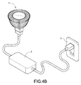
- Fig. 4B is a schematic view of another embodiment.
- the dimmer 4 is optional device based on the external electrical-control lamp and the dimmer 4 is whether used according to the user's demand.
- the utility power 3 is electrically connected to one end of the external power box 2 and the other end of the external power box 2 is electrically connected to the light-emitting diode lamp 1, thus providing electricity power to the light-emitting diode lamp 1. Because the operation of the light-emitting diode lamp 1 is the same as stated above, the detail description is omitted here for conciseness.
- the amount of the light-emitting diodes 12 is not limited to only one. Whether the light-emitting diodes 12 are connected in series or in parallel, the external power box 2 can be directly connected to the light-emitting diode lamp 1. The light-emitting diodes 12 can be driven by a high voltage or also a low voltage produced from the external power box 2.
Landscapes
- Engineering & Computer Science (AREA)
- General Engineering & Computer Science (AREA)
- Physics & Mathematics (AREA)
- Microelectronics & Electronic Packaging (AREA)
- Optics & Photonics (AREA)
- Circuit Arrangement For Electric Light Sources In General (AREA)
Abstract
Description
- The present invention relates to a lamp structure, and more particularly to an external electrical-control lamp with improved structure that can provide an energy-saving operation, reduce temperature of electronic components, and increase product reliability.
- Early days, LEDs were used to indication or advertisement applications. With the tremendous development of science and technology, LEDs play a significant role in illumination, backlight, and display applications. Until the introduction of white LEDs, a major breakthrough in lighting applications occurs. Because LEDs present many advantages including lower energy consumption, longer lifetime, and maintenance free, the lamps of using LEDs are highly interested and popularized by world governments and companies.
- Today, a light-emitting diode lamp integrated into the traditional halogen lamp is developed. Hence, the conventional connectors of the halogen lamp would not be discarded and the hot pluggable light-emitting diode lamp can directly replace the halogen lamp.
- However, the integrated light-emitting diode has following disadvantages:
- Because the light-emitting diode lamp has sharing connectors to the halogen lamp, the power control circuit of driving the light-emitting diodes has to be installed in the light-emitting diode lamp. It should also be added that the lighting efficiency of the existing light-emitting diode is relatively lower. Accordingly, when the light-emitting diodes are operated, much electrical consumption would be converted into heat energy. However, the high-temperature situation would significantly influence reliability and stability of the light-emitting diodes and other electronic components.
- In addition, it is needs to discard the entire power control circuit or the light-emitting diode lamp when the power control circuit or the light-emitting diode lamp malfunctions. This would cause waste of the usable components to raise the issues of environmental protection.
- In order to overcome the above-mentioned disadvantages, an external electrical-control lamp with improved structure is disclosed to provide an energy-saving operation, reduce temperature of electronic components, and increase product reliability.
- In order to achieve the above-mentioned objectives, the external electrical-control lamp with improved structure includes a light-emitting diode lamp, an external power box and a dimmer. The light-emitting diode lamp has a circuit board, at least one light-emitting diode, a thermal module, and a rectifying circuit. The light-emitting diode is installed on the circuit board. The thermal module provides a heat-dissipating function to the light-emitting diode. The rectifying circuit provides a rectified power to the light-emitting diode.
- The external power box has an AC-to-DC conversion circuit, a voltage/current feedback circuit, an isolated transformer, a constant-current output circuit, a power factor correction circuit, and a dimming control loop.
- One end of the external power box is electrically connected to the rectifying circuit of the light-emitting diode lamp, thus providing electricity power to the light-emitting diode lamp.
- In particular, the light-emitting diode lamp has light-emitting and heat-dissipating functions and the external power box can provide the require power for the light-emitting diode lamp. When the light-emitting diode lamp or the external power box malfunctions, it only needs to replace the light-emitting diode lamp or the external power box, that is, it does not need to discard the entire light-emitting diode module. This would avoid waste of the usable components to meet the requirements of environmental protection.
- In general, when the power control circuit is integrated into light-emitting diode lamp, the higher temperature, which is produced from lighting the light-emitting diodes, would decrease the lifetime and reliability of the power control circuit because of volatilization of the electrolyte solution of electrolytic capacitors thereof. Hence, the interior temperature of the light-emitting diode lamp could effectively decrease when the external power box is used.
- Furthermore, a rectifying circuit installed in the light-emitting diode lamp is provided to rectified power to the light-emitting diode. Hence, interior temperature of the light-emitting diode lamp could effectively decrease because of increasing interior space of the light-emitting diode lamp (without installing other electrical control components), thus increasing the lifetime and reliability thereof.
- In addition, the value of the variable resistor of the dimmer can be adjusted to adjust the brightness of the light-emitting diode.
- It is to be understood that both the foregoing general description and the following detailed description are exemplary, and are intended to provide further explanation of the invention as claimed. Other advantages and features of the invention will be apparent from the following description, drawings and claims.
- The features of the invention believed to be novel are set forth with particularity in the appended claims. The invention itself, however, may be best understood by reference to the following detailed description of the invention, which describes an exemplary embodiment of the invention, taken in conjunction with the accompanying drawings, in which:
-
Fig. 1 is a perspective view of a preferred embodiment according to the present invention; -
Fig. 2 is an exploded perspective view of the preferred embodiment; -
Fig. 3 is a block diagram of the preferred embodiment; -
Fig. 4A is a schematic view of the preferred embodiment; and -
Fig. 4B is a schematic view of another embodiment. - Reference will now be made to the drawing figures to describe the present invention in detail.
- Reference is made to
Fig. 1 ,Fig. 2 , andFig. 3 which are a perspective view, an exploded perspective view, and a block diagram of a preferred embodiment according to the present invention, respectively. - An external electrical-control lamp with improved structure includes a light-emitting
diode lamp 1, anexternal power box 2, and adimmer 4. The light-emitting diode lamp 1 has acircuit board 11, at least one light-emitting diode 12, athermal module 13, a rectifyingcircuit 14, and alamp housing 15. The light-emitting diode 12 is installed on thecircuit board 11. Thethermal module 13 provides a heat-dissipating function to the light-emittingdiode 12. The rectifyingcircuit 14 provides a rectified power to the light-emittingdiode 12. In particular, the rectifyingcircuit 14 is a bridge diode rectifyingcircuit 14. In addition, the light-emittingdiode lamp 1 is held on alamp housing 15. - The
dimmer 4 is electrically connected between theexternal power box 2 and theutility power 3 to adjust the brightness of the light-emittingdiode 12. Thedimmer 4 is a phase-control dimmer. That is, thedimmer 4 has a phase-control circuit (not shown) which is composed of a diode AC switch (DIAC) and a triode AC semiconductor switch (TRIAC). The operation of the phase-control circuit is described as follows. The DIAC is a trigger diode that conducts current only after its breakdown voltage has been reached momentarily. When this occurs, a pulse signal is produced. The pulse signal is provided to trigger the TRIAC to implement the phase-control dimming. The phase-control circuit further has a variable resistor. By adjusting the variable resistor, the conduction angles of the DIAC and the TRIAC are controlled to adjust the brightness of the light-emittingdiode 12. - The
external power box 2 has an AC-to-DC conversion circuit 21, a voltage/current feedback circuit 22, anisolated transformer 23, a constant-current output circuit 24, a powerfactor correction circuit 25, and adimming control loop 26. In particular, one end of theexternal power box 2 is electrically connected to rectifyingcircuit 14 of the light-emittingdiode lamp 1, thus providing electricity power to the light-emittingdiode lamp 1. In particular, the rectifyingcircuit 14 has apin 141, and thepin 141 is electrically connected to theexternal power box 2. The other end of theexternal power box 2 is electrically connected to one end of thedimmer 4. - The detailed description of the external electrical-control lamp according to the above-mentioned structure and circuit design will be made as follows. Reference is further made to
Fig. 4A which is a schematic view of the preferred embodiment. Theexternal power box 2 has an AC-to-DC conversion circuit 21, a voltage/current feedback circuit 22, anisolated transformer 23, a constant-current output circuit 24, a powerfactor correction circuit 25, and adimming control loop 26. In particular, the AC-to-DC conversion circuit 21, the voltage/current feedback circuit 22, theisolated transformer 23, the constant-current output circuit 24, the powerfactor correction circuit 25, and the dimmingcontrol loop 26 are properly electrically connected to each other, thus providing electrical functions. Theutility power 3 is delivered to theexternal power box 2 through thedimmer 4. Thedimmer 4 delivers theutility power 3 to one end of theexternal power box 2, and then theutility power 3 is delivered from the other end of theexternal power box 2 to the light-emittingdiode lamp 1, thus providing electricity power to the light-emittingdiode lamp 1. In addition, the rectifyingcircuit 14 of the light-emittingdiode lamp 1 rectifies the receivedutility power 3 to provide a rectified power to the light-emittingdiode 12. - In particular, the dimming
control loop 26 adjusts the output energy to the load (namely, the light-emitting diode 12) according to the adjusted resistor value of the variable resistor (namely, the adjusted conduction angles of the DIAC and the TRIAC). That is, when the variable resistor is adjusted to degrade the brightness of the light-emittingdiode 12, the dimmingcontrol loop 26 controls and delivers the degraded voltage and current to the output end through theisolated transformer 23, thus reducing the output energy. - In addition, the light-emitting
diode lamp 1 does not require any power control circuit because the light-emittingdiode lamp 1 has the rectifyingcircuit 14. Thus, the light-emittingdiode lamp 1 does not judge the polarity of the applied power when theutility power 3 is delivered to the light-emittingdiode lamp 1 through theexternal power box 2. - Reference is further made to
Fig. 4B which is a schematic view of another embodiment. Thedimmer 4 is optional device based on the external electrical-control lamp and thedimmer 4 is whether used according to the user's demand. As shown inFig. 4B , theutility power 3 is electrically connected to one end of theexternal power box 2 and the other end of theexternal power box 2 is electrically connected to the light-emittingdiode lamp 1, thus providing electricity power to the light-emittingdiode lamp 1. Because the operation of the light-emittingdiode lamp 1 is the same as stated above, the detail description is omitted here for conciseness. - Furthermore, the amount of the light-emitting
diodes 12 is not limited to only one. Whether the light-emittingdiodes 12 are connected in series or in parallel, theexternal power box 2 can be directly connected to the light-emittingdiode lamp 1. The light-emittingdiodes 12 can be driven by a high voltage or also a low voltage produced from theexternal power box 2. - In conclusion, the present invention has following advantages:
- 1. When the light-emitting
diode lamp 1 or theexternal power box 2 malfunctions, it only needs to replace the light-emittingdiode lamp 1 or theexternal power box 2, that is, it does not need to discard the entire light-emitting diode module. This would avoid waste of the usable components to meet the requirements of environmental protection. - 2. The power control circuits are installed in the
external power box 2 to effectively reduce the temperature around the electronic components. - 3. The interior temperature of the light-emitting
diode lamp 1 could effectively decrease because of increasing interior space of the light-emittingdiode lamp 1, thus increasing the lifetime and reliability thereof. - 4. Because the unrectified power is delivered to the light-emitting
diode lamp 1 through theexternal power box 2, the light-emittingdiode lamp 1 can be considered as the non-polarity lamp to increase of use compatibility. - 5. Whether the light-emitting
diodes 12 are connected in series or in parallel, theexternal power box 2 can be directly connected to the light-emittingdiode lamp 1. - 6. The light-emitting
diode lamp 1 can be used to substitute the traditional halogen lamp to realize the energy saving. - 7. By adjusting the variable resistor of the
dimmer 4, the conduction angles of the DIAC and the TRIAC are control to adjust the brightness of the light-emittingdiode 12. - 8. The light-emitting
diodes 12 can be driven by a high voltage or also a low voltage to increase the compatibility of the power supply for the light-emittingdiode lamp 1.
Claims (8)
- An external electrical-control lamp with improved structure comprising:a light-emitting diode lamp (1) having:a circuit board (11);at least one light-emitting diode (12) installed on the circuit board (11);a thermal module (13) providing a heat-dissipating function to the light-emitting diode (12);
anda rectifying circuit (14) providing a rectified power to the light-emitting diode (12); andan external power box (2) having an AC-to-DC conversion circuit (21), a voltage/current feedback circuit (22), an isolated transformer (23), a constant-current output circuit (24), and a power factor correction circuit (25);wherein one end of the external power box (2) is electrically connected to the rectifying circuit (14) of the light-emitting diode lamp (1), thus providing electricity power to the light-emitting diode lamp (1). - The external electrical-control lamp in claim 1, wherein the rectifying circuit (14) is a bridge diode rectifying circuit.
- The external electrical-control lamp in claim 1, wherein the light-emitting diode lamp (1) is held on a lamp housing.
- The external electrical-control lamp in claim 1, wherein the rectifying circuit (14) has a pin (141), and the pin (141) is electrically connected to the external power box (2).
- The external electrical-control lamp in claim 1, further comprising:a dimmer (4) electrically connected between the external power box (2) and the utility power (3) to adjust the brightness of the light-emitting diode (12).
- The external electrical-control lamp in claim 1, wherein the external power box (2) further has a dimming control loop (26).
- The external electrical-control lamp in claim 1, wherein the other end of the external power box (2) is electrically connected to the dimmer (4).
- The external electrical-control lamp in claim 5, wherein the dimmer (4) has a phase-control circuit which is composed of a diode AC switch (DIAC),a triode AC semiconductor switch (TRIAC), and a variable resistor.
Applications Claiming Priority (1)
| Application Number | Priority Date | Filing Date | Title |
|---|---|---|---|
| TW099206255U TWM396594U (en) | 2010-04-09 | 2010-04-09 | Structural improvement for externally-connected type electrical control lamp |
Publications (2)
| Publication Number | Publication Date |
|---|---|
| EP2375863A2 true EP2375863A2 (en) | 2011-10-12 |
| EP2375863A3 EP2375863A3 (en) | 2012-06-20 |
Family
ID=44167985
Family Applications (1)
| Application Number | Title | Priority Date | Filing Date |
|---|---|---|---|
| EP11150499A Withdrawn EP2375863A3 (en) | 2010-04-09 | 2011-01-10 | External electrical-control lamp with improved structure |
Country Status (3)
| Country | Link |
|---|---|
| US (1) | US8390202B2 (en) |
| EP (1) | EP2375863A3 (en) |
| TW (1) | TWM396594U (en) |
Families Citing this family (3)
| Publication number | Priority date | Publication date | Assignee | Title |
|---|---|---|---|---|
| CN107314305A (en) * | 2017-06-29 | 2017-11-03 | 惠州市超频三光电科技有限公司 | Light fixture, power supply and its power pack |
| KR20210031226A (en) | 2019-09-11 | 2021-03-19 | 주식회사 엘지화학 | Apparatus and method for managing battery |
| CN113966036A (en) * | 2021-08-13 | 2022-01-21 | 埃米尔智能技术(上海)有限公司 | Integral type down lamp with power storehouse |
Family Cites Families (7)
| Publication number | Priority date | Publication date | Assignee | Title |
|---|---|---|---|---|
| US5821699A (en) * | 1994-09-30 | 1998-10-13 | Pacific Scientific | Ballast circuit for fluorescent lamps |
| US6181086B1 (en) * | 1998-04-27 | 2001-01-30 | Jrs Technology Inc. | Electronic ballast with embedded network micro-controller |
| US7646029B2 (en) * | 2004-07-08 | 2010-01-12 | Philips Solid-State Lighting Solutions, Inc. | LED package methods and systems |
| US20080122364A1 (en) * | 2006-11-27 | 2008-05-29 | Mcclellan Thomas | Light device having LED illumination and an electronic circuit board |
| US8502454B2 (en) * | 2008-02-08 | 2013-08-06 | Innosys, Inc | Solid state semiconductor LED replacement for fluorescent lamps |
| WO2010024977A1 (en) * | 2008-08-25 | 2010-03-04 | Illinois Tool Works Inc. | Driving circuit for high-powered light emitting diode |
| US8598809B2 (en) * | 2009-08-19 | 2013-12-03 | Cree, Inc. | White light color changing solid state lighting and methods |
-
2010
- 2010-04-09 TW TW099206255U patent/TWM396594U/en not_active IP Right Cessation
- 2010-12-29 US US12/981,442 patent/US8390202B2/en not_active Expired - Fee Related
-
2011
- 2011-01-10 EP EP11150499A patent/EP2375863A3/en not_active Withdrawn
Non-Patent Citations (1)
| Title |
|---|
| None |
Also Published As
| Publication number | Publication date |
|---|---|
| US8390202B2 (en) | 2013-03-05 |
| TWM396594U (en) | 2011-01-21 |
| US20120169228A1 (en) | 2012-07-05 |
| EP2375863A3 (en) | 2012-06-20 |
Similar Documents
| Publication | Publication Date | Title |
|---|---|---|
| CN106686798B (en) | For driving the system and equipment of multiple great power LED units | |
| CN101657057A (en) | LED power circuit | |
| US10172199B1 (en) | Light-actuated wide voltage range LED lamp driver circuit | |
| CN101626652A (en) | Dimmable LED constant current source driver with wide voltage range | |
| CN104703358A (en) | Wide-voltage-range LED (light emitting diode) lamp switching and dimming driving circuit and LED lamp dimming control system | |
| US8723433B2 (en) | Power transformation apparatus between DC light element and ballast | |
| US8390202B2 (en) | External electrical-control lamp with improved structure | |
| CN202551459U (en) | LED (Light Emitting Diode) driving power supply module for silicon controlled regulating circuit | |
| Wang et al. | Design and implementation of a single-stage high-efficacy LED driver with dynamic voltage regulation | |
| CN103139991A (en) | Light-adjustable light-emitting diode (LED) drive circuit | |
| CN104837276A (en) | LED wireless control system capable of being compatible with phase cut dimming and control method | |
| CN201854475U (en) | Light-emitting diode driving device | |
| CN201533439U (en) | Gradually dimmable lamp cup type cold light lamp control system | |
| CN201928493U (en) | Constant current led lamp | |
| CN204598429U (en) | A kind of LED wireless control system of compatible phase-cut dimming | |
| CN211297064U (en) | Code-pulling segmented dimming circuit | |
| CN102665338A (en) | Light emitting diode (LED) driving power module used for silicon controlled regulating circuit | |
| US10805996B1 (en) | Dial segmented dimming circuit | |
| JP3185138U (en) | Driving circuit | |
| CN202587529U (en) | Pulse width modulation (PWM) dimming circuit for high-voltage direct current centralized power supply light emitting diode (LED) constant current source | |
| CN101702859B (en) | Lamp cup type cold light lamp control system capable of adjusting light one by one | |
| CN201733481U (en) | LED bulb capable of mechanically adjusting light | |
| CN201509348U (en) | LED power circuit | |
| CN201601859U (en) | Non-isolated LED driving circuit | |
| CN103476165B (en) | The light source supply module that tool local switch controls |
Legal Events
| Date | Code | Title | Description |
|---|---|---|---|
| PUAI | Public reference made under article 153(3) epc to a published international application that has entered the european phase |
Free format text: ORIGINAL CODE: 0009012 |
|
| AK | Designated contracting states |
Kind code of ref document: A2 Designated state(s): AL AT BE BG CH CY CZ DE DK EE ES FI FR GB GR HR HU IE IS IT LI LT LU LV MC MK MT NL NO PL PT RO RS SE SI SK SM TR |
|
| AX | Request for extension of the european patent |
Extension state: BA ME |
|
| PUAL | Search report despatched |
Free format text: ORIGINAL CODE: 0009013 |
|
| AK | Designated contracting states |
Kind code of ref document: A3 Designated state(s): AL AT BE BG CH CY CZ DE DK EE ES FI FR GB GR HR HU IE IS IT LI LT LU LV MC MK MT NL NO PL PT RO RS SE SI SK SM TR |
|
| AX | Request for extension of the european patent |
Extension state: BA ME |
|
| RIC1 | Information provided on ipc code assigned before grant |
Ipc: H05B 33/08 20060101AFI20120516BHEP |
|
| STAA | Information on the status of an ep patent application or granted ep patent |
Free format text: STATUS: THE APPLICATION IS DEEMED TO BE WITHDRAWN |
|
| 18D | Application deemed to be withdrawn |
Effective date: 20121221 |