EP2375741A1 - Method, device and system of video communication - Google Patents
Method, device and system of video communication Download PDFInfo
- Publication number
- EP2375741A1 EP2375741A1 EP09834028A EP09834028A EP2375741A1 EP 2375741 A1 EP2375741 A1 EP 2375741A1 EP 09834028 A EP09834028 A EP 09834028A EP 09834028 A EP09834028 A EP 09834028A EP 2375741 A1 EP2375741 A1 EP 2375741A1
- Authority
- EP
- European Patent Office
- Prior art keywords
- video
- image signals
- site
- video image
- conference
- Prior art date
- Legal status (The legal status is an assumption and is not a legal conclusion. Google has not performed a legal analysis and makes no representation as to the accuracy of the status listed.)
- Ceased
Links
Images




Classifications
-
- H—ELECTRICITY
- H04—ELECTRIC COMMUNICATION TECHNIQUE
- H04N—PICTORIAL COMMUNICATION, e.g. TELEVISION
- H04N7/00—Television systems
- H04N7/14—Systems for two-way working
- H04N7/141—Systems for two-way working between two video terminals, e.g. videophone
- H04N7/147—Communication arrangements, e.g. identifying the communication as a video-communication, intermediate storage of the signals
-
- H—ELECTRICITY
- H04—ELECTRIC COMMUNICATION TECHNIQUE
- H04N—PICTORIAL COMMUNICATION, e.g. TELEVISION
- H04N7/00—Television systems
- H04N7/14—Systems for two-way working
- H04N7/15—Conference systems
Definitions
- origin O corresponds to the center of the camera lens; axis z corresponds to the center line direction of the camera lens; the plane formed by axis x and axis y is vertical to axis z.
- the plane where point O1 is located is the plane where point P1 is located and which is vertical to axis z.
- the distance between point O1 and point O along axis z is the object distance, namely, d.
- the plane where imaging point 02 is located is the plane where imaging point P2 of P1 is located and which is vertical to axis z.
- a microphone array is set between the video presenting device and the participant.
- the microphone array may be but not limited to a linear array, a round array, or a cross-shaped array that includes at least two microphones, or may be a microphone array of other forms.
- Step numbers provided in this embodiment do not limit the sequence of steps.
- step 22 and step 23 may occur simultaneously and are performed in real time.
- the MCU When a video conference is ongoing, the MCU simultaneously receives the site video image signals and voice information provided by conference terminals of sites S1, S2, and S3, and then judges which site is the first site according to the site video image signals and voice information of each site; if S1 is the first site, the MCU determines the video image signals including a video object according to the site video image signals and voice information of S1, and sends the signals to the conference terminals of S2 and S3 for displaying at the second site.
- the program may be stored in a computer readable storage medium.
- the storage medium may be any medium that can store program codes, such as a read only memory (ROM), a random access memory (RAM), a magnetic disk and a compact disk-read only memory (CD-ROM).
Landscapes
- Engineering & Computer Science (AREA)
- Multimedia (AREA)
- Signal Processing (AREA)
- Two-Way Televisions, Distribution Of Moving Picture Or The Like (AREA)
- Telephonic Communication Services (AREA)
Abstract
Description
- This application claims priority to Chinese Patent Application No.
200810188926.2 - The present invention relates to the field of video conference technologies, and in particular, to a method, device, and system for switching video objects during a video conference.
- A video conference system enables people in different places to perform remote communication and collaboration face to face. A participant of a site can see participants of other sites through a display screen, and hear the voice of the current speaker at other sites through an audio device, which enables the participant to feel as if all participants are present at a same physical site. At present, many video conference systems display the participants in real size to improve the efficiency and effect of communication between participants at different sites; in this way, the display screen at a site can hardly display all participants at other sites simultaneously.
- For example, three participants A1, A2, and A3 are at site A, while display screens of other sites can display only two of them, such as A1 and A2; when A3 needs to speak, it is necessary to enable participants of other sites to see the image of A3 through display screens; in this case, video switching is required.
- In the prior art, video switching is implemented during a video conference in the following ways:
- (1) A switching button is installed in front of each participant at the site. When a participant needs to speak and participants of other sites need to see the speaker, the speaker can press the switching button, notifying the system to perform video switching, so that the participants of other sites can see the video of the speaker through display screens.
- (2) A conference administrator is arranged at each site to perform manual video switching. When it is necessary to switch to the video of the current speaker, the conference administrator judges which participant is speaking through senses such as sight and hearing, and then performs video switching manually, so that participants of other sites can see the video of the current speaker through display screens.
- In the process of implementing the video switching during the video conference, :
- No matter whether the speaker or the conference administrator performs video switching, the switching is a manual process, which tends to interrupt the progress of the conference or cause problems such as video switching errors, thus affecting the efficiency of the conference.
- Embodiments of the present invention provide a method, device, and system for video communication to implement automatic switching of video image signals during a video conference.
- To achieve the objective, embodiments of the present invention provide the following technical solution:
- A method for video communication includes:
- obtaining video image signals and voice information of a first site;
- determining video image signals including a video object according to the video image signals and voice information of the first site, where the video object is a current speaker of the first site; and
- sending the video image signals including the video object to a second site.
- A conference terminal includes a terminal device, and a video presenting device, an audio outputting device, a camera device, and a microphone array that are respectively connected to the terminal device, where the terminal device includes:
- an obtaining unit, configured to obtain video image signals and voice information of a first site;
- a determining unit, configured to determine video image signals including a video object according to the video image signals and voice information of the first site, where the video object is a current speaker of the first site; and
- a sending unit, configured to send the video image signals including the video object to a second site.
- A conference managing device includes:
- a receiving unit, configured to receive video image signals and voice information of a first site;
- a determining unit, configured to determine video image signals including a video object according to the video image signals and voice information of the first site, where the video object is a current speaker of the first site; and
- a sending unit, configured to send the video image signals including the video object to a second site.
- A video conference system includes a first conference terminal and at least one second conference terminal, where:
- the first conference terminal is configured to: obtain video image signals and voice information of a first site, determine video image signals including a video object according to the video image signals and voice information, and send the video image signals including the video object to the second conference terminal;
- the at least one second conference terminal is configured to receive the video image signals including the video object from the first conference terminal and display the video image signals including the video object; and
- the first site is a site where a current speaker is located and the video object is the current speaker of the first site.
- A video conference system includes a first conference terminal, a conference managing device, and at least one second conference terminal, where:
- the first conference terminal is configured to collect video image signals and voice information of a first site and send the video image signals and voice information to the conference managing device;
- the conference managing device is configured to: receive the video image signals and voice information from the first conference terminal, determine video image signals including a video object according to the video image signals and voice information, and send the video image signals including the video object to the second conference terminal;
- the at least one second conference terminal is configured to receive the video image signals including the video object from the conference managing device and display the video image signals including the video object; and
- the first site is a site where a current speaker is located and the video object is the current speaker of the first site.
- According to the method, device, and system for video communication provided in embodiments of the present invention, it can be automatically judged, according to the video image signals and voice information of the first site, which participant is the current speaker, that is, the video object needed to be displayed in the current video images, and then the current video image signals are switched to the video image signals including the video object for displaying to participants of other sites; compared with the prior art, the method, device, and system for video communication provided in embodiments of the present invention implement automatic switching of video image signals during the video conference, thus avoiding switching errors caused by human factors and improving the efficiency of the conference.
- To make the technical solution of the embodiments of the present invention or in the prior art clearer, accompanying drawings for illustrating the embodiments of the present invention or in the prior art are outlined below. Apparently, the accompanying drawings in the following description are only part of the embodiments of the present invention, and those of ordinary skill in the art can derive other drawings from such accompanying drawings without creative efforts.
-
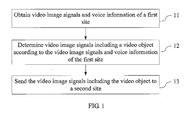
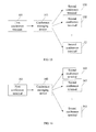
FIG. 1 is a flowchart of a method according to a first embodiment of the present invention; -
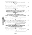
FIG. 2 is a flowchart of a method according to a second embodiment of the present invention; -
FIG 3 is a schematic diagram of an imaging principle of a camera; -
FIG. 4 is a schematic diagram of a first coordinate system used by a site; -
FIG. 5 is a schematic diagram of a second coordinate system used by a site; -
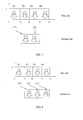
FIG. 6 is a first schematic diagram of the position of a speaker at a first site according to the second embodiment of the present invention; -
FIG 7 is a second schematic diagram of the position of a speaker at the first site according to the second embodiment of the present invention; -
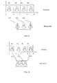
FIG. 8 is a third schematic diagram of the position of a speaker at the first site according to the second embodiment of the present invention; -
FIG. 9 is a fourth schematic diagram of the position of a speaker at the first site according to the second embodiment of the present invention; -
FIG. 10 is a fifth schematic diagram of the position of a speaker at the first site according to the second embodiment of the present invention; -
FIG. 11 is a schematic structural diagram of a conference terminal according to a third embodiment of the present invention; -
FIG. 12 is a schematic diagram of a determining unit in a conference terminal device according to the third embodiment of the present invention; -
FIG. 13 is a schematic structural diagram of a conference managing device according to a fourth embodiment of the present invention; -
FIG. 14 is a schematic diagram of a determining unit in a conference managing device according to the fourth embodiment of the present invention; -
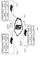
FIG. 15 is a schematic structural diagram of a system according to a fifth embodiment of the present invention; -
FIG. 16 is a schematic structural diagram of a system according to a sixth embodiment of the present invention; and -
FIG. 17 is a schematic diagram of a system instance according to the sixth embodiment of the present invention. - The technical solution of the present invention is hereinafter described in detail with reference to the embodiments and accompanying drawings. Apparently, the described embodiments are only part of rather than all of the embodiments of the present invention. All other embodiments, which can be derived by those of ordinary skill in the art from the embodiments described herein without any creative effort, shall fall within the protection scope of the present invention.
- The embodiments of the present invention provide a method, device, and system for switching video objects in video communication to implement automatic switching of video images displayed at other sites when the speaker changes at a site during a video conference. The method, device, and system for switching video objects in video communication are detailed below with reference to the exemplary embodiments and accompanying drawings.
- During a video conference, the site where the current speaker is located is the first site, and other sites except the first site are the second site.
- As shown in
FIG. 1 , the embodiment of the present invention provides a method for switching video objects in video communication. The method includes the following steps: - 11. Obtain video image signals and voice information of the first site.
- The video image signals and voice information of the site can be collected through a camera device and a microphone array at the site.
- 12. Determine, according to the video image signals and voice information of the first site, video image signals including a video object.
- The participant who is the current speaker at the first site can be determined and regarded as a video object by using an image identification technology and a microphone array technology according to the obtained video image signals and voice information.
- 13. Send the video image signals including the video object to the second site.
- The step of sending the video image signals including the video object to the second site may be sending the video image signals including the video object to the terminal devices of the second site directly, or may be sending the video image signals including the video object to the terminal devices of multiple second sites through a conference managing device such as a multipoint control unit (MCU).
- According to method for switching video objects in video communication provided in this embodiment of the present invention, during the video conference, it can be automatically judged, according to the video image signals and voice information of the first site, which participant is the current speaker, that is, the video object needed to be displayed in the current video images, and then the current video image signals are switched to the video image signals including the video object for displaying to participants of other sites; the method for switching video objects in video communication provided in this embodiment of the present invention implements automatic switching of video image signals during the video conference, thus avoiding switching errors caused by human factors and improving the efficiency of the conference.
- Suppose that four participants P1, P2, P3, and P4 are at the first site, while the video presenting device of the second site can display only two of them.
- As shown in
FIG. 2 , the embodiment of the present invention provides a method for switching video objects in video communication. The method includes the following steps: - 21. Obtain video image signals and voice information of the first site.
- 22. Determine azimuth information of each participant relative to the camera device at the first site according to the video image signals of the first site.
- First, images of all participants in the video images obtained from the camera are identified by using an image identification technology.
- And then, the azimuths of all participants relative to the camera are calculated according to the imaging principle of the camera. The principle is as shown in
FIG. 3 . - In
FIG 3 , origin O corresponds to the center of the camera lens; axis z corresponds to the center line direction of the camera lens; the plane formed by axis x and axis y is vertical to axis z. The plane where point O1 is located is the plane where point P1 is located and which is vertical to axis z. The distance between point O1 and point O along axis z is the object distance, namely, d. The plane where imaging point 02 is located is the plane where imaging point P2 of P1 is located and which is vertical to axis z. The distance between 02 and O along axis z is the image distance, which is equal to the focal length f of the camera (because the object distance is far greater than the image distance, the image distance is regarded as approximately equal to the focal length f of the camera). According to the image identification technology, we can know that the distance between point P2 and axis x2 is |h| and that the distance between point P2 and axis y2 is |w|. Therefore, we can calculate the azimuth of point P1 relative to the camera according to the coordinates (w, h) of imaging point P2 of point P1 in the x2 y2 coordinate system (in this embodiment of the present invention, azimuth information of the participant relative to the camera is represented by azimuth α).
- As shown in
FIG. 4 , the angle of participant P4 relative to the camera is α, which is the azimuth information of the participant relative to the camera. - 23. Determine azimuth information of the current speaker relative to the camera device according to the voice information.
- At the site, a microphone array is set between the video presenting device and the participant. The microphone array may be but not limited to a linear array, a round array, or a cross-shaped array that includes at least two microphones, or may be a microphone array of other forms.
- Because the position of each microphone in the microphone array varies, the distance between the sound from a sound source and each microphone is also different. Therefore, we can detect the delay between audio signals recorded by each microphone, and estimate the azimuth of the current speaker relative to the microphone array according to the delay between audio signals and the position of the microphone in the microphone array.
- The azimuth of the current speaker, namely, the video object needed to be displayed, relative to the camera can be calculated by using the foregoing microphone array technology and according to the position relationship between the microphone array and the camera.
- If the horizontal coordinate system (referred to as a camera coordinate system) used to determine the azimuth of the participant through the video image signals obtained by the camera coincides with the horizontal coordinate system (referred to as a microphone array coordinate system) used to calculate the azimuth of the current speaker through the microphone array, as shown in
FIG. 4 , the center (point O) of the camera lens also coincides with the center (point O') of the microphone array. Therefore, azimuth information (angle β) of the current speaker relative to the microphone array obtained by using the microphone array technology is the azimuth information (angle α) of the current speaker relative to the camera, that is, α = β. - If the camera coordinate system does not coincide with the microphone array coordinate system, the two coordinate systems need to be unified. For example, the camera coordinate system can be unified to the microphone array coordinate system, or the microphone array coordinate system can be unified to the camera coordinate system. As shown in
FIG. 5 , origin O of the camera coordinate system does not coincide with origin O' of the microphone array coordinate system, but the position relationship between origin O and origin O' is known, that is, x1 and y1 are known, and the distance (x2 and y2) between the current speaker and the origin O' can also be obtained by using the microphone array technology. Therefore, we can easily obtain azimuth information α' of the current speaker relative to origin O (the center of the camera lens) according to x1, y1, x2, and y2:
- 24. Find the participant whose azimuth information is consistent with that of the current speaker from participants as a video object.
- Theoretically, azimuth α of the current video object relative to the camera is the same as the azimuth information β (or α') of the current speaker relative to the camera. Therefore, we can compare azimuth information of different participants relative to the camera with azimuth information β (or α') of the current speaker relative to the camera. The participant whose azimuth information relative to the camera is the same as the azimuth information β (or α') of the current speaker is the current video object. In the actual situation, due to the existence of errors, α and β (or α') can hardly be completely equal. In this case, the participant with a smallest absolute difference between the azimuth information relative to the camera and β (or α') is the current video object, where the absolute difference is an absolute value of the difference between two angles.
- If only one speaker or two adjacent speakers are currently present among participants, the second site can display the video image of the speaker normally, and step 26 is performed; if non-adjacent speakers or multiple speakers are currently present among participants, and the second site cannot display video images of the foregoing multiple speakers simultaneously, the video images need to be processed firstly, and step 25 is performed.
- 25. Clip images of the speaker needed to be displayed from the site video image signals, and combine the clipped images into the video image including the speaker needed to be displayed.
- As shown in
FIG. 6 , after image identification, the video image signals of the first site are divided into four parts: P1, P2, P3, and P4. The areas corresponding to the four parts are as shown in Table 1 (where all units are pixels).Table 1 Participant Lower-Left Coordinate of the Area Upper-Right Coordinate of the Area P1 (0,0) (x1-1,y) P2 (x1,0) (x2-1,y) P3 (x2,0) (x3-1,y) P4 (x3,0) (x4-1,y) - If the system detects that participant P1 at the first site is speaking for a long time (as shown in
FIG. 6 ), while the video image of the first site seen by participants at the second site does not include the image of P1, for example, the video image includes P2 and P3, the image needs to be switched to the image including P1. If the video presenting device of the second site can display two persons at each site, a participant adjacent to P1 can be selected for displaying. For example, four participants are present at the first site of this embodiment, and therefore, the image including P1 and P2 can be displayed at the second site. - If two adjacent speakers are present at the first site, the process of determining the range of the video image signals needed to be switched is similar to the process of displaying P1 and P2 images simultaneously, and is not repeatedly described here.
- However, in the following cases, the video image needs to be processed first, and then the range of the video image signals needed to be switched can be determined.
- (1) If multiple speakers are detected (as shown in
FIG 7 ), and the number of speakers is not greater than the number of persons that can be displayed by the video presenting device of the second site, for example, the main speakers at the first site are P1 and P3, the image of P1 and P3 can be clipped from the corresponding video image of the first site, and then recombined and stitched into a new video image signal for displaying by the video presenting device of the second site. - (2) In a collaborative video conference, the following case may occur: only several participants speak, and the number of speakers exceeds the number of persons that can be displayed by the video presenting device of the second site. As shown in
FIG. 8 , P1, P2, and P3 are main speakers. If the video presenting device of the second site can display three persons of the same site, P1, P2, and P3 can be selected for displaying at the second site (as shown inFIG. 8 ); however, the actual case is more similar to the case set in this embodiment of the present invention, that is, only two persons of a site can be displayed simultaneously at the second site; in this case, the areas to be displayed are determined in units of areas. For example, P1, P2, and P3 are all speaking, while only two of them can be displayed at the second site, which requires that an area should be selected from the area including P1 and P2 and the area including P2 and P3 as the video image area for switching; in this case, we can select the area combination with more voice signal energy for displaying by comparing voice signal energy of the two area combinations. - In the case that P1, P2, and P3 are all speaking, another solution is: The center position of the three speakers is calculated according to the site video image signals, and the center position is used as the display center of the video image needed to be switched for the purpose of displaying the video image in the video presenting device of the second site (as shown in
FIG. 9 ). However, this solution will cause the clipping of some images of P1 and P3; in this case, because a blank area exists among P1, P2, and P3, the blank area can be clipped so that images of all speakers can be displayed in the video presenting device of the second site, as shown inFIG. 10 . - 26. Switch the video image signals currently displayed to video image signals including the video object.
- After a participant is judged as a video object, if the video object needed to be displayed does not appear in the video images displayed at the second site, the video image currently displayed needs to be switched to the video image including the video object.
- 27. Send the switched video image signals including the video object to other sites.
- The step of sending the switched video image signals including the video object to other sites may be sending the switched video image signals including the video object to the terminal devices of the second site directly, or sending the switched video image signals including the video object to the terminal devices of multiple second sites through a conference managing device such as an MCU.
- The video presenting device of the second site can display only video images of some participants at the first site; therefore, at the time of sending the video image signals including the video object to the second site, the panoramic video image signals of the first site at a low bit rate are sent together as auxiliary video signals to the second site and displayed. In this way, the participants of the second site can know the situation of the first site more visually, and do not feel an abrupt change during video switching.
- Step numbers provided in this embodiment do not limit the sequence of steps. For example, step 22 and step 23 may occur simultaneously and are performed in real time.
- According to the method for switching video objects in video communication provided in this embodiment of the present invention, it can be automatically judged, according to the extent of matching between azimuth information of each participant relative to the camera and azimuth information of the current speaker relative to the camera, which participant is the current speaker, that is, the video object needed to be displayed in the current video images, and then the currently displayed video image signals are switched to the video image signals including the video object for displaying to participants of other sites; in view of the case that the video presenting device of the second site cannot display all speakers normally when multiple speakers are present at the first site, displaying multiple speakers of a site simultaneously at the second site is implemented by clipping and stitching video images; the method for switching video objects in video communication implements automatic switching of video image signals during the video conference, thus avoiding switching errors caused by human factors and improving the efficiency of the conference.
- To better implement the foregoing method for switching video objects in video communication, this embodiment of the present invention provides a conference terminal used in a video conference; the conference terminal is described in detail below with reference to accompanying drawings.
- As shown in
FIG. 11 , the conference terminal provided in this embodiment of the present invention includes aterminal device 111, and avideo presenting device 112, anaudio outputting device 113, acamera device 114, and amicrophone array 115 that are respectively connected to theterminal device 111, where theterminal device 111 further includes: an obtainingunit 1111, a determiningunit 1112, and a sendingunit 1113. - The obtaining
unit 1111 obtains video image signals and voice information of a site through thecamera device 114 and themicrophone array 115; and then the determiningunit 1112 determines the video image signals including a video object according to the site video image signals and voice information, where the video object is the current speaker of the site; finally, the sendingunit 1113 sends the video image signals including the video object to a second site. - The determining
unit 1112 can determine which participant at the site is the current speaker by using an image identification technology and a microphone array technology according to the obtained site video image signals and voice information, and use the current speaker as the video object. As shown inFIG. 12 , the determiningunit 1112 further includes: a first determiningmodule 11121, a second determiningmodule 11122, a searchingmodule 11123, and aswitching module 11124. - The first determining
module 11121 determines azimuth information of each participant relative to the camera device according to the image identification technology and the imaging principle of the camera and the site video image signals. - The second determining
module 11122 determines azimuth information of the current speaker relative to the camera device according to the microphone array technology and the voice information. - Generally, the azimuth information obtained according to the voice information is azimuth information of the current speaker relative to the microphone array; if the center of the camera lens coincides with the center of the microphone array at the current site, the azimuth information of the current speaker relative to the microphone array is the azimuth information of the current speaker relative to the camera device; if the center of the camera lens does not coincide with the center of the microphone array, the azimuth information of the current speaker relative to the camera device is obtained by converting the azimuth information of the current speaker relative to the microphone array.
- And then the searching
module 11123 finds the participant whose azimuth information is consistent with that of the current speaker from participants as a video object. Consistency with the azimuth information of the current speaker is specifically: being the same as the azimuth information of the current speaker, or having the smallest absolute difference from the azimuth of the current speaker in azimuth information of all participants. - Finally, the
switching module 11124 switches the video image signals currently displayed to video image signals including the video object. - If at least two video objects are present at the first site, and the video presenting device cannot display the at least two video objects simultaneously, the determining
unit 1112 further includes: - a
clipping module 11125, configured to clip image signals corresponding to the video objects needed to be displayed from the site video image signals; and - a combining
module 11126, configured to combine the clipped image signals into video image signals including the video objects needed to be displayed, and send the combined video image signals to theswitching module 11124. - If the number of the second sites is equal to or greater than 2, a conference managing device is required to forward the switched video image signals; in this case, the sending
unit 1113 sends the switched video image signals including video objects to the conference managing device, and then the conference managing device forwards the signals to the second sites. To enable participants at the second sites to see the situation of the first site more visually, the sendingunit 1113 is further configured to send panoramic site video image signals at a low bit rate with the video image signals including video objects to the second sites. - With the conference terminal provided in this embodiment of the present invention, it can be automatically judged, according to the extent of matching between the azimuth of each participant and the azimuth of the current speaker, which participant is the current speaker, that is, the video object needed to be displayed in the current video images, and then the currently displayed video image signals are switched to the video image signals including the video object for displaying to participants of other sites; the conference terminal provided in this embodiment of the present invention implements automatic switching of video image signals during the video conference, thus avoiding switching errors caused by human factors and improving the efficiency of the conference.
- To better implement the foregoing method for switching video objects in video communication, this embodiment of the present invention provides a conference managing device used in a video conference; the conference managing device is described in detail below with reference to accompanying drawings.
- As shown in
FIG. 13 , the conference managing device provided in this embodiment of the present invention includes a receivingunit 131, a determining unit 132, and a sending unit 133. - The receiving
unit 131 receives the video image signals and voice information of a first site, and then the determining unit 132 determines video image signals including a video object according to the site video image signals and voice information, where the video object is the current speaker of the site; finally, the sending unit 133 sends the video image signals including the video object to a second site; here the second site is other sites except the site where the current speaker is located. - The determining unit 132 can determine which participant at the site is the current speaker by using an image identification technology and a microphone array technology according to the obtained site video image signals and voice information, and use the current speaker as the video object. As shown in
FIG. 14 , the determining unit 132 further includes: a first determiningmodule 1321, a second determiningmodule 1322, asearching module 1323, and aswitching module 1324. - The first determining
module 1321 determines azimuth information of each participant relative to the camera device according to the image identification technology and the imaging principle of the camera and the site video image signals. - The second determining
module 1322 determines azimuth information of the current speaker relative to the camera device according to the microphone array technology and the voice information. - Generally, the azimuth information obtained according to the voice information is azimuth information of the current speaker relative to the microphone array; if the center of the camera lens coincides with the center of the microphone array at the current site, the azimuth information of the current speaker relative to the microphone array is the azimuth information of the current speaker relative to the camera device; if the center of the camera lens does not coincide with the center of the microphone array, the azimuth information of the current speaker relative to the camera device is obtained by converting the azimuth information of the current speaker relative to the microphone array.
- And then the
searching module 1323 finds the participant whose azimuth information is consistent with that of the current speaker from participants as a video object. Consistency with the azimuth information of the current speaker is specifically: being the same as the azimuth information of the current speaker, or having the smallest absolute difference from the azimuth of the current speaker in azimuth information of all participants. - Finally, the
switching module 1324 switches the video image signals currently displayed to video image signals including the video object. - If at least two video objects are present at the first site, and the video presenting device cannot display the at least two video objects simultaneously, the determining unit 132 further includes:
- a
clipping module 1325, configured to clip image signals corresponding to the video objects needed to be displayed from the site video image signals; and - a combining
module 1326, configured to combine the clipped image signals into video image signals including the video objects needed to be displayed, and send the combined video image signals to the switching module. - To enable participants at the second sites to see the situation of the first site more visually, the sending unit 133 further sends panoramic site video image signals at a low bit rate with the video image signals including video objects to the second sites.
- With the conference managing device provided in this embodiment of the present invention, it can be automatically judged, according to the extent of matching between the azimuth of each participant and the azimuth of the current speaker, which participant is the current speaker, that is, the video object needed to be displayed in the current video images, and then the currently displayed video image signals are switched to the video image signals including the video object for displaying to participants of other sites; the conference managing device provided in this embodiment of the present invention implements automatic switching of video image signals during the video conference, thus avoiding switching errors caused by human factors and improving the efficiency of the conference.
- An embodiment of the present invention also provides a video conference system that can implement the foregoing method for switching video objects in video communication. As shown in
FIG. 15 , the video conference system includes: afirst conference terminal 151 and at least onesecond conference terminal 152. - The
first conference terminal 151 obtains video image signals and voice information of a first site, determines video image signals including a video object according to the site video image signals and voice information, where the video object is the current speaker of the first site, and sends the video image signals including the video object to the second conference terminal. - The at least one
second conference terminal 152 receives the video image signals including the video object from the first conference terminal and displays the video image signals including the video object. - The first site is the site where the current speaker is located.
- If the number of the second conference terminals is equal to or greater than 2, the video conference system in this embodiment of the present invention further requires a
conference managing device 153, which is configured to obtain the video image signals including the video object from the first conference terminal and send the video image signals to the second conference terminal. - With the video conference system provided in this embodiment of the present invention, the first conference terminal can automatically judge which participant is the current speaker (that is, the video object needed to be displayed in the current video images) during the video conference according to the video image signals and voice information of the first site, and then switch the currently displayed video image signals to the video image signals including the video object and send the video image signals including the video object to the second conference terminal for displaying to participants of the second site; the video conference system provided in this embodiment of the present invention implements automatic switching of video image signals during the video conference, thus avoiding switching errors caused by human factors and improving the efficiency of the conference.
- An embodiment of the present invention also provides a video conference system that can implement the foregoing method for switching video objects in video communication. As shown in
FIG. 16 , the video conference system includes: afirst conference terminal 161, aconference managing device 162, and at least onesecond conference terminal 163. - The
first conference terminal 161 collects video image signals and voice information of a first site and sends the site video image signals and voice information to theconference managing device 162. - The
conference managing device 162 receives the site video image signals and voice information sent by thefirst conference terminal 161, determines video image signals including a video object according to the site video image signals and voice information, where the video object is the current speaker of the first site, and sends the video image signals including the video object to thesecond conference terminal 163. - The at least one
second conference terminal 163 receives the video image signals including the video object from theconference managing device 162 and displays the video image signals including the video object. - The first site is the site where the current speaker is located.
-
FIG. 17 is an embodiment of a specific application of the present invention. The conference managing device is an MCU. - When a video conference is ongoing, the MCU simultaneously receives the site video image signals and voice information provided by conference terminals of sites S1, S2, and S3, and then judges which site is the first site according to the site video image signals and voice information of each site; if S1 is the first site, the MCU determines the video image signals including a video object according to the site video image signals and voice information of S1, and sends the signals to the conference terminals of S2 and S3 for displaying at the second site.
- In the video conference system provided in embodiments of the present invention, the first conference terminal collects video image signals and voice information of the first site and sends them to the conference managing device; and then the conference managing device automatically judges which participant is the current speaker (that is, the video object needed to be displayed in current video images) according to the video image signals and voice information of the first site, and then switches the currently displayed video image signals to the video image signals including the video object and sends the video image signals including the video object to the second conference terminal for displaying to participants of the second site; the video conference system provided in embodiments of the present invention implements automatic switching of video image signals during the video conference, thus avoiding switching errors caused by human factors and improving the efficiency of the conference.
- It is understandable to those of ordinary skill in the art that all or part of the steps of the foregoing embodiments can be implemented by hardware instructed by a program. The program may be stored in a computer readable storage medium. When the program is executed, the steps of the methods in the foregoing embodiments are executed. The storage medium may be any medium that can store program codes, such as a read only memory (ROM), a random access memory (RAM), a magnetic disk and a compact disk-read only memory (CD-ROM).
- Although the invention has been described through some exemplary embodiments, the invention is not limited to such embodiments. It is apparent that those skilled in the art can make various modifications and substitutions to the invention without departing from the spirit and scope of the invention. Therefore, the scope of the present invention is subject to the appended claims.
Claims (14)
- A method for video communication, comprising:obtaining video image signals and voice information of a first site;determining video image signals comprising a video object according to the video image signals and voice information of the first site, wherein the video object is a current speaker of the first site; andsending the video image signals comprising the video object to a second site.
- The method of claim 1, wherein the step of determining the video image signals comprising the video object according to the video image signals and voice information of the first site comprises:determining azimuth information of each participant relative to a camera device according to the video image signals of the first site;determining azimuth information of the current speaker relative to the camera device according to the voice information;finding a participant whose azimuth information is consistent with that of the current speaker from the participants as the video object; andswitching currently displayed video image signals to video image signals comprising the video object.
- The method of claim 2, wherein consistency with the azimuth information of the current speaker comprises:being the same as the azimuth information of the current speaker relative to the camera device; orhaving a smallest absolute difference from an azimuth of the current speaker in azimuth information of all participants.
- The method of claim 2, wherein if at least two video objects exist and a video presenting device cannot display the at least two video objects simultaneously, before switching the currently displayed video image signals to the video image signals comprising the video object, further comprising:clipping image signals corresponding to each video object needed to be displayed from the video image signals of the first site; andcombining the clipped image signals into the video image signals comprising the video object.
- The method of claim 1, wherein the step of sending the video image signals comprising the video object to the second site comprises:sending the video image signals comprising the video object to the second site through a conference managing device; orsending the video image signals comprising the video object to the second site directly.
- A conference terminal, comprising:a terminal device, and a video presenting device, an audio outputting device, a camera device, and a microphone array that are respectively connected to the terminal device, wherein the terminal device comprises:an obtaining unit, configured to obtain video image signals and voice information of a first site;a determining unit, configured to determine video image signals comprising a video object according to the video image signals and voice information of the first site, wherein the video object is a current speaker of the first site; anda sending unit, configured to send the video image signals comprising the video object to a second site.
- The conference terminal of claim 6, wherein the determining unit comprises:a first determining module, configured to determine azimuth information of each participant relative to a camera device according to the video image signals of the first site;a second determining module, configured to determine azimuth information of the current speaker relative to the camera device according to the voice information;a searching device, configured to find a participant whose azimuth information is consistent with that of the current speaker from the participants as the video object; anda switching module, configured to switch currently displayed video image signals to video image signals comprising the video object.
- The conference terminal of claim 7, wherein if at least two video objects exist and the video presenting device cannot display the at least two video objects simultaneously, the determining unit further comprises:a clipping module, configured to clip image signals corresponding to each video object needed to be displayed from the video image signals of the first site; anda combining module, configured to combine the clipped image signals into the video image signals comprising the video object, and send the combined video image signals to the switching module.
- A conference managing device, comprising:a receiving unit, configured to receive video image signals and voice information of a first site;a determining unit, configured to determine video image signals comprising a video object according to the video image signals and voice information of the first site, wherein the video object is a current speaker of the first site; anda sending unit, configured to send the video image signals comprising the video object to a second site.
- The conference managing device of claim 9, wherein the determining unit comprises:a first determining module, configured to determine azimuth information of each participant relative to a camera device according to the video image signals of the first site;a second determining module, configured to determine azimuth information of the current speaker relative to the camera device according to the voice information;a searching device, configured to find a participant whose azimuth information is consistent with that of the current speaker from the participants as the video object; anda switching module, configured to switch currently displayed video image signals to video image signals comprising the video object.
- The conference managing device of claim 10, wherein if at least two video objects exist and a video presenting device cannot display the at least two video objects simultaneously, the determining unit further comprises:a clipping module, configured to clip image signals corresponding to each video object needed to be displayed from the video image signals of the first site; anda combining module, configured to combine the clipped image signals into the video image signals comprising the video object, and send the combined video image signals to the switching module.
- A video conference system, comprising a first conference terminal and at least one second conference terminal, wherein:the first conference terminal is configured to: obtain video image signals and voice information of a first site, determine video image signals comprising a video object according to the video image signals and voice information, and send the video image signals comprising the video object to the second conference terminal;the at least one second conference terminal is configured to receive the video image signals comprising the video object from the first conference terminal and display the video image signals comprising the video object; andthe first site is a site wherein a current speaker is located and the video object is the current speaker of the first site.
- The video conference system of claim 12, further comprising a conference managing device, wherein:the conference managing device is configured to obtain the video image signals comprising the video object from the first conference terminal and send the video image signals comprising the video object to the second conference terminal.
- A video conference system, comprising a first conference terminal, a conference managing device, and at least one second conference terminal, wherein:the first conference terminal is configured to collect video image signals and voice information of a first site and send the video image signals and voice information to the conference managing device;the conference managing device is configured to: receive the video image signals and voice information from the first conference terminal, determine video image signals comprising a video object according to the video image signals and voice information, and send the video image signals comprising the video object to the second conference terminal;the at least one second conference terminal is configured to receive the video image signals comprising the video object from the conference managing device and display the video image signals comprising the video object; andthe first site is a site wherein a current speaker is located and the video object is the current speaker of the first site.
Applications Claiming Priority (2)
| Application Number | Priority Date | Filing Date | Title |
|---|---|---|---|
| CN2008101889262A CN101442654B (en) | 2008-12-26 | 2008-12-26 | Method, apparatus and system for switching video object of video communication |
| PCT/CN2009/073391 WO2010072075A1 (en) | 2008-12-26 | 2009-08-21 | Method, device and system of video communication |
Publications (2)
| Publication Number | Publication Date |
|---|---|
| EP2375741A1 true EP2375741A1 (en) | 2011-10-12 |
| EP2375741A4 EP2375741A4 (en) | 2012-03-14 |
Family
ID=40726874
Family Applications (1)
| Application Number | Title | Priority Date | Filing Date |
|---|---|---|---|
| EP09834028A Ceased EP2375741A4 (en) | 2008-12-26 | 2009-08-21 | Method, device and system of video communication |
Country Status (4)
| Country | Link |
|---|---|
| US (1) | US8730296B2 (en) |
| EP (1) | EP2375741A4 (en) |
| CN (1) | CN101442654B (en) |
| WO (1) | WO2010072075A1 (en) |
Cited By (2)
| Publication number | Priority date | Publication date | Assignee | Title |
|---|---|---|---|---|
| WO2013012576A1 (en) * | 2011-07-20 | 2013-01-24 | Cisco Technology, Inc. | Adaptation of video for use with different number of cameras and displays at endpoints |
| FR3074584A1 (en) * | 2017-12-05 | 2019-06-07 | Orange | PROCESSING DATA OF A VIDEO SEQUENCE FOR A ZOOM ON A SPEAKER DETECTED IN THE SEQUENCE |
Families Citing this family (35)
| Publication number | Priority date | Publication date | Assignee | Title |
|---|---|---|---|---|
| CN101442654B (en) * | 2008-12-26 | 2012-05-23 | 华为终端有限公司 | Method, apparatus and system for switching video object of video communication |
| CN102131071B (en) * | 2010-01-18 | 2013-04-24 | 华为终端有限公司 | Method and device for video screen switching |
| US8395653B2 (en) * | 2010-05-18 | 2013-03-12 | Polycom, Inc. | Videoconferencing endpoint having multiple voice-tracking cameras |
| CN102281424B (en) * | 2010-06-11 | 2013-08-07 | 中兴通讯股份有限公司 | Conference site picture broadcasting method and multipoint control unit |
| CN104038725B (en) * | 2010-09-09 | 2017-12-29 | 华为终端有限公司 | The method and device being adjusted is shown to participant's image in multi-screen video conference |
| CN102404542B (en) * | 2010-09-09 | 2014-06-04 | 华为终端有限公司 | Method and device for adjusting participant's image display in multi-screen video conference |
| CN101951492A (en) * | 2010-09-15 | 2011-01-19 | 中兴通讯股份有限公司 | Method and device for recording videos in video call |
| US8451315B2 (en) | 2010-11-30 | 2013-05-28 | Hewlett-Packard Development Company, L.P. | System and method for distributed meeting capture |
| CN102740042B (en) * | 2011-03-31 | 2015-04-08 | 华为终端有限公司 | Method and device for controlling display position of image of conventioneer in multi-screen video conference |
| CN102186049B (en) * | 2011-04-22 | 2013-03-20 | 华为终端有限公司 | Conference terminal audio signal processing method, conference terminal and video conference system |
| CN103096017B (en) * | 2011-10-31 | 2016-07-06 | 鸿富锦精密工业(深圳)有限公司 | Computer operating power control method and system |
| CN102368816A (en) * | 2011-12-01 | 2012-03-07 | 中科芯集成电路股份有限公司 | Intelligent front end system of video conference |
| CN103986901A (en) * | 2013-02-08 | 2014-08-13 | 中兴通讯股份有限公司 | Method for obtaining needed video streams in video conference and corresponding devices |
| CN104349112B (en) * | 2013-07-31 | 2019-02-01 | 波利康公司 | Video conference device and its method |
| CN105376515B (en) * | 2014-09-02 | 2019-03-19 | 华为技术有限公司 | Method, device and system for presenting communication information for video communication |
| TWI602437B (en) * | 2015-01-12 | 2017-10-11 | 仁寶電腦工業股份有限公司 | Video and audio processing devices and video conference system |
| US9380264B1 (en) | 2015-02-16 | 2016-06-28 | Siva Prasad Vakalapudi | System and method for video communication |
| JP6565777B2 (en) * | 2015-07-10 | 2019-08-28 | 株式会社リコー | COMMUNICATION DEVICE, CONFERENCE SYSTEM, PROGRAM, AND DISPLAY CONTROL METHOD |
| CN105915837B (en) * | 2016-05-30 | 2019-10-25 | 华为技术有限公司 | A video switching method, device and system |
| CN106161946B (en) * | 2016-08-01 | 2019-10-29 | 联想(北京)有限公司 | A kind of information processing method and electronic equipment |
| US10405038B2 (en) * | 2016-08-30 | 2019-09-03 | Patrick Dean Cummins | Systems, methods, and apparatus for network architecture with video hardware basis |
| CN106961568B (en) * | 2017-03-09 | 2021-03-23 | 广州盈可视电子科技有限公司 | A screen switching method, device and system |
| CN107087208B (en) * | 2017-05-25 | 2020-07-07 | 深圳市酷开网络科技有限公司 | Panoramic video playing method, system and storage device |
| CN107682752B (en) * | 2017-10-12 | 2020-07-28 | 广州视源电子科技股份有限公司 | Method, device and system for displaying video picture, terminal equipment and storage medium |
| CN110557554B (en) * | 2018-06-01 | 2023-04-18 | 深圳市冠旭电子股份有限公司 | Image switching device and system |
| CN110636243B (en) * | 2018-06-22 | 2022-03-01 | 中兴通讯股份有限公司 | A conference control method and MCU |
| CN109508404B (en) * | 2018-10-29 | 2020-11-17 | 深圳市轱辘车联数据技术有限公司 | Maintenance teaching video management method and device, terminal equipment and storage medium |
| CN109547732A (en) * | 2018-12-19 | 2019-03-29 | 深圳银澎云计算有限公司 | A kind of audio/video processing method, device, server and video conferencing system |
| US10778941B1 (en) * | 2019-09-27 | 2020-09-15 | Plantronics, Inc. | System and method of dynamic, natural camera transitions in an electronic camera |
| TWI749391B (en) * | 2019-10-30 | 2021-12-11 | 緯創資通股份有限公司 | Video conferencing system and video conferencing method |
| CN113676622A (en) * | 2020-05-15 | 2021-11-19 | 杭州海康威视数字技术股份有限公司 | Video processing method, image pickup apparatus, video conference system, and storage medium |
| CN111785297A (en) * | 2020-07-01 | 2020-10-16 | 广州科天视畅信息科技有限公司 | A kind of voice excitation control method and device |
| CN112084929A (en) * | 2020-09-04 | 2020-12-15 | 苏州科达科技股份有限公司 | Speaker recognition method, device, electronic equipment, storage medium and system |
| CN112887654B (en) * | 2021-01-25 | 2022-05-31 | 联想(北京)有限公司 | Conference equipment, conference system and data processing method |
| CN114594892B (en) * | 2022-01-29 | 2023-11-24 | 深圳壹秘科技有限公司 | Remote interaction method, remote interaction device, and computer storage medium |
Family Cites Families (20)
| Publication number | Priority date | Publication date | Assignee | Title |
|---|---|---|---|---|
| US5689641A (en) * | 1993-10-01 | 1997-11-18 | Vicor, Inc. | Multimedia collaboration system arrangement for routing compressed AV signal through a participant site without decompressing the AV signal |
| US6731334B1 (en) * | 1995-07-31 | 2004-05-04 | Forgent Networks, Inc. | Automatic voice tracking camera system and method of operation |
| US6593956B1 (en) * | 1998-05-15 | 2003-07-15 | Polycom, Inc. | Locating an audio source |
| US20020175990A1 (en) * | 1999-03-31 | 2002-11-28 | Jacquelyn Annette Martino | Mirror based interface for computer vision applications |
| GB9908545D0 (en) * | 1999-04-14 | 1999-06-09 | Canon Kk | Image processing apparatus |
| US6795106B1 (en) * | 1999-05-18 | 2004-09-21 | Intel Corporation | Method and apparatus for controlling a video camera in a video conferencing system |
| US6766035B1 (en) * | 2000-05-03 | 2004-07-20 | Koninklijke Philips Electronics N.V. | Method and apparatus for adaptive position determination video conferencing and other applications |
| JP2001339703A (en) * | 2000-05-26 | 2001-12-07 | Nec Corp | Video conference system and camera control device and camera control method in video conference system |
| US20020140804A1 (en) * | 2001-03-30 | 2002-10-03 | Koninklijke Philips Electronics N.V. | Method and apparatus for audio/image speaker detection and locator |
| US6611281B2 (en) | 2001-11-13 | 2003-08-26 | Koninklijke Philips Electronics N.V. | System and method for providing an awareness of remote people in the room during a videoconference |
| US8144854B2 (en) * | 2001-12-31 | 2012-03-27 | Polycom Inc. | Conference bridge which detects control information embedded in audio information to prioritize operations |
| US7404001B2 (en) * | 2002-03-27 | 2008-07-22 | Ericsson Ab | Videophone and method for a video call |
| US7852369B2 (en) | 2002-06-27 | 2010-12-14 | Microsoft Corp. | Integrated design for omni-directional camera and microphone array |
| NO318096B1 (en) * | 2003-05-08 | 2005-01-31 | Tandberg Telecom As | Audio source location and method |
| JP4809624B2 (en) | 2005-04-21 | 2011-11-09 | 彌吉郎 酒井 | Video conference system |
| EP1739966A1 (en) * | 2005-06-30 | 2007-01-03 | Pixartis SA | System for videoconferencing |
| JP4356663B2 (en) * | 2005-08-17 | 2009-11-04 | ソニー株式会社 | Camera control device and electronic conference system |
| NO327899B1 (en) * | 2007-07-13 | 2009-10-19 | Tandberg Telecom As | Procedure and system for automatic camera control |
| US9060094B2 (en) * | 2007-09-30 | 2015-06-16 | Optical Fusion, Inc. | Individual adjustment of audio and video properties in network conferencing |
| CN101442654B (en) * | 2008-12-26 | 2012-05-23 | 华为终端有限公司 | Method, apparatus and system for switching video object of video communication |
-
2008
- 2008-12-26 CN CN2008101889262A patent/CN101442654B/en active Active
-
2009
- 2009-08-21 WO PCT/CN2009/073391 patent/WO2010072075A1/en not_active Ceased
- 2009-08-21 EP EP09834028A patent/EP2375741A4/en not_active Ceased
-
2011
- 2011-06-24 US US13/167,873 patent/US8730296B2/en active Active
Cited By (4)
| Publication number | Priority date | Publication date | Assignee | Title |
|---|---|---|---|---|
| WO2013012576A1 (en) * | 2011-07-20 | 2013-01-24 | Cisco Technology, Inc. | Adaptation of video for use with different number of cameras and displays at endpoints |
| FR3074584A1 (en) * | 2017-12-05 | 2019-06-07 | Orange | PROCESSING DATA OF A VIDEO SEQUENCE FOR A ZOOM ON A SPEAKER DETECTED IN THE SEQUENCE |
| WO2019110913A1 (en) * | 2017-12-05 | 2019-06-13 | Orange | Processing of data of a video sequence in order to zoom on a speaker detected in the sequence |
| US11076224B2 (en) | 2017-12-05 | 2021-07-27 | Orange | Processing of data of a video sequence in order to zoom to a speaker detected in the sequence |
Also Published As
| Publication number | Publication date |
|---|---|
| EP2375741A4 (en) | 2012-03-14 |
| CN101442654A (en) | 2009-05-27 |
| CN101442654B (en) | 2012-05-23 |
| US8730296B2 (en) | 2014-05-20 |
| WO2010072075A1 (en) | 2010-07-01 |
| US20110249085A1 (en) | 2011-10-13 |
Similar Documents
| Publication | Publication Date | Title |
|---|---|---|
| US8730296B2 (en) | Method, device, and system for video communication | |
| US10264210B2 (en) | Video processing apparatus, method, and system | |
| AU2013236158B2 (en) | Teleconference system and teleconference terminal | |
| US10440322B2 (en) | Automated configuration of behavior of a telepresence system based on spatial detection of telepresence components | |
| EP2323425B1 (en) | Method and device for generating audio signals | |
| JP5857674B2 (en) | Image processing apparatus and image processing system | |
| CN113676693B (en) | Screen presentation method, video conferencing system and readable storage medium | |
| US9641585B2 (en) | Automated video editing based on activity in video conference | |
| US7576766B2 (en) | Normalized images for cameras | |
| US20110050842A1 (en) | Distance learning via instructor immersion into remote classroom | |
| KR101497168B1 (en) | Techniques for detecting a display device | |
| EP3546976B1 (en) | Device control method, apparatus and system | |
| JP5929221B2 (en) | Scene state switching system and method based on dynamic detection of region of interest | |
| US10951859B2 (en) | Videoconferencing device and method | |
| EP2993860B1 (en) | Method, apparatus, and system for presenting communication information in video communication | |
| JP2017034502A (en) | COMMUNICATION DEVICE, COMMUNICATION METHOD, PROGRAM, AND COMMUNICATION SYSTEM | |
| EP4106326A1 (en) | Multi-camera automatic framing | |
| WO2018209879A1 (en) | Method and device for automatically selecting camera image, and audio and video system | |
| CN104349111A (en) | Meeting place creating method and system of video conference | |
| US20210367985A1 (en) | Immersive telepresence video conference system | |
| CN108563410B (en) | Display control method and electronic equipment | |
| JP2009049734A (en) | Microphone with camera, control program for microphone with camera, and video conference system | |
| JP2007212664A (en) | Liquid crystal display device | |
| CN213213667U (en) | Interactive conference device based on visual and sound fusion | |
| JP2009027246A (en) | Television conference apparatus |
Legal Events
| Date | Code | Title | Description |
|---|---|---|---|
| PUAI | Public reference made under article 153(3) epc to a published international application that has entered the european phase |
Free format text: ORIGINAL CODE: 0009012 |
|
| 17P | Request for examination filed |
Effective date: 20110704 |
|
| AK | Designated contracting states |
Kind code of ref document: A1 Designated state(s): AT BE BG CH CY CZ DE DK EE ES FI FR GB GR HR HU IE IS IT LI LT LU LV MC MK MT NL NO PL PT RO SE SI SK SM TR |
|
| A4 | Supplementary search report drawn up and despatched |
Effective date: 20120213 |
|
| RIC1 | Information provided on ipc code assigned before grant |
Ipc: H04N 7/14 20060101ALI20120207BHEP Ipc: H04N 7/15 20060101AFI20120207BHEP |
|
| DAX | Request for extension of the european patent (deleted) | ||
| 17Q | First examination report despatched |
Effective date: 20120625 |
|
| 17Q | First examination report despatched |
Effective date: 20120806 |
|
| REG | Reference to a national code |
Ref country code: DE Ref legal event code: R003 |
|
| STAA | Information on the status of an ep patent application or granted ep patent |
Free format text: STATUS: THE APPLICATION HAS BEEN REFUSED |
|
| 18R | Application refused |
Effective date: 20150320 |