EP2375646B1 - A system and method for ethernet protection switching in a provider backbone bridging traffic engineering domain - Google Patents
A system and method for ethernet protection switching in a provider backbone bridging traffic engineering domain Download PDFInfo
- Publication number
- EP2375646B1 EP2375646B1 EP11161105A EP11161105A EP2375646B1 EP 2375646 B1 EP2375646 B1 EP 2375646B1 EP 11161105 A EP11161105 A EP 11161105A EP 11161105 A EP11161105 A EP 11161105A EP 2375646 B1 EP2375646 B1 EP 2375646B1
- Authority
- EP
- European Patent Office
- Prior art keywords
- pbb
- trunk
- component
- esp
- vid
- Prior art date
- Legal status (The legal status is an assumption and is not a legal conclusion. Google has not performed a legal analysis and makes no representation as to the accuracy of the status listed.)
- Active
Links
- 238000000034 method Methods 0.000 title claims abstract description 33
- 239000012717 electrostatic precipitator Substances 0.000 claims abstract 3
- 238000012544 monitoring process Methods 0.000 claims description 19
- 238000013507 mapping Methods 0.000 claims description 11
- 230000007547 defect Effects 0.000 claims description 10
- 238000012423 maintenance Methods 0.000 claims description 8
- 201000000760 cerebral cavernous malformation Diseases 0.000 claims 6
- 230000008878 coupling Effects 0.000 claims 2
- 238000010168 coupling process Methods 0.000 claims 2
- 238000005859 coupling reaction Methods 0.000 claims 2
- 238000010586 diagram Methods 0.000 description 10
- 230000002457 bidirectional effect Effects 0.000 description 8
- 238000005516 engineering process Methods 0.000 description 7
- 230000007246 mechanism Effects 0.000 description 5
- 230000009471 action Effects 0.000 description 4
- 230000008859 change Effects 0.000 description 4
- 230000005540 biological transmission Effects 0.000 description 3
- 238000004891 communication Methods 0.000 description 3
- 230000008569 process Effects 0.000 description 3
- 230000001360 synchronised effect Effects 0.000 description 3
- 230000008901 benefit Effects 0.000 description 2
- 238000001914 filtration Methods 0.000 description 2
- 230000011664 signaling Effects 0.000 description 2
- 230000002776 aggregation Effects 0.000 description 1
- 238000004220 aggregation Methods 0.000 description 1
- 239000000969 carrier Substances 0.000 description 1
- 230000007812 deficiency Effects 0.000 description 1
- 230000006855 networking Effects 0.000 description 1
- 230000003287 optical effect Effects 0.000 description 1
- 230000000737 periodic effect Effects 0.000 description 1
- 238000011084 recovery Methods 0.000 description 1
- 238000000926 separation method Methods 0.000 description 1
- 230000001052 transient effect Effects 0.000 description 1
- 230000001960 triggered effect Effects 0.000 description 1
Images


Classifications
-
- H—ELECTRICITY
- H04—ELECTRIC COMMUNICATION TECHNIQUE
- H04L—TRANSMISSION OF DIGITAL INFORMATION, e.g. TELEGRAPHIC COMMUNICATION
- H04L41/00—Arrangements for maintenance, administration or management of data switching networks, e.g. of packet switching networks
- H04L41/06—Management of faults, events, alarms or notifications
- H04L41/0654—Management of faults, events, alarms or notifications using network fault recovery
-
- H—ELECTRICITY
- H04—ELECTRIC COMMUNICATION TECHNIQUE
- H04L—TRANSMISSION OF DIGITAL INFORMATION, e.g. TELEGRAPHIC COMMUNICATION
- H04L41/00—Arrangements for maintenance, administration or management of data switching networks, e.g. of packet switching networks
- H04L41/06—Management of faults, events, alarms or notifications
-
- H—ELECTRICITY
- H04—ELECTRIC COMMUNICATION TECHNIQUE
- H04L—TRANSMISSION OF DIGITAL INFORMATION, e.g. TELEGRAPHIC COMMUNICATION
- H04L43/00—Arrangements for monitoring or testing data switching networks
- H04L43/06—Generation of reports
- H04L43/065—Generation of reports related to network devices
-
- H—ELECTRICITY
- H04—ELECTRIC COMMUNICATION TECHNIQUE
- H04L—TRANSMISSION OF DIGITAL INFORMATION, e.g. TELEGRAPHIC COMMUNICATION
- H04L43/00—Arrangements for monitoring or testing data switching networks
- H04L43/08—Monitoring or testing based on specific metrics, e.g. QoS, energy consumption or environmental parameters
- H04L43/0805—Monitoring or testing based on specific metrics, e.g. QoS, energy consumption or environmental parameters by checking availability
- H04L43/0811—Monitoring or testing based on specific metrics, e.g. QoS, energy consumption or environmental parameters by checking availability by checking connectivity
Definitions
- Ethernet has become the undisputed leading Local Area Network (LAN) technology due to the intrinsic characteristics of the technology, such as being simple to implement and use, cheap to employ, easy to manage, and backward compatible.
- LAN Local Area Network
- Ethernet technology requires specific enhancements if it is to fulfill these carrier-grade requirements.
- IEEE Institute of Electrical and Electronics Engineers
- PBB-TE Provider Backbone Bridge Traffic Engineering
- PBB-TE One of the key points addressed in PBB-TE is how to provide end-to-end linear protection for PBB-TE trunks, where a dedicated protection PBB-TE trunk is established for a particular trunk, and the traffic is automatically switched from the working (primary) PBB-TE trunk to the protection (backup) PBB-TE trunk when a failure occurs on the primary trunk.
- ITU-T International Telecommunication Union-Telecommunication
- bridge for the switch that selects either or both of the transmit paths at the sending end of a protection domain. It should be understood that this is not the same definition as the term "bridge” utilized in the IEEE 802 standard.
- the ITU-T linear protection bridge refers to a "protection bridge”.
- bidirectional linear protection schemes operate synchronously in the sense that a traffic selection action at one end also triggers a corresponding selection action at the other end on traffic in the reverse direction.
- traffic in both directions share the same path (i.e., either working or protection).
- Linear protection schemes are usually configurable to be “revertive” or “non-revertive”, where reception and transmission traffic, where applicable reverts, to the working path automatically once OAM indicates the fault or defect has cleared.
- Hold-off times ensure the fault is not just a transient event, arising from some lower level protection switching for instance, while restore times ensures the performance of the working path is fully restored before switching back to it. Obviously, the overall recovery time is greater.
- ITU-T through the G.8031/Y.1342 Recommendation, defines the use of the APS function and protocol for point-to-point VLAN-based subnetwork connection in Ethernet transport networks.
- the APS protocol is used to coordinate the two ends of a protection domain. APS messages are only sent on the protection path.
- Direct application of the G.8031 mechanisms on in a PBB-TE domain introduces additional complexity as the advent of the APS Protocol Data Unit (PDU) for signaling purposes contains substantial redundant information leading to a non-cost efficient solution.
- PDU Protocol Data Unit
- the G.8031 Recommendation states it is desirable for Continuity Check Messages (CCMs) to be sent with an interval of 3.3ms and for the first three APS messages (resulting from a protection switch event at the originating end) to also be sent with a similar interval of 3.3ms and then again with an interval of 5 seconds. This permits the loss of up to two APS messages due to errors or other phenomena while still achieving a 50ms protection switch time.
- CCMs Continuity Check Messages
- U.S. Patent Application Publication No. 2004/156313 to Hofmeister, et al. discloses a method for providing protection switching in a backbone network such that working and protection trunks are established. The working trunk is monitored by a central control unit and a switching to the protection trunk is performed when a failure is detected by the control unit.
- Hofmeister mentions Ethernet and VLANs which are connected to the backbone network, but does not disclose Ethernet protection switching, since the backbone network is not operating according to Ethernet technology, but is only connected to an Ethernet network.
- U.S. Patent No. 7,093,027 to Shabtay et al. discloses a method for establishing two physical Ethernet links between node pairs of a network such that one link is used for each communication direction between the respective node pairs.
- a VLAN may be established in the network, but the physical Ethernet connection with the two Ethernet links between each node pair remains hidden in the VLAN.
- Shabtay does not describe a backbone network with Ethernet protection switching between trunks.
- the present invention provides a 1:1 bidirectional linear protection switching capability in a PBB-TE domain leveraging on the existing IEEE 802.1Qag Connectivity Fault Management (CFM), CCMs, and RDI field.
- CCM Connectivity Fault Management
- RDI RDI field.
- the present invention also provides a simplified and efficient solution, which is well aligned to employ Ethernet technology.
- the present invention is directed to a method of providing Ethernet protection switching in a PBB-TE Domain.
- the method begins by establishing two PBB-TE trunks between a first B-component and a second B-component. Each trunk includes two unidirectional Ethernet Switching Paths (ESPs), each associated with a possibly different VLAN Identifier (VID).
- the method includes mapping data traffic onto the first PBB-TE trunk, where the first PBB-TE trunk corresponds to a working entity and the second PBB-TE trunk corresponding to a backup protection entity. Data traffic is sent on the first trunk via an ESP associated with one VID in one direction and another ESP associated with a possibly different VID in the opposite direction.
- the PBB-TE trunks are monitored for faults. Upon detecting a fault on one PBB-TE trunk, data traffic is remapped onto the other PBB-TE trunk via a third ESP associated with a third VID and a fourth ESP associated with a fourth VID.
- the present invention is directed to a system for providing Ethernet protection switching in a PBB-TE Domain.
- the system includes a first PBB-TE trunk between a first B-component and a second B-component, the first PBB-TE trunk having a first ESP for unidirectional traffic from the first B-component to the second B-component and a second ESP for unidirectional traffic from the second B-component to the first B-component.
- the first ESP is associated with a first VID and the second ESP is associated with a second VID.
- the system also includes a second PBB-TE trunk between the first B-component and the second B-component.
- the present invention is directed to a node for providing Ethernet protection switching in a PBB-TE Domain.
- the node connects to a first PBB-TE trunk between the node and a second node.
- the first PBB-TE trunk has a first ESP for unidirectional traffic from the node to the second node and a second ESP for unidirectional traffic from the second node to the node.
- the first ESP is associated with a first VID and the second ESP is associated with a second VID.
- the node also connects to a second PBB-TE trunk between the node and the second node.
- the second PBB-TE trunk has a third ESP for unidirectional traffic from the node to the second node and a fourth ESP for unidirectional traffic from the second node to the node.
- the third ESP is associated with a third VID and the fourth ESP is associated with a fourth VID.
- the node maps data traffic onto the first PBB-TE trunk.
- the first PBB-TE trunk corresponds to a working entity and the second PBB-TE trunk corresponds to a backup protection entity.
- the two PBB-TE trunks are monitored for faults. Upon detecting a fault on one PBB-TE trunk, the node remaps data traffic onto the other PBB-TE trunk.
- the present invention is a system and method for Ethernet protection switching in a PBB-TE domain.
- the present invention provides a 1:1 bidirectional linear protection switching capabilities in a PBB-TE domain.
- BEBs Backbone Edge Bridges
- PBBN Provider Backbone Bridged Network
- BEBs are assumed to be B-BEBs or IB-BEBs each containing a B-Component.
- the protection domain is defined to be the area between the Customer Backbone Ports (CBPs) on the different B-Components of the involved BEBs.
- CBPs Customer Backbone Ports
- ESPs are provisioned from one BEB to the other, each one identified by the tuple ⁇ B-DA, B-SA, B-VID>.
- Each ESP represents a unidirectional path and the ESP pairs that form the bidirectional path define a PBB-TE trunk.
- the ESPs belonging to the same PBB-TE trunk are co-routed, but may also be identified by different B-VIDs.
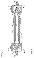
- FIG. 2 is a simplified block diagram of a network 100 illustrating PBB-TE trunk setup in the preferred embodiment of the present invention.
- the network 100 includes at least two PBB-TE trunks, PBB-TE (Working Entity) trunk 102 and PBB-TE (Protection Entity) trunk 104, between a BEB 106 having West B-Component 108 and a BEB 110 having an East B-Component 112.
- the PBB-TE trunk 102 includes a West to East ESP 114 and an East to West ESP 116. Each ESP may correspond to the same or different B-VID settings for the two different directions.
- the PBB-TE trunk 104 includes a West to East ESP 118 and an East to West ESP 120.
- the ESPs 114, 116, 118, and 120 are set by configuring entries in the filtering databases (FDBs) on all the bridges that these ESPs need to pass through and the VLAN membership of each participating port has to be set.
- FDBs filtering databases
- the West B-Component 108 includes a Customer Backbone Port (CBP) 126 and a number of Provider Network Ports (PNPs), PNP 122, and PNP 124.
- the East B-Component 112 includes a CBP 164, and a number of PNPs, PNP 160 and PNP 162.
- the ESP 114 associated with VID 128 is part of the Working Entity 102 and is configured between CBP 126 and CBP 164.
- another ESP 118, associated with VID 130 which is part of the Protection Entity 104 and is configured between the CBP 126 and the CBP 164. Since ESP 114 is associated with VID 128, ports CBP 126 and PNP 122 on the West B-component 108 and ports PNP 160 and CPB 164 on the East B-Component 112 are configured to be members of the VID 128 member set.
- ports CBP 126 and PNP 124 on the West B-component 108 and ports PNP 162 and CPB 164 on the East B-Component 112 are configured to be members of the VID 130 member set.
- the ESP 116 associated with VID 166 which is part of the Working Entity 102 and is configured between CBP 164 and CBP 126
- a fourth ESP 120, associated with VID 168 which is part of the Protection Entity 104 and is configured between the CBP 164 and the CBP 126.
- ports CBP 126 and PNP 122 on the West B-component 108 and ports PNP 160 and CPB 164 on the East B-Component 112 are configured to be members of the VID 166 member set.
- ESP 120 is associated with VID 168, ports CBP 126 and PNP 124 on the West B-component 108 and ports PNP 162 and CPB 164 on the East B-Component 112 are configured to be members of the VID 168 member set.
- Frames are tagged for a specific VID and may only egress or ingress with associated ports.
- Configuring the PBB-TE trunks means that the corresponding Maintenance Associations (MAs) are configured as well.
- MAs Maintenance Associations
- One MA is set to monitor the top (trunk-1) PBB-TE trunk and a second to monitor the bottom (trunk-2) PBB-TE.
- Each of these two MAs may be associated with a pair of Virtual LAN Identifiers (VIDs), where each VID corresponds to one unidirectional ESP.
- VIDs Virtual LAN Identifiers
- the MA that monitors the PBB-TE trunk-1 may then contain both the VIDs in its VID list.
- the Maintenance End Points (MEPs), associated with this MA are Up MEPs, configured on the CBPs that demark the associated PBB-TE trunk.
- each of the MEPs has its own primary VID (e.g., VID 128 for the MEP on the West B-component associated with the PBB-TE trunk 102, and VID 166 for the MEP on the East B-component).
- VID 128 for the MEP on the West B-component associated with the PBB-TE trunk 102
- VID 166 for the MEP on the East B-component
- each MEP may receive frames that are tagged with any of the VIDs in the MA list, but send frames that are tagged only with that MEP's primary VID.
- the MEP for the working entity on the West B-component may send only specified VID 128 tagged Continuity Check Messages (CCMs) while the corresponding MEP on the East component may only send VID 166 tagged frames.
- CCMs Continuity Check Messages
- Both MEPs may receive CCM frames that are tagged for either VID 166 or 128.
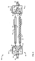
- FIG. 3 is a simplified block diagram illustrating mapping of specific data traffic to a working entity in the network 100 of FIG. 2 .
- the CBP's PVID value for the CBP 126 is associated with VID 128, while the CBP 164 is associated with the VID 166.
- the network includes an MEP 200 associated with VID 128 on the West B-Component 108 and a MEP 202 associated with the VID 166 on the East B-Component 112.
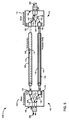
- FIG. 4 is a simplified block diagram illustrating a fault in a working entity of the network 100 of FIG. 2 . If a fault occurs at any of the ESPs, the MEP on the receiving end is notified. For example, if a fault 300 on the ESP 114 occurs, the MEP 202 on the East B-component 112 declares a remote MEP defect by setting an rMEPCCMdefect parameter.
- the timer counter for timing out CCMs has a granularity finer than or equal to 1/4 of the time represented by the CCMinterval variable (the configured time between CCM transmissions).
- a Bridge does not set rMEPCCMdefect within (3.25 * CCMinterval seconds of the receipt of a CCM, and sets rMEPCCMdefect within (3.5*CCMinterval) seconds after the receipt of the last CCM.
- the setting of the rMEPCCMdefect parameter results in a change of the PVID parameter of the CBP to VID 168, which is the BVID of the associated provisioned ESP on the protection PBB-TE trunk 104 (the PVID parameter also changes when the xConCCMdefect or the errorCCMdefect parameters are set as these indicate a very serious misconfiguration problem). All subsequent CCMs sent via the MEP associated with the VID 166 have their RDI field set (for as long as proper CCMs are not received by the MEP).
- FIG. 5 is a simplified block diagram of the network 100 illustrating remapping of specific data traffic to the protection entity.
- Reception of a CCM frame with the RDI field set causes the associated B-VID entry in the Backbone Service Instance table to change to the preconfigured value of the protection ESP (i.e., associating with the ESP 118 and corresponding VID 130).
- the PVID parameter of the CBP 126 on the West B-component 108 is changed to the preconfigured value of the protection ESP. This results in moving the specific service instance to the protection PBB-TE trunk 104 as depicted in FIG. 5 .
- FIG. 6 is a flow chart illustrating the steps of setting up and mapping PBB-TE trunks to provide protection switching capabilities in a PBB-TE domain.
- the PBB-TE trunks are set up.
- the PBB-TE trunk 102 is established as the working entity and includes the ESP 114 associated with the VID 128 in one direction (i.e., west to east) and the ESP 116 associated with the VID 166 in another direction (i.e., east to west).
- the PBB-TE trunk 104 is established as the protection entity and includes the ESP 118 associated with the VID 130 in one direction (i.e., west to east) and the ESP 120 associated with the VID168 in another direction (i.e., east to west).
- data traffic is mapped to the specified PBB-TE trunk (i.e., PBB-TE trunk 102) by configuring the CBP parameters.
- the CBP backbone instance service identifier is used to allow only specific service instances to be carried by the PBB-TE trunk while the CBP's B-VID column in their Backbone Service Instance tables.
- the Port VID (PVID) parameter may be used to map the identified service instances to a specific ESP.
- the CBP's PVID or B-VID value for the CBP 126 is associated with the VID 128 while the CBP 164 is associated with the VID 166.
- frames of specific I-SID values that reach the CBP on the West B-component 108 are mapped to the ESP 114, while specific frames that reach the CBP on the East B-component 112 are mapped on the ESP 116.
- the PBB-TE trunk 102 corresponds to the working entity
- PBB-TE trunk 104 corresponds to a stand-by protection entity.
- CCM frames are exchanged on both the working and protected entities in order to regularly check the provided connectivity.
- step 404 the trunks are monitored for faults.
- step 406 it is determined if a fault is detected. If a fault is not detected, the method continues to monitor the trunks in step 404. However, in step 406, if it is determined that a fault on the working entity is detected, the method moves to step 408 where data traffic is remapped to the protection entity. If a fault occurs at any of the ESPs, the MEP on the receiving end is notified. For example, if a fault 300 on the ESP 114 occurs, the MEP 202 on the East B-component 112 declares a remote MEP defect by setting an rMEPCCMdefect parameter.
- the timer counter for timing out CCMs has a granularity finer than or equal to 1/4 of the time represented by the CCMinterval variable (the configured time between CCM transmissions).
- a Bridge does not set rMEPCCMdefect within (3.25 * CCMinterval seconds of the receipt of a CCM, and sets rMEPCCMdefect within (3.5*CCMinterval) seconds after the receipt of the last CCM.
- the setting of the rMEPCCMdefect parameter results in a change of the Backbone Service Instance table's B-VID column or the PVID parameter of the CBP to the VID 168, which is the BVID of the associated provisioned ESP on the protection PBB-TE trunk 104.
- All subsequent CCMs sent via the MEP associated with the VID 166 have a RDI field set (for as long as proper CCMs are not received by the MEP).
- a reception of a CCM frame with the RDI field set (or an event that causes setting of the someRMEPCCMdefect, xConCCMdefect or errorCCMdefect) causes a change of the Backbone Service Instance table's B-VID column value or the PVID parameter of the CBP 126 on the West B-component 108, to the preconfigured value of the protection ESP (i.e., associating with the ESP 118 and corresponding VID 130). This results in moving the specific service instance to the protection PBB-TE trunk 104.
- the present invention provides a system and method offering a 1:1 bidirectional linear protection switching capability in a PBB-TE domain leveraging on the existing IEEE 802.1Qag Connectivity Fault Management (CFM), CCMs, and RDI field.
- CCM Connectivity Fault Management
- the present invention also provides a simplified and efficient solution, which is well aligned with the intrinsic characteristics of Ethernet technology.
- Embodiments of the invention include a system for providing Ethernet protection switching in a Provider Backbone Bridging Traffic Engineering, PBB-TE, Domain.
- the system includes a first PBB-TE trunk between a first B-component and a second B-component, the first PBB-TE trunk having a first ESP for unidirectional traffic from the first B-component to the second B-component and a second ESP for unidirectional traffic from the second B-component to the first B-component.
- the first ESP is associated with a first VID and the second ESP is associated with a second VID.
- the system also includes a second PBB-TE trunk between the first B-component and the second B-component.
- the second PBB-TE has a third ESP for unidirectional traffic from the first B-component to the second B-component and a fourth ESP for unidirectional traffic from the second B-component to the first B-component.
- the third ESP is associated with a third VID and the fourth ESP is associated with a fourth VID.
- the system maps data traffic onto the first PBB-TE trunk where the first PBB-TE trunk corresponds to a working entity and the second PBB-TE trunk corresponds to a backup protection entity.
- the two PBB-TE trunks are monitored for faults. Upon detecting a fault on one PBB-TE trunk, data traffic is remapped onto the other PBB-TE trunk.
- the monitoring means may also includes means for monitoring the second trunk for faults, wherein when a fault is detected on the second trunk, the remapping means remaps data traffic onto the first trunk.
- the first B-component may include a first ingress port associated with the second VID and a first egress port associated with the first VID, the first ingress port receiving data traffic via the second ESP and the first egress port send data traffic via the first ESP to the second B-component.
- the second B-component may include a second ingress port associated with the first VID and a second egress port associated with the second VID, the second ingress port receiving data traffic via the first ESP and the second egress port sending data traffic via the second ESP to the first B-component.
- the data traffic may be remapped onto the second trunk by reconfiguring the ports in the first and second B-components to send and receive traffic via the third and fourth ESPs.
- the system may further comprise a first Maintenance Association, MA, to monitor the first trunk and a second MA to monitor the second trunk.
- the first MA may be associated with the first and second VIDs and the second MA is associated with the third and fourth VIDs.
- the first B-component may include a first Maintenance End Point (MEP), for monitoring the first ESP, the first MEP being associated with the first VID.
- the second B-component may further include a second MEP for monitoring the second ESP, the second MEP being associated with the second VID.
- the first MEP may further send Continuity Check Messages, CCMs, to the second B-component via the first ESP and the second MEP send CCMs via the second ESP.
- the first B-component may include a third MEP for monitoring the third ESP, the third MEP being associated with the third VID.
- the second B-component may further include a fourth MEP for monitoring the fourth ESP, the fourth MEP being associated with the fourth VID.
- the third MEP may further send CCMs to the third B-component via the third ESP and the fourth MEP send CCMs via the fourth ESP.
- the first or second MEP may detect the fault and set a defect setting parameter, thereby triggering the remapping data traffic onto the second trunk.
- the system may further comprise means for sending Continuity Check Messages, CCMs, via the first and second trunks to check connectivity of the trunks.
- CCMs Continuity Check Messages
Landscapes
- Engineering & Computer Science (AREA)
- Computer Networks & Wireless Communication (AREA)
- Signal Processing (AREA)
- Environmental & Geological Engineering (AREA)
- Data Exchanges In Wide-Area Networks (AREA)
- Emergency Protection Circuit Devices (AREA)
- Train Traffic Observation, Control, And Security (AREA)
- Mobile Radio Communication Systems (AREA)
Priority Applications (1)
| Application Number | Priority Date | Filing Date | Title |
|---|---|---|---|
| PL11161105T PL2375646T3 (pl) | 2007-11-02 | 2008-10-31 | System i sposób przełączania zabezpieczenia Ethernet w domenie inżynierii ruchu mostkowanych sieci szkieletowych dostawcy |
Applications Claiming Priority (3)
| Application Number | Priority Date | Filing Date | Title |
|---|---|---|---|
| US98489207P | 2007-11-02 | 2007-11-02 | |
| EP08832775A EP2232783B1 (en) | 2007-11-02 | 2008-10-31 | Method for ethernet protection switching |
| PCT/IB2008/002936 WO2009056972A1 (en) | 2007-11-02 | 2008-10-31 | A system and method for ethernet protection switching in a provider backbone bridging traffic engineering domain |
Related Parent Applications (2)
| Application Number | Title | Priority Date | Filing Date |
|---|---|---|---|
| EP08832775A Division EP2232783B1 (en) | 2007-11-02 | 2008-10-31 | Method for ethernet protection switching |
| EP08832775.4 Division | 2008-10-31 |
Publications (2)
| Publication Number | Publication Date |
|---|---|
| EP2375646A1 EP2375646A1 (en) | 2011-10-12 |
| EP2375646B1 true EP2375646B1 (en) | 2012-10-03 |
Family
ID=40491098
Family Applications (2)
| Application Number | Title | Priority Date | Filing Date |
|---|---|---|---|
| EP08832775A Active EP2232783B1 (en) | 2007-11-02 | 2008-10-31 | Method for ethernet protection switching |
| EP11161105A Active EP2375646B1 (en) | 2007-11-02 | 2008-10-31 | A system and method for ethernet protection switching in a provider backbone bridging traffic engineering domain |
Family Applications Before (1)
| Application Number | Title | Priority Date | Filing Date |
|---|---|---|---|
| EP08832775A Active EP2232783B1 (en) | 2007-11-02 | 2008-10-31 | Method for ethernet protection switching |
Country Status (12)
| Country | Link |
|---|---|
| US (3) | US8144576B2 (da) |
| EP (2) | EP2232783B1 (da) |
| CN (2) | CN101843049B (da) |
| AT (1) | ATE505877T1 (da) |
| BR (1) | BRPI0819136B1 (da) |
| DE (1) | DE602008006273D1 (da) |
| DK (1) | DK2232783T3 (da) |
| ES (2) | ES2396313T3 (da) |
| PL (2) | PL2232783T3 (da) |
| PT (1) | PT2375646E (da) |
| WO (1) | WO2009056972A1 (da) |
| ZA (1) | ZA201002647B (da) |
Families Citing this family (29)
| Publication number | Priority date | Publication date | Assignee | Title |
|---|---|---|---|---|
| ATE505877T1 (de) | 2007-11-02 | 2011-04-15 | Ericsson Telefon Ab L M | Verfahren zur ethernet-schutzumschaltung |
| US8315159B2 (en) * | 2008-09-11 | 2012-11-20 | Rockstar Bidco, LP | Utilizing optical bypass links in a communication network |
| US9100269B2 (en) | 2008-10-28 | 2015-08-04 | Rpx Clearinghouse Llc | Provisioned provider link state bridging (PLSB) with routed back-up |
| US8125914B2 (en) * | 2009-01-29 | 2012-02-28 | Alcatel Lucent | Scaled Ethernet OAM for mesh and hub-and-spoke networks |
| US9025465B2 (en) * | 2009-10-28 | 2015-05-05 | Tellabs Operations, Inc. | Methods and apparatuses for performing protection switching without using Y.1731-based automatic protection switching (APS) messages |
| CN102064998B (zh) * | 2009-11-13 | 2014-09-10 | 中兴通讯股份有限公司 | 一种以太网路径的保护切换方法及系统 |
| JP5338915B2 (ja) * | 2009-11-19 | 2013-11-13 | 日本電気株式会社 | 伝送システム、伝送方法、および通信装置 |
| NZ599908A (en) * | 2009-11-30 | 2014-01-31 | Ericsson Telefon Ab L M | Method and apparatus for supporting mismatch detection |
| CN102130790B (zh) * | 2010-01-20 | 2016-03-30 | 中兴通讯股份有限公司 | 一种以太网隧道故障检测方法及系统 |
| JP5513342B2 (ja) * | 2010-02-26 | 2014-06-04 | アラクサラネットワークス株式会社 | パケット中継装置 |
| CN102195854A (zh) * | 2010-03-04 | 2011-09-21 | 中兴通讯股份有限公司 | 一种以太网路径保护的管理方法和装置 |
| US8885475B2 (en) * | 2010-09-10 | 2014-11-11 | Fujitsu Limited | Method and system for virtualized forwarding |
| US8681605B2 (en) * | 2011-01-10 | 2014-03-25 | Alcatel Lucent | Method and apparatus for using G.8031 extensions to enable coexistence of G.8031-based protection and LAG-like loadsharing for ethernet paths |
| WO2012124099A1 (ja) * | 2011-03-17 | 2012-09-20 | 富士通株式会社 | ルータ装置、及びルータ装置における回線切り替え方法 |
| CN102215129B (zh) * | 2011-06-15 | 2017-10-10 | 中兴通讯股份有限公司 | 业务模块外置方法、装置及系统 |
| CN102209001A (zh) * | 2011-07-14 | 2011-10-05 | 杭州华三通信技术有限公司 | 以太网线性保护方法和装置 |
| CN103107900B (zh) * | 2011-11-10 | 2017-11-10 | 中兴通讯股份有限公司 | 一种自动切换的方法和系统 |
| US9780964B1 (en) * | 2012-01-23 | 2017-10-03 | Cisco Technology, Inc. | System and method for ring protection switching over adaptive modulation microwave links |
| KR20140011530A (ko) * | 2012-06-29 | 2014-01-29 | 한국전자통신연구원 | 클라우드 컴퓨팅 데이터 센터간 연결 경로 장애 관리 방법 및 그 장치 |
| US9161259B2 (en) | 2013-03-20 | 2015-10-13 | Cisco Technology, Inc. | System and method for layer 3 ring protection with adaptive bandwidth microwave links in a network environment |
| US9392526B2 (en) | 2013-05-28 | 2016-07-12 | Cisco Technology, Inc. | Protection against fading in a network ring |
| CN103684967B (zh) * | 2013-12-13 | 2017-02-15 | 杭州华三通信技术有限公司 | 一种实现相切环用户数据报文互通的方法及设备 |
| JP2015156587A (ja) * | 2014-02-20 | 2015-08-27 | 富士通株式会社 | ネットワークシステム、ネットワークスイッチ装置及び情報処理装置、並びに設定方法 |
| JP6295137B2 (ja) * | 2014-04-28 | 2018-03-14 | APRESIA Systems株式会社 | 中継システムおよびスイッチ装置 |
| CN110149220B (zh) | 2014-12-30 | 2022-07-29 | 华为技术有限公司 | 一种管理数据传输通道的方法及装置 |
| US9531625B2 (en) * | 2015-01-28 | 2016-12-27 | Ciena Corporation | System and method for providing redundant network connections |
| JP6743494B2 (ja) * | 2016-06-03 | 2020-08-19 | 富士通株式会社 | 伝送システム、通信装置及びパス切替方法 |
| US10193746B2 (en) | 2016-12-21 | 2019-01-29 | Juniper Networks, Inc. | Deadlock avoidance using modified ethernet connectivity fault management signaling |
| US10938626B2 (en) * | 2018-07-25 | 2021-03-02 | Microsoft Technology Licensing, Llc | Fast failover for gateway instances |
Family Cites Families (17)
| Publication number | Priority date | Publication date | Assignee | Title |
|---|---|---|---|---|
| US7010802B1 (en) * | 2000-03-01 | 2006-03-07 | Conexant Systems, Inc. | Programmable pattern match engine |
| US7093027B1 (en) * | 2002-07-23 | 2006-08-15 | Atrica Israel Ltd. | Fast connection protection in a virtual local area network based stack environment |
| US7417950B2 (en) | 2003-02-03 | 2008-08-26 | Ciena Corporation | Method and apparatus for performing data flow ingress/egress admission control in a provider network |
| CN100550823C (zh) * | 2003-12-26 | 2009-10-14 | 上海贝尔阿尔卡特股份有限公司 | 一种具有快速保护和公平特性的以太网传送设备及方法 |
| US7441061B2 (en) * | 2005-02-25 | 2008-10-21 | Dynamic Method Enterprises Limited | Method and apparatus for inter-module communications of an optical network element |
| US7889754B2 (en) * | 2005-07-12 | 2011-02-15 | Cisco Technology, Inc. | Address resolution mechanism for ethernet maintenance endpoints |
| WO2007101140A2 (en) * | 2006-02-24 | 2007-09-07 | Nortel Networks Ltd. | Multi-protocol support over ethernet packet-switched networks |
| EP2672664A1 (en) * | 2006-06-12 | 2013-12-11 | Nortel Networks Limited | Supporting multi-protocol label switching (MPLS) applications over ethernet switch paths |
| US8149837B2 (en) * | 2007-01-16 | 2012-04-03 | Futurewei Technologies, Inc. | Method of supporting an open provider backbone network |
| US8767530B2 (en) * | 2007-02-07 | 2014-07-01 | Futurewei Technologies, Inc. | Hierarchical processing and propagation of partial faults in a packet network |
| US8018880B2 (en) * | 2007-03-26 | 2011-09-13 | Brixham Solutions Ltd. | Layer 2 virtual private network over PBB-TE/PBT and seamless interworking with VPLS |
| US7646778B2 (en) * | 2007-04-27 | 2010-01-12 | Cisco Technology, Inc. | Support of C-tagged service interface in an IEEE 802.1ah bridge |
| US20080281987A1 (en) * | 2007-05-10 | 2008-11-13 | Nortel Networks Limited | Facilitating automatic protection switching for provider backbone network |
| US7756029B2 (en) * | 2007-05-24 | 2010-07-13 | Harris Stratex Networks Operating Corporation | Dynamic load balancing for layer-2 link aggregation |
| US8400912B2 (en) * | 2007-06-27 | 2013-03-19 | World Wide Packets, Inc. | Activating a tunnel upon receiving a control packet |
| US8305884B2 (en) * | 2007-09-14 | 2012-11-06 | Ciena Corporation | Systems and methods for a self-healing carrier ethernet topology |
| ATE505877T1 (de) | 2007-11-02 | 2011-04-15 | Ericsson Telefon Ab L M | Verfahren zur ethernet-schutzumschaltung |
-
2008
- 2008-10-31 AT AT08832775T patent/ATE505877T1/de not_active IP Right Cessation
- 2008-10-31 EP EP08832775A patent/EP2232783B1/en active Active
- 2008-10-31 ES ES11161105T patent/ES2396313T3/es active Active
- 2008-10-31 DK DK08832775.4T patent/DK2232783T3/da active
- 2008-10-31 PL PL08832775T patent/PL2232783T3/pl unknown
- 2008-10-31 US US12/441,440 patent/US8144576B2/en active Active
- 2008-10-31 CN CN200880114164XA patent/CN101843049B/zh active Active
- 2008-10-31 WO PCT/IB2008/002936 patent/WO2009056972A1/en active Application Filing
- 2008-10-31 CN CN201310138326.6A patent/CN103209109B/zh active Active
- 2008-10-31 PT PT111611059T patent/PT2375646E/pt unknown
- 2008-10-31 ES ES08832775T patent/ES2364537T3/es active Active
- 2008-10-31 EP EP11161105A patent/EP2375646B1/en active Active
- 2008-10-31 PL PL11161105T patent/PL2375646T3/pl unknown
- 2008-10-31 BR BRPI0819136-0A patent/BRPI0819136B1/pt active IP Right Grant
- 2008-10-31 DE DE602008006273T patent/DE602008006273D1/de active Active
-
2010
- 2010-04-15 ZA ZA2010/02647A patent/ZA201002647B/en unknown
-
2012
- 2012-02-27 US US13/405,659 patent/US8441921B2/en active Active
-
2013
- 2013-05-13 US US13/892,404 patent/US20130229913A1/en not_active Abandoned
Also Published As
| Publication number | Publication date |
|---|---|
| CN103209109B (zh) | 2016-06-01 |
| ATE505877T1 (de) | 2011-04-15 |
| PT2375646E (pt) | 2013-01-04 |
| EP2232783A1 (en) | 2010-09-29 |
| US20100172238A1 (en) | 2010-07-08 |
| CN101843049A (zh) | 2010-09-22 |
| DK2232783T3 (da) | 2011-08-01 |
| EP2232783B1 (en) | 2011-04-13 |
| CN101843049B (zh) | 2013-05-29 |
| BRPI0819136B1 (pt) | 2020-05-26 |
| WO2009056972A1 (en) | 2009-05-07 |
| US8441921B2 (en) | 2013-05-14 |
| US20130229913A1 (en) | 2013-09-05 |
| ES2396313T3 (es) | 2013-02-20 |
| CN103209109A (zh) | 2013-07-17 |
| PL2375646T3 (pl) | 2013-02-28 |
| US20120207014A1 (en) | 2012-08-16 |
| PL2232783T3 (pl) | 2011-09-30 |
| ZA201002647B (en) | 2012-07-25 |
| ES2364537T3 (es) | 2011-09-06 |
| EP2375646A1 (en) | 2011-10-12 |
| DE602008006273D1 (de) | 2011-05-26 |
| US8144576B2 (en) | 2012-03-27 |
Similar Documents
| Publication | Publication Date | Title |
|---|---|---|
| EP2375646B1 (en) | A system and method for ethernet protection switching in a provider backbone bridging traffic engineering domain | |
| US8737198B1 (en) | Method and apparatus for controlling a set of ethernet nodes interconnected to form one or more closed loops | |
| EP2372952B1 (en) | Connectivity fault management traffic indication extension | |
| US8305884B2 (en) | Systems and methods for a self-healing carrier ethernet topology | |
| US8259590B2 (en) | Systems and methods for scalable and rapid Ethernet fault detection | |
| CN101753453B (zh) | 一种分组传送网环网的组网方法 | |
| CA2711712C (en) | Interworking an ethernet ring network and an ethernet network with traffic engineered trunks | |
| US10044606B2 (en) | Continuity check systems and methods using hardware native down maintenance end points to emulate hardware up maintenance end points | |
| US20120127855A1 (en) | Method and device for conveying traffic | |
| US20120113835A1 (en) | Inter-network carrier ethernet service protection | |
| US8787147B2 (en) | Ten gigabit Ethernet port protection systems and methods | |
| Ryoo et al. | Ethernet ring protection for carrier ethernet networks | |
| WO2012120528A1 (en) | Ethernet chain protection switching | |
| EP2873196B1 (en) | Connectivity fault management in a communication network | |
| Sánchez et al. | Ethernet as a carrier grade technology: developments and innovations | |
| EP2448190A1 (en) | Local protection method of ethernet tunnel and sharing node of work sections of protection domain | |
| Long | Packet Backhaul Network | |
| McGuire | Next Generation Ethernet |
Legal Events
| Date | Code | Title | Description |
|---|---|---|---|
| PUAI | Public reference made under article 153(3) epc to a published international application that has entered the european phase |
Free format text: ORIGINAL CODE: 0009012 |
|
| AC | Divisional application: reference to earlier application |
Ref document number: 2232783 Country of ref document: EP Kind code of ref document: P |
|
| AK | Designated contracting states |
Kind code of ref document: A1 Designated state(s): AT BE BG CH CY CZ DE DK EE ES FI FR GB GR HR HU IE IS IT LI LT LU LV MC MT NL NO PL PT RO SE SI SK TR |
|
| 17P | Request for examination filed |
Effective date: 20120404 |
|
| GRAP | Despatch of communication of intention to grant a patent |
Free format text: ORIGINAL CODE: EPIDOSNIGR1 |
|
| RAP1 | Party data changed (applicant data changed or rights of an application transferred) |
Owner name: TELEFONAKTIEBOLAGET L M ERICSSON (PUBL) |
|
| GRAS | Grant fee paid |
Free format text: ORIGINAL CODE: EPIDOSNIGR3 |
|
| GRAA | (expected) grant |
Free format text: ORIGINAL CODE: 0009210 |
|
| AC | Divisional application: reference to earlier application |
Ref document number: 2232783 Country of ref document: EP Kind code of ref document: P |
|
| AK | Designated contracting states |
Kind code of ref document: B1 Designated state(s): AT BE BG CH CY CZ DE DK EE ES FI FR GB GR HR HU IE IS IT LI LT LU LV MC MT NL NO PL PT RO SE SI SK TR |
|
| REG | Reference to a national code |
Ref country code: GB Ref legal event code: FG4D |
|
| REG | Reference to a national code |
Ref country code: AT Ref legal event code: REF Ref document number: 578420 Country of ref document: AT Kind code of ref document: T Effective date: 20121015 Ref country code: CH Ref legal event code: EP |
|
| REG | Reference to a national code |
Ref country code: IE Ref legal event code: FG4D |
|
| REG | Reference to a national code |
Ref country code: SE Ref legal event code: TRGR |
|
| REG | Reference to a national code |
Ref country code: NL Ref legal event code: T3 |
|
| REG | Reference to a national code |
Ref country code: DE Ref legal event code: R096 Ref document number: 602008019221 Country of ref document: DE Effective date: 20121129 |
|
| REG | Reference to a national code |
Ref country code: RO Ref legal event code: EPE |
|
| REG | Reference to a national code |
Ref country code: PT Ref legal event code: SC4A Free format text: AVAILABILITY OF NATIONAL TRANSLATION Effective date: 20121213 |
|
| REG | Reference to a national code |
Ref country code: ES Ref legal event code: FG2A Ref document number: 2396313 Country of ref document: ES Kind code of ref document: T3 Effective date: 20130220 |
|
| PG25 | Lapsed in a contracting state [announced via postgrant information from national office to epo] |
Ref country code: SI Free format text: LAPSE BECAUSE OF FAILURE TO SUBMIT A TRANSLATION OF THE DESCRIPTION OR TO PAY THE FEE WITHIN THE PRESCRIBED TIME-LIMIT Effective date: 20121003 |
|
| REG | Reference to a national code |
Ref country code: PL Ref legal event code: T3 |
|
| REG | Reference to a national code |
Ref country code: LT Ref legal event code: MG4D |
|
| PG25 | Lapsed in a contracting state [announced via postgrant information from national office to epo] |
Ref country code: NO Free format text: LAPSE BECAUSE OF FAILURE TO SUBMIT A TRANSLATION OF THE DESCRIPTION OR TO PAY THE FEE WITHIN THE PRESCRIBED TIME-LIMIT Effective date: 20130103 Ref country code: LT Free format text: LAPSE BECAUSE OF FAILURE TO SUBMIT A TRANSLATION OF THE DESCRIPTION OR TO PAY THE FEE WITHIN THE PRESCRIBED TIME-LIMIT Effective date: 20121003 Ref country code: FI Free format text: LAPSE BECAUSE OF FAILURE TO SUBMIT A TRANSLATION OF THE DESCRIPTION OR TO PAY THE FEE WITHIN THE PRESCRIBED TIME-LIMIT Effective date: 20121003 Ref country code: IS Free format text: LAPSE BECAUSE OF FAILURE TO SUBMIT A TRANSLATION OF THE DESCRIPTION OR TO PAY THE FEE WITHIN THE PRESCRIBED TIME-LIMIT Effective date: 20130203 Ref country code: HR Free format text: LAPSE BECAUSE OF FAILURE TO SUBMIT A TRANSLATION OF THE DESCRIPTION OR TO PAY THE FEE WITHIN THE PRESCRIBED TIME-LIMIT Effective date: 20121003 |
|
| PG25 | Lapsed in a contracting state [announced via postgrant information from national office to epo] |
Ref country code: LV Free format text: LAPSE BECAUSE OF FAILURE TO SUBMIT A TRANSLATION OF THE DESCRIPTION OR TO PAY THE FEE WITHIN THE PRESCRIBED TIME-LIMIT Effective date: 20121003 Ref country code: BE Free format text: LAPSE BECAUSE OF FAILURE TO SUBMIT A TRANSLATION OF THE DESCRIPTION OR TO PAY THE FEE WITHIN THE PRESCRIBED TIME-LIMIT Effective date: 20121003 Ref country code: MC Free format text: LAPSE BECAUSE OF NON-PAYMENT OF DUE FEES Effective date: 20121031 Ref country code: GR Free format text: LAPSE BECAUSE OF FAILURE TO SUBMIT A TRANSLATION OF THE DESCRIPTION OR TO PAY THE FEE WITHIN THE PRESCRIBED TIME-LIMIT Effective date: 20130104 |
|
| REG | Reference to a national code |
Ref country code: CH Ref legal event code: PL |
|
| PG25 | Lapsed in a contracting state [announced via postgrant information from national office to epo] |
Ref country code: BG Free format text: LAPSE BECAUSE OF FAILURE TO SUBMIT A TRANSLATION OF THE DESCRIPTION OR TO PAY THE FEE WITHIN THE PRESCRIBED TIME-LIMIT Effective date: 20130103 Ref country code: DK Free format text: LAPSE BECAUSE OF FAILURE TO SUBMIT A TRANSLATION OF THE DESCRIPTION OR TO PAY THE FEE WITHIN THE PRESCRIBED TIME-LIMIT Effective date: 20121003 Ref country code: CH Free format text: LAPSE BECAUSE OF NON-PAYMENT OF DUE FEES Effective date: 20121031 Ref country code: EE Free format text: LAPSE BECAUSE OF FAILURE TO SUBMIT A TRANSLATION OF THE DESCRIPTION OR TO PAY THE FEE WITHIN THE PRESCRIBED TIME-LIMIT Effective date: 20121003 Ref country code: CZ Free format text: LAPSE BECAUSE OF FAILURE TO SUBMIT A TRANSLATION OF THE DESCRIPTION OR TO PAY THE FEE WITHIN THE PRESCRIBED TIME-LIMIT Effective date: 20121003 Ref country code: LI Free format text: LAPSE BECAUSE OF NON-PAYMENT OF DUE FEES Effective date: 20121031 Ref country code: SK Free format text: LAPSE BECAUSE OF FAILURE TO SUBMIT A TRANSLATION OF THE DESCRIPTION OR TO PAY THE FEE WITHIN THE PRESCRIBED TIME-LIMIT Effective date: 20121003 |
|
| REG | Reference to a national code |
Ref country code: IE Ref legal event code: MM4A |
|
| PLBE | No opposition filed within time limit |
Free format text: ORIGINAL CODE: 0009261 |
|
| STAA | Information on the status of an ep patent application or granted ep patent |
Free format text: STATUS: NO OPPOSITION FILED WITHIN TIME LIMIT |
|
| 26N | No opposition filed |
Effective date: 20130704 |
|
| PG25 | Lapsed in a contracting state [announced via postgrant information from national office to epo] |
Ref country code: IE Free format text: LAPSE BECAUSE OF NON-PAYMENT OF DUE FEES Effective date: 20121031 |
|
| REG | Reference to a national code |
Ref country code: DE Ref legal event code: R097 Ref document number: 602008019221 Country of ref document: DE Effective date: 20130704 |
|
| PG25 | Lapsed in a contracting state [announced via postgrant information from national office to epo] |
Ref country code: CY Free format text: LAPSE BECAUSE OF FAILURE TO SUBMIT A TRANSLATION OF THE DESCRIPTION OR TO PAY THE FEE WITHIN THE PRESCRIBED TIME-LIMIT Effective date: 20121003 Ref country code: MT Free format text: LAPSE BECAUSE OF FAILURE TO SUBMIT A TRANSLATION OF THE DESCRIPTION OR TO PAY THE FEE WITHIN THE PRESCRIBED TIME-LIMIT Effective date: 20121003 |
|
| PG25 | Lapsed in a contracting state [announced via postgrant information from national office to epo] |
Ref country code: TR Free format text: LAPSE BECAUSE OF FAILURE TO SUBMIT A TRANSLATION OF THE DESCRIPTION OR TO PAY THE FEE WITHIN THE PRESCRIBED TIME-LIMIT Effective date: 20121003 |
|
| PG25 | Lapsed in a contracting state [announced via postgrant information from national office to epo] |
Ref country code: LU Free format text: LAPSE BECAUSE OF NON-PAYMENT OF DUE FEES Effective date: 20121031 |
|
| PG25 | Lapsed in a contracting state [announced via postgrant information from national office to epo] |
Ref country code: HU Free format text: LAPSE BECAUSE OF FAILURE TO SUBMIT A TRANSLATION OF THE DESCRIPTION OR TO PAY THE FEE WITHIN THE PRESCRIBED TIME-LIMIT Effective date: 20081031 |
|
| REG | Reference to a national code |
Ref country code: FR Ref legal event code: PLFP Year of fee payment: 8 |
|
| REG | Reference to a national code |
Ref country code: FR Ref legal event code: PLFP Year of fee payment: 9 |
|
| REG | Reference to a national code |
Ref country code: FR Ref legal event code: PLFP Year of fee payment: 10 |
|
| REG | Reference to a national code |
Ref country code: FR Ref legal event code: PLFP Year of fee payment: 11 |
|
| P01 | Opt-out of the competence of the unified patent court (upc) registered |
Effective date: 20230523 |
|
| PGFP | Annual fee paid to national office [announced via postgrant information from national office to epo] |
Ref country code: NL Payment date: 20231026 Year of fee payment: 16 |
|
| PGFP | Annual fee paid to national office [announced via postgrant information from national office to epo] |
Ref country code: GB Payment date: 20231027 Year of fee payment: 16 |
|
| PGFP | Annual fee paid to national office [announced via postgrant information from national office to epo] |
Ref country code: ES Payment date: 20231102 Year of fee payment: 16 |
|
| PGFP | Annual fee paid to national office [announced via postgrant information from national office to epo] |
Ref country code: SE Payment date: 20231027 Year of fee payment: 16 Ref country code: RO Payment date: 20231006 Year of fee payment: 16 Ref country code: PT Payment date: 20231003 Year of fee payment: 16 Ref country code: IT Payment date: 20231023 Year of fee payment: 16 Ref country code: FR Payment date: 20231025 Year of fee payment: 16 Ref country code: DE Payment date: 20231027 Year of fee payment: 16 Ref country code: AT Payment date: 20231004 Year of fee payment: 16 |
|
| PGFP | Annual fee paid to national office [announced via postgrant information from national office to epo] |
Ref country code: PL Payment date: 20231005 Year of fee payment: 16 |