EP2375599A1 - Apparatus for transmitting and receiving a signal and method of transmitting and receiving a signal - Google Patents
Apparatus for transmitting and receiving a signal and method of transmitting and receiving a signal Download PDFInfo
- Publication number
- EP2375599A1 EP2375599A1 EP11165482A EP11165482A EP2375599A1 EP 2375599 A1 EP2375599 A1 EP 2375599A1 EP 11165482 A EP11165482 A EP 11165482A EP 11165482 A EP11165482 A EP 11165482A EP 2375599 A1 EP2375599 A1 EP 2375599A1
- Authority
- EP
- European Patent Office
- Prior art keywords
- data
- interleaving
- block
- plp
- time
- Prior art date
- Legal status (The legal status is an assumption and is not a legal conclusion. Google has not performed a legal analysis and makes no representation as to the accuracy of the status listed.)
- Granted
Links
- 238000000034 method Methods 0.000 title claims abstract description 73
- NGVDGCNFYWLIFO-UHFFFAOYSA-N pyridoxal 5'-phosphate Chemical compound CC1=NC=C(COP(O)(O)=O)C(C=O)=C1O NGVDGCNFYWLIFO-UHFFFAOYSA-N 0.000 claims abstract 15
- 230000011664 signaling Effects 0.000 claims description 93
- 238000012937 correction Methods 0.000 claims description 24
- 238000013507 mapping Methods 0.000 claims description 16
- 230000005540 biological transmission Effects 0.000 description 43
- 230000006870 function Effects 0.000 description 33
- 230000008569 process Effects 0.000 description 29
- 239000000969 carrier Substances 0.000 description 26
- 238000001228 spectrum Methods 0.000 description 15
- 230000000875 corresponding effect Effects 0.000 description 13
- 235000007682 pyridoxal 5'-phosphate Nutrition 0.000 description 11
- 239000000872 buffer Substances 0.000 description 10
- 125000004122 cyclic group Chemical group 0.000 description 9
- 230000001788 irregular Effects 0.000 description 8
- 229920002401 polyacrylamide Polymers 0.000 description 6
- 238000004904 shortening Methods 0.000 description 5
- 239000007787 solid Substances 0.000 description 4
- 238000001514 detection method Methods 0.000 description 3
- 230000006872 improvement Effects 0.000 description 3
- 230000009467 reduction Effects 0.000 description 3
- 230000003044 adaptive effect Effects 0.000 description 2
- 230000006735 deficit Effects 0.000 description 2
- 230000003111 delayed effect Effects 0.000 description 2
- 238000011161 development Methods 0.000 description 2
- 230000000694 effects Effects 0.000 description 2
- 238000005516 engineering process Methods 0.000 description 2
- 238000003780 insertion Methods 0.000 description 2
- 239000011159 matrix material Substances 0.000 description 2
- 230000007246 mechanism Effects 0.000 description 2
- 238000005457 optimization Methods 0.000 description 2
- 230000008707 rearrangement Effects 0.000 description 2
- 238000004088 simulation Methods 0.000 description 2
- 230000005236 sound signal Effects 0.000 description 2
- 230000009466 transformation Effects 0.000 description 2
- 239000000654 additive Substances 0.000 description 1
- 230000000996 additive effect Effects 0.000 description 1
- 238000004458 analytical method Methods 0.000 description 1
- 238000013459 approach Methods 0.000 description 1
- 230000008901 benefit Effects 0.000 description 1
- 238000004422 calculation algorithm Methods 0.000 description 1
- 238000004364 calculation method Methods 0.000 description 1
- 230000008859 change Effects 0.000 description 1
- 238000004891 communication Methods 0.000 description 1
- 230000006835 compression Effects 0.000 description 1
- 238000007906 compression Methods 0.000 description 1
- 230000002596 correlated effect Effects 0.000 description 1
- 230000001186 cumulative effect Effects 0.000 description 1
- 230000001934 delay Effects 0.000 description 1
- 238000012217 deletion Methods 0.000 description 1
- 230000037430 deletion Effects 0.000 description 1
- 238000013461 design Methods 0.000 description 1
- 230000006866 deterioration Effects 0.000 description 1
- 238000010586 diagram Methods 0.000 description 1
- 238000005315 distribution function Methods 0.000 description 1
- 238000005538 encapsulation Methods 0.000 description 1
- 238000012986 modification Methods 0.000 description 1
- 230000004048 modification Effects 0.000 description 1
- 238000000926 separation method Methods 0.000 description 1
- 230000008054 signal transmission Effects 0.000 description 1
- 230000009897 systematic effect Effects 0.000 description 1
- 230000001131 transforming effect Effects 0.000 description 1
Images


Classifications
-
- H—ELECTRICITY
- H04—ELECTRIC COMMUNICATION TECHNIQUE
- H04L—TRANSMISSION OF DIGITAL INFORMATION, e.g. TELEGRAPHIC COMMUNICATION
- H04L27/00—Modulated-carrier systems
- H04L27/26—Systems using multi-frequency codes
- H04L27/2601—Multicarrier modulation systems
- H04L27/2602—Signal structure
- H04L27/261—Details of reference signals
- H04L27/2613—Structure of the reference signals
-
- H—ELECTRICITY
- H03—ELECTRONIC CIRCUITRY
- H03M—CODING; DECODING; CODE CONVERSION IN GENERAL
- H03M13/00—Coding, decoding or code conversion, for error detection or error correction; Coding theory basic assumptions; Coding bounds; Error probability evaluation methods; Channel models; Simulation or testing of codes
- H03M13/03—Error detection or forward error correction by redundancy in data representation, i.e. code words containing more digits than the source words
- H03M13/05—Error detection or forward error correction by redundancy in data representation, i.e. code words containing more digits than the source words using block codes, i.e. a predetermined number of check bits joined to a predetermined number of information bits
- H03M13/11—Error detection or forward error correction by redundancy in data representation, i.e. code words containing more digits than the source words using block codes, i.e. a predetermined number of check bits joined to a predetermined number of information bits using multiple parity bits
- H03M13/1102—Codes on graphs and decoding on graphs, e.g. low-density parity check [LDPC] codes
- H03M13/1148—Structural properties of the code parity-check or generator matrix
- H03M13/116—Quasi-cyclic LDPC [QC-LDPC] codes, i.e. the parity-check matrix being composed of permutation or circulant sub-matrices
- H03M13/1165—QC-LDPC codes as defined for the digital video broadcasting [DVB] specifications, e.g. DVB-Satellite [DVB-S2]
-
- H—ELECTRICITY
- H03—ELECTRONIC CIRCUITRY
- H03M—CODING; DECODING; CODE CONVERSION IN GENERAL
- H03M13/00—Coding, decoding or code conversion, for error detection or error correction; Coding theory basic assumptions; Coding bounds; Error probability evaluation methods; Channel models; Simulation or testing of codes
- H03M13/03—Error detection or forward error correction by redundancy in data representation, i.e. code words containing more digits than the source words
- H03M13/05—Error detection or forward error correction by redundancy in data representation, i.e. code words containing more digits than the source words using block codes, i.e. a predetermined number of check bits joined to a predetermined number of information bits
- H03M13/13—Linear codes
- H03M13/15—Cyclic codes, i.e. cyclic shifts of codewords produce other codewords, e.g. codes defined by a generator polynomial, Bose-Chaudhuri-Hocquenghem [BCH] codes
- H03M13/151—Cyclic codes, i.e. cyclic shifts of codewords produce other codewords, e.g. codes defined by a generator polynomial, Bose-Chaudhuri-Hocquenghem [BCH] codes using error location or error correction polynomials
- H03M13/152—Bose-Chaudhuri-Hocquenghem [BCH] codes
-
- H—ELECTRICITY
- H03—ELECTRONIC CIRCUITRY
- H03M—CODING; DECODING; CODE CONVERSION IN GENERAL
- H03M13/00—Coding, decoding or code conversion, for error detection or error correction; Coding theory basic assumptions; Coding bounds; Error probability evaluation methods; Channel models; Simulation or testing of codes
- H03M13/25—Error detection or forward error correction by signal space coding, i.e. adding redundancy in the signal constellation, e.g. Trellis Coded Modulation [TCM]
- H03M13/255—Error detection or forward error correction by signal space coding, i.e. adding redundancy in the signal constellation, e.g. Trellis Coded Modulation [TCM] with Low Density Parity Check [LDPC] codes
-
- H—ELECTRICITY
- H03—ELECTRONIC CIRCUITRY
- H03M—CODING; DECODING; CODE CONVERSION IN GENERAL
- H03M13/00—Coding, decoding or code conversion, for error detection or error correction; Coding theory basic assumptions; Coding bounds; Error probability evaluation methods; Channel models; Simulation or testing of codes
- H03M13/27—Coding, decoding or code conversion, for error detection or error correction; Coding theory basic assumptions; Coding bounds; Error probability evaluation methods; Channel models; Simulation or testing of codes using interleaving techniques
- H03M13/2703—Coding, decoding or code conversion, for error detection or error correction; Coding theory basic assumptions; Coding bounds; Error probability evaluation methods; Channel models; Simulation or testing of codes using interleaving techniques the interleaver involving at least two directions
- H03M13/2707—Simple row-column interleaver, i.e. pure block interleaving
-
- H—ELECTRICITY
- H03—ELECTRONIC CIRCUITRY
- H03M—CODING; DECODING; CODE CONVERSION IN GENERAL
- H03M13/00—Coding, decoding or code conversion, for error detection or error correction; Coding theory basic assumptions; Coding bounds; Error probability evaluation methods; Channel models; Simulation or testing of codes
- H03M13/27—Coding, decoding or code conversion, for error detection or error correction; Coding theory basic assumptions; Coding bounds; Error probability evaluation methods; Channel models; Simulation or testing of codes using interleaving techniques
- H03M13/2703—Coding, decoding or code conversion, for error detection or error correction; Coding theory basic assumptions; Coding bounds; Error probability evaluation methods; Channel models; Simulation or testing of codes using interleaving techniques the interleaver involving at least two directions
- H03M13/2721—Coding, decoding or code conversion, for error detection or error correction; Coding theory basic assumptions; Coding bounds; Error probability evaluation methods; Channel models; Simulation or testing of codes using interleaving techniques the interleaver involving at least two directions the interleaver involves a diagonal direction, e.g. by using an interleaving matrix with read-out in a diagonal direction
-
- H—ELECTRICITY
- H03—ELECTRONIC CIRCUITRY
- H03M—CODING; DECODING; CODE CONVERSION IN GENERAL
- H03M13/00—Coding, decoding or code conversion, for error detection or error correction; Coding theory basic assumptions; Coding bounds; Error probability evaluation methods; Channel models; Simulation or testing of codes
- H03M13/35—Unequal or adaptive error protection, e.g. by providing a different level of protection according to significance of source information or by adapting the coding according to the change of transmission channel characteristics
- H03M13/356—Unequal error protection [UEP]
-
- H—ELECTRICITY
- H03—ELECTRONIC CIRCUITRY
- H03M—CODING; DECODING; CODE CONVERSION IN GENERAL
- H03M13/00—Coding, decoding or code conversion, for error detection or error correction; Coding theory basic assumptions; Coding bounds; Error probability evaluation methods; Channel models; Simulation or testing of codes
- H03M13/61—Aspects and characteristics of methods and arrangements for error correction or error detection, not provided for otherwise
- H03M13/618—Shortening and extension of codes
-
- H—ELECTRICITY
- H03—ELECTRONIC CIRCUITRY
- H03M—CODING; DECODING; CODE CONVERSION IN GENERAL
- H03M13/00—Coding, decoding or code conversion, for error detection or error correction; Coding theory basic assumptions; Coding bounds; Error probability evaluation methods; Channel models; Simulation or testing of codes
- H03M13/63—Joint error correction and other techniques
- H03M13/635—Error control coding in combination with rate matching
- H03M13/6362—Error control coding in combination with rate matching by puncturing
-
- H—ELECTRICITY
- H03—ELECTRONIC CIRCUITRY
- H03M—CODING; DECODING; CODE CONVERSION IN GENERAL
- H03M13/00—Coding, decoding or code conversion, for error detection or error correction; Coding theory basic assumptions; Coding bounds; Error probability evaluation methods; Channel models; Simulation or testing of codes
- H03M13/65—Purpose and implementation aspects
- H03M13/6522—Intended application, e.g. transmission or communication standard
- H03M13/6552—DVB-T2
-
- H—ELECTRICITY
- H03—ELECTRONIC CIRCUITRY
- H03M—CODING; DECODING; CODE CONVERSION IN GENERAL
- H03M13/00—Coding, decoding or code conversion, for error detection or error correction; Coding theory basic assumptions; Coding bounds; Error probability evaluation methods; Channel models; Simulation or testing of codes
- H03M13/65—Purpose and implementation aspects
- H03M13/6522—Intended application, e.g. transmission or communication standard
- H03M13/6555—DVB-C2
-
- H—ELECTRICITY
- H04—ELECTRIC COMMUNICATION TECHNIQUE
- H04H—BROADCAST COMMUNICATION
- H04H20/00—Arrangements for broadcast or for distribution combined with broadcast
- H04H20/65—Arrangements characterised by transmission systems for broadcast
- H04H20/76—Wired systems
-
- H—ELECTRICITY
- H04—ELECTRIC COMMUNICATION TECHNIQUE
- H04L—TRANSMISSION OF DIGITAL INFORMATION, e.g. TELEGRAPHIC COMMUNICATION
- H04L1/00—Arrangements for detecting or preventing errors in the information received
- H04L1/004—Arrangements for detecting or preventing errors in the information received by using forward error control
- H04L1/0041—Arrangements at the transmitter end
-
- H—ELECTRICITY
- H04—ELECTRIC COMMUNICATION TECHNIQUE
- H04L—TRANSMISSION OF DIGITAL INFORMATION, e.g. TELEGRAPHIC COMMUNICATION
- H04L1/00—Arrangements for detecting or preventing errors in the information received
- H04L1/004—Arrangements for detecting or preventing errors in the information received by using forward error control
- H04L1/0056—Systems characterized by the type of code used
- H04L1/0057—Block codes
-
- H—ELECTRICITY
- H04—ELECTRIC COMMUNICATION TECHNIQUE
- H04L—TRANSMISSION OF DIGITAL INFORMATION, e.g. TELEGRAPHIC COMMUNICATION
- H04L1/00—Arrangements for detecting or preventing errors in the information received
- H04L1/004—Arrangements for detecting or preventing errors in the information received by using forward error control
- H04L1/0056—Systems characterized by the type of code used
- H04L1/0071—Use of interleaving
-
- H—ELECTRICITY
- H04—ELECTRIC COMMUNICATION TECHNIQUE
- H04L—TRANSMISSION OF DIGITAL INFORMATION, e.g. TELEGRAPHIC COMMUNICATION
- H04L27/00—Modulated-carrier systems
- H04L27/02—Amplitude-modulated carrier systems, e.g. using on-off keying; Single sideband or vestigial sideband modulation
- H04L27/04—Modulator circuits; Transmitter circuits
-
- H—ELECTRICITY
- H04—ELECTRIC COMMUNICATION TECHNIQUE
- H04L—TRANSMISSION OF DIGITAL INFORMATION, e.g. TELEGRAPHIC COMMUNICATION
- H04L27/00—Modulated-carrier systems
- H04L27/32—Carrier systems characterised by combinations of two or more of the types covered by groups H04L27/02, H04L27/10, H04L27/18 or H04L27/26
- H04L27/34—Amplitude- and phase-modulated carrier systems, e.g. quadrature-amplitude modulated carrier systems
-
- H—ELECTRICITY
- H04—ELECTRIC COMMUNICATION TECHNIQUE
- H04L—TRANSMISSION OF DIGITAL INFORMATION, e.g. TELEGRAPHIC COMMUNICATION
- H04L5/00—Arrangements affording multiple use of the transmission path
- H04L5/003—Arrangements for allocating sub-channels of the transmission path
- H04L5/0048—Allocation of pilot signals, i.e. of signals known to the receiver
-
- H—ELECTRICITY
- H04—ELECTRIC COMMUNICATION TECHNIQUE
- H04L—TRANSMISSION OF DIGITAL INFORMATION, e.g. TELEGRAPHIC COMMUNICATION
- H04L5/00—Arrangements affording multiple use of the transmission path
- H04L5/003—Arrangements for allocating sub-channels of the transmission path
- H04L5/0053—Allocation of signaling, i.e. of overhead other than pilot signals
-
- H—ELECTRICITY
- H03—ELECTRONIC CIRCUITRY
- H03M—CODING; DECODING; CODE CONVERSION IN GENERAL
- H03M13/00—Coding, decoding or code conversion, for error detection or error correction; Coding theory basic assumptions; Coding bounds; Error probability evaluation methods; Channel models; Simulation or testing of codes
- H03M13/03—Error detection or forward error correction by redundancy in data representation, i.e. code words containing more digits than the source words
- H03M13/05—Error detection or forward error correction by redundancy in data representation, i.e. code words containing more digits than the source words using block codes, i.e. a predetermined number of check bits joined to a predetermined number of information bits
- H03M13/13—Linear codes
- H03M13/15—Cyclic codes, i.e. cyclic shifts of codewords produce other codewords, e.g. codes defined by a generator polynomial, Bose-Chaudhuri-Hocquenghem [BCH] codes
-
- H—ELECTRICITY
- H03—ELECTRONIC CIRCUITRY
- H03M—CODING; DECODING; CODE CONVERSION IN GENERAL
- H03M13/00—Coding, decoding or code conversion, for error detection or error correction; Coding theory basic assumptions; Coding bounds; Error probability evaluation methods; Channel models; Simulation or testing of codes
- H03M13/29—Coding, decoding or code conversion, for error detection or error correction; Coding theory basic assumptions; Coding bounds; Error probability evaluation methods; Channel models; Simulation or testing of codes combining two or more codes or code structures, e.g. product codes, generalised product codes, concatenated codes, inner and outer codes
- H03M13/2906—Coding, decoding or code conversion, for error detection or error correction; Coding theory basic assumptions; Coding bounds; Error probability evaluation methods; Channel models; Simulation or testing of codes combining two or more codes or code structures, e.g. product codes, generalised product codes, concatenated codes, inner and outer codes using block codes
-
- H—ELECTRICITY
- H04—ELECTRIC COMMUNICATION TECHNIQUE
- H04L—TRANSMISSION OF DIGITAL INFORMATION, e.g. TELEGRAPHIC COMMUNICATION
- H04L1/00—Arrangements for detecting or preventing errors in the information received
- H04L1/0001—Systems modifying transmission characteristics according to link quality, e.g. power backoff
-
- H—ELECTRICITY
- H04—ELECTRIC COMMUNICATION TECHNIQUE
- H04L—TRANSMISSION OF DIGITAL INFORMATION, e.g. TELEGRAPHIC COMMUNICATION
- H04L27/00—Modulated-carrier systems
- H04L27/26—Systems using multi-frequency codes
- H04L27/2601—Multicarrier modulation systems
- H04L27/2602—Signal structure
- H04L27/261—Details of reference signals
- H04L27/2613—Structure of the reference signals
- H04L27/26132—Structure of the reference signals using repetition
-
- H—ELECTRICITY
- H04—ELECTRIC COMMUNICATION TECHNIQUE
- H04L—TRANSMISSION OF DIGITAL INFORMATION, e.g. TELEGRAPHIC COMMUNICATION
- H04L27/00—Modulated-carrier systems
- H04L27/26—Systems using multi-frequency codes
- H04L27/2601—Multicarrier modulation systems
- H04L27/2602—Signal structure
- H04L27/261—Details of reference signals
- H04L27/2613—Structure of the reference signals
- H04L27/26134—Pilot insertion in the transmitter chain, e.g. pilot overlapping with data, insertion in time or frequency domain
Definitions
- the present invention relates to a method for transmitting and receiving a signal and an apparatus for transmitting and receiving a signal, and more particularly, to a method for transmitting and receiving a signal and an apparatus for transmitting and receiving a signal, which are capable of improving data transmission efficiency.
- a digital television (DTV) system can receive a digital broadcasting signal and provide a variety of supplementary services to users as well as a video signal and an audio signal.
- Digital Video Broadcasting (DVB)-C2 is the third specification to join DVB's family of second generation transmission systems. Developed in 1994, today DVB-C is deployed in more than 50 million cable tuners worldwide. In line with the other DVB second generation systems, DVB-C2 uses a combination of Low-density parity-check (LDPC) and BCH codes. This powerful Forward Error correction (FEC) provides about 5dB improvement of carrier-to-noise ratio over DVB-C. Appropriate bit-interleaving schemes optimize the overall robustness of the FEC system. Extended by a header, these frames are called Physical Layer Pipes (PLP). One or more of these PLPs are multiplexed into a data slice. Two dimensional interleaving (in the time and frequency domains) is applied to each slice enabling the receiver to eliminate the impact of burst impairments and frequency selective interference such as single frequency ingress.
- PLP Physical Layer Pipes
- the present invention is directed to a method for transmitting and receiving a signal and an apparatus for transmitting and receiving a signal that substantially obviate one or more problems due to limitations and disadvantages of the related art.
- An object of the present invention is to provide a transmitter of transmitting at least one broadcasting signal having PLP (Physical Layer Pipe) data to a receiver, comprising: an LDPC-FEC Encoder configured to LDPC encode the PLP data and output FECFrame; a mapper configured to convert the FECFrame to XFECFrame by QAM constellation; a FEC-Frame-Header-Insertion configured to insert FECFrame header in front of the XFECFrame; a data slice builder configured to output at least one data slice based on the XFECFrame and the FECFrame header; a time-interleaver configured to perform time-interleaving at a level of the data slice; and a frequency-interleaver configured to frequency-interleave the time-interleaved data slice.
- PLP Physical Layer Pipe
- PLP Physical Layer Pipe
- Yet another aspect of the present invention provides a method of transmitting at least one broadcasting signal having PLP(Physical Layer Pipe) data to a receiver, comprising: LDPC-encoding the PLP data and outputting FECFrame; mapping the FECFrame to XFECFrame by QAM constellation; inserting FECFrame header in front of the XFECFrame; building at least one data slice based on the XFECFrame and the FECFrame header; time-interleaving at a level of the data slice; and frequency-interleaving the time-interleaved data slice.
- Yet another aspect of the present invention provides a method of receiving at least one broadcasting signal having PLP(Physical Layer Pipe), comprising: frequency-deinterleaving the received signal; time-deinterleaving the frequency-deinterleaved signal at a level of the data slice; outputting data slice packets of PLP from the data slice, the data slice packet including header; obtaining the header from the data slice packet; decoding the data slice packets by LDPC(low density parity check) decoding scheme.
- PLP Physical Layer Pipe
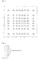
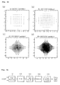
- Fig. 1 is an example of 64- Quadrature amplitude modulation (QAM) used in European DVB-T.
- QAM Quadrature amplitude modulation
- Fig. 2 is a method of Binary Reflected Gray Code (BRGC).
- BRGC Binary Reflected Gray Code
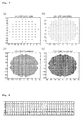
- Fig. 3 is an output close to Gaussian by modifying 64-QAM used in DVB-T.
- Fig. 4 is Hamming distance between Reflected pair in BRGC.
- Fig. 5 is characteristics in QAM where Reflected pair exists for each I axis and Q axis.
- Fig. 6 is a method of modifying QAM using Reflected pair of BRGC.
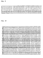
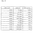
- Fig. 7 is an example of modified 64/256/1024/4096-QAM.
- Figs. 8-9 are an example of modified 64-QAM using Reflected Pair of BRGC.
- Figs. 10-11 are an example of modified 256-QAM using Reflected Pair of BRGC.
- Figs. 12-13 are an example of modified 1024-QAM using Reflected Pair of BRGC(0 ⁇ 511).
- Figs. 14-15 are an example of modified 1024-QAM using Reflected Pair of BRGC(512 ⁇ 1023).
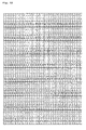
- Figs. 16-17 are an example of modified 4096-QAM using Reflected Pair of BRGC(0 ⁇ 511).
- Figs. 18-19 are an example of modified 4096-QAM using Reflected Pair of BRGC(512 ⁇ 1023).
- Figs. 20-21 are an example of modified 4096-QAM using Reflected Pair of BRGC(1024 ⁇ 1535).
- Figs. 22-23 are an example of modified 4096-QAM using Reflected Pair of BRGC(1536 ⁇ 2047).
- Figs. 24-25 are an example of modified 4096-QAM using Reflected Pair of BRGC(2048 ⁇ 2559).
- Figs. 26-27 are an example of modified 4096-QAM using Reflected Pair of BRGC(2560 ⁇ 3071).
- Figs. 28-29 are an example of modified 4096-QAM using Reflected Pair of BRGC(3072 ⁇ 3583).
- Figs. 30-31 are an example of modified 4096-QAM using Reflected Pair of BRGC(3584 ⁇ 4095).
- Fig. 32 is an example of Bit mapping of Modified-QAM where 256-QAM is modified using BRGC.
- Fig. 33 is an example of transformation of MQAM into Non-uniform constellation.
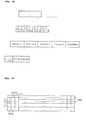
- Fig. 34 is an example of digital transmission system.
- Fig. 35 is an example of an input processor.
- Fig. 36 is an information that can be included in Base band (BB).
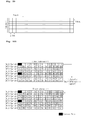
- Fig. 37 is an example of BICM.
- Fig. 38 is an example of shortened/punctured encoder.
- Fig. 39 is an example of applying various constellations.
- Fig. 40 is another example of cases where compatibility between conventional systems is considered.
- Fig. 41 is a frame structure which comprises preamble for L1 signaling and data symbol for PLP data.
- Fig. 42 is an example of frame builder.
- Fig. 43 is an example of pilot insert (404) shown in Fig. 4 .
- Fig. 44 is a structure of SP.
- Fig. 45 is a new SP structure or Pilot Pattern (PP) 5'.
- Fig. 46 is a suggested PP5' structure.
- Fig. 47 is a relationship between data symbol and preamble.
- Fig. 48 is another relationship between data symbol and preamble.
- Fig. 49 is an example of cable channel delay profile.
- Fig. 51 is an example of modulator based on OFDM.
- Fig. 52 is an example of preamble structure.
- Fig. 53 is an example of Preamble decoding.
- Fig. 54 is a process for designing more optimized preamble.
- Fig. 55 is another example of preamble structure
- Fig. 56 is another example of Preamble decoding.
- Fig. 57 is an example of Preamble structure.
- Fig. 58 is an example of L 1 decoding.
- Fig. 59 is an example of analog processor.
- Fig. 60 is an example of digital receiver system.
- Fig. 61 is an example of analog processor used at receiver.
- Fig. 62 is an example of demodulator.
- Fig. 63 is an example of frame parser.
- Fig. 64 is an example of BICM demodulator.
- Fig. 65 is an example of LDPC decoding using shortening / puncturing.
- Fig. 66 is an example of output processor.
- Fig. 67 is an example of L1 block repetition rate of 8 MHz.
- Fig. 68 is an example of L1 block repetition rate of 8 MHz.
- Fig. 69 is a new L1 block repetition rate of 7.61 MHz.
- Fig. 70 is an example of L1 signaling which is transmitted in frame header.
- Fig. 71 is preamble and L1 Structure simulation result.
- Fig. 72 is an example of symbol interleaver.
- Fig. 73 is an example of an L1 block transmission.
- Fig. 74 is another example of L 1 signaling transmitted within a frame header.
- Fig. 75 is an example of frequency or time interleaving/deinterleaving.
- Fig. 76 is a table analyzing overhead of L1 signaling which is transmitted in FECFRAME header at ModCod Header Insert (307) on data path of BICM module shown in Fig. 3 .
- Fig. 77 is showing a structure for FECFRAME header for minimizing overhead.
- Fig. 78 is showing a bit error rate (BER) performance of the aforementioned L1 protection.
- Fig. 79 is showing examples of a transmission frame and FEC frame structure.
- Fig. 80 is showing an example of L1 signaling.
- Fig. 81 is showing an example of L1-pre signaling.
- Fig. 82 is showing a structure of L1 signaling block.
- Fig. 83 is showing an L1 time interleaving.
- Fig. 84 is showing an example of extracting modulation and code information.
- Fig. 85 is showing another example of L1-pre signaling.
- Fig. 86 is showing an example of scheduling of L1 signaling block that is transmitted in preamble.
- Fig. 87 is showing an example of L1-pre signaling where power boosting is considered.
- Fig 88 is showing an example of L1 signaling.
- Fig. 89 is showing another example of extracting modulation and code information.
- Fig. 90 is showing another example of extracting modulation and code information.
- Fig. 91 is showing an example of L1-pre synchronization.
- Fig. 92 is showing an example of L1-pre signaling.
- Fig. 93 is showing an example of L1 signaling.
- Fig. 94 is showing an example of L1 signalling path.
- Fig. 95 is another example of L 1 signaling transmitted within a frame header.
- Fig. 96 is another example of L 1 signaling transmitted within a frame header.
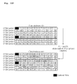
- Fig. 97 is another example of L1 signaling transmitted within a frame header.
- Fig. 98 is showing an example of L1 signaling.
- Fig. 99 is an example of symbol interleaver.
- Fig. 100 is showing an interleaving performance of time interleaver of Fig. 99 .
- Fig. 101 is an example of symbol interleaver.
- Fig. 102 is showing an interleaving performance of time interleaver of Fig. 101 .
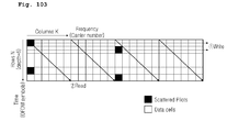
- Fig. 103 is an example of symbol deinterleaver.
- Fig. 104 is another example of time interleaving.
- Fig. 105 is a result of interleaving using method shown in Fig. 104 .
- Fig. 106 is an example of addressing method of Fig. 105 .
- Fig. 107 is another example of L 1 time interleaving.
- Fig. 108 is an example of symbol deinterleaver.
- Fig. 109 is another example of deinterleaver.
- Fig. 110 is an example of symbol deinterleaver.
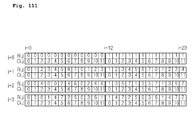
- Fig. 111 is an example of row and column addresses for time deinterleaving.
- Fig. 112 shows an example of general block interleaving in a data symbol domain where pilots are not used.
- Fig. 113 is an example of an OFDM transmitter which uses data slices.
- Fig. 114 is an example of an OFDM receiver which uses data slice.
- service is indicative of either broadcast contents which can be transmitted/received by the signal transmission/reception apparatus.
- Quadrature amplitude modulation using Binary Reflected Gray Code (BRGC) is used as modulation in a broadcasting transmission environment where conventional Bit Interleaved Coded Modulation (BICM) is used.
- BICM Bit Interleaved Coded Modulation
- Fig. 1 shows an example of 64-QAM used in European DVB-T.
- BRGC can be made using the method shown in Fig. 2 .
- An n bit BRGC can be made by adding a reverse code of (n-1) bit BRGC (i.e., reflected code) to a back of (n-1) bit, by adding 0s to a front of original (n-1) bit BRGC, and by adding 1s to a front of reflected code.
- the BRGC code made by this method has a Hamming distance between adjacent codes of one (1).
- the Hamming distance between a point and the four points which are most closely adjacent to the point is one (1) and the Hamming distance between the point and another four points which are second most closely adjacent to the point, is two (2).
- Such characteristics of Hamming distances between a specific constellation point and other adjacent points can be dubbed as Gray mapping rule in QAM.
- AWGN Additive White Gaussian Noise
- Fig. 3 shows an output close to Gaussian by modifying 64-QAM used in DVB-T.
- Such constellation can be dubbed as Non-uniform QAM (NU-QAM).
- Gaussian Cumulative Distribution Function can be used.
- QAM can be divided into two independent N-PAM.
- Gaussian CDF By dividing Gaussian CDF into N sections of identical probability and by allowing a signal point in each section to represent the section, a constellation having Gaussian distribution can be made.
- Fig. 3 is an example of transforming 64QAM of DVB-T into NU-64QAM using the above methods.
- Fig. 3 represents a result of modifying coordinates of each I axis and Q axis using the above methods and mapping the previous constellation points to newly defined coordinates.
- One embodiment of the present invention can modify QAM using BRGC by using characteristics of BRGC.
- the Hamming distance between Reflected pair in BRGC is one because it differs only in one bit which is added to the front of each code.
- Fig. 5 shows the characteristics in QAM where Reflected pair exists for each I axis and Q axis. In this figure, Reflected pair exists on each side of the dotted black line.
- an average power of a QAM constellation can be lowered while keeping Gray mapping rule in QAM.
- the minimum Euclidean distance in the constellation can be increased.
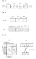
- Fig. 6 shows a method of modifying QAM using Reflected pair of BRGC.
- Fig. 6a shows a constellation and
- Fig. 6b shows a flowchart for modifying QAM using Reflected pair of BRGC.
- a target point which has the highest power among constellation points needs to be found.
- Candidate points are points where that target point can move and are the closest neighbor points of the target point's reflected pair.
- an empty point i.e., a point which is not yet taken by other points
- the power of the target point and the power of a candidate point are compared. If the power of the candidate point is smaller, the target point moves to the candidate point.
- Fig. 7 shows an example of modified 64/256/1024/4096-QAM.
- the Gray mapped values correspond to Figs. 8 ⁇ 31 respectively.
- other types of modified QAM which enables identical power optimization can be realized. This is because a target point can move to multiple candidate points.
- the suggested modified QAM can be applied to, not only the 64/256/1024/4096-QAM, but also cross QAM, a bigger size QAM, or modulations using other BRGC other than QAM.
- Fig. 32 shows an example of Bit mapping of Modified-QAM where 256-QAM is modified using BRGC.
- Fig. 32a and Fig. 32b show mapping of Most Significant Bits (MSB). Points designated as filled circles represent mappings of ones and points designated as blank circles represent mappings of zeros. In a same manner, each bit is mapped as shown in figures from (a) through (h) in Fig. 32 , until Least Significant Bits(LSB) are mapped.
- Modified-QAM can enable bit decision using only I or Q axes as conventional QAM, except for a bit which is next to MSB ( Fig. 32c and Fig. 32d ).
- a simple receiver can be made by partially modifying a receiver for QAM.
- An efficient receiver can be implemented by checking both I and Q values only when determining bit next to MSB and by calculating only I or Q for the rest of bits. This method can be applied to Approximate LLR, Exact LLR, or Hard decision.
- Non-uniform constellation or NU-MQAM can be made.
- Pj can be modified to fit MQAM.
- MQAM two PAMs having I axis and Q axis can be considered.
- the number of points changes in MQAM.
- MQAM can be transformed into Non-uniform constellation.
- Pj can be defiend as follows for the example of 256-MQAM. p j ⁇ 2.5 256 ⁇ 10 256 ⁇ 22 256 ⁇ 36 256 ⁇ 51 256 ⁇ 67 256 ⁇ 84 256 ⁇ 102 256 ⁇ 119.5 256 ⁇ 136.5 256 ⁇ 154 256 ⁇ 172 256 ⁇ 189 256 ⁇ 205 256 ⁇ 220 256 ⁇ 234 256 ⁇ 246 256 ⁇ 253.5 256
- Fig. 33 is an example of transformation of MQAM into Non-uniform constellation.
- the NU-MQAM made using these methods can retain characteristics of MQAM receivers with modified coordinates of each PAM.
- an efficient receiver can be implemented.
- a more noise-robust system than the previous NU-QAM can be implemented.
- hybridizing MQAM and NU-MQAM is possible.
- a more noise-robust system can be implemented by using MQAM for an environment where an error correction code with high code rate is used and by using NU-MQAM otherwise.
- a transmitter can let a receiver have information of code rate of an error correction code currently used and a kind of modulation currently used such that the receiver can demodulate according to the modulation currently used.
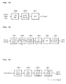
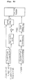
- Fig. 34 shows an example of digital transmission system.
- Inputs can comprise a number of MPEG-TS streams or GSE (General Stream Encapsulation) streams.
- An input processor module 101 can add transmission parameters to input stream and perform scheduling for a BICM module 102.
- the BICM module 102 can add redundancy and interleave data for transmission channel error correction.
- a frame builder 103 can build frames by adding physical layer signaling information and pilots.
- a modulator 104 can perform modulation on input symbols in efficient methods.
- An analog processor 105 can perform various processes for converting input digital signals into output analog signals.
- Fig. 35 shows an example of an input processor.
- Input MPEG-TS or GSE stream can be transformed by input preprocessor into a total of n streams which will be independently processed.
- Each of those streams can be either a complete TS frame which includes multiple service components or a minimum TS frame which includes service component (i.e., video or audio).
- each of those streams can be a GSE stream which transmits either multiple services or a single service.
- Input interface module 202-1 can allocate a number of input bits equal to the maximum data field capacity of a Baseband (BB) frame. A padding may be inserted to complete the LDPC/BCH code block capacity.
- the input stream sync module 203-1 can provide a mechanism to regenerate, in the receiver, the clock of the Transport Stream (or packetized Generic Stream), in order to guarantee end-to-end constant bit rates and delay.
- the input Transport Streams are delayed by delay compensators 204-1 ⁇ n considering interleaving parameters of the data PLPs in a group and the corresponding common PLP.
- Null packet deleting modules 205-1 ⁇ n can increase transmission efficiency by removing inserted null packet for a case of VBR (variable bit rate) service.
- Cyclic Redundancy Check (CRC) encoder modules 206-1 ⁇ n can add CRC parity to increase transmission reliability of BB frame.
- BB header inserting modules 207-1 ⁇ n can add BB frame header at a beginning portion of BB frame. Information that can be included in BB header is shown in Fig. 36 .
- a Merger/slicer module 208 can perform BB frame slicing from each PLP, merging BB frames from multiple PLPs, and scheduling each BB frame within a transmission frame. Therefore, the merger/slicer module 208 can output L1 signaling information which relates to allocation of PLP in frame.
- a BB scrambler module 209 can randomize input bitstreams to minimize correlation between bits within bitstreams.
- the modules in shadow in Fig. 35 are modules used when transmission system uses a single PLP, the other modules in Fig. 35 are modules used when the transmission device uses multiple PLPs.
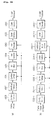
- Fig. 37 shows an example of BICM module.
- Fig. 37a shows data path and Fig. 37b shows L1 path of BICM module.
- An outer coder module 301 and an inner coder module 303 can add redundancy to input bitstreams for error correction.
- An outer interleaver module 302 and an inner interleaver module 304 can interleave bits to prevent burst error.
- the Outer interleaver module 302 can be omitted if the BICM is specifically for DVB-C2.
- a bit demux module 305 can control reliability of each bit output from the inner interleaver module 304.
- a symbol mapper module 306 can map input bitstreams into symbol streams.
- Case 1 shows an example of using only NU-MQAM at low code rate for simplified system implementation.
- Case 2 shows an example of using optimized constellation at each code rate.
- the transmitter can send information about the code rate of the error correction code and the constellation capacity to the receiver such that the receiver can use an appropriate constellation.
- Fig. 40 shows another example of cases where compatibility between conventional systems is considered. In addition to the examples, further combinations for optimizing the system are possible.
- the ModCod Header inserting module 307 shown in Fig. 37 can take Adaptive coding and modulation (ACM)/Variable coding and modulation (VCM) feedback information and add parameter information used in coding and modulation to a FEC block as header.
- ACM Adaptive coding and modulation
- VCM Variariable coding and modulation
- the Modulation type/Coderate (ModCod) header can include the following information:
- the Symbol interleaver module 308 can perform interleaving in symbol domain to obtain additional interleaving effects. Similar processes performed on data path can be performed on L1 signaling path but with possibly different parameters (301-1 ⁇ 308-1). At this point, a shortened/punctured code module (303-1) can be used for inner code.
- Fig. 38 shows an example of LDPC encoding using shortening / puncturing.
- Shortening process can be performed on input blocks which have less bits than a required number of bits for LDPC encoding as many zero bits required for LDPC encoding can be padded (301c).
- Zero Padded input bitstreams can have parity bits through LDPC encoding (302c).
- bitstreams that correspond to original bitstreams zeros can be removed (303c) and for parity bitstreams, puncturing (304c) can be performed according to code-rates.
- These processed information bitstreams and parity bitstreams can be multiplexed into original sequences and outputted (305c).
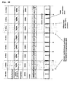
- Fig. 41 shows a frame structure which comprises preamble for L1 signaling and data symbol for PLP data. It can be seen that preamble and data symbols are cyclically generated, using one frame as a unit. Data symbols comprise PLP type 0 which is transmitted using a fixed modulation/coding and PLP type 1 which is transmitted using a variable modulation/coding. For PLP type 0, information such as modulation, FEC type, and FEC code rate are transmitted in preamble (see Fig. 42 Frame header insert 401). For PLP type 1, corresponding information can be transmitted in FEC block header of a data symbol (see Fig. 37 ModCod header insert 307).
- ModCod overhead can be reduced by 3 ⁇ 4% from a total transmission rate, for PLP type0 which is transmitted at a fixed bit rate.
- Frame header remover r401 shown in Fig. 63 can extract information on Modulation and FEC code rate and provide the extracted information to a BICM decoding module.
- ModCod extracting modules, r307 and r307-1 shown in Fig. 64 can extract and provide the parameters necessary for BICM decoding.
- Fig. 42 shows an example of a frame builder.
- a frame header inserting module 401 can form a frame from input symbol streams and can add frame header at front of each transmitted frame.
- the frame header can include the following information:
- Channel bonding environment is assumed for L1 information transmitted in Frame header and data that correspond to each data slice is defined as PLP. Therefore, information such as PLP identifier, channel bonding identifier, and PLP start address are required for each channel used in bonding.
- PLP identifier e.g., a PLP type supports variable modulation/coding
- ModCod field in Frame header if PLP type supports fixed modulation/coding to reduce signaling overhead.
- a Notch band exists for each PLP, by transmitting the start address of the Notch and its width, decoding corresponding carriers at the receiver can become unnecessary.
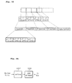
- Fig. 43 shows an example of Pilot Pattern 5 (PP5) applied in a channel bonding environment. As shown, if SP positions are coincident with preamble pilot positions, irregular pilot structure can occur.
- PP5 Pilot Pattern 5
- Fig. 43a shows an example of pilot inserting module 404 as shown in Fig. 42 .
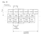
- a single frequency band for example, 8 MHz
- the available bandwidth is 7.61 MHz, but if multiple frequency bands are bonded, guard bands can be removed, thus, frequency efficiency can increase greatly.
- Fig. 43b is an example of preamble inserting module 504 as shown in Fig. 51 that is transmitted at the front part of the frame and even with channel bonding, the preamble has repetition rate of 7.61 MHz, which is bandwidth of L1 block. This is a structure considering the bandwidth of a tuner which performs initial channel scanning.
- Pilot Patterns exist for both Preamble and Data Symbols.
- scattered pilot (SP) patterns can be used.
- Pilot Pattern 5 (PP5) and Pilot Pattern 7 (PP7) of T2 can be good candidates for frequency-only interpolation.
- Pilot patterns for preamble can cover all possible pilot positions for initial channel acquisition.
- preamble pilot positions should be coincident with SP positions and a single pilot pattern for both the preamble and the SP is desired.
- Preamble pilots could also be used for time-interpolation and every preamble could have an identical pilot pattern. These requirements are important for C2 detection in scanning and necessary for frequency offset estimation with scrambling sequence correlation. In a channel bonding environment, the coincidence in pilot positions should also be kept for channel bonding because irregular pilot structure may degrade interpolation performance.
- GI guard interval
- preamble pilot positions can be coincident with every SP positions of data symbol.
- data slice where a service is transmitted can be determined regardless of 8 MHz bandwidth granularity.
- transmission starting from SP position and ending at SP position can be chosen.
- channel estimation module r501 shown in Fig. 62 can perform time interpolation to obtain pilots shown in dotted lines in Fig. 43 and perform frequency interpolation.
- time interpolation to obtain pilots shown in dotted lines in Fig. 43 and perform frequency interpolation.
- intervals for non-continuous points of which intervals are designated as 32 in Fig. 43 , either performing interpolations on left and right separately or performing interpolations on only one side then performing interpolation on the other side by using the already interpolated pilot positions of which interval is 12 as a reference point can be implemented.
- data slice width can vary within 7.61 MHz, thus, a receiver can minimize power consumption by performing channel estimation and decoding only necessary subcarriers.
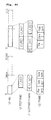
- Fig. 44 shows another example of PP5 applied in channel bonding environment or a structure of SP for maintaining effective distance x as 12 to avoid irregular SP structure shown in Fig. 43 when channel bonding is used.
- Fig. 44a is a structure of SP for data symbol and
- Fig. 44b is a structure of SP for preamble symbol.
- the proposed new SP patterns can be advantageous in that single SP pattern can be used for both single and bonded channel; no irregular pilot structure can be caused, thus a good channel estimation is possible; both preamble and SP pilot positions can be kept coincident; pilot density can be kept the same as for PP5 and PP7 respectively; and Frequency-only interpolation capability can also be preserved.
- preamble structure can meet the requirements such as preamble pilot positions should cover all possible SP positions for initial channel acquisition; maximum number of carriers should be 3409 (7.61 MHz) for initial scanning; exactly same pilot patterns and scrambling sequence should be used for C2 detection; and no detection-specific preamble like P1 in T2 is required.
- data slice position granularity may be modified to 16 carriers rather than 12, thus, less position addressing overhead can occur and no other problem regarding data slice condition, Null slot condition etc can be expected.
- pilots in every preamble can be used when time interpolation of SP of data symbol is performed. Therefore, channel acquisition and channel estimation at the frame boundaries can be improved.
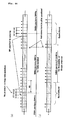
- Fig. 47 shows a relationship between data symbol and preamble when preamble structures as shown in Fig. 52 and Fig. 53 are used.
- L1 block can be repeated by period of 6 MHz.
- For L1 decoding both frequency offset and Preamble shift pattern should be found. L1 decoding is not possible in arbitrary tuner position without channel bonding information and a receiver cannot differentiate between preamble shift value and frequency offset.
- a receiver specifically for Frame header remover r401 shown in Fig. 63 to perform L1 signal decoding, channel bonding structure needs to be obtained. Because preamble shift amount expected at two vertically shadowed regions in Fig. 47 is known, time/freq synchronizing module r505 in Fig. 62 can estimate carrier frequency offset. Based on the estimation, L1 signaling path (r308-1 ⁇ r301-1) in Fig. 64 can decode L1.
- Fig. 48 shows a relationship between data symbol and preamble when the preamble structure as shown in Fig. 55 is used.
- L 1 block can be repeated by period of 8 MHz.
- Frequency offset can be easily estimated by using known Pseudo Random Binary Sequence (PRBS) sequence.
- PRBS Pseudo Random Binary Sequence
- preamble and data symbols are aligned, thus, additional sync search can become unnecessary. Therefore, for a receiver, specifically for the Frame header remover module r401 shown in Fig. 63 , it is possible that only correlation peak with pilot scrambling sequence needs to be obtained to perform L1 signal decoding.
- the time/freq synchronizing module r505 in Fig. 62 can estimate carrier frequency offset from peak position.
- Fig. 49 shows an example of cable channel delay profile.
- Slightly less delay coverage may not be an important in cable channel. For example, it can be 8 us for PP5' and 4 ⁇ s for PP7' compared to 9.3 ⁇ s (PP5) and 4.7 ⁇ s (PP7). Meaningful delays can be covered by both pilot patterns even in a worst case. For preamble pilot position, no more than all SP positions in data symbol are necessary.
- Edge carriers could be inserted for closing edge.
- channel estimation module r501 in Fig. 62 can perform channel estimation using interpolation on preamble and data symbols because no irregular pilot pattern can occur, regardless of window position which is decided by data slice locations. At this time, using only frequency interpolation can be enough to compensate channel distortion from delay spread. If time interpolation is performed additionally, more accurate channel estimation can be performed.
- pilot position and pattern can be repeated based on a period of 8 MHz.
- a single pilot pattern can be used for both preamble and data symbols. L1 decoding can always be possible without channel bonding knowledge.
- the proposed pilot pattern may not affect commonality with T2 because the same pilot strategy of scattered pilot pattern can be used; T2 already uses 8 different pilot patterns; and no significant receiver complexity can be increased by modified pilot patterns.
- the period of PRBS can be 2047 (m-sequence); PRBS generation can be reset every 8 MHz, of which the period is 3584; pilot repetition rate of 56 can be also co-prime with 2047; and no PAPR issue can be expected.
- Fig. 51 shows an example of a modulator based on OFDM.
- Input symbol streams can be transformed into time domain by IFFT module 501.
- PAPR peak-to-average power ratio
- ACE Active constellation extension
- GI inserting module 503 can copy a last part of effective OFDM symbol to fill guard interval in a form of cyclic prefix.
- Preamble inserting module 504 can insert preamble at the front of each transmitted frame such that a receiver can detect digital signal, frame and acquire time/freq offset acquisition. At this time, the preamble signal can perform physical layer signaling such as FFT size (3 bits) and Guard interval size (3 bits). The Preamble inserting module 504 can be omitted if the modulator is specifically for DVB-C2.
- Fig. 52 shows an example of a preamble structure for channel bonding, generated at preamble inserting module 504 in Fig. 51 .
- One complete L1 block should be "always decodable" in any arbitrary 7.61 MHz tuning window position and no loss of L1 signaling regardless of tuner window position should occur.
- L1 blocks can be repeated in frequency domain by period of 6 MHz. Data symbol can be channel bonded for every 8 MHz.
- a receiver uses a tuner such as the tuner r603 represented in Fig. 61 which uses a bandwidth of 7.61 MHz
- the Frame header remover r401 in Fig. 63 needs to rearrange the received cyclic shifted L1 block ( Fig. 53 ) to its original form. This rearrangement is possible because L1 block is repeated for every 6MHz block.
- Fig. 53a can be reordered into Fig. 53b .
- Fig. 54 shows a process for designing a more optimized preamble.
- the preamble structure of Fig. 52 uses only 6MHz of total tuner bandwidth 7.61 MHz for L 1 decoding. In terms of spectrum efficiency, tuner bandwidth of 7.61 MHz is not fully utilized. Therefore, there can be further optimization in spectrum efficiency.
- Fig. 55 shows another example of preamble structure or preamble symbols structure for full spectrum efficiency, generated at Frame Header Inserting module 401 in Fig. 42 .
- L1 blocks can be repeated in frequency domain by period of 8 MHz.
- One complete L1 block is still "always decodable" in any arbitrary 7.61 MHz tuning window position. After tuning, the 7.61 MHz data can be regarded as a virtually punctured code. Having exactly the same bandwidth for both the preamble and data symbols and exactly the same pilot structure for both the preamble and data symbols can maximize spectrum efficiency.
- Other features such as cyclic shifted property and not sending L1 block in case of no data slice can be kept unchanged.
- the bandwidth of preamble symbols can be identical with the bandwidth of data symbols or, as shown in Fig. 57 , the bandwidth of the preamble symbols can be the bandwidth of the tuner (here, it's 7.61 MHz).
- the tuner bandwidth can be defined as a bandwidth that corresponds to a number of total active carriers when a single channel is used. That is, the bandwidth of the preamble symbol can correspond to the number of total active carriers (here, it's 7.61 MHz).
- Fig. 56 shows a virtually punctured code.
- the 7.61 MHz data among the 8 MHz L 1 block can be considered as punctured coded.
- Frame header remover r401 in Fig. 63 needs to rearrange received, cyclic shifted L1 block into original form as shown in Fig. 56 .
- L1 decoding is performed using the entire bandwidth of the tuner.
- a spectrum of the rearranged L 1 block can have a blank region within the spectrum as shown in upper right side of Fig. 56 because an original size of L1 block is 8 MHz bandwidth.
- the block can have a form which appears to be punctured as shown in lower right side of Fig. 56 .
- This L1 block can be decoded at the punctured/shortened decode module r303-1 in Fig. 64 .
- the entire tuner bandwidth can be utilized, thus spectrum efficiency and coding gain can be increased.
- an identical bandwidth and pilot structure can be used for the preamble and data symbols.
- the preamble bandwidth or the preamble symbols bandwidth is set as a tuner bandwidth as shown in Fig. 58 , (it's 7.61 MHz in the example), a complete L1 block can be obtained after rearrangement even without puncturing.
- the L 1 block has 3408 active subcarriers and the 3408 active subcarriers correspond to 7.61 MHz of 8MHz Radio Frequency (RF) band.
- RF Radio Frequency
- decoding can be performed at punctured/shortened decode module r303-1 in Fig. 64 , after performing only deinterleaving in the symbol domain.
- the proposed new preamble structure can be advantageous in that it's fully compatible with previously used preamble except that the bandwidth is different; L1 blocks are repeated by period of 8 MHz; L1 block can be always decodable regardless of tuner window position; Full tuner bandwidth can be used for L1 decoding; maximum spectrum efficiency can guarantee more coding gain; incomplete L1 block can be considered as punctured coded; simple and same pilot structure can be used for both preamble and data; and identical bandwidth can be used for both preamble and data.
- Fig. 59 shows an example of an analog processor.
- a DAC module 601 can convert digital signal input into analog signal. After transmission frequency bandwidth is up-converted (602) and analog filtered (603) signal can be transmitted.
- Fig. 60 shows an example of a digital receiver system.
- Received signal is converted into digital signal at an analog process module r105.
- a demodulator r104 can convert the signal into data in frequency domain.
- a frame parser r103 can remove pilots and headers and enable selection of service information that needs to be decoded.
- a BICM demodulator r102 can correct errors in the transmission channel.
- An output processor r101 can restore the originally transmitted service stream and timing information.
- Fig. 61 shows an example of analog processor used at the receiver.
- a Tuner/AGC module r603 can select desired frequency bandwidth from received signal.
- a down converting module r602 can restore baseband.
- An ADC module r601 can convert analog signal into digital signal.
- Fig. 62 shows an example of demodulator.
- a frame detecting module r506 can detect the preamble, check if a corresponding digital signal exists, and detect a start of a frame.
- a time/freq synchronizing module r505 can perform synchronization in time and frequency domains. At this time, for time domain synchronization, a guard interval correlation can be used. For frequency domain synchronization, correlation can be used or offset can be estimated from phase information of a subcarrier that is transmitted in the frequency domain.
- a preamble removing module r504 can remove preamble from the front of detected frame.
- a GI removing module r503 can remove guard interval.
- a FFT module r501 can transform signal in the time domain into signal in the frequency domain.
- a channel estimation/equalization module r501 can compensate errors by estimating distortion in transmission channel using pilot symbol.
- the Preamble removing module r504 can be omitted if the demodulator is specifically for DVB
- Fig. 63 shows an example of frame parser.
- a pilot removing module r404 can remove pilot symbol.
- a freq deinterleaving module r403 can perform deinterleaving in the frequency domain.
- An OFDM symbol merger r402 can restore data frame from symbol streams transmitted in OFDM symbols.
- a frame header removing module r401 can extract physical layer signaling from header of each transmitted frame and remove header. Extracted information can be used as parameters for following processes in the receiver.
- Fig. 64 shows an example of a BICM demodulator.
- Fig. 64a shows a data path and
- Fig. 64b shows a L1 signaling path.
- a symbol deinterleaver r308 can perform deinterleaving in the symbol domain.
- a ModCod extract r307 can extract ModCod parameters from front of each BB frame and make the parameters available for following adaptive/variable demodulation and decoding processes.
- a Symbol demapper r306 can demap input symbol streams into bit Log-Likelyhood Ratio (LLR) streams.
- the Output bit LLR streams can be calculated by using a constellation used in a Symbol mapper 306 of the transmitter as reference point.
- LLR Log-Likelyhood Ratio
- the Symbol demapper r306 of the receiver can obtain a constellation using the code rate and constellation capacity information transmitted from the transmitter.
- the bit mux r305 of the receiver can perform an inverse function of the bit demux 305 of the transmitter.
- the Inner deinterleaver r304 and outer deinterleaver r302 of the receiver can perform inverse functions of the inner interleaver 304 and outer interleaver 302 of the transmitter, respectively to get the bitstream in its original sequence.
- the outer deinterleaver r302 can be omitted if the BICM demodulator is specifically for DVB-C2.
- the inner decoder r303 and outer decoder r301 of the receiver can perform corresponding decoding processes to the inner coder 303 and outer code 301 of the transmitter, respectively, to correct errors in the transmission channel. Similar processes performed on data path can be performed on L1 signaling path, but with different parameters (r308-1 ⁇ r301-1). At this point, as explained in the preamble part, a shortened/punctured code module r303-1 can be used for L 1 signal decoding.
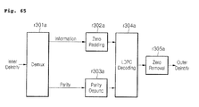
- Fig. 65 shows an example of LDPC decoding using shortening / puncturing.
- a demux r301a can separately output information part and parity part of systematic code from input bit streams.
- a zero padding (r302a) can be performed according to a number of input bit streams of LDPC decoder, for the parity part, input bit streams for (r303a) the LDPC decoder can be generated by de-puncturing punctured part.
- LDPC decoding (r304a) can be performed on generated bit streams, zeros in information part can be removed and output (r305a).
- Fig. 66 shows an example of output processor.
- a BB descrambler r209 can restore scrambled (209) bit streams at the transmitter.
- a Splitter r208 can restore BB frames that correspond to multiple PLP that are multiplexed and transmitted from the transmitter according to PLP path.
- a BB header remover r207-1 ⁇ n can remove the header that is transmitted at the front of the BB frame.
- a CRC decoder r206-1 ⁇ n can perform CRC decoding and make reliable BB frames available for selection.
- a Null packet inserting modules r205-1 ⁇ n can restore null packets which were removed for higher transmission efficiency in their original location.
- a Delay recovering modules r204-1 ⁇ n can restore a delay that exists between each PLP path.
- An output clock recovering modules r203-1 ⁇ n can restore the original timing of the service stream from timing information transmitted from the input stream synchronization modules 203-1 ⁇ n.
- An output interface modules r202-1 ⁇ n can restore data in TS/GS packet from input bit streams that are sliced in BB frame.
- An output postprocess modules r201-1 ⁇ n can restore multiple TS/GS streams into a complete TS/GS stream, if necessary.
- the shaded blocks shown in Fig. 66 represent modules that can be used when a single PLP is processed at a time and the rest of the blocks represent modules that can be used when multiple PLPs are processed at the same time.
- Preamble pilot patterns were carefully designed to avoid PAPR increase, thus, whether L1 repetition rate may increase PAPR needs to be considered.
- the number of L1 information bits varies dynamically according to the channel bonding, the number of PLPs, etc. In detail, it is necessary to consider things such as fixed L1 block size may introduce unnecessary overhead; L 1 signaling should be protected more strongly than data symbols; and time interleaving of L1 block can improve robustness over channel impairment such as impulsive noise need.
- Fig. 69 shows a new L1 block repetition rate of 7.61 MHz or full tuner bandwidth.
- a full spectrum efficiency (26.8% BW increase) can be obtained with no virtual puncturing.
- 4K-FFT DVB-T2 frequency interleaving can be used for commonality and the same pattern can repeat itself by period of about 1704 MHz after interleaving.
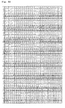
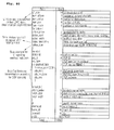
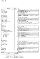
- Fig. 70 is an example of L1 signaling which is transmitted in the frame header.
- Each information in L1 signaling can be transmitted to the receiver and can be used as a decoding parameter.
- the information can be used in L1 signal path shown in Fig. 64 and PLPs can be transmitted in each data slice. An increased robustness for each PLP can be obtained.
- Fig. 72 is an example of a symbol interleaver 308-1 as shown in L1 signaling path in Fig. 37 and also can be an example of its corresponding symbol deinterleaver r308-1 as shown in L1 signaling path in Fig. 64 .
- Blocks with tilted lines represent L1 blocks and solid blocks represent data carriers.
- L 1 blocks can be transmitted not only within a single preamble, but also can be transmitted within multiple OFDM blocks.
- the size of the interleaving block can vary. In other words, num_L1_sym and L1 span can be different from each other.
- data can be transmitted within the rest of the carriers of the OFDM symbols where the L1 block is transmitted. At this point, full spectrum efficiency can be guaranteed because the repeating cycle of L1 block is still a full tuner bandwidth.
- the numbers in blocks with tilted lines represent the bit order within a single LDPC block.
- a block interleaving effect can be obtained.
- one LDPC block can be interleaved in the time domain and the frequency domain and then can be transmitted.
- Num_L1_sym can be a predetermined value, for example, a number between 2 ⁇ 4 can be set as a number of OFDM symbols.
- a punctured/shortened LDPC code having a minimum length of the codeword can be used for L1 protection.
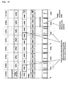
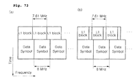
- Fig. 73 is an example of an L1 block transmission.
- Fig. 73 illustrates Fig. 72 in frame domain.
- L1 blocks can be spanning in full tuner bandwidth or as shown on Fig. 73b , L1 blocks can be partially spanned and the rest of the carriers can be used for data carrier. In either case, it can be seen that the repetition rate of L1 block can be identical to a full tuner bandwidth.
- OFDM symbols which uses L1 signaling including preamble only symbol interleaving can be performed while not allowing data transmission in that OFDM symbols. Consequently, for OFDM symbol used for L1 signaling, a receiver can decode L1 by performing deinterleaving without data decoding.
- the L 1 block can transmit L 1 signaling of current frame or L 1 signaling of a subsequent frame.
- L1 parameters decoded from L1 signaling decoding path shown in Fig. 64 can be used for decoding process for data path from frame parser of subsequent frame.
- interleaving blocks of L 1 region can be performed by writing blocks to a memory in a row direction and reading the written blocks from the memory in a column direction.
- deinterleaving blocks of L1 region can be performed by writing blocks to a memory in a column direction and reading the written blocks from the memory in a row direction.
- the reading and writing directions of transmitter and receiver can be interchanged.
- L1 signaling efficient signaling structure can allow maximum configuration in an environment of 8 channels bonding, 32 notches, 256 data slices, and 256 PLPs.
- L1 block structure flexible L1 signaling can be implemented according to L1 block size. Time interleaving can be performed for better robustness for T2 commonality. Less overhead can allow data transmission in preamble.
- Block interleaving of L1 block can be performed for better robustness.
- the interleaving can be performed with fixed pre-defined number of L1 symbols (num_L1_sym) and a number of carriers spanned by L 1 as a parameter (L1_span).
- the same technique is used for P2 preamble interleaving in DVB-T2.
- L1 block of variable size can be used. Size can be adaptable to the amount of L1 signaling bits, resulting in a reduced overhead. Full spectrum efficiency can be obtained with no PAPR issue. Less than 7.61 MHz repetition can mean thatmore redundancy can be sent but unused. No PAPR issue can arise because of 7.61 MHz repetition rate for L 1 block.
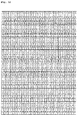
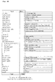
- Fig. 74 is another example of L1 signaling transmitted within a frame header.
- This Fig. 74 is different from Fig. 70 in that the L1_span field having 12 bits it is divided into two fields.
- the L1_span field is divided into a L1_column having 9 bits and a L1_row having 3 bits.
- the L1_column represents the carrier index that L1 spans. Because data slice starts and ends at every 12 carriers, which is the pilot density, the 12 bits of overhead can be reduced by 3 bits to reach 9 bits.
- L1_row represents the number of OFDM symbols where L1 is spanning when time interleaving is applied. Consequently, time interleaving can be performed within an area of L1_columns multiplied by L1_rows.
- a total size of L1 blocks can be transmitted such that L1_span shown in Fig. 70 can be used when time interleaving is not performed.
- L1 block size is 11,776 x 2 bits in the example, thus 15 bits is enough. Consequently, the L1_span field can be made up of 15 bits.
- Fig. 75 is an example of frequency or time interleaving/deinterleaving.
- the Fig. 75 shows a part of a whole transmission frame.
- the Fig. 75 also shows bonding of multiple 8 MHz bandwidths.
- a frame can consist of a preamble which transmits L1 blocks and a data symbol which transmits data.
- the different kinds of data symbols represent data slices for different services.
- the preamble transmits L1 blocks for every 7.61 MHz.
- frequency or time interleaving is performed within L1 blocks and not performed between L1 blocks. That is, for the preamble, it can be said that interleaving is performed at L1 block level. This allows decoding the L1 blocks by transmitting L1 blocks within a tuner window bandwidth even when the tuner window has moved to a random location within a channel bonding system.
- a symbol interleaver 308 in a data path of a BICM module of transmitter as shown in Fig. 37 can perform symbol interleaving for each data slice.
- a symbol interleaver 308-1 in an L1 signal path can perform symbol interleaving for each L1 block.
- a frequency interleaver 403 shown in Fig. 42 needs to perform interleaving on the preamble and data symbols separately. Specifically, for the preamble, frequency interleaving can be performed for each L1 block and for data symbol, frequency interleaving can be performed for each data slice. At this point, time interleaving in data path or L1 signal path may not be performed considering low latency mode.
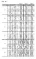
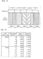
- Fig. 76 is a table analyzing overhead of L1 signaling which is transmitted in a FECFRAME header at the ModCod Header Inserting module 307 on the data path of the BICM module as shown in Fig. 37 .
- a maximum overhead of 3.3% can occur which may not be negligible.
- 45 symbols are assumed for FECFRAME protection and the preamble is a C2 frame specific L1 signaling and FECFRAME header is FECFRAME specific L1 signaling i.e., Mod, Cod, and PLP identifier.
- ACM/VCM type and multiple PLP cases frame can be kept same as for the FECFRAME header.
- the PLP identifier can be removed from the FECFRAME header, resulting in up to 1.8% overhead reduction.
- the Mod/Cod field can be removed from the FECFRAME header, resulting in up to 1.5% overhead reduction.
- no FECFRAME header is required, thus, up to 3.3% of overhead reduction can be obtained.
- Mod/Cod 7 bits
- PLP identifier 8 bits
- PLPs can be aligned with the C2 transmission frame; every ModCod of each PLP can be known from the preamble; and a simple calculation can enable synchronization with the specific FECFRAME.
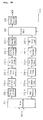
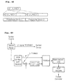
- Fig. 77 is showing a structure for a FECFRAME header for minimizing the overhead.
- the blocks with tilted lines and the FECFRAME Builder represent a detail block diagram of the ModCod Header Inserting module 307 on data path of the BICM module as shown in Fig. 37 .
- the solid blocks represent an example of inner coding module 303, inner interleaver 304, bit demux 305, and symbol mapper 306 on the data path of the BICM module as shown in Fig. 37 .
- shortened L1 signaling can be performed because CCM does not require a Mod/Cod field and single PLP does not require a PLP identifier.
- the LI signal can be repeated three times in the preamble and BPSK modulation can be performed, thus, a very robust signaling is possible.
- the ModCod Header Inserting module 307 can insert the generated header into each FEC frame.
- Fig. 84 is showing an example of the ModCod extracting module r307 on the data path of BICM demod module shown in Fig. 64 .
- the FECFRAME header can be parsed (r301b), then symbols which transmit identical information in repeated symbols can be delayed, aligned, and then combined (Rake combining r302b). Finally, when BPSK demodulation (r303b) is performed, received L1 signal field can be restored and this restored L1 signal field can be sent to the system controller to be used as parameters for decoding. Parsed FECFRAME can be sent to the symbol demapper.
- Fig. 79 is showing examples of transmission frames and FEC frame structures.
- the FEC frame structures shown on the upper right side of the Fig. 79 represent FECFRAME header inserted by the ModCod Header Inserting module 307 in Fig. 37 . It can be seen that depending on various combinations of conditions i.e., CCM or ACM/VCM type and single or multiple PLP, different size of headers can be inserted. Or, no header can be inserted.
- Transmission frames formed according to data slice types and shown on the lower left side of the Fig. 79 can be formed by the Frame header inserting module 401 of the Frame builder as shown in Fig. 42 and the merger/slicer module 208 of the input processor shown in Fig. 35 .
- the FECFRAME can be transmitted according to different types of data slice. Using this method, a maximum of 3.3% of overhead can be reduced.
- a maximum of 3.3% of overhead can be reduced.
- four different types of structures are shown, but a skilled person in the art would understand that these are only examples, and any of these types or their combinations can be used for the data slice.
- the Frame header removing module r401 of the Frame parser module as shown in Fig. 63 and the ModCod extracting module r307 of the BICM demod module shown in Fig. 64 can extract a ModCod field parameter which is required for decoding.
- the data slice types of transmission frame parameters can be extracted. For example, for CCM type, parameters can be extracted from L1 signaling which is transmitted in the preamble and for ACM/VCM type, parameters can be extracted from the FECFRAME header.
- the fecframe structure can be divided into two groups, in which the first group is the upper three frame structures with header and the second group is the last frame structure without header.
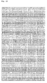
- Fig. 80 is showing an example of L1 signaling which can be transmitted within the preamble by the Frame header inserting module 401 of the Frame builder module shown in Fig. 42 .
- This L1 signaling is different from the previous L1 signaling in that L1 block size can be transmitted in bits (L1_size, 14 bits); turning on/off time interleaving on data slice is possible (dslice_time_intrlv, 1 bit); and by defining data slice type (dslice_type, 1 bit), L1 signaling overhead is reduced.
- the Mod/Cod field can be transmitted within the preamble rather than within the FECFRAME header (plp_mod (3 bits), plp_fec_type (1 bit), plp_cod (3 bits)).
- the shortened/punctured inner decoder r303-1 of the BICM demod as shown in Fig. 64 can obtain the first LDPC block, which has a fixed L1 block size, transmitted within the preamble, through decoding.
- the numbers and size of the rest of the LDPC blocks can also be obtained.
- Time interleaving can be used when multiple OFDM symbols are needed for L1 transmission or when there is a time-interleaved data slice.
- a flexible on/off of the time interleaving is possible with an interleaving flag.
- a time interleaving flag (1 bit) and a number of OFDM symbols interleaved (3 bits) may be required, thus, a total of 4 bits can be protected by a way similar to a shortened FECFRAME header.
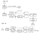
- Fig. 81 is showing an example of L1-pre signaling that can be performed at the ModCod Header Inserting module 307-1 on the data path of BICM module shown in Fig. 37 .
- the blocks with tilted lines and Preamble Builder are examples of the ModCod Header Inserting module 307-1 on the L1 signaling path of the BICM module shown in Fig. 37 .
- the solid blocks are examples of the Frame header inserting module 401 of the Frame builder as shown in Fig. 42 .
- the solid blocks can be examples of shortened/punctured inner code module 303-1, inner interleaver 304-1, bit demux 305-1, and symbol mapper 306-1 on L1 signaling path of BICM module shown in Fig. 37 .
- the L1 signal that is transmitted in the preamble can be protected using shortened/punctured LDPC encoding.
- Related parameters can be inserted into the Header in a form of L1-pre.
- time interleaving parameters can be transmitted in the Header of the preamble.
- a four times repetition can be performed.
- the ModCod extracting module r307-1 on the L1 signaling path of BICM demod as shown in Fig. 64 needs to use the decoding module shown in Fig. 84 .
- a Rake receiving process which synchronizes the four times repeated symbols and adding the symbols, is required.
- Fig. 82 shows a structure of L1 the signaling block that is transmitted from the Frame header inserting module 401 of the Frame builder module as shown in Fig. 42 . It is showing a case where no time interleaving is used in a preamble.
- different kind of LDPC blocks can be transmitted in the order of the carriers. Once an OFDM symbol is formed and transmitted then a following OFDM symbol is formed and transmitted. For the last OFDM symbol to be transmitted, if there is any carrier left, that carriers can be used for data transmission or can be dummy padded.
- the example in Fig. 82 shows a preamble that comprises three OFDM symbol.
- the symbol deinterleaver r308-1 on the L1 signaling path of BICM demodulator as shown in Fig. 64 can be skipped.
- Fig. 83 shows a case where L1 time interleaving is performed.
- block interleaving can be performed in a fashion of forming an OFDM symbol for identical carrier indices then forming an OFDM symbols for the next carrier indices.
- no interleaving if there is any carrier left, that carriers can be used for data transmission or can be dummy padded.
- the symbol deinterleaver r308-1 on the L1 signaling path of the BICM demodulator shown in Fig. 64 can perform block deinterleaving by reading LDPC blocks in increasing order of numbers of the LDPC blocks.
- XFECFrame means XFEC(compleX Forward Error Correction)Frame and mod/cod means modulation type/coderate.
- a frame parser can form a frame from demodulated signals.
- the frame has data symbols and the data symbols can have a first type of data slice which has an XFECFrame and an XFECFrame header and a second type of data slice which has XFECFrame without XFECFrame header.
- a receiver can extract a field for indicating whether to perform time de-interleaving on the preamble symbols or not to perform time de-interleaving on the preamble symbols, from the L1 of the preamble symbols.
- a frame builder can build a frame.
- Data symbols of the frame comprise a first type of data slice which has an XFECFrame and an XFECFrame header and a second type of data slice which has XFECFrame without XFECFrame header.
- a field for indicating whether to perform time interleaving on preamble symbols or not to perform time interleaving on preamble symbols can be inserted in L1 of the preamble symbols.
- a minimum size of codeword that can obtain coding gain can be determined and can be transmitted in a first LDPC block. In this manner, for the rest of LDPC block sizes can be obtained from that transmitted L1 block size.
- Fig. 85 is showing another example of L1-pre signaling that can be transmitted from ModCod Header Inserting module 307-1 on L1 signalinig path of BICM module shown in Fig. 37 .
- Fig. 85 is different from Fig. 81 in that Header part protection mechanism has been modified.
- L1 block size information L1_size (14 bits) is not transmitted in L1 block, but transmitted in Header.
- time interleaving information of 4 bits can be transmitted too.
- BCH (45, 18) code which outputs 45 bits are used and copied to the two paths and finally, QPSK mapped.
- time interleaving depth is set as a number of preambles that is required to transmit L1 block, L1_span (3bits) that indicates time interleaving depth may not need to be transmitted. In other words, only time interleaving on/off flag (1 bit) can be transmitted.
- time deinterleaving depth can be obtained.
- Fig. 86 is showing an example of scheduling of L1 signaling block that is transmitted in preamble. If a size of L1 information that can be transmitted in a preamble is Nmax, when L1 size is smaller than Nmax, one preamble can transmit the information. However, when L1 size is bigger than Nmax, L1 information can be equally divided such that the divided L1 sub-block is smaller than Nmax, then the divided L1 sub-block can be transmitted in a preamble. At this point, for a carrier that is not used because of L1 information being smaller than Nmax, no data are transmitted.
- power of carriers where L1 block are transmitted can be boosted up to maintain a total preamble signal power equal to data symbol power.
- Power boosting factor can be varied depending on transmitted L1 size and a transmitter and a receiver can have a set value of this power boosting factor. For example, if only a half of total carriers are used, power boosting factor can be two.
- Fig. 87 is showing an example of L1-pre signaling where power boosting is considered. When compared to Fig. 85 , it can be seen that power of QPSK symbol can be boosted and sent to preamble builder.
- Fig. 89 is showing another example of ModCod extracting module r307-1 on L1 signalinig path of BICM demod module shown in Fig. 64 . From input preamble symbol, L1 signaling FECFRAME can be output into symbol demapper and only header part can be decoded.
- QPSK demapping can be performed and Log-Likelihood Ratio (LLR) value can be obtained.
- LLR Log-Likelihood Ratio
- PRBS demodulation according to sync word can be performed and a reverse process of the 1-bit cyclic shift can be performed for restoration.
- Output of hard decision can be input into BCH decoder.
- the BCH decoder can restore 18 bits of L1-pre from the input 45 bits.
- Fig. 90 is showing a counterpart, ModCod extractor of a receiver.
- power control can be performed on QPSK demapper input symbols to restore from power level boosted by transmitter to its original value.
- power control can be performed by considering a number of carriers used for L1 signaling in a preamble and by taking an inverse of obtained power boosting factor of a transmitter.
- the power boosting factor sets preamble power and data symbol power identical to each other.
- Fig. 91 is showing an example of L1-pre synchronization that can be performed at ModCod extracting module r307-1 on L1 signaling path of BICM demod module shown in Fig. 64 .
- This is a synchronizing process to obtain a start position of Header in a preamble.
- Input symbols can be QPSK demapped then for the output Q-path, an inverse of 1 bit cyclic shift can be performed and alignment can be performed.
- Two I/Q paths values can be multiplied and modulated values by L1-pre signaling can be demodulated.
- output of multiplier can express only PRBS which is a sync word.
- PRBS which is a sync word.
- a correlation peak at Header can be obtained.
- a start position of Header in a preamble can be obtained.
- power control which is performed to restore original power level, as shown in Fig. 90 , can be performed on input of QPSK demapper.
- Fig. 92 is showing another example of L1 block header field which is sent to the Header Inserting module 307-1 on the L1 signaling path of the BICM module as shown in Fig. 37 .
- This Fig. 92 is different from Fig. 85 in that L1_span which represents the time interleaving depth is reduced to 2 bits and reserved bits are increased by 1 bit.
- a receiver can obtain time interleaving parameter of L1 block from the transmitted L1_span.
- Fig. 93 is showing processes of equally dividing a L1 block into as many portions as a number of preambles then inserting a header into each of the divided L1 blocks and then assigning the header inserted L1 blocks into a preamble. This can be performed when a time interleaving is performed with a number of preambles where the number of preambles is greater than a minimum number of preambles that is required for transmitting L1 block. This can be performed at the L1 block on the L1 signaling path of the BICM module as shown in Fig. 37 . The rest of the carriers, after transmitting L1 blocks can have cyclic repetition patterns instead of being zero padded.
- Fig. 94 is showing an example of the Symbol Demapper r306-1 of the BICM demod module as shown in Fig. 64 .
- each starting point of L1 FEC block can be aligned, combined (r301f), and then QAM demapped (r302f) to obtain diversity gain and SNR gain.
- the combiner can include processes of aligning and adding each L1 FEC block and dividing the added L1 FEC block. For a case where only part of the last FEC block is repeated as shown in Fig.
- only the repeated part can be divided into as many as a number of FEC block header and the other part can be divided by a value which is one less than a number of FEC block header.
- the dividing number corresponds to a number of carriers that is added to each carrier.
- Fig. 98 is showing another example of L1 block scheduling.
- Fig. 98 is different from Fig. 93 in that, instead of performing zero padding or repetition when L1 blocks don't fill one OFDM symbol, OFDM symbol can be filled with parity redundancy by performing less puncturing on shortened/punctured code at the transmitter.
- parity puncturing (304c) is performed at Fig. 38
- the effective coderate can be determined according to the puncturing ratio, thus, by puncturing as less bits have to be zero padded, the effective coderate can be lowered and a better coding gain can be obtained.
- the Parity de-puncturing module r303a of a receiver as shown in Fig. 65 can perform de-puncturing considering the less punctured parity redundancy. At this point, because a receiver and a transmitter can have information of the total L1 block size, the puncturing ratio can be calculated.
- Fig. 95 is showing another example of L1 signaling field.
- Fig. 95 is different from Fig. 74 in that, for a case where the data slice type is CCM, a start address (21 bits) of the PLP can be transmitted. This can enable FECFRAME of each PLP to form a transmission frame, without the FECFRAME being aligned with a start position of a transmission frame. Thus, padding overhead, which can occur when a data slice width is narrow, can be eliminated.
- a receiver when a data slice type is CCM, can obtain ModCod information from the preamble at the L1 signaling path of the BICM demodulator as shown in Fig. 64 , instead of obtaining it from FECFRAME header.
- FECFRAME synchronization can be performed without delay because the start address of PLP can be already obtained from the preamble.
- Fig. 96 is showing another example of L1 signaling fields which can reduce the PLP addressing overhead.
- Fig. 97 is showing the numbers of QAM symbols that corresponds to a FECFRAME depending on the modulation types. At this point, a greatest common divisor of QAM symbol is 135, thus, an overhead of log2(135) ⁇ 7 bits can be reduced. Thus, Fig. 96 is different from Fig. 95 in that a number of PLP_start field bits can be reduced from 21 bits to 14 bits. This is a result of considering 135 symbols as a single group and addressing the group. A receiver can obtain an OFDM carrier index where the PLP starts in a transmission frame after obtaining the PLP_start field value and multiplying it by 135.
- Fig. 99 and Fig. 101 show examples of symbol interleaver 308 which can time interleave data symbols which are sent from the ModCod Header Inserting module 307 on the data path of BICM module as shown in Fig. 37 .
- Fig. 99 is an example of Block interleaver which can operate on a data-slice basis.
- the row value means a number of payload cells in four of the OFDM symbols within one data-slice. Interleaving on OFDM symbol basis may not be possible because the number of cells may change between adjacent OFDM cells.
- the column value K means a time interleaving depth, which can be 1, 2, 4, 8, or 16... Signaling of K for each data-slice can be performed within the L1 signaling. Frequency interleaver 403 as shown in Fig. 42 can be performed prior to time interleaver 308 as shown in Fig. 37 .
- Fig. 100 shows an interleaving performance of the time interleaver as shown in Fig. 99 . It is assumed that a column value is 2, a row value is 8, a data-slice width is 12 data cells, and that no continual pilots are in the data-slice.
- the top figure of Fig. 100 is an OFDM symbol structure when time interleaving is not performed and the bottom figure of Fig. 100 is an OFDM symbol structure when time interleaving is performed.
- the black cells represent scattered pilot and the non-black cells represent data cells.
- the same kind of data cells represents an OFDM symbol.
- data cells that correspond to a single OFDM symbol are interleaved into two symbols. An interleaving memory that corresponds to eight OFDM symbols is used but the interleaving depth corresponds to only two OFDM symbols, thus, full interleaving depth is not obtained.
- Fig. 101 is suggested for achieving full interleaving depth.
- the black cells represent scattered pilots and the non-black cells represent data cells.
- Time interleaver as shown in Fig. 101 can be implemented in a form of block interleaver and can interleave data-slices.
- K represents a data-slice width
- N represents time interleaving depth and the value
- the interleaving process includes writing data cell in a column twist fashion and reading in a column direction, excluding pilot positions. That is, it can be said that the interleaving is performed in a row-column twisted fashion.
- the cells which are read in a column twisted fashion of the interleaving memory correspond to a single OFDM symbol and the pilot positions of the OFDM symbols can be maintained while interleaving the cells.
- the cells which are read in a column twisted fashion of the de-interleaving memory correspond to a single OFDM symbol and the pilot positions of the OFDM symbols can be maintained while time de-interleaving the cells.
- Fig. 102 shows time interleaving performance of Fig. 101 .
- a number of rows is 8
- a data-slice width is 12 data cells, and that no continual pilots are in the data-slice.
- data cells correspond to a single OFDM symbol are interleaved into eight OFDM symbols.
- an interleaving memory that corresponds to eight OFDM symbols is used and the resulting interleaving depth corresponds to eight OFDM symbols, thus, full interleaving depth is obtained.
- the time interleaver as shown in Fig. 101 can be advantageous in that full interleaving depth can be obtained using identical memory; interleaving depth can be flexible, as opposed to Fig. 99 ; consequently, a length of transmission frame can be flexible too, i.e., rows need not be multiples of four.
- the time interleaver used for data slice can be identical to the interleaving method used for the preamble and also can have commonality with a digital transmission system which uses general OFDM.
- the time interleaver 308 as shown in Fig. 37 can be used before the frequency interleaver 403 as shown in Fig. 42 is used.
- no additional memory can be required other than additional address control logic which can require very small complexity.
- Fig. 103 shows a corresponding symbol deinterleaver r308 in a receiver. It can perform deinterleaving after receiving output from the Frame Header Removing module r401. In the deinterleaving processes, compared to Fig. 99 , the writing and reading processes of block interleaving are inverted. By using pilot position information, time deinterleaver can perform virtual deinterleaving by not writing to or reading from a pilot position in the interleaver memory and by writing to or reading from a data cell position in the interleaver memory. Deinterleaved information can be output into the ModCod Extracting module r307.
- Fig. 104 shows another example of time interleaving. Writing in diagonal direction and reading row-by-row can be performed. As in Fig. 101 , interleaving is performed taking into account the pilot positions. Reading and writing is not performed for pilot positions but interleaving memory is accessed by considering only data cell positions.
- Fig. 105 shows a result of interleaving using the method shown in Fig. 104 .
- cells with the same patterns are dispersed not only in time domain, but also in the frequency domain. In other words, full interleaving depth can be obtained in both time and frequency domains.
- Fig. 108 shows a symbol deinterleaver r308 of a corresponding receiver.
- the output of Frame Header Removing module r401 can be deinterleaved.
- deinterleaving has switched the order of reading and writing.
- Time deinterleaver can use pilot position information to perform virtual deinterleaving such that no reading or writing is performed on pilot positions but so that reading or writing can be performed only on data cell positions.
- Deinterleaved data can be output into the ModCod Extracting module r307.
- Fig. 106 shows an example of the addressing method of Fig. 105 .
- NT means time interleaving depth and ND means data slice width. It is assumed that a row value, N is 8, a data-slice width is 12 data cells, and no continual pilots are in data-slice.
- RA Row Address
- CA Column Address
- a modulo operation with a number of carriers that corresponds to a data slice width can be performed.
- RA can be incremented by 1 when carriers that correspond to a data slice are written on a memory.
- Writing on a memory can be performed only when a current address location is not a location of a pilot. If the current address location is a location of a pilot, only the address value can be increased.
- a number of column K represents the data-slice width
- a number of row N represents the time interleaving depth and the value
- the interleaving process can include writing data cells in a column twist fashion and reading in column direction, excluding pilot positions.
- virtual interleaving memory can include pilot positions but pilot positions can be excluded in actual interleaving.
- Fig. 109 shows deinterleaving, an inverse process of time interleaving as shown in Fig. 104 .
- Writing row-by-row and reading in diagonal direction can restore cells in original sequences.
- the addressing method used in a transmitter can be used in a receiver.
- Receiver can write received data on a time deinterleaver memory row-by-row and can read the written data using generated address values and pilot location information which can be generated in a similar manner with that of a transmitter.
- generated address values and pilot information that were used for writing can be used for reading row-by-row.
- each OFDM symbol which comprises preamble can have pilots in identical locations, either interleaving referring to address values taking into account the pilot locations or interleaving referring to address values without taking into account the pilot locations can be performed.
- the transmitter stores data in a time interleaving memory each time. For such a case, a size of memory required to perform interleaving/deinterleaving preambles at a receiver or a transmitter becomes identical to a number of payload cells existing in the OFDM symbols used for time interleaving.
- Fig. 107 is another example of L1 time interleaving.
- time interleaving can place carriers to all OFDM symbols while the carriers would all be located in a single OFDM symbol if no time interleaving was performed.
- the first carrier of the first OFDM symbol will be located in its original location.
- the second carrier of the first OFDM symbol will be located in a second carrier index of the second OFDM symbol.
- this L1 time interleaving method it can be said that interleaving for all the OFDM symbols are performed a twisted fashion as shown in Fig. 107 .
- pilot positions are not illustrated in Fig. 107 , as mentioned above, interleaving can be applied to all the OFDM symbols including pilot symbols. That is, it can be said that interleaving can be performed for all the OFDM symbols without considering pilot positions or regardless of whether the OFDM symbols are pilot symbols or not.
- a receiver can perform deinterleaving by storing all the blocks used in L1 time interleaving in a memory and by reading the blocks in the order in which they have been interleaved, i.e., in order of numbers written in blocks shown in Fig. 107 .
- a block interleaver as shown in Fig. 106 When a block interleaver as shown in Fig. 106 is used, two buffers are used. Specifically, while one buffer is storing input symbols, previously input symbols can be read from the other buffer. Once these processes are performed for one symbol interleaving block, deinterleaving can be performed by switching order of reading and writing, to avoid memory access conflict. This "ping-pong" style deinterleaving can have a simple address generation logic. However, hardware complexity can be increased when using two symbol interleaving buffers.
- Fig. 110 shows an example of a symbol deinterleaver r308 or r308-1 as shown in Fig. 64 .
- This proposed embodiment of the invention can use only a single buffer to perform deinterleaving. Once an address value is generated by the address generation logic, the address value can be output from the buffer memory and in-placement operation can be performed by storing a symbol that is input into the same address. By these processes, a memory access conflict can be avoided while reading and writing.
- symbol deinterleaving can be performed using only a single buffer. Parameters can be defined to explain this address generation rule. As shown in Fig.
- a number of rows of a deinterleaving memory can be defined as time interleaving depth, D and a number of columns of the deinterleaving memory can be defined as data slice width, W. Then the address generator can generate the following addresses.
- the addresses include pilot positions, thus, input symbols are assumed to include pilot positions. If input symbols that include only data symbols need to be processed, additional control logic which skips the corresponding addresses can be required.
- i represents an input symbol index
- j represents an input interleaving block index
- Mod operation represents modulo operation which outputs remainder after division.
- Div operation represents division operation which outputs quotient after division.
- Ri,j and Ci,j represent row address and column address of i-th symbol input of j-th interleaving block, respectively.
- Tw represents column twisting value for addresses where symbols are located. In other words, each column can be considered as a buffer where independent twisting is performed according to Tw values.
- Li,j represents an address when single buffer is implemented in an one dimension sequential memory, not in two dimension. Lij can have values from 0 to (N-1). Two different methods are possible. Li,j(1) is used when the memory matrix is connected row-by-row and Li,j(2) is used when the memory matrix is connected in column-by-column.
- Fig. 113 shows an example of an OFDM transmitter using a data slice.
- the transmitter can comprise a data PLP path, an L1 signaling path, a frame builder, and an OFDM modulation part.
- the data PLP path is indicated by blocks with horizontal lines and vertical lines.
- the L1 signaling path is indicated by blocks with tilted lines.
- Input process modules 701-0, 701-N, 701-K, and 701-M can comprise blocks and sequences of input interface module 202-1, input stream synchronizing module 203-1, delay compensation module 204-1, null packet deletion module 205-1, CRC encoder 206-1, BB header inserting module 207-1, and BB scrambler 209 performed for each PLP as shown in Fig.
- FEC modules 702-0, 702-N, 702-K, and 702-M can comprise blocks and sequences of outer coder 301 and inner coder 303 as shown in Fig. 37 .
- An FEC modules 702-L1 used on the L1 path can comprise blocks and sequences of outer coder 301-1 and shortened/punctured inner coder 303-1 as shown in Fig. 37 .
- L1 signal module 700-L1 can generate L1 information required to comprise a frame.
- Bit interleave modules 703-0, 703-N, 703-K, and 703-M can comprise blocks and sequences of inner interleaver 304 and bit demux 305 as shown in Fig. 37 .
- Bit interleaver 703-L1 used on the L1 path can comprise blocks and sequences of inner interleaver 304-1 and bit demux 305-1 as shown in Fig. 37 .
- Symbol mapper modules 704-0, 704-N, 704-K, and 704-M can perform functions identical with the functions of the symbol mapper 306 shown in Fig. 37 .
- the symbol mapper module 704-L1 used on L1 path can perform functions identical with the functions of the symbol mapper 306-1 shown in Fig. 37 .
- FEC header modules 705-0, 705-N, 705-K, and 705-M can perform functions identical with the functions of the ModCod Header inserting module 307 shown in Fig. 37 .
- FEC header module 705-L1 for the L1 path can perform functions identical with the functions of the ModCod Header inserting module 307-1 shown in Fig. 37 .
- Data slice mapper modules 706-0 and 706-K can schedule FEC blocks to corresponding data slices and can transmit the scheduled FEC blocks, where the FEC blocks correspond to PLPs that are assigned to each data slice.
- Preamble mapper 707-L1 block can schedule L1 signaling FEC blocks to preambles. L1 signaling FEC blocks are transmitted in preambles.
- Time interleaver modules 708-0 and 708-K can perform functions identical with the functions of the symbol interleaver 308 shown in Fig. 37 which can interleave data slices.
- Time interleaver 708-L1 used on L1 path can perform functions identical with the functions of the symbol interleaver 308-1 shown in Fig. 37 .
- time interleaver 708-L1 used on L1 path can perform identical functions with symbol interleaver 308-1 shown in Fig. 37 , but only on preamble symbols.
- Frequency interleavers 709-0 and 709-K can perform frequency interleaving on data slices.
- Frequency interleaver 709-L1 used on L1 path can perform frequency interleaving according to preamble bandwidth.
- Pilot generating module 710 can generate pilots that are suitable for continuous pilot (CP), scattered pilot (SP), data slice edge, and preamble.
- a frame can be built (711) from scheduling the data slice, preamble, and pilot.
- the IFFT module 712 and GI inserting module 713 blocks can perform functions identical with the functions of the IFFT module 501 and the GI inserting module 503 blocks shown in Fig. 51 , respectively.
- DAC module 714 can convert digital signals into analog signals and the converted signals can be transmitted.
- Fig. 114 shows an example of an OFDM receiver which uses data slice.
- tuner r700 can perform the functions of the tuner/AGC module r603 and the functions of the down converting module r602 shown in Fig. 61 .
- ADC r701 can convert received analog signals into digital signals.
- Time/freq synchronizing module r702 can perform functions identical with the functions of the time/freq synchronizing module r505 shown in Fig. 62 .
- Frame detecting module r703 can perform functions identical with the functions of the frame detecting module r506 shown in Fig. 62 .
- synchronization can be improved by using preamble in each frame that is sent from frame detecting module r703 during tracking process.
- GI removing module r704 and FFT module r705 can perform functions identical with the functions of the GI removing module r503 and the FFT module r502 shown in Fig. 62 , respectively.
- Channel estimation module r706 and channel Equalization module r707 can perform a channel estimation part and a channel equalization part of the channel Est/Eq module r501 as shown in Fig. 62 .
- Frame parser r708 can output a data slice and preamble where services selected by a user are transmitted. Blocks indicated by tilted lines process a preamble. Blocks indicated by horizontal lines which can include common PLP, process data slices.
- Frequency deinterleaver r709-L1 used on the L1 path can perform frequency deinterleaving within the preamble bandwidth.
- Frequency deinterleaver r709 used on the data slice path can perform frequency deinterleaving within data slice.
- FEC header decoder r712-L1, time deinterleaver r710-L1, and symbol demapper r713-L1used on the L1 path can perform functions identical with the functions of the ModCod extracting module r307-1 symbol deinterleaver r308-1, and symbol demapper r306-1 shown in Fig. 64 .
- Bit deinterleaver r714-L1 can comprise blocks and sequences of bit demux r305-1 and inner deinterleaver r304-1 as shown in Fig. 64 .
- FEC decoder r715-L1 can comprise blocks and sequences of shortened/punctured inner coder r303-1 and outer decoder r301-1 shown in Fig. 64 .
- the output of the L1 path can be L1 signaling information and can be sent to a system controller for restoring PLP data that are transmitted in data slices.
- Time deinterleaver r710 used on the data slice path can perform functions identical with the functions of the symbol deinterleaver r308 shown in Fig. 64 .
- Data slice parser r711 can output user selected PLP from the data slices and, if necessary, common PLP associated with the user selected PLP.
- FEC header decoders r712-C and r712-K can perform functions identical with the functions of the ModCod extracting module r307 shown in Fig. 64 .
- Symbol demappers r713-C and r713-K can perform functions identical with the functions of the symbol demapper r306 shown in Fig. 64 .
- Bit deinterleaver r714-C and r714-K can comprise blocks and sequences of bit demux r305 and inner deinterleaver r304 as shown in Fig. 64 .
- FEC decoders r715-C and r715-K can comprise blocks and sequences of inner decoder r303 and outer decoder r301 as shown in Fig. 64 .
- output process modules r716-C and r716-K can comprise blocks and sequences of BB descrambler r209, BB header removing module 207-1, CRC decoder r206-1, null packet inserting module r205-1, delay recover r204-1, output clock recover r203-1, and an output interface r202-1 which are performed for each PLP in Fig. 35 . If a common PLP is used, the common PLP and data PLP associated with the common PLP can be transmitted to a TS recombiner and can be transformed into a user selected PLP.
- the blocks on the L1 path are not symmetrically sequenced to a transmitter as opposed to the data path where the blocks are symmetrically positioned or in opposite sequence of a transmitter.
- Frequency deinterleaver r709, Time deinterleaver r710, Data slice parser r711, and FEC header decoder r712-C and r712-K are positioned.
- Frequency deinterleaver r709-L1 FEC header decoder r712-L1
- time deinterleaver r710-L1 are positioned.
- Fig. 112 shows an example of general block interleaving in a data symbol domain where pilots are not used.
- interleaving memory can be filled without black pilots.
- padding cells can be used if necessary.
- padding cells are indicated as cells with tilted lines.
- Fig. 112b interleaved memory contents are shown.
- Fig. 112a either writing row-by-row and performing column twisting; or writing in a twisted fashion from the beginning, can be performed.
- Output of the interleaver can comprise reading row-by-row from memory.
- the output data that has been read can be placed as shown in Fig. 112c when OFDM transmission is considered.
- frequency interleaving can be ignored.
- frequency diversity is not as high as that of Fig. 106 , but is maintained at a similar level.
- it can be advantageous in that the memory required to perform interleaving and deinterleaving can be optimized.
- memory size can be reduced from W * D to (W-1) * D. As the data slice width becomes bigger, the memory size can be further reduced.
- a receiver For time deinterleaver inputs, a receiver should restore memory buffer contents in a form of the middle figure of Fig. 112 while considering padding cells.
- OFDM symbols can be read symbol-by-symbol and can be saved row-by-row. De-twisting corresponding to column twisting can then be performed.
- the output of the deinterleaver can be output in a form of reading row-by-row from the memory of the Fig. 112a . In this fashion, when compared to the method shown in Fig. 106 , pilot overhead can be minimized, and consequently interleaving/deinterleaving memory can be minimized.
- ModCod information in each BB frame header that is necessary for ACM/VCM By transmitting ModCod information in each BB frame header that is necessary for ACM/VCM and transmitting the rest of the physical layer signaling in a frame header, signaling overhead can be minimized.
- Modified QAM for a more energy efficient transmission or a more noise-robust digital broadcasting system can be implemented.
- the system can include transmitter and receiver for each example disclosed and the combinations thereof.
- An Improved Non-uniform QAM for a more energy efficient transmission or a more noise-robust digital broadcasting system can be implemented.
- a method of using code rate of error correction code of NU-MQAM and MQAM is also described.
- the system can include transmitter and receiver for each example disclosed and the combinations thereof.
- the suggested L1 signaling method can reduce overhead by 3 ⁇ 4% by minimizing signaling overhead during channel bonding.
- the invention further relates to a transmitter of transmitting at least one broadcasting signal having PLP (Physical Layer Pipe) data to a receiver, comprising:
Abstract
Description
- The present invention relates to a method for transmitting and receiving a signal and an apparatus for transmitting and receiving a signal, and more particularly, to a method for transmitting and receiving a signal and an apparatus for transmitting and receiving a signal, which are capable of improving data transmission efficiency.
- As a digital broadcasting technology has been developed, users have received a high definition (HD) moving image. With continuous development of a compression algorithm and high performance of hardware, a better environment will be provided to the users in the future. A digital television (DTV) system can receive a digital broadcasting signal and provide a variety of supplementary services to users as well as a video signal and an audio signal.
- Digital Video Broadcasting (DVB)-C2 is the third specification to join DVB's family of second generation transmission systems. Developed in 1994, today DVB-C is deployed in more than 50 million cable tuners worldwide. In line with the other DVB second generation systems, DVB-C2 uses a combination of Low-density parity-check (LDPC) and BCH codes. This powerful Forward Error correction (FEC) provides about 5dB improvement of carrier-to-noise ratio over DVB-C. Appropriate bit-interleaving schemes optimize the overall robustness of the FEC system. Extended by a header, these frames are called Physical Layer Pipes (PLP). One or more of these PLPs are multiplexed into a data slice. Two dimensional interleaving (in the time and frequency domains) is applied to each slice enabling the receiver to eliminate the impact of burst impairments and frequency selective interference such as single frequency ingress.
- With the development of these digital broadcasting technologies, a requirement for a service such as a video signal and an audio signal increased and the size of data desired by users or the number of broadcasting channels gradually increased.
- Accordingly, the present invention is directed to a method for transmitting and receiving a signal and an apparatus for transmitting and receiving a signal that substantially obviate one or more problems due to limitations and disadvantages of the related art.
- An object of the present invention is to provide a transmitter of transmitting at least one broadcasting signal having PLP (Physical Layer Pipe) data to a receiver, comprising: an LDPC-FEC Encoder configured to LDPC encode the PLP data and output FECFrame; a mapper configured to convert the FECFrame to XFECFrame by QAM constellation; a FEC-Frame-Header-Insertion configured to insert FECFrame header in front of the XFECFrame; a data slice builder configured to output at least one data slice based on the XFECFrame and the FECFrame header; a time-interleaver configured to perform time-interleaving at a level of the data slice; and a frequency-interleaver configured to frequency-interleave the time-interleaved data slice.
- Another aspect of the present invention provides a receiver of receiving at least one broadcasting signal having PLP(Physical Layer Pipe), comprising: a frequency-deinterleaver configured to frequency-deinterleave the received signal; a time-deinterleaver configured to time-deinterleave the frequency-deinterleaved signal at a level of the data slice; a data slice parser configured to output data slice packets of PLP from the data slice, the data slice packet including header; a FEC-Frame-Header-Extractor configured to obtain the header from the data slice packet; and a decoder configured to decode the data slice packets by LDPC(low density parity check) scheme.
- Yet another aspect of the present invention provides a method of transmitting at least one broadcasting signal having PLP(Physical Layer Pipe) data to a receiver, comprising: LDPC-encoding the PLP data and outputting FECFrame; mapping the FECFrame to XFECFrame by QAM constellation; inserting FECFrame header in front of the XFECFrame; building at least one data slice based on the XFECFrame and the FECFrame header; time-interleaving at a level of the data slice; and frequency-interleaving the time-interleaved data slice.
- Yet another aspect of the present invention provides a method of receiving at least one broadcasting signal having PLP(Physical Layer Pipe), comprising: frequency-deinterleaving the received signal; time-deinterleaving the frequency-deinterleaved signal at a level of the data slice; outputting data slice packets of PLP from the data slice, the data slice packet including header; obtaining the header from the data slice packet; decoding the data slice packets by LDPC(low density parity check) decoding scheme.
- The accompanying drawings, which are included to provide a further understanding of the invention and are incorporated in and constitute a part of this application, illustrate embodiment(s) of the invention and together with the description serve to explain the principle of the invention. In the drawings:
-
Fig. 1 is an example of 64- Quadrature amplitude modulation (QAM) used in European DVB-T. -
Fig. 2 is a method of Binary Reflected Gray Code (BRGC). -
Fig. 3 is an output close to Gaussian by modifying 64-QAM used in DVB-T. -
Fig. 4 is Hamming distance between Reflected pair in BRGC. -
Fig. 5 is characteristics in QAM where Reflected pair exists for each I axis and Q axis. -
Fig. 6 is a method of modifying QAM using Reflected pair of BRGC. -
Fig. 7 is an example of modified 64/256/1024/4096-QAM. -
Figs. 8-9 are an example of modified 64-QAM using Reflected Pair of BRGC. -
Figs. 10-11 are an example of modified 256-QAM using Reflected Pair of BRGC. -
Figs. 12-13 are an example of modified 1024-QAM using Reflected Pair of BRGC(0∼511). -
Figs. 14-15 are an example of modified 1024-QAM using Reflected Pair of BRGC(512∼1023). -
Figs. 16-17 are an example of modified 4096-QAM using Reflected Pair of BRGC(0∼511). -
Figs. 18-19 are an example of modified 4096-QAM using Reflected Pair of BRGC(512∼1023). -
Figs. 20-21 are an example of modified 4096-QAM using Reflected Pair of BRGC(1024∼1535). -
Figs. 22-23 are an example of modified 4096-QAM using Reflected Pair of BRGC(1536∼2047). -
Figs. 24-25 are an example of modified 4096-QAM using Reflected Pair of BRGC(2048∼2559). -
Figs. 26-27 are an example of modified 4096-QAM using Reflected Pair of BRGC(2560∼3071). -
Figs. 28-29 are an example of modified 4096-QAM using Reflected Pair of BRGC(3072∼3583). -
Figs. 30-31 are an example of modified 4096-QAM using Reflected Pair of BRGC(3584∼4095). -
Fig. 32 is an example of Bit mapping of Modified-QAM where 256-QAM is modified using BRGC. -
Fig. 33 is an example of transformation of MQAM into Non-uniform constellation. -
Fig. 34 is an example of digital transmission system. -
Fig. 35 is an example of an input processor. -
Fig. 36 is an information that can be included in Base band (BB). -
Fig. 37 is an example of BICM. -
Fig. 38 is an example of shortened/punctured encoder. -
Fig. 39 is an example of applying various constellations. -
Fig. 40 is another example of cases where compatibility between conventional systems is considered. -
Fig. 41 is a frame structure which comprises preamble for L1 signaling and data symbol for PLP data. -
Fig. 42 is an example of frame builder. -
Fig. 43 is an example of pilot insert (404) shown inFig. 4 . -
Fig. 44 is a structure of SP. -
Fig. 45 is a new SP structure or Pilot Pattern (PP) 5'. -
Fig. 46 is a suggested PP5' structure. -
Fig. 47 is a relationship between data symbol and preamble. -
Fig. 48 is another relationship between data symbol and preamble. -
Fig. 49 is an example of cable channel delay profile. -
Fig. 50 is scattered pilot structure that uses z=56 and z=112. -
Fig. 51 is an example of modulator based on OFDM. -
Fig. 52 is an example of preamble structure. -
Fig. 53 is an example of Preamble decoding. -
Fig. 54 is a process for designing more optimized preamble. -
Fig. 55 is another example of preamble structure -
Fig. 56 is another example of Preamble decoding. -
Fig. 57 is an example of Preamble structure. -
Fig. 58 is an example ofL 1 decoding. -
Fig. 59 is an example of analog processor. -
Fig. 60 is an example of digital receiver system. -
Fig. 61 is an example of analog processor used at receiver. -
Fig. 62 is an example of demodulator. -
Fig. 63 is an example of frame parser. -
Fig. 64 is an example of BICM demodulator. -
Fig. 65 is an example of LDPC decoding using shortening / puncturing. -
Fig. 66 is an example of output processor. -
Fig. 67 is an example of L1 block repetition rate of 8 MHz. -
Fig. 68 is an example of L1 block repetition rate of 8 MHz. -
Fig. 69 is a new L1 block repetition rate of 7.61 MHz. -
Fig. 70 is an example of L1 signaling which is transmitted in frame header. -
Fig. 71 is preamble and L1 Structure simulation result. -
Fig. 72 is an example of symbol interleaver. -
Fig. 73 is an example of an L1 block transmission. -
Fig. 74 is another example ofL 1 signaling transmitted within a frame header. -
Fig. 75 is an example of frequency or time interleaving/deinterleaving. -
Fig. 76 is a table analyzing overhead of L1 signaling which is transmitted in FECFRAME header at ModCod Header Insert (307) on data path of BICM module shown inFig. 3 . -
Fig. 77 is showing a structure for FECFRAME header for minimizing overhead. -
Fig. 78 is showing a bit error rate (BER) performance of the aforementioned L1 protection. -
Fig. 79 is showing examples of a transmission frame and FEC frame structure. -
Fig. 80 is showing an example of L1 signaling. -
Fig. 81 is showing an example of L1-pre signaling. -
Fig. 82 is showing a structure of L1 signaling block. -
Fig. 83 is showing an L1 time interleaving. -
Fig. 84 is showing an example of extracting modulation and code information. -
Fig. 85 is showing another example of L1-pre signaling. -
Fig. 86 is showing an example of scheduling of L1 signaling block that is transmitted in preamble. -
Fig. 87 is showing an example of L1-pre signaling where power boosting is considered. -
Fig 88 is showing an example of L1 signaling. -
Fig. 89 is showing another example of extracting modulation and code information. -
Fig. 90 is showing another example of extracting modulation and code information. -
Fig. 91 is showing an example of L1-pre synchronization. -
Fig. 92 is showing an example of L1-pre signaling. -
Fig. 93 is showing an example of L1 signaling. -
Fig. 94 is showing an example of L1 signalling path. -
Fig. 95 is another example ofL 1 signaling transmitted within a frame header. -
Fig. 96 is another example ofL 1 signaling transmitted within a frame header. -
Fig. 97 is another example of L1 signaling transmitted within a frame header. -
Fig. 98 is showing an example of L1 signaling. -
Fig. 99 is an example of symbol interleaver. -
Fig. 100 is showing an interleaving performance of time interleaver ofFig. 99 . -
Fig. 101 is an example of symbol interleaver. -
Fig. 102 is showing an interleaving performance of time interleaver ofFig. 101 . -
Fig. 103 is an example of symbol deinterleaver. -
Fig. 104 is another example of time interleaving. -
Fig. 105 is a result of interleaving using method shown inFig. 104 . -
Fig. 106 is an example of addressing method ofFig. 105 . -
Fig. 107 is another example ofL 1 time interleaving. -
Fig. 108 is an example of symbol deinterleaver. -
Fig. 109 is another example of deinterleaver. -
Fig. 110 is an example of symbol deinterleaver. -
Fig. 111 is an example of row and column addresses for time deinterleaving. -
Fig. 112 shows an example of general block interleaving in a data symbol domain where pilots are not used. -
Fig. 113 is an example of an OFDM transmitter which uses data slices. -
Fig. 114 is an example of an OFDM receiver which uses data slice. - Reference will now be made in detail to the preferred embodiments of the present invention, examples of which are illustrated in the accompanying drawings. Wherever possible, the same reference numbers will be used throughout the drawings to refer to the same or like parts.
- In the following description, the term "service" is indicative of either broadcast contents which can be transmitted/received by the signal transmission/reception apparatus.
- Quadrature amplitude modulation (QAM) using Binary Reflected Gray Code (BRGC) is used as modulation in a broadcasting transmission environment where conventional Bit Interleaved Coded Modulation (BICM) is used.
Fig. 1 shows an example of 64-QAM used in European DVB-T. - BRGC can be made using the method shown in
Fig. 2 . An n bit BRGC can be made by adding a reverse code of (n-1) bit BRGC (i.e., reflected code) to a back of (n-1) bit, by adding 0s to a front of original (n-1) bit BRGC, and by adding 1s to a front of reflected code. The BRGC code made by this method has a Hamming distance between adjacent codes of one (1). In addition, when BRGC is applied to QAM, the Hamming distance between a point and the four points which are most closely adjacent to the point, is one (1) and the Hamming distance between the point and another four points which are second most closely adjacent to the point, is two (2). Such characteristics of Hamming distances between a specific constellation point and other adjacent points can be dubbed as Gray mapping rule in QAM. - To make a system robust against Additive White Gaussian Noise (AWGN), distribution of signals transmitted from a transmitter can be made close to Gaussian distribution. To be able to do that, locations of points in constellation can be modified.
Fig. 3 shows an output close to Gaussian by modifying 64-QAM used in DVB-T. Such constellation can be dubbed as Non-uniform QAM (NU-QAM). - To make a constellation of Non-uniform QAM, Gaussian Cumulative Distribution Function (CDF) can be used. In case of 64, 256, or 1024 QAM, i.e., 2^N AMs, QAM can be divided into two independent N-PAM. By dividing Gaussian CDF into N sections of identical probability and by allowing a signal point in each section to represent the section, a constellation having Gaussian distribution can be made. In other words, coordinate xj of newly defined non-uniform N-PAM can be defined as follows:

-
Fig. 3 is an example of transforming 64QAM of DVB-T into NU-64QAM using the above methods.Fig. 3 represents a result of modifying coordinates of each I axis and Q axis using the above methods and mapping the previous constellation points to newly defined coordinates. In case of 32, 128, or 512 QAM, i.e., cross QAM, which is not 2^N QAM, by modifying Pj appropriately, a new coordinate can be found. - One embodiment of the present invention can modify QAM using BRGC by using characteristics of BRGC. As shown in
Fig. 4 , the Hamming distance between Reflected pair in BRGC is one because it differs only in one bit which is added to the front of each code.Fig. 5 shows the characteristics in QAM where Reflected pair exists for each I axis and Q axis. In this figure, Reflected pair exists on each side of the dotted black line. - By using Reflected pairs existing in QAM, an average power of a QAM constellation can be lowered while keeping Gray mapping rule in QAM. In other words, in a constellation where an average power is normalized as 1, the minimum Euclidean distance in the constellation can be increased. When this modified QAM is applied to broadcasting or communication systems, it is possible to implement either a more noise-robust system using the same energy as a conventional system or a system with the same performance as a conventional system but which uses less energy.
-
Fig. 6 shows a method of modifying QAM using Reflected pair of BRGC.Fig. 6a shows a constellation andFig. 6b shows a flowchart for modifying QAM using Reflected pair of BRGC. First, a target point which has the highest power among constellation points needs to be found. Candidate points are points where that target point can move and are the closest neighbor points of the target point's reflected pair. Then, an empty point (i.e., a point which is not yet taken by other points) having the smallest power needs to be found among the candidate points and the power of the target point and the power of a candidate point are compared. If the power of the candidate point is smaller, the target point moves to the candidate point. These processes are repeated until an average power of the points on constellation reaches a minimum while keeping Gray mapping rule. -
Fig. 7 shows an example of modified 64/256/1024/4096-QAM. The Gray mapped values correspond toFigs. 8∼31 respectively. In addition to these examples, other types of modified QAM which enables identical power optimization can be realized. This is because a target point can move to multiple candidate points. The suggested modified QAM can be applied to, not only the 64/256/1024/4096-QAM, but also cross QAM, a bigger size QAM, or modulations using other BRGC other than QAM. -
Fig. 32 shows an example of Bit mapping of Modified-QAM where 256-QAM is modified using BRGC.Fig. 32a and Fig. 32b show mapping of Most Significant Bits (MSB). Points designated as filled circles represent mappings of ones and points designated as blank circles represent mappings of zeros. In a same manner, each bit is mapped as shown in figures from (a) through (h) inFig. 32 , until Least Significant Bits(LSB) are mapped. As shown inFig. 32 , Modified-QAM can enable bit decision using only I or Q axes as conventional QAM, except for a bit which is next to MSB (Fig. 32c and Fig. 32d ). By using these characteristics, a simple receiver can be made by partially modifying a receiver for QAM. An efficient receiver can be implemented by checking both I and Q values only when determining bit next to MSB and by calculating only I or Q for the rest of bits. This method can be applied to Approximate LLR, Exact LLR, or Hard decision. - By using the Modified-QAM or MQAM, which uses the characteristics of above BRGC, Non-uniform constellation or NU-MQAM can be made. In the above equation where Gaussian CDF is used, Pj can be modified to fit MQAM. Just like QAM, in MQAM, two PAMs having I axis and Q axis can be considered. However, unlike QAM where a number of points corresponding to a value of each PAM axis are identical, the number of points changes in MQAM. If a number of points that corresponds to jth value of PAM is defined as nj in a MQAM where a total of M constellation points exist, then Pj can be defined as follows:

- By using the newly defined Pj, MQAM can be transformed into Non-uniform constellation. Pj can be defiend as follows for the example of 256-MQAM.

-
Fig. 33 is an example of transformation of MQAM into Non-uniform constellation. The NU-MQAM made using these methods can retain characteristics of MQAM receivers with modified coordinates of each PAM. Thus, an efficient receiver can be implemented. In addition, a more noise-robust system than the previous NU-QAM can be implemented. For a more efficient broadcasting transmission system, hybridizing MQAM and NU-MQAM is possible. In other words, a more noise-robust system can be implemented by using MQAM for an environment where an error correction code with high code rate is used and by using NU-MQAM otherwise. For such a case, a transmitter can let a receiver have information of code rate of an error correction code currently used and a kind of modulation currently used such that the receiver can demodulate according to the modulation currently used. -
Fig. 34 shows an example of digital transmission system. Inputs can comprise a number of MPEG-TS streams or GSE (General Stream Encapsulation) streams. Aninput processor module 101 can add transmission parameters to input stream and perform scheduling for aBICM module 102. TheBICM module 102 can add redundancy and interleave data for transmission channel error correction. Aframe builder 103 can build frames by adding physical layer signaling information and pilots. Amodulator 104 can perform modulation on input symbols in efficient methods. Ananalog processor 105 can perform various processes for converting input digital signals into output analog signals. -
Fig. 35 shows an example of an input processor. Input MPEG-TS or GSE stream can be transformed by input preprocessor into a total of n streams which will be independently processed. Each of those streams can be either a complete TS frame which includes multiple service components or a minimum TS frame which includes service component (i.e., video or audio). In addition, each of those streams can be a GSE stream which transmits either multiple services or a single service. - Input interface module 202-1 can allocate a number of input bits equal to the maximum data field capacity of a Baseband (BB) frame. A padding may be inserted to complete the LDPC/BCH code block capacity. The input stream sync module 203-1 can provide a mechanism to regenerate, in the receiver, the clock of the Transport Stream (or packetized Generic Stream), in order to guarantee end-to-end constant bit rates and delay.
- In order to allow the Transport Stream recombining without requiring additional memory in the receiver, the input Transport Streams are delayed by delay compensators 204-1∼n considering interleaving parameters of the data PLPs in a group and the corresponding common PLP. Null packet deleting modules 205-1∼n can increase transmission efficiency by removing inserted null packet for a case of VBR (variable bit rate) service. Cyclic Redundancy Check (CRC) encoder modules 206-1∼n can add CRC parity to increase transmission reliability of BB frame. BB header inserting modules 207-1∼n can add BB frame header at a beginning portion of BB frame. Information that can be included in BB header is shown in
Fig. 36 . - A Merger/
slicer module 208 can perform BB frame slicing from each PLP, merging BB frames from multiple PLPs, and scheduling each BB frame within a transmission frame. Therefore, the merger/slicer module 208 can output L1 signaling information which relates to allocation of PLP in frame. Lastly, aBB scrambler module 209 can randomize input bitstreams to minimize correlation between bits within bitstreams. The modules in shadow inFig. 35 are modules used when transmission system uses a single PLP, the other modules inFig. 35 are modules used when the transmission device uses multiple PLPs. -
Fig. 37 shows an example of BICM module.Fig. 37a shows data path andFig. 37b shows L1 path of BICM module. Anouter coder module 301 and aninner coder module 303 can add redundancy to input bitstreams for error correction. Anouter interleaver module 302 and aninner interleaver module 304 can interleave bits to prevent burst error. TheOuter interleaver module 302 can be omitted if the BICM is specifically for DVB-C2. A bitdemux module 305 can control reliability of each bit output from theinner interleaver module 304. Asymbol mapper module 306 can map input bitstreams into symbol streams. At this time, it is possible to use any of a conventional QAM, an MQAM which uses the aforementioned BRGC for performance improvement, an NU-QAM which uses Non-uniform modulation, or an NU-MQAM which uses Non-uniform modulation applied BRGC for performance improvement. To construct a system which is more robust against noise, combinations of modulations using MQAM and/or NU-MQAM depending on the code rate of the error correction code and the constellation capacity can be considered. At this time, theSymbol mapper module 306 can use a proper constellation according to the code rate and constellation capacity.Fig. 39 shows an example of such combinations. -
Case 1 shows an example of using only NU-MQAM at low code rate for simplified system implementation.Case 2 shows an example of using optimized constellation at each code rate. The transmitter can send information about the code rate of the error correction code and the constellation capacity to the receiver such that the receiver can use an appropriate constellation.Fig. 40 shows another example of cases where compatibility between conventional systems is considered. In addition to the examples, further combinations for optimizing the system are possible. - The ModCod
Header inserting module 307 shown inFig. 37 can take Adaptive coding and modulation (ACM)/Variable coding and modulation (VCM) feedback information and add parameter information used in coding and modulation to a FEC block as header. The Modulation type/Coderate (ModCod) header can include the following information: - * FEC type (1 bits) - long or short LDPC
- * Coderate (3 bits)
- * Modulation (3 bits) - up-to 64K QAM
- * PLP identifier (8 bits)
- The
Symbol interleaver module 308 can perform interleaving in symbol domain to obtain additional interleaving effects. Similar processes performed on data path can be performed on L1 signaling path but with possibly different parameters (301-1 ∼ 308-1). At this point, a shortened/punctured code module (303-1) can be used for inner code. -
Fig. 38 shows an example of LDPC encoding using shortening / puncturing. Shortening process can be performed on input blocks which have less bits than a required number of bits for LDPC encoding as many zero bits required for LDPC encoding can be padded (301c). Zero Padded input bitstreams can have parity bits through LDPC encoding (302c). At this time, for bitstreams that correspond to original bitstreams, zeros can be removed (303c) and for parity bitstreams, puncturing (304c) can be performed according to code-rates. These processed information bitstreams and parity bitstreams can be multiplexed into original sequences and outputted (305c). -
Fig. 41 shows a frame structure which comprises preamble for L1 signaling and data symbol for PLP data. It can be seen that preamble and data symbols are cyclically generated, using one frame as a unit. Data symbols comprisePLP type 0 which is transmitted using a fixed modulation/coding andPLP type 1 which is transmitted using a variable modulation/coding. ForPLP type 0, information such as modulation, FEC type, and FEC code rate are transmitted in preamble (seeFig. 42 Frame header insert 401). ForPLP type 1, corresponding information can be transmitted in FEC block header of a data symbol (seeFig. 37 ModCod header insert 307). By the separation of PLP types, ModCod overhead can be reduced by 3∼4% from a total transmission rate, for PLP type0 which is transmitted at a fixed bit rate. At a receiver, for fixed modulation/coding PLP ofPLP type 0, Frame header remover r401 shown inFig. 63 can extract information on Modulation and FEC code rate and provide the extracted information to a BICM decoding module. For variable modulation/coding PLP ofPLP type 1, ModCod extracting modules, r307 and r307-1 shown inFig. 64 can extract and provide the parameters necessary for BICM decoding. -
Fig. 42 shows an example of a frame builder. A frameheader inserting module 401 can form a frame from input symbol streams and can add frame header at front of each transmitted frame. The frame header can include the following information:
           * Number of bonded channels (4 bits)
           * Guard interval (2 bits)
           * PAPR (2 bits)
           * Pilot pattern (2 bits)
           * Digital System identification (16 bits)
           * Frame identification (16 bits)
           * Frame length (16 bits) - number of Orthogonal Frequency Division Multiplexing
 (OFDM) symbols per frame
           * Superframe length (16 bits) - number of frames per superframe
           * number of PLPs (8 bits)
           * for each PLP
             PLP identification (8 bits)
             Channel bonding id (4 bits)
             PLP start (9 bits)
             PLP type (2 bits) - common PLP or others
             PLP payload type (5 bits)
             MC type (1 bit) - fixed/variable modulation & coding
             if MC type == fixed modulation & coding
                    FEC type (1 bits) - long or short LDPC
                    Coderate (3 bits)
                    Modulation (3 bits) - up-to 64K QAM
             end if;
             Number of notch channels (2 bits)
             for each notch
                    Notch start (9 bits)
                    Notch width (9 bits)
             end for;
             PLP width (9 bits) - max number of FEC blocks of PLP
             PLP time interleaving type (2 bits)
          end for;
          * CRC-32 (32 bits)

The invention further relates to a transmitter of transmitting at least one broadcasting signal having PLP (Physical Layer Pipe) data to a receiver, comprising:
- an LDPC-FEC Encoder configured to LDPC encode the PLP data and output FECFrame;
- a mapper configured to convert the FECFrame to XFECFrame by QAM constellation;
- a FEC-Frame-Header-Insertion configured to insert FECFrame header in front of the XFECFrame;
- a data slice builder configured to output at least one data slice based on the XFECFrame and the FECFrame header;
- a time-interleaver configured to perform time-interleaving at a level of the data slice; and
- a frequency-interleaver configured to frequency-interleave the time-interleaved data slice.
- the frequency-interleaver is further configured to frequency-interleaving the time-interleaved data slice at a level of the data slice, and/or
- the FECFrame header comprising PLP ID information and ModCod(Modulation and Coding) parameters, and/or
- the time-interleaving further by row-column twisted fashion, wherein the row-column twisted fashion comprising a input cells are serially written into interleaving memory in a diagonal direction, and serially read out row-wise.
- a frequency-deinterleaver configured to frequency-deinterleave the received signal;
- a time-deinterleaver configured to time-deinterleave the frequency-deinterleaved signal at a level of the data slice;
- a data slice parser configured to output data slice packets of PLP from the data slice, the data slice packet including header;
- a FEC-Frame-Header-Extractor configured to obtain the header from the data slice packet; and
- a decoder configured to decode the data slice packets by LDPC (low density parity check) scheme.
- the header comprises PLP ID information and ModCod(Modulation and Coding) parameters, and/or
- the transmitter is further configured to perform time-interleaving further by row-column twisted fashion, the row-column twisted fashion comprising a input cells are serially written into interleaving memory in a diagonal direction, and serially read out row-wise.
- LDPC-encoding the PLP data and outputting FECFrame;
- mapping the FECFrame to XFECFrame by QAM constellation;
- inserting FECFrame header in front of the XFECFrame;
- building at least one data slice based on the XFECFrame and the FECFrame header;
- time-interleaving at a level of the data slice; and
- frequency-interleaving the time-interleaved data slice.
- the frequency-interleaving further the time-interleaved data slice at a level of the data slice, and/or
- the FECFrame header comprising PLP ID information and ModCod(Modulation and Coding) parameters, and/or
- the time-interleaving further by row-column twisted fashion, wherein the row-column twisted fashion comprising a input cells are serially written into interleaving memory in a diagonal direction, and serially read out row-wise.
- frequency-deinterleaving the received signal;
- time-deinterleaving the frequency-deinterleaved signal at a level of the data slice;
- outputting data slice packets of PLP from the data slice, the data slice packet including header;
- obtaining the header from the data slice packet;
- decoding the data slice packets by LDPC (low density parity check) decoding scheme.
- the header comprises PLP ID information and ModCod(Modulation and Coding) parameters, and/or
- the time-interleaving further by row-column twisted fashion, the row-column twisted fashion comprising a input cells are serially written into interleaving memory in a diagonal direction, and serially read out row-wise.
Claims (12)
- An apparatus for transmitting a broadcasting signal having Physical Layer Pipe, PLP data for conveying a service stream, comprising:means (720-0) for Low Density Parity Check LDPC encoding the PLP data for forward error correction and outputting, a forward error correction Frame, FECFrame of the LDPC encoded PLP data;means(720-L1) for LDPC encoding Layer 1, L1, data for signaling the PLP data for forward error correction and outputting, an L1 forward error correction Frame, L1 FECFrame of the LDPC encoded L1 data;means (704-0) for mapping the FECframe onto a Quadrature Amplitude Modulation, QAM constellation to build, a complex forward error correction Frame, XFECFrame;means (704-L1) for mapping the L1 FECFrame onto QAM constellation to build an L1 complex forward error correction Frame, L1 XFECFrame;means (705-0) for inserting an FECFrame Header in front of the XFECFrame;means (706-0) for building at least one data slice packet based on the XFECFrame and the FECFrame header;means (708-0) for time-interleaving the built data slice packet;means (708-L1) for time-interleaving the L1 data in the L1 XFECFrame to build an L1 time-interleaving, L1 Tl, block;means (103) for inserting an L1 header in front of the L1 Tl block to build an L1 block, wherein the L1 Tl block with the L1 header is repeated within the L1 block in frequency domain;means (709-0) for frequency-interleaving the time-interleaved data slice packet; andmeans (710) for building a signal frame based on preamble symbols and data symbols including the frequency-interleaved data slice packet,wherein each of the preamble symbols comprises the L1 block repeated in the frequency domain and the L1 block has 3408 subcarriers,
- The apparatus of claim 1, wherein the means (708-L1) for selectively time-interleaving the L1 data further comprises;
selectively time-interleaving the LDPC encoded L1 data by a row-column twisted fashion, wherein the row-column twisted fashion comprises input L1 data cells serially written into an interleaving memory in a diagonal direction, and serially read out row-wise, without considering pilot positions. - The apparatus of claim 2, wherein the L1 data comprises data slice number information indicating the number of the data slices carried within the signal frame.
- A method for transmitting a broadcasting signal having Physical Layer Pipe, PLP data for conveying a service stream, comprising:Low Density Parity Check, LDPC encoding the PLP data, for forward error correction and outputting, a forward error correction Frame, FECFrame of the LDPC encoded PLP data;LDPC encoding Layer 1, L1, data for signaling the PLP data for forward error correction and outputting, an L1 forward error correction Frame, L1 FECFrame of the LDPC encoded L1 data;mapping the FECframe onto a Quadrature Amplitude Modulation, QAM constellation to build, a complex forward error correction Frame, XFECFrame andmapping the L1 FECFrame onto QAM constellation to build an L1 complex forward error correction Frame, L1 XFECFrame;inserting an FECFrame Header in front of the XFECFrame;building at least one data slice packet based on the XFECFrame and the FECFrame header;time-interleaving the built data slice packet;time-interleaving the L1 data in the L1 XFECFrame to build an L1 time-interleaving, L1 Tl, block;inserting an L1 header in front of the L1 Tl block to build an L1 block, wherein the L1 Tl block with the L1 header is repeated within the L1 block in frequency domain;frequency-interleaving the time-interleaved data slice packet; andbuilding a signal frame based on preamble symbols and data symbols including the frequency-interleaved data slice packet,wherein each of the preamble symbols comprises the L1 block repeated in the frequency domain and the L1 block has 3408 subcarriers,
- The method of claim 4, wherein the selectively time-interleaving the L1 data further comprises;
selectively time-interleaving the LDPC encoded L1 data by a row-column twisted fashion, wherein the row-column twisted fashion comprises input L1 data cells serially written into an interleaving memory in a diagonal direction, and serially read out row-wise, without considering pilot positions. - The method of claim 4, wherein the L1 data comprises data slice number information indicating the number of the data slices carried within the signal frame.
- An apparatus for receiving a broadcasting signal having Physical Layer Pipe, PLP, data for conveying a service stream, comprising:means (r105) for receiving the at least one broadcasting signal having a signal frame;means (r103) for parsing the signal frame including preamble symbols and data symbols including data slices having the PLP data,wherein the each of the preamble symbol comprises the Layer 1, L1, block repeated in frequency domain and the L1 block has 3408 subcarriers,wherein the L1 block has L1 data for signaling the PLP data;means (r403) for frequency-deinterleaving data of the data slices;means (r710) for time-deinterleaving the frequency-deinterleaved data;means (r710-L1) for selectively time-deinterleaving the L1 data in the preamble symbols;means (r711) for outputting the PLP data from the data slices;means (r715-L1) for decoding the selectively time-deinterleaved L1 data for a Forward Error Correction, FEC by a Low Density Parity Check, LDPC, decoding scheme; andmeans (r713) for decoding the outputted PLP data for the FEC by the LDPC decoding scheme.
- The apparatus of claim 7, wherein the selectively time-deinterleaving the L1 data further comprises;
selectively time-interleaving the LDPC encoded L1 data by a row-column twisted fashion, wherein the row-column twisted fashion comprises input L1 data cells serially written into an interleaving memory in a diagonal direction, and serially read out row-wise, without considering pilot positions. - The apparatus of claim 7, wherein the L1 data comprises data slice number information indicating the number of the data slices carried within the signal frame.
- A method for receiving a broadcasting signal having Physical Layer Pipe, PLP, data for conveying a service stream, comprising:receiving the at least one broadcasting signal having a signal frame;parsing the signal frame including preamble symbols and data symbols including data slices having the PLP data,wherein the each of the preamble symbol comprises the Layer 1, L1, block repeated in frequency domain and the L1 block has 3408 subcarriers,wherein the L1 block has L1 data for signaling the PLP data;frequency-deinterleaving data of the data slices;time-deinterleaving the frequency-deinterleaved data;selectively time-deinterleaving the L1 data in the preamble symbols;outputting the PLP data from the data slices;decoding the selectively time-deinterleaved L1 data for a Forward Error Correction, FEC by a Low Density Parity Check, LDPC, decoding scheme; anddecoding the outputted PLP data for the FEC by the LDPC decoding scheme.
- The method of claim 10, wherein the selectively time-deinterleaving the L1 data further comprises;
selectively time-interleaving the LDPC encoded L1 data by a row-column twisted fashion, wherein the row-column twisted fashion comprises input L1 data cells serially written into an interleaving memory in a diagonal direction, and serially read out row-wise, without considering pilot positions. - The method of claim 10, wherein the L1 data comprises data slice number information indicating the number of the data slices carried within the signal frame.
Priority Applications (2)
| Application Number | Priority Date | Filing Date | Title |
|---|---|---|---|
| PL11165482T PL2375599T3 (en) | 2009-01-09 | 2009-06-03 | Apparatus for transmitting and receiving a signal and method of transmitting and receiving a signal |
| SI200930340T SI2375599T1 (en) | 2009-01-09 | 2009-06-03 | Apparatus for transmitting and receiving a signal and method of transmitting and receiving a signal |
Applications Claiming Priority (2)
| Application Number | Priority Date | Filing Date | Title |
|---|---|---|---|
| US14342309P | 2009-01-09 | 2009-01-09 | |
| EP09161800A EP2207283B1 (en) | 2009-01-09 | 2009-06-03 | Apparatus for transmitting and receiving a signal and method of transmitting and receiving a signal |
Related Parent Applications (1)
| Application Number | Title | Priority Date | Filing Date |
|---|---|---|---|
| EP09161800.9 Division | 2009-06-03 |
Publications (2)
| Publication Number | Publication Date |
|---|---|
| EP2375599A1 true EP2375599A1 (en) | 2011-10-12 |
| EP2375599B1 EP2375599B1 (en) | 2012-06-20 |
Family
ID=41227129
Family Applications (3)
| Application Number | Title | Priority Date | Filing Date |
|---|---|---|---|
| EP11165482A Not-in-force EP2375599B1 (en) | 2009-01-09 | 2009-06-03 | Apparatus for transmitting and receiving a signal and method of transmitting and receiving a signal |
| EP11165487.7A Not-in-force EP2385638B1 (en) | 2009-01-09 | 2009-06-03 | Apparatus for transmitting and receiving a signal and method of transmitting and receiving a signal |
| EP09161800A Not-in-force EP2207283B1 (en) | 2009-01-09 | 2009-06-03 | Apparatus for transmitting and receiving a signal and method of transmitting and receiving a signal |
Family Applications After (2)
| Application Number | Title | Priority Date | Filing Date |
|---|---|---|---|
| EP11165487.7A Not-in-force EP2385638B1 (en) | 2009-01-09 | 2009-06-03 | Apparatus for transmitting and receiving a signal and method of transmitting and receiving a signal |
| EP09161800A Not-in-force EP2207283B1 (en) | 2009-01-09 | 2009-06-03 | Apparatus for transmitting and receiving a signal and method of transmitting and receiving a signal |
Country Status (11)
| Country | Link |
|---|---|
| US (3) | US8644406B2 (en) |
| EP (3) | EP2375599B1 (en) |
| CN (1) | CN102265519B (en) |
| AT (1) | ATE520214T1 (en) |
| DK (3) | DK2375599T3 (en) |
| ES (3) | ES2393033T3 (en) |
| HR (2) | HRP20120720T1 (en) |
| PL (3) | PL2385638T3 (en) |
| PT (3) | PT2207283E (en) |
| SI (3) | SI2385638T1 (en) |
| WO (1) | WO2010079868A1 (en) |
Families Citing this family (73)
| Publication number | Priority date | Publication date | Assignee | Title |
|---|---|---|---|---|
| US8265175B2 (en) | 2007-06-05 | 2012-09-11 | Constellation Designs, Inc. | Methods and apparatuses for signaling with geometric constellations |
| US9191148B2 (en) | 2007-06-05 | 2015-11-17 | Constellation Designs, Inc. | Methods and apparatuses for signaling with geometric constellations in a Raleigh fading channel |
| US7978777B2 (en) | 2007-06-05 | 2011-07-12 | Constellation Designs, Inc. | Methodology and method and apparatus for signaling with capacity optimized constellations |
| KR101518346B1 (en) * | 2008-10-20 | 2015-05-08 | 삼성전자주식회사 | A method for receiving and transmitting preamble in a OFDM system and an apparatus thereof |
| US8209590B2 (en) * | 2008-11-05 | 2012-06-26 | Broadcom Corporation | Header encoding/decoding |
| CN102265519B (en) | 2009-01-09 | 2014-08-27 | Lg电子株式会社 | Apparatus for transmitting and receiving signal and method of transmitting and receiving signal |
| WO2011009128A1 (en) * | 2009-07-17 | 2011-01-20 | Aware, Inc. | Combined data and probe (cdp) frame |
| ES2605503T3 (en) * | 2010-01-13 | 2017-03-14 | Sun Patent Trust | Transmitter, transmission method, receiver, reception method, program, and integrated circuit |
| US8824590B2 (en) * | 2010-02-11 | 2014-09-02 | Electronics And Telecommunications Research Institute | Layered transmission apparatus and method, reception apparatus and reception method |
| US20110194645A1 (en) * | 2010-02-11 | 2011-08-11 | Electronics And Telecommunications Research Institute | Layered transmission apparatus and method, reception apparatus, and reception method |
| US8687740B2 (en) | 2010-02-11 | 2014-04-01 | Electronics And Telecommunications Research Institute | Receiver and reception method for layered modulation |
| US20110195658A1 (en) * | 2010-02-11 | 2011-08-11 | Electronics And Telecommunications Research Institute | Layered retransmission apparatus and method, reception apparatus and reception method |
| US8463865B2 (en) * | 2010-03-09 | 2013-06-11 | Texas Instruments Incorporated | Video synchronization with distributed modules |
| US8842746B2 (en) * | 2010-08-02 | 2014-09-23 | Cleversafe, Inc. | Receiving encoded data slices via wireless communication |
| JP5674015B2 (en) * | 2010-10-27 | 2015-02-18 | ソニー株式会社 | Decoding apparatus and method, and program |
| US9385823B2 (en) | 2010-11-17 | 2016-07-05 | Lg Electronics Inc. | Broadcast-signal transmitter/receiver and method for transmitting/receiving broadcast signals |
| WO2012067362A2 (en) * | 2010-11-17 | 2012-05-24 | 엘지전자 주식회사 | Broadcast-signal transmitter/receiver and method for transmitting/receiving broadcast signals |
| JP5648440B2 (en) * | 2010-11-22 | 2015-01-07 | ソニー株式会社 | Data processing apparatus and data processing method |
| KR101921178B1 (en) * | 2010-12-14 | 2018-11-22 | 엘지전자 주식회사 | Broadcast signal transmitter/receiver and broadcast signal transmitting/receiving method |
| KR101611169B1 (en) * | 2011-01-18 | 2016-04-11 | 삼성전자주식회사 | Apparatus and method for transmitting and receiving data in communication/broadcasting system |
| EP2506440A1 (en) * | 2011-03-30 | 2012-10-03 | Samsung Electronics Co., Ltd. | Apparatus and method for mapping and demapping signals in a communication system using a low density parity check code |
| JP5786409B2 (en) * | 2011-03-31 | 2015-09-30 | ソニー株式会社 | Receiving device, receiving method, program, and receiving system |
| KR101791477B1 (en) * | 2011-10-10 | 2017-10-30 | 삼성전자주식회사 | Apparatus and method for transmitting and receiving data in communication/broadcasting system |
| US9514132B2 (en) * | 2012-01-31 | 2016-12-06 | International Business Machines Corporation | Secure data migration in a dispersed storage network |
| US9209834B2 (en) | 2012-06-12 | 2015-12-08 | Broadcom Corporation | Symbol mapping for binary coding |
| CN104541466B (en) * | 2012-09-26 | 2018-04-10 | 英特尔公司 | The method and apparatus for the intertexture that inter-carrier interference in the wireless communication system being limited for phase noise suppresses |
| KR20150084947A (en) | 2013-01-17 | 2015-07-22 | 엘지전자 주식회사 | Apparatus for transmitting broaodcast signals, apparatus for receiving broadcast signals, method for transmitting broaodcast signals and method for receiving broadcast signals |
| KR102133845B1 (en) * | 2013-04-21 | 2020-07-21 | 엘지전자 주식회사 | Apparatus for transmitting broadcast signals, apparatus for receiving broadcast signals, method for transmitting broadcast signals and method for receiving broadcast signals |
| EP2995077B1 (en) * | 2013-05-08 | 2018-10-24 | LG Electronics Inc. | Apparatus for transmitting broadcast signals, apparatus for receiving broadcast signals, method for transmitting broadcast signals and method for receiving broadcast signals |
| EP3011732B1 (en) | 2013-06-19 | 2020-04-08 | LG Electronics Inc. | Method and apparatus for transmitting/receiving broadcast signals |
| WO2015008995A1 (en) | 2013-07-15 | 2015-01-22 | Lg Electronics Inc. | Apparatus for transmitting broadcast signals, apparatus for receiving broadcast signals, method for transmitting broadcast signals and method for receiving broadcast signals |
| US9553610B2 (en) | 2013-09-11 | 2017-01-24 | Samsung Electronics Co., Ltd. | Transmitter, receiver, and signal processing method thereof |
| KR102212425B1 (en) | 2013-09-11 | 2021-02-05 | 삼성전자주식회사 | Trnasmitter, receiver and signal processing method thereof |
| WO2015046886A1 (en) | 2013-09-27 | 2015-04-02 | Lg Electronics Inc. | Apparatus for transmitting broadcast signals, apparatus for receiving broadcast signals, method for transmitting broadcast signals and method for receiving broadcast signals |
| WO2015058005A2 (en) * | 2013-10-16 | 2015-04-23 | Interdigital Patent Holdings, Inc. | METHOD AND SYSTEM FOR MILLIMETER WAVE HOTSPOT (mmH) BACKHAUL AND PHYSICAL (PHY) LAYER TRANSMISSIONS |
| JP6509890B2 (en) | 2013-11-11 | 2019-05-08 | エルジー エレクトロニクス インコーポレイティド | Broadcast signal transmitting apparatus, broadcast signal receiving apparatus, broadcast signal transmitting method and broadcast signal receiving method |
| US9379928B2 (en) * | 2013-11-17 | 2016-06-28 | Lg Electronics Inc. | Apparatus for transmitting broadcast signals, apparatus for receiving broadcast signals, method for transmitting broadcast signals and method for receiving broadcast signals |
| WO2015076629A1 (en) * | 2013-11-25 | 2015-05-28 | Lg Electronics Inc. | Apparatus for transmitting broadcast signals, apparatus for receiving broadcast signals, method for transmitting broadcast signals and method for receiving broadcast signals |
| WO2015076514A1 (en) * | 2013-11-25 | 2015-05-28 | Lg Electronics Inc. | Apparatus for transmitting broadcast signals, apparatus for receiving broadcast signals, method for transmitting broadcast signals and method for receiving broadcast signals |
| MX357395B (en) | 2013-12-06 | 2018-07-06 | Lg Electronics Inc | Apparatus and method for sending and receiving broadcast signals. |
| KR101861693B1 (en) | 2014-04-08 | 2018-05-28 | 엘지전자 주식회사 | Broadcasting signal transmission device, broadcasting signal reception device, broadcasting signal transmission method, and broadcasting signal reception method |
| KR101890630B1 (en) * | 2014-05-28 | 2018-08-22 | 엘지전자 주식회사 | Broadcast signal transmission device, broadcast signal reception device, broadcast signal transmission method and broadcast signal reception method |
| KR101875668B1 (en) * | 2014-06-02 | 2018-07-06 | 엘지전자 주식회사 | Apparatus for transmitting broadcast signals, apparatus for receiving broadcast signals, method for transmitting broadcast signals, and method for receiving broadcast signals |
| KR101929782B1 (en) | 2014-06-10 | 2018-12-17 | 엘지전자 주식회사 | Broadcast signal transmitting apparatus, broadcast signal receiving apparatus, broadcast signal transmitting method, and broadcast signal receiving method |
| KR102384790B1 (en) * | 2014-08-25 | 2022-04-08 | 한국전자통신연구원 | Apparatus for generating broadcasting signal frame using layered division multiplexing and method using the same |
| WO2016060354A1 (en) | 2014-10-12 | 2016-04-21 | 엘지전자 주식회사 | Broadcast signal transmission apparatus, broadcast signal reception apparatus, broadcast signal transmission method, and broadcast signal reception method |
| CN107113456B (en) * | 2014-12-29 | 2020-03-10 | Lg 电子株式会社 | Broadcast signal receiving method and receiving device |
| CN106575969B (en) * | 2015-02-04 | 2020-06-30 | Lg 电子株式会社 | Apparatus and method for transceiving broadcast signals |
| CN107078847B (en) * | 2015-02-04 | 2020-10-23 | Lg 电子株式会社 | Apparatus and method for transceiving broadcast signals |
| JP6487054B2 (en) | 2015-02-06 | 2019-03-20 | エルジー エレクトロニクス インコーポレイティド | Broadcast signal transmitting apparatus, broadcast signal receiving apparatus, broadcast signal transmitting method, and broadcast signal receiving method |
| WO2016129974A1 (en) | 2015-02-13 | 2016-08-18 | Samsung Electronics Co., Ltd. | Transmitting apparatus and receiving apparatus and controlling method thereof |
| KR101777215B1 (en) | 2015-02-13 | 2017-09-11 | 삼성전자주식회사 | Transmitting apparatus and receiving apparatus and controlling method thereof |
| WO2016140510A1 (en) * | 2015-03-02 | 2016-09-09 | Samsung Electronics Co., Ltd. | Transmitter and shortening method thereof |
| US10141951B2 (en) * | 2015-03-02 | 2018-11-27 | Samsung Electronics Co., Ltd. | Transmitter and shortening method thereof |
| KR102326036B1 (en) | 2015-03-02 | 2021-11-12 | 삼성전자주식회사 | Transmitter and shortening method thereof |
| KR102553316B1 (en) * | 2015-03-06 | 2023-07-10 | 한국전자통신연구원 | Apparatus for generating broadcasting signal frame using layered division multiplexing and method using the same |
| CN111277531B (en) | 2015-03-24 | 2022-10-21 | Lg 电子株式会社 | Apparatus and method for transmitting and receiving broadcast signal |
| KR102465856B1 (en) * | 2015-03-27 | 2022-11-11 | 한국전자통신연구원 | Apparatus for generating broadcasting signal frame using bboundary of core layer plps and method using the same |
| KR102553322B1 (en) * | 2015-04-20 | 2023-07-10 | 한국전자통신연구원 | Apparatus for generating broadcasting signal frame using layered division multiplexing and method using the same |
| US9602232B2 (en) | 2015-05-19 | 2017-03-21 | Samsung Electronics Co., Ltd. | Transmitting apparatus and mapping method thereof |
| US10313492B2 (en) * | 2015-05-29 | 2019-06-04 | Samsung Electronics Co., Ltd. | Layer one signaling for physical layer pipes (PLPS) |
| KR102281807B1 (en) * | 2015-05-29 | 2021-07-26 | 삼성전자주식회사 | Transmitting apparatus and receiving apparatus and controlling method thereof |
| US10484017B2 (en) * | 2015-06-01 | 2019-11-19 | Sony Corporation | Data processing apparatus, and data processing method |
| WO2017003039A1 (en) | 2015-06-29 | 2017-01-05 | 엘지전자(주) | Device and method for transreceiving broadcast signals |
| CN111585702B (en) * | 2015-07-01 | 2023-04-25 | 韩国电子通信研究院 | Method for generating broadcast signal frame |
| KR102524210B1 (en) | 2015-07-01 | 2023-04-24 | 한국전자통신연구원 | Apparatus for generating broadcasting signal frame corresponding to time interleaver supporting a plurality of operation modes and method using the same |
| TWI593240B (en) * | 2016-05-27 | 2017-07-21 | 晨星半導體股份有限公司 | Decoding apparatus and decoding method including error correction process |
| US9929813B1 (en) * | 2017-03-06 | 2018-03-27 | Tyco Electronics Subsea Communications Llc | Optical communication system and method using a nonlinear reversible code for probablistic constellation shaping |
| US10425272B2 (en) * | 2017-07-21 | 2019-09-24 | Qualcomm Incorporated | Techniques and apparatuses for odd-exponent quadrature amplitude modulation parity bit selection |
| CN110417813B (en) * | 2019-08-23 | 2021-08-27 | 极芯通讯技术(南京)有限公司 | Pull-out network processor and network data pull-out processing method |
| CN110808939A (en) * | 2019-10-31 | 2020-02-18 | 江苏软仪科技股份有限公司 | Phase tracking compensation method based on KMEANS algorithm |
| CN111600612B (en) * | 2020-05-11 | 2023-05-02 | 中国科学院国家空间科学中心 | FEC coding IP core for LEO satellite VCM data transmission system |
| US11522635B2 (en) * | 2020-07-31 | 2022-12-06 | Fujitsu Limited | Device and method for transmitting data by using multilevel coding, and communication system |
Citations (5)
| Publication number | Priority date | Publication date | Assignee | Title |
|---|---|---|---|---|
| DE10127346A1 (en) * | 2001-06-06 | 2003-01-16 | Siemens Ag | Suppressing noise in multi-carrier data transmission system involves matching frequency and time interleaving by arranging bits of successive symbols in bit interleaving structure |
| US20030117647A1 (en) * | 2000-12-05 | 2003-06-26 | Takashi Kaku | Method and apparatus for data transmission |
| US6704366B1 (en) * | 1999-06-08 | 2004-03-09 | Sagem Sa | Time and frequency interleaving system for transmitting digital data between fixed or mobile stations |
| WO2008097368A2 (en) * | 2006-10-03 | 2008-08-14 | Viasat, Inc. | Packet reformatting for downstream links |
| EP1983678A2 (en) * | 2007-04-19 | 2008-10-22 | LG Electronics Inc. | Method of transmitting and receiving a signal and apparatus for transmitting and receiving a signal |
Family Cites Families (15)
| Publication number | Priority date | Publication date | Assignee | Title |
|---|---|---|---|---|
| KR100454952B1 (en) * | 1997-07-30 | 2005-04-06 | 삼성전자주식회사 | Adaptive Channel Coding Method and Apparatus |
| US6114878A (en) | 1998-02-13 | 2000-09-05 | Micron Technology, Inc. | Circuit for contact pad isolation |
| AU758813B2 (en) | 2000-10-21 | 2003-04-03 | Samsung Electronics Co., Ltd. | Transmitting packet data in mobile communications systems |
| US7003703B2 (en) * | 2002-06-21 | 2006-02-21 | Sandbridge Technologies, Inc. | Method of interleaving/deinterleaving in a communication system |
| AU2002358489B2 (en) * | 2002-11-07 | 2009-05-28 | Core Wireless Licensing S.A.R.L. | Transport format data transmission |
| US7548522B2 (en) * | 2003-03-27 | 2009-06-16 | Ktfreetel Co., Ltd. | Orthogonal frequency division multiplexing wireless communication operable on frequency selective channel, and channel compensation method |
| KR100918763B1 (en) * | 2003-11-14 | 2009-09-24 | 삼성전자주식회사 | Interleaving apparatus and method in a channel coder using a parallel concatenated low density parity check code |
| KR20060072573A (en) | 2004-12-23 | 2006-06-28 | 엘지전자 주식회사 | Digital multimedia broadcasting transmitter and receiver |
| WO2007052995A1 (en) * | 2005-11-07 | 2007-05-10 | Electronics And Telecommunications Research Institute | Method for using flexible bandwidth in ofdma-based cognitive radio system, base station and subscriber station using the same |
| US7756004B2 (en) * | 2005-12-20 | 2010-07-13 | Samsung Electronics Co., Ltd. | Interleaver design with column swap and bit circulation for multiple convolutional encoder MIMO OFDM system |
| US8583981B2 (en) * | 2006-12-29 | 2013-11-12 | Marvell World Trade Ltd. | Concatenated codes for holographic storage |
| DK2204002T3 (en) * | 2007-10-30 | 2013-06-17 | Sony Corp | DEVICE AND PROCEDURE FOR DATA PROCESSING |
| US8248910B2 (en) * | 2008-01-29 | 2012-08-21 | Nokia Corporation | Physical layer and data link layer signalling in digital video broadcast preamble symbols |
| US7667628B2 (en) * | 2008-06-23 | 2010-02-23 | Fraunhofer-Gesellschaft Zur Foerderung Der Angewandten Forschung E.V. | Interleaver for scrambling and information word |
| CN102265519B (en) | 2009-01-09 | 2014-08-27 | Lg电子株式会社 | Apparatus for transmitting and receiving signal and method of transmitting and receiving signal |
-
2009
- 2009-05-12 CN CN200980151716.9A patent/CN102265519B/en active Active
- 2009-05-12 WO PCT/KR2009/002512 patent/WO2010079868A1/en active Application Filing
- 2009-05-12 US US13/143,906 patent/US8644406B2/en not_active Expired - Fee Related
- 2009-06-03 SI SI200930767T patent/SI2385638T1/en unknown
- 2009-06-03 DK DK11165482.8T patent/DK2375599T3/en active
- 2009-06-03 EP EP11165482A patent/EP2375599B1/en not_active Not-in-force
- 2009-06-03 AT AT09161800T patent/ATE520214T1/en not_active IP Right Cessation
- 2009-06-03 SI SI200930097T patent/SI2207283T1/en unknown
- 2009-06-03 ES ES11165482T patent/ES2393033T3/en active Active
- 2009-06-03 EP EP11165487.7A patent/EP2385638B1/en not_active Not-in-force
- 2009-06-03 ES ES09161800T patent/ES2371538T3/en active Active
- 2009-06-03 ES ES11165487T patent/ES2436081T3/en active Active
- 2009-06-03 PT PT09161800T patent/PT2207283E/en unknown
- 2009-06-03 PL PL11165487T patent/PL2385638T3/en unknown
- 2009-06-03 DK DK09161800.9T patent/DK2207283T3/en active
- 2009-06-03 PT PT111654877T patent/PT2385638E/en unknown
- 2009-06-03 SI SI200930340T patent/SI2375599T1/en unknown
- 2009-06-03 PL PL11165482T patent/PL2375599T3/en unknown
- 2009-06-03 EP EP09161800A patent/EP2207283B1/en not_active Not-in-force
- 2009-06-03 PL PL09161800T patent/PL2207283T3/en unknown
- 2009-06-03 DK DK11165487.7T patent/DK2385638T3/en active
- 2009-06-03 PT PT11165482T patent/PT2375599E/en unknown
-
2012
- 2012-09-10 HR HRP20120720AT patent/HRP20120720T1/en unknown
-
2013
- 2013-11-11 HR HRP20131074AT patent/HRP20131074T1/en unknown
- 2013-12-26 US US14/141,333 patent/US9647795B2/en active Active
-
2017
- 2017-04-06 US US15/480,891 patent/US10116416B2/en active Active
Patent Citations (5)
| Publication number | Priority date | Publication date | Assignee | Title |
|---|---|---|---|---|
| US6704366B1 (en) * | 1999-06-08 | 2004-03-09 | Sagem Sa | Time and frequency interleaving system for transmitting digital data between fixed or mobile stations |
| US20030117647A1 (en) * | 2000-12-05 | 2003-06-26 | Takashi Kaku | Method and apparatus for data transmission |
| DE10127346A1 (en) * | 2001-06-06 | 2003-01-16 | Siemens Ag | Suppressing noise in multi-carrier data transmission system involves matching frequency and time interleaving by arranging bits of successive symbols in bit interleaving structure |
| WO2008097368A2 (en) * | 2006-10-03 | 2008-08-14 | Viasat, Inc. | Packet reformatting for downstream links |
| EP1983678A2 (en) * | 2007-04-19 | 2008-10-22 | LG Electronics Inc. | Method of transmitting and receiving a signal and apparatus for transmitting and receiving a signal |
Non-Patent Citations (1)
| Title |
|---|
| "Digital Video Broadcasting (DVB); Second generation framing structure, channel coding and modulation systems for Broadcasting, Interactive Services, News Gathering and other broadband satellite applications European Broadcasting Union Union Européenne de Radio-Télévision EBUÜER; ETSI EN 302 307", ETSI STANDARDS, LIS, SOPHIA ANTIPOLIS CEDEX, FRANCE, vol. BC, no. V1.1.2, 1 June 2006 (2006-06-01), XP014034070, ISSN: 0000-0001 * |
Also Published As
| Publication number | Publication date |
|---|---|
| EP2375599B1 (en) | 2012-06-20 |
| PL2207283T3 (en) | 2011-12-30 |
| ES2393033T3 (en) | 2012-12-17 |
| SI2207283T1 (en) | 2011-12-30 |
| PL2385638T3 (en) | 2014-01-31 |
| EP2207283A1 (en) | 2010-07-14 |
| US20110305300A1 (en) | 2011-12-15 |
| PT2385638E (en) | 2013-11-21 |
| DK2207283T3 (en) | 2011-12-05 |
| CN102265519A (en) | 2011-11-30 |
| ATE520214T1 (en) | 2011-08-15 |
| CN102265519B (en) | 2014-08-27 |
| SI2375599T1 (en) | 2012-11-30 |
| US9647795B2 (en) | 2017-05-09 |
| ES2436081T3 (en) | 2013-12-26 |
| EP2385638A2 (en) | 2011-11-09 |
| PL2375599T3 (en) | 2012-12-31 |
| HRP20131074T1 (en) | 2013-12-20 |
| ES2371538T3 (en) | 2012-01-04 |
| PT2207283E (en) | 2011-11-21 |
| WO2010079868A1 (en) | 2010-07-15 |
| HRP20120720T1 (en) | 2012-10-31 |
| PT2375599E (en) | 2012-09-18 |
| SI2385638T1 (en) | 2014-02-28 |
| DK2385638T3 (en) | 2013-11-18 |
| US20170214490A1 (en) | 2017-07-27 |
| US10116416B2 (en) | 2018-10-30 |
| EP2385638A3 (en) | 2012-03-14 |
| US8644406B2 (en) | 2014-02-04 |
| US20140105328A1 (en) | 2014-04-17 |
| DK2375599T3 (en) | 2012-09-24 |
| EP2385638B1 (en) | 2013-08-21 |
| EP2207283B1 (en) | 2011-08-10 |
Similar Documents
| Publication | Publication Date | Title |
|---|---|---|
| EP2385638B1 (en) | Apparatus for transmitting and receiving a signal and method of transmitting and receiving a signal | |
| EP2211493B1 (en) | Apparatus for transmitting and receiving a signal and method of transmitting and receiving a signal | |
| EP2387194B1 (en) | Apparatus for transmitting and receiving a signal and method for transmitting and receiving a signal | |
| EP2432185B1 (en) | Apparatus for transmitting and receiving a signal and method of transmitting and receiving a signal | |
| EP2503725B1 (en) | Apparatus and method for transmitting and receiving a broadcast signal | |
| EP2207295B1 (en) | Apparatus and method for transmitting and receiving a broadcasting signal | |
| EP2207293A2 (en) | Apparatus and method for transmitting and receiving a broadcasting signal | |
| EP2385639A2 (en) | Apparatus for transmitting and receiving a signal and method of transmitting and receiving a signal. | |
| EP2538598B1 (en) | Apparatus for transmitting and receiving a signal and method of transmitting and receiving a signal | |
| EP2209246B1 (en) | Apparatus and method for transmitting and receiving a signal using time-interleaving | |
| EP2209277B1 (en) | Apparatus for transmitting and receiving a signal and method of transmitting and receiving a signal | |
| EP2624515B1 (en) | Apparatus for transmitting and receiving a signal and method of transmitting and receiving a signal | |
| EP2209276A2 (en) | Transmission and reception of video broadcast signals |
Legal Events
| Date | Code | Title | Description |
|---|---|---|---|
| PUAI | Public reference made under article 153(3) epc to a published international application that has entered the european phase |
Free format text: ORIGINAL CODE: 0009012 |
|
| 17P | Request for examination filed |
Effective date: 20110510 |
|
| AC | Divisional application: reference to earlier application |
Ref document number: 2207283 Country of ref document: EP Kind code of ref document: P |
|
| AK | Designated contracting states |
Kind code of ref document: A1 Designated state(s): AT BE BG CH CY CZ DE DK EE ES FI FR GB GR HR HU IE IS IT LI LT LU LV MC MK MT NL NO PL PT RO SE SI SK TR |
|
| GRAP | Despatch of communication of intention to grant a patent |
Free format text: ORIGINAL CODE: EPIDOSNIGR1 |
|
| RAP1 | Party data changed (applicant data changed or rights of an application transferred) |
Owner name: LG ELECTRONICS INC. |
|
| GRAS | Grant fee paid |
Free format text: ORIGINAL CODE: EPIDOSNIGR3 |
|
| GRAA | (expected) grant |
Free format text: ORIGINAL CODE: 0009210 |
|
| AC | Divisional application: reference to earlier application |
Ref document number: 2207283 Country of ref document: EP Kind code of ref document: P |
|
| AK | Designated contracting states |
Kind code of ref document: B1 Designated state(s): AT BE BG CH CY CZ DE DK EE ES FI FR GB GR HR HU IE IS IT LI LT LU LV MC MK MT NL NO PL PT RO SE SI SK TR |
|
| REG | Reference to a national code |
Ref country code: GB Ref legal event code: FG4D |
|
| REG | Reference to a national code |
Ref country code: CH Ref legal event code: EP |
|
| REG | Reference to a national code |
Ref country code: AT Ref legal event code: REF Ref document number: 563545 Country of ref document: AT Kind code of ref document: T Effective date: 20120715 |
|
| REG | Reference to a national code |
Ref country code: IE Ref legal event code: FG4D |
|
| REG | Reference to a national code |
Ref country code: DE Ref legal event code: R096 Ref document number: 602009007811 Country of ref document: DE Effective date: 20120816 |
|
| RAP2 | Party data changed (patent owner data changed or rights of a patent transferred) |
Owner name: LG ELECTRONICS INC. |
|
| REG | Reference to a national code |
Ref country code: HR Ref legal event code: TUEP Ref document number: P20120720 Country of ref document: HR |
|
| REG | Reference to a national code |
Ref country code: PT Ref legal event code: SC4A Free format text: AVAILABILITY OF NATIONAL TRANSLATION Effective date: 20120911 |
|
| REG | Reference to a national code |
Ref country code: DK Ref legal event code: T3 |
|
| REG | Reference to a national code |
Ref country code: NL Ref legal event code: T3 |
|
| REG | Reference to a national code |
Ref country code: SE Ref legal event code: TRGR |
|
| PG25 | Lapsed in a contracting state [announced via postgrant information from national office to epo] |
Ref country code: FI Free format text: LAPSE BECAUSE OF FAILURE TO SUBMIT A TRANSLATION OF THE DESCRIPTION OR TO PAY THE FEE WITHIN THE PRESCRIBED TIME-LIMIT Effective date: 20120620 Ref country code: LT Free format text: LAPSE BECAUSE OF FAILURE TO SUBMIT A TRANSLATION OF THE DESCRIPTION OR TO PAY THE FEE WITHIN THE PRESCRIBED TIME-LIMIT Effective date: 20120620 Ref country code: NO Free format text: LAPSE BECAUSE OF FAILURE TO SUBMIT A TRANSLATION OF THE DESCRIPTION OR TO PAY THE FEE WITHIN THE PRESCRIBED TIME-LIMIT Effective date: 20120920 |
|
| REG | Reference to a national code |
Ref country code: HR Ref legal event code: T1PR Ref document number: P20120720 Country of ref document: HR |
|
| REG | Reference to a national code |
Ref country code: SK Ref legal event code: T3 Ref document number: E 12369 Country of ref document: SK |
|
| REG | Reference to a national code |
Ref country code: AT Ref legal event code: MK05 Ref document number: 563545 Country of ref document: AT Kind code of ref document: T Effective date: 20120620 |
|
| REG | Reference to a national code |
Ref country code: LT Ref legal event code: MG4D Effective date: 20120620 |
|
| PG25 | Lapsed in a contracting state [announced via postgrant information from national office to epo] |
Ref country code: GR Free format text: LAPSE BECAUSE OF FAILURE TO SUBMIT A TRANSLATION OF THE DESCRIPTION OR TO PAY THE FEE WITHIN THE PRESCRIBED TIME-LIMIT Effective date: 20120921 |
|
| REG | Reference to a national code |
Ref country code: ES Ref legal event code: FG2A Ref document number: 2393033 Country of ref document: ES Kind code of ref document: T3 Effective date: 20121217 |
|
| REG | Reference to a national code |
Ref country code: PL Ref legal event code: T3 |
|
| PG25 | Lapsed in a contracting state [announced via postgrant information from national office to epo] |
Ref country code: RO Free format text: LAPSE BECAUSE OF FAILURE TO SUBMIT A TRANSLATION OF THE DESCRIPTION OR TO PAY THE FEE WITHIN THE PRESCRIBED TIME-LIMIT Effective date: 20120620 Ref country code: IS Free format text: LAPSE BECAUSE OF FAILURE TO SUBMIT A TRANSLATION OF THE DESCRIPTION OR TO PAY THE FEE WITHIN THE PRESCRIBED TIME-LIMIT Effective date: 20121020 Ref country code: BE Free format text: LAPSE BECAUSE OF FAILURE TO SUBMIT A TRANSLATION OF THE DESCRIPTION OR TO PAY THE FEE WITHIN THE PRESCRIBED TIME-LIMIT Effective date: 20120620 Ref country code: CY Free format text: LAPSE BECAUSE OF FAILURE TO SUBMIT A TRANSLATION OF THE DESCRIPTION OR TO PAY THE FEE WITHIN THE PRESCRIBED TIME-LIMIT Effective date: 20120620 Ref country code: AT Free format text: LAPSE BECAUSE OF FAILURE TO SUBMIT A TRANSLATION OF THE DESCRIPTION OR TO PAY THE FEE WITHIN THE PRESCRIBED TIME-LIMIT Effective date: 20120620 Ref country code: EE Free format text: LAPSE BECAUSE OF FAILURE TO SUBMIT A TRANSLATION OF THE DESCRIPTION OR TO PAY THE FEE WITHIN THE PRESCRIBED TIME-LIMIT Effective date: 20120620 Ref country code: CZ Free format text: LAPSE BECAUSE OF FAILURE TO SUBMIT A TRANSLATION OF THE DESCRIPTION OR TO PAY THE FEE WITHIN THE PRESCRIBED TIME-LIMIT Effective date: 20120620 |
|
| PLBE | No opposition filed within time limit |
Free format text: ORIGINAL CODE: 0009261 |
|
| STAA | Information on the status of an ep patent application or granted ep patent |
Free format text: STATUS: NO OPPOSITION FILED WITHIN TIME LIMIT |
|
| REG | Reference to a national code |
Ref country code: HU Ref legal event code: AG4A Ref document number: E015056 Country of ref document: HU |
|
| 26N | No opposition filed |
Effective date: 20130321 |
|
| REG | Reference to a national code |
Ref country code: DE Ref legal event code: R097 Ref document number: 602009007811 Country of ref document: DE Effective date: 20130321 |
|
| PG25 | Lapsed in a contracting state [announced via postgrant information from national office to epo] |
Ref country code: BG Free format text: LAPSE BECAUSE OF FAILURE TO SUBMIT A TRANSLATION OF THE DESCRIPTION OR TO PAY THE FEE WITHIN THE PRESCRIBED TIME-LIMIT Effective date: 20120920 |
|
| PG25 | Lapsed in a contracting state [announced via postgrant information from national office to epo] |
Ref country code: MC Free format text: LAPSE BECAUSE OF FAILURE TO SUBMIT A TRANSLATION OF THE DESCRIPTION OR TO PAY THE FEE WITHIN THE PRESCRIBED TIME-LIMIT Effective date: 20120620 |
|
| REG | Reference to a national code |
Ref country code: CH Ref legal event code: PL |
|
| REG | Reference to a national code |
Ref country code: IE Ref legal event code: MM4A |
|
| PG25 | Lapsed in a contracting state [announced via postgrant information from national office to epo] |
Ref country code: LI Free format text: LAPSE BECAUSE OF NON-PAYMENT OF DUE FEES Effective date: 20130630 Ref country code: IE Free format text: LAPSE BECAUSE OF NON-PAYMENT OF DUE FEES Effective date: 20130603 Ref country code: CH Free format text: LAPSE BECAUSE OF NON-PAYMENT OF DUE FEES Effective date: 20130630 |
|
| PG25 | Lapsed in a contracting state [announced via postgrant information from national office to epo] |
Ref country code: MT Free format text: LAPSE BECAUSE OF FAILURE TO SUBMIT A TRANSLATION OF THE DESCRIPTION OR TO PAY THE FEE WITHIN THE PRESCRIBED TIME-LIMIT Effective date: 20120620 |
|
| REG | Reference to a national code |
Ref country code: FR Ref legal event code: PLFP Year of fee payment: 7 |
|
| PG25 | Lapsed in a contracting state [announced via postgrant information from national office to epo] |
Ref country code: TR Free format text: LAPSE BECAUSE OF FAILURE TO SUBMIT A TRANSLATION OF THE DESCRIPTION OR TO PAY THE FEE WITHIN THE PRESCRIBED TIME-LIMIT Effective date: 20120620 |
|
| PG25 | Lapsed in a contracting state [announced via postgrant information from national office to epo] |
Ref country code: LU Free format text: LAPSE BECAUSE OF NON-PAYMENT OF DUE FEES Effective date: 20130603 Ref country code: MK Free format text: LAPSE BECAUSE OF FAILURE TO SUBMIT A TRANSLATION OF THE DESCRIPTION OR TO PAY THE FEE WITHIN THE PRESCRIBED TIME-LIMIT Effective date: 20120620 |
|
| REG | Reference to a national code |
Ref country code: FR Ref legal event code: PLFP Year of fee payment: 8 |
|
| REG | Reference to a national code |
Ref country code: FR Ref legal event code: PLFP Year of fee payment: 9 |
|
| REG | Reference to a national code |
Ref country code: FR Ref legal event code: PLFP Year of fee payment: 10 |
|
| REG | Reference to a national code |
Ref country code: HR Ref legal event code: ODRP Ref document number: P20120720 Country of ref document: HR Payment date: 20190515 Year of fee payment: 11 |
|
| REG | Reference to a national code |
Ref country code: HR Ref legal event code: ODRP Ref document number: P20120720 Country of ref document: HR Payment date: 20200508 Year of fee payment: 12 |
|
| PGFP | Annual fee paid to national office [announced via postgrant information from national office to epo] |
Ref country code: DK Payment date: 20200507 Year of fee payment: 12 Ref country code: FR Payment date: 20200507 Year of fee payment: 12 Ref country code: NL Payment date: 20200507 Year of fee payment: 12 Ref country code: DE Payment date: 20200506 Year of fee payment: 12 Ref country code: PT Payment date: 20200507 Year of fee payment: 12 |
|
| PGFP | Annual fee paid to national office [announced via postgrant information from national office to epo] |
Ref country code: HR Payment date: 20200508 Year of fee payment: 12 Ref country code: SE Payment date: 20200507 Year of fee payment: 12 Ref country code: SI Payment date: 20200514 Year of fee payment: 12 Ref country code: HU Payment date: 20200602 Year of fee payment: 12 Ref country code: IT Payment date: 20200619 Year of fee payment: 12 Ref country code: SK Payment date: 20200511 Year of fee payment: 12 Ref country code: LV Payment date: 20200508 Year of fee payment: 12 Ref country code: PL Payment date: 20200508 Year of fee payment: 12 Ref country code: GB Payment date: 20200511 Year of fee payment: 12 |
|
| PGFP | Annual fee paid to national office [announced via postgrant information from national office to epo] |
Ref country code: ES Payment date: 20200709 Year of fee payment: 12 |
|
| REG | Reference to a national code |
Ref country code: DE Ref legal event code: R119 Ref document number: 602009007811 Country of ref document: DE |
|
| REG | Reference to a national code |
Ref country code: HR Ref legal event code: PBON Ref document number: P20120720 Country of ref document: HR Effective date: 20210603 |
|
| REG | Reference to a national code |
Ref country code: DK Ref legal event code: EBP Effective date: 20210630 |
|
| REG | Reference to a national code |
Ref country code: SE Ref legal event code: EUG |
|
| PG25 | Lapsed in a contracting state [announced via postgrant information from national office to epo] |
Ref country code: PT Free format text: LAPSE BECAUSE OF NON-PAYMENT OF DUE FEES Effective date: 20211203 |
|
| REG | Reference to a national code |
Ref country code: NL Ref legal event code: MM Effective date: 20210701 |
|
| GBPC | Gb: european patent ceased through non-payment of renewal fee |
Effective date: 20210603 |
|
| REG | Reference to a national code |
Ref country code: SK Ref legal event code: MM4A Ref document number: E 12369 Country of ref document: SK Effective date: 20210603 |
|
| PG25 | Lapsed in a contracting state [announced via postgrant information from national office to epo] |
Ref country code: SI Free format text: LAPSE BECAUSE OF NON-PAYMENT OF DUE FEES Effective date: 20210604 Ref country code: LV Free format text: LAPSE BECAUSE OF NON-PAYMENT OF DUE FEES Effective date: 20210603 |
|
| REG | Reference to a national code |
Ref country code: SI Ref legal event code: KO00 Effective date: 20220126 |
|
| PG25 | Lapsed in a contracting state [announced via postgrant information from national office to epo] |
Ref country code: HU Free format text: LAPSE BECAUSE OF NON-PAYMENT OF DUE FEES Effective date: 20210604 Ref country code: GB Free format text: LAPSE BECAUSE OF NON-PAYMENT OF DUE FEES Effective date: 20210603 Ref country code: DE Free format text: LAPSE BECAUSE OF NON-PAYMENT OF DUE FEES Effective date: 20220101 |
|
| PG25 | Lapsed in a contracting state [announced via postgrant information from national office to epo] |
Ref country code: SK Free format text: LAPSE BECAUSE OF NON-PAYMENT OF DUE FEES Effective date: 20210603 Ref country code: SE Free format text: LAPSE BECAUSE OF NON-PAYMENT OF DUE FEES Effective date: 20210604 Ref country code: NL Free format text: LAPSE BECAUSE OF NON-PAYMENT OF DUE FEES Effective date: 20210701 Ref country code: HR Free format text: LAPSE BECAUSE OF NON-PAYMENT OF DUE FEES Effective date: 20210603 Ref country code: FR Free format text: LAPSE BECAUSE OF NON-PAYMENT OF DUE FEES Effective date: 20210630 |
|
| PG25 | Lapsed in a contracting state [announced via postgrant information from national office to epo] |
Ref country code: IT Free format text: LAPSE BECAUSE OF NON-PAYMENT OF DUE FEES Effective date: 20210603 Ref country code: DK Free format text: LAPSE BECAUSE OF NON-PAYMENT OF DUE FEES Effective date: 20210630 |
|
| REG | Reference to a national code |
Ref country code: ES Ref legal event code: FD2A Effective date: 20220830 |
|
| PG25 | Lapsed in a contracting state [announced via postgrant information from national office to epo] |
Ref country code: ES Free format text: LAPSE BECAUSE OF NON-PAYMENT OF DUE FEES Effective date: 20210604 |
|
| PG25 | Lapsed in a contracting state [announced via postgrant information from national office to epo] |
Ref country code: PL Free format text: LAPSE BECAUSE OF NON-PAYMENT OF DUE FEES Effective date: 20210603 |