EP2375596B1 - Kapazitiv gekoppeltes Kommunikationssystem - Google Patents
Kapazitiv gekoppeltes Kommunikationssystem Download PDFInfo
- Publication number
- EP2375596B1 EP2375596B1 EP20100305319 EP10305319A EP2375596B1 EP 2375596 B1 EP2375596 B1 EP 2375596B1 EP 20100305319 EP20100305319 EP 20100305319 EP 10305319 A EP10305319 A EP 10305319A EP 2375596 B1 EP2375596 B1 EP 2375596B1
- Authority
- EP
- European Patent Office
- Prior art keywords
- transmitter
- receiver
- information
- symbol
- transmitted
- Prior art date
- Legal status (The legal status is an assumption and is not a legal conclusion. Google has not performed a legal analysis and makes no representation as to the accuracy of the status listed.)
- Active
Links
Images


Classifications
-
- H—ELECTRICITY
- H04—ELECTRIC COMMUNICATION TECHNIQUE
- H04B—TRANSMISSION
- H04B13/00—Transmission systems characterised by the medium used for transmission, not provided for in groups H04B3/00 - H04B11/00
- H04B13/005—Transmission systems in which the medium consists of the human body
Definitions
- the present invention relates to a communications system for close or near field communications, e.g. in the range of millimetres to centimetres, between transmitters and receivers.
- RFID devices also referred to as an RFID tag
- RFID techniques however suffer from several disadvantages.
- a first one concerns the bad selectivity, meaning that anything in the detection range is detected and the threshold is difficult to control.
- transport security e.g. all readers of a given proximity technology can read all tags for that technology.
- Simultaneous reading of multiple tags with similar signal strengths by a reader is also extremely hard to do.
- a first one concerns the complexity of the modulator and demodulator, while a second one relates to the fact that the demodulation gives only significantly good results if the carrier wave of the modulation is sufficiently stable. To guarantee this stability crystal generators in the transmitter are usually needed. Again this adds to the complexity and cost. Moreover such crystal generators are not mechanically robust.
- a third one relates to the manufacturing cost of the modulators and demodulators as well as to the power consumption when establishing a channel between transmitter and receiver based on a modulator/demodulator.
- the portable device includes a data receiving unit to receive data, a controller unit to control processing of data to be transmitted, a current limiting circuit to limit a current of a signal corresponding to the data to be transmitted to a predetermined value, and transmitting electrodes connected to the current limiting circuit and to contact the body to transmit the signal having the current of predetermined value to the receiver.
- the published international PCT patent application WO2009/113759 discloses a modulation apparatus using a frequency selective baseband including a serial-to-parallel conversion unit converting serial data supplied from an upper layer into parallel data consisting of M+1 number of data input bits; and a frequency selective spreader selecting one subgroup among a plurality of subgroups obtained by dividing 2N number (where N is a positive integer) of spreading codes used for frequency spreading by 2M (where M is a positive integer), and MM number of spreading codes of the one subgroup by using the M number of data input bits, and spreading codes obtained by performing bit circular shifts on the 2M number of spreading codes. Accordingly, the number of transmission data is increased to improve a transmission data rate, strong interference induced from users and other electronic devices is reduced, and stable human body communication having low power consumption is performed.
- the transmitter being adapted to to transmit baseband signals over said channel towards said receiver, and further comprising a symbol encoder for encoding information to be transmitted with binary symbols having auto-correlation and cross-correlation properties, enabling symbol discrimination at a receiver receiving the encoded information transmitted by said transmitter, said symbols being characterized by their 0/1 and 1/0 edges, said transmitter further comprising identification logic permitting a unique identifier associated with said transmitter to be transmitted during said communication with a receiver.
- the receiver is adapted to receive and discriminate baseband signals from over said channel from said transmitter.
- the resulting communications system therefore constitutes a baseband body area network capacitive communication network, comprising a plurality of such transmitters and receivers.
- the thus proposed transmitters are much simpler and thus much cheaper, as they transmit baseband signals, and therefore do not need expensive modulation.
- the resulting capacitively coupled body area network baseband system heavily distorts the transmitted signal because of the inherent high pass behaviour from the capacitive coupling itself, this distortion is not considered to be detrimental.
- the transmitter may further comprise a symbol encoder for encoding information to be transmitted with binary symbols having auto-correlation and cross-correlation properties, enabling symbol discrimination at a receiver receiving the encoded information transmitted by said transmitter.
- the transmitter can also further comprise identification logic permitting a unique identifier associated with said transmitter to be transmitted during said communication with a receiver.
- each transmitter by means of its unique identifier, can transfer information whenever it is approached by a human being which, by means of he or she touching the transmitter, will then cause the transmission channel to be established between this transmitter and a receiver e.g. attached to the body of the person with a suitable signal return path to the environment.
- the transmitter may further comprise logic for providing sensor information as part of said information to be transmitted .
- sensors e.g. temperature sensors for measuring of fever
- sensors can be coupled to or integrated in such a transmitter, which can then further transmit this information, if touched or in contact by a human being , to a receiver, of which one electrode is in contact or touched by this same person.
- An advantage of using baseband communications is that the transmitters can be extremely cheap. More importantly, this approach allows to shift the majority of the cost and energy consumption to the receiver, allowing for extremely small and cheap transmitters. They can be realized by means of a variety of technologies comprising, but not limited to flexible electronics, plastic semiconductors, printing circuitry with ink,...
- the transmitter comprises a signal encoder which is adapted to generate output signals which can withstand such distortion.
- This may be realized by encoding the information with symbols showing and being characterized by their 0/1 and 1/0 edges, which are not distorted by the channel at all as dirac impulses pass through capacitors in an almost unmodified way.
- the codes furthermore are preferentially orthogonal, or at least have good autocorrelation and cross-correlation properties, meaning that, (auto)correlation of a same symbol for representing e.g. a "1", will give a very strong positive result, whereas the (cross)correlation of such a symbol for representing a "1" and the other symbol representing a "0" will provide a very strong negative result.
- FIG. 2 A very simple embodiment of a transmitter is shown in Fig. 2 .
- This transmitter is adapted to transmit a binary information bitstream, only comprising 0 and 1.
- This transmitter therefore comprises a symbol encoder comprising first logic, denoted “symbol_0” for encoding a "0" bit of information with the symbol represented by the grey value in the circle denoted “symbol_0” .
- first logic denoted "symbol_0”
- the symbol encoder further comprises second logic , denoted "symbol_1” with the symbol represented by the black value in the circle denoted “symbol_1 ", for encoding a "1" bit of information..
- second logic denoted "symbol_1” with the symbol represented by the black value in the circle denoted "symbol_1 "
- codes can be used for this symbol encoding.
- the selected codes should have good autocorrelation and cross-correlation properties allowing a good recovery at the receiver.
- Orthogonal codes can be used for this purpose.
- the transmitter of Fig. 2 further comprises a switch, which is controlled by the information bitstream to be transmitted. If the information bitstream comprises a "1”, the symbol for representing this "1" will be transmitted. Similarly if the information bitstream comprises a "0”, the symbol for representing this "0” will be tranmitted by means of the simple control of the switch.
- This information to be transmitted can be a unique transmitter identifier, allowing to discriminate all transmitters within the communications network, at least if these are not transmitting at the same time.
- Another way allowing to discriminate different transmitters , which may simultaneously tranmit their information, is to use multiple symbols.
- a receiver can only decode the message if it knows the symbols. This is particularly interesting for secure communications as only receivers which know the code can understand the transmitted information.
- discrimination between several transmitters can be obtained in case a receiver knows all available codes .
- the transmitter of Fig. 2a includes a switch which is used to encode the complete information bitstream using the symbols from the symbol encoders.
- the rate at which this encoded bitstream is transmitted is controlled by an internal clock (not shown) in the transmitter.
- an internal clock not shown
- An implementation may be under the form of an astable multivibrator comprising only two transistors and two capacitors.
- the information to be transmitted may be fixed, e.g. a fixed unique transmitter identifier stored in a memory within the transmitter.
- the information may further comprise some measurement or sensor data , possibly combined with the identifier information.
- the transmitter is coupled to such a sensor, or includes the sensor.
- more complex data e.g. provided by a processor or a gaming device coupled to the transmitter, or in which the transmitter can be integrated, can be transmitted This latter case actually describes a capacitively coupled network between devices, that can be used just like Bluetooth or IrDA can be used for short range wireless today.
- such transmitter can be integrated into even other communications devices coupled to other communications networks, allowing to receive further information from these other communications networks.
- An example of this may be a mobile phone or a laptop with internet access, comprising such a transmitter. In this way an alternative to biometric authentication can be realized.
- the transmitter can send its information message repetitively (like once a second) when power is available.
- the powering itself can be by magnetic induction or electrically , using classical batteries or using energy scavenging.
- Fig. 2b shows a more complex embodiment of a transmitter.
- this embodiment comprises an additional pair of symbol encoders, denoted “symbol X” and “symbol Y” respectively, adapted to encode a "0" , resp "1" bit with the X, resp. Y symbol .
- Each X or Y symbol is being represented by another chain of 0 and 1 values.
- These X and Y symbol encoders are adapted to operate in parallel with the "normal" 0 and 1 symbol encoders, and their outputs are added, by a summation means.
- the resulting output series of bits will thus be rather blurry, such that receivers who do not know the symbol code will not be able to discriminate the real "0" and "1" symbols , as these encoders are controlled by a random signal, provided by a random signal generator. Via the correlation performed at a receiver aware of the correct code, the correct symbols are anyhow retrievable from the received noisy signal.
- the symbols X and Y on the other hand do not show strong correlation with the symbols used for data transmission. In this way scrambling of the information data is obtained.
- This scrambling can of course also be realized via only one scrambling symbol encoder or more than 2, being controlled by a random signal generator .
- the received information bitstream is encoded by means of symbols that have suitable correlation properties. If multiple transmitters are then transmitting information to the same receiver at the same time, the receiver will see a superposition of multiple symbols coming from the different transmitters or even individual transmitters. Since the symbols have suitable auto-correlation and cross-correlation properties, the receiver can demultiplex and recover the symbols coming from the respective transmitters, even if the individual edges of the symbols would fully coincide with each other, or even if the information from an individual transmitter is scrambled, as realized by embodiments as in Fig. 2b .
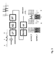
- FIG. 3 An embodiment of a receiver is shown in Fig. 3 .
- Signals are received in an analog front end which may comprise a lowpass filter LPF, an automatic gain control amplifier AGC and a high pass filter HPF.
- the low pass filter LPF is adapted to cut off all the noise above the signal frequency.
- the automatic gain control AGC tries to normalize the level of the signal to useful values.
- a preamble may be added in front of the first symbol, possibly in front of every symbol.
- the high pass filter HPF further cuts off all noise below the signal frequency. Since DC levels are blocked too, the received waveforms change to impulses. Note that LPF and HPF can have a gain above 1, and the AGC can also be put after the filters.
- This analog front end is followed by a deconvolutor denoted deconv which uses a single impulse response of the LPF-AGC-HPF combination to restore the signal to a more ideal representation of dirac pulses corresponding to the edges of the original signal.
- the correlator denoted corr is adapted to calculate the cross-correlation between the signal and the unit-pulse equivalent of symbol_0 and symbol_1. Whenever the correlation exceeds a threshold, the correlator decides it has recognized the symbol in the signal. This way, the original bitstream is recovered.
- the symbol recognition part comprising the deconvolutor and the correlator can be implemented on a processor e.g. a DFT coprocessor).
- a processor e.g. a DFT coprocessor
- the stability of the receiver clock is only needed during the symbol duration, which is relatively simple to realize.
- An example of such a transmitter/receiver combination via a capacitively coupled path can e.g. be a transmitter in a shoe, capacitively coupled to the floor at one side and the human body at the other side; and a receiver connected to a door handle at one side, and the same floor at the other side It is obvious that the act of a human hand touching the door handle would establish a capacitive path between transmitter and receiver, with the floor used as a signal return path.
- the path is only available when capacitive contact is established. Depending on the dimensioning of the electrodes, being Cbr en Cbt in Fig 1 , used, this could mean a contact distance from less than a mm to a few cm.
- This system has a very good selectivity: the path is only available when transmitter and receiver are coupled by a series of objects, such as a human body as mentioned in the previous example, that touch each other. Using unique codes on different transmitters, it is easy to detect which transmitter has touched the receiver.
- the transmitter - receiver combination can also be used in several modes: in a first mode the bitstream transmitted can be a simple serial ID (comparable to RFID tags). In another one the bitstream transmitted could be a digital representation of a sensor value. This allows to e.g. read out the sensor value by simply touching the device. But, as already mentioned the transmitter - receiver pair could be used as a data network, for instance a mobile device carried by person A could transmit e.g. a VCARD datastructure. On simple handshake, the mobile device of the other person could receive the VCARD and application logic could conclude that person A just encountered person B.
- any element expressed as a means for performing a specified function is intended to encompass any way of performing that function.
- This may include, for example, a) a combination of electrical or mechanical elements which performs that function or b) software in any form, including, therefore, firmware, microcode or the like, combined with appropriate circuitry for executing that software to perform the function, as well as mechanical elements coupled to software controlled circuitry, if any.
Landscapes
- Engineering & Computer Science (AREA)
- Computer Networks & Wireless Communication (AREA)
- Signal Processing (AREA)
- Near-Field Transmission Systems (AREA)
- Mobile Radio Communication Systems (AREA)
Claims (6)
- Sender für die Kommunikation über einen kapazitiven Kanal eines körpernahen Netzwerks mit einem Empfänger, wobei der besagte Sender für die Übertragung von Basisbandsignalen über den besagten Kanal an den besagten Empfänger ausgelegt ist und weiterhin einen Symbol-Codierer umfasst, welcher dazu ausgelegt ist, zu übertragende Informationen mit Binärsymbolen, welche Autokorrelations- und Kreuzkorrelationseigenschaften aufweisen, zu codieren, wobei die besagten Symbole durch ihre 0/1- und 1/0-Flanken gekennzeichnet sind, um eine Symbolunterscheidung an einem Empfänger, welcher die von dem besagten Sender übertragenen codierten Informationen empfängt, zu ermöglichen, wobei der besagte Sender weiterhin eine Identifikationslogik umfasst, welche eine während der besagten Kommunikation mit einem Empfänger zu übertragende, mit dem besagten Sender assoziierte eindeutige Kennung ermöglicht.
- Sender nach Anspruch 1, weiterhin umfassend eine Logik zur Bereitstellung von Sensorinformationen als Teil der besagten zu übertragenden Informationen.
- Sender nach einem beliebigen der Ansprüche 1-2, weiterhin umfassend mindestens einen weiteren Symbol-Codierer zum Codieren von Zufallsinformationen mit Binärsymbolen ohne Autokorrelations- und Kreuzkorrelationseigenschaften, wodurch nach dem Zufallsprinzip codierte Daten für die Überlagerung mit den zu übertragenden codierten Informationen für Verwürfelungszwecke erzeugt werden.
- Empfänger für die Kommunikation über einen kapazitiven Kanal eines körpernahen Netzwerks nach einem beliebigen der Ansprüche 1-3, wobei der besagte Empfänger für den Empfang und das Unterscheiden von Basisbandsignalen über den besagten Kanal von dem besagten Sender ausgelegt ist.
- Empfänger nach Anspruch 4, weiterhin umfassend eine Signalwiederherstellungsschaltung und einen Symbol-Decodierer.
- System zur Bereitstellung eines kapazitiven Kommunikationsnetzwerks eines körpernahen Basisband-Netzwerks, wobei das besagte System eine Vielzahl von Sendern und Empfängern gemäß einem beliebigen der vorstehenden Ansprüche umfasst.
Priority Applications (1)
| Application Number | Priority Date | Filing Date | Title |
|---|---|---|---|
| EP20100305319 EP2375596B1 (de) | 2010-03-29 | 2010-03-29 | Kapazitiv gekoppeltes Kommunikationssystem |
Applications Claiming Priority (1)
| Application Number | Priority Date | Filing Date | Title |
|---|---|---|---|
| EP20100305319 EP2375596B1 (de) | 2010-03-29 | 2010-03-29 | Kapazitiv gekoppeltes Kommunikationssystem |
Publications (2)
| Publication Number | Publication Date |
|---|---|
| EP2375596A1 EP2375596A1 (de) | 2011-10-12 |
| EP2375596B1 true EP2375596B1 (de) | 2014-11-19 |
Family
ID=42543339
Family Applications (1)
| Application Number | Title | Priority Date | Filing Date |
|---|---|---|---|
| EP20100305319 Active EP2375596B1 (de) | 2010-03-29 | 2010-03-29 | Kapazitiv gekoppeltes Kommunikationssystem |
Country Status (1)
| Country | Link |
|---|---|
| EP (1) | EP2375596B1 (de) |
Families Citing this family (1)
| Publication number | Priority date | Publication date | Assignee | Title |
|---|---|---|---|---|
| US20160166207A1 (en) * | 2014-12-11 | 2016-06-16 | Maynard C. Falconer | Technologies for biofeedback electrode contact monitoring |
Family Cites Families (4)
| Publication number | Priority date | Publication date | Assignee | Title |
|---|---|---|---|---|
| US8155586B2 (en) * | 2003-01-25 | 2012-04-10 | Korea Institute Of Science And Technology | Method and system for data communication using a body |
| KR100937602B1 (ko) * | 2007-12-13 | 2010-01-20 | 한국전자통신연구원 | 인체 통신 시스템 및 그것의 통신 방법 |
| KR100953564B1 (ko) * | 2008-03-11 | 2010-04-21 | 한국전자통신연구원 | 주파수 선택적 기저대역을 사용하는 변복조 장치 및 이를이용한 송수신 장치 |
| KR100942706B1 (ko) * | 2008-08-22 | 2010-02-16 | 한국전자통신연구원 | 인체 통신을 이용한 무선 주파수 식별 시스템 |
-
2010
- 2010-03-29 EP EP20100305319 patent/EP2375596B1/de active Active
Also Published As
| Publication number | Publication date |
|---|---|
| EP2375596A1 (de) | 2011-10-12 |
Similar Documents
| Publication | Publication Date | Title |
|---|---|---|
| EP3408681B1 (de) | Rückstreuvorrichtungen mit beispielen für einzelseitenbandbetrieb | |
| US9425905B2 (en) | Receiver for body channel communication and a method of operating a receiver therefrom | |
| EP2976734B1 (de) | Sender/empfänger mit umgebungsrückstreuung sowie vorrichtungen, systeme und verfahren zur kommunikation mittels rückstreuung von hf-umgebungssignalen | |
| EP2241033B1 (de) | Elektrodendiversität für körpergekoppelte kommunikationssysteme | |
| KR102619688B1 (ko) | 센서 컨트롤러, 위치 지시기, 및 위치 검출 시스템 | |
| US8467431B2 (en) | Human body communication system and communication method thereof | |
| Chi et al. | Concurrent cross-technology communication among heterogeneous IoT devices | |
| US9868068B2 (en) | Interactive amusement system, interactive wearing system and data transmission circuit for biological contact | |
| WO2015123306A1 (en) | Apparatuses, systems, and methods for communicating using mimo and spread spectrum coding in backscatter of ambient signals | |
| JP6129726B2 (ja) | 携帯端末 | |
| EP2375596B1 (de) | Kapazitiv gekoppeltes Kommunikationssystem | |
| KR20160013865A (ko) | 통신 장치, 통신 시스템, 및 통신 방법 | |
| JP6033427B2 (ja) | 複数のメッセージシンボルの無線伝送のための方法、システム、および、システムのための受信器 | |
| CN105162569A (zh) | 一种异步双工零射频无线通信系统 | |
| JP2008533755A (ja) | ワイヤレス通信ネットワークにおいてビットの系列をM−ary変調する方法 | |
| CN202870863U (zh) | 声波读写装置、移动终端及声波系统 | |
| RU94784U1 (ru) | Система связи через тело человека | |
| KR102727068B1 (ko) | 인체 통신 송신 장치 및 인체 통신 수신 장치 | |
| JP4653200B2 (ja) | 電極対および電界通信システム | |
| US7907669B2 (en) | Low-detectability communication between a transmitter and receiver | |
| Hancke | Modulating a noisy carrier signal for eavesdropping-resistant HF RFID | |
| JP2010268423A (ja) | 直交符号を使用する適応型周波数の選択的基底帯域通信方法 | |
| Wang et al. | Ultrasonic Multidimensional Index Modulation With Low-Complexity Maximum Likelihood Receiver for Intra-Body Communications | |
| Choi et al. | Novel transmission algorithm of UWB signals for WBAN applications | |
| KR20230140268A (ko) | 인체 통신 송신 장치 및 인체 통신 수신 장치 |
Legal Events
| Date | Code | Title | Description |
|---|---|---|---|
| PUAI | Public reference made under article 153(3) epc to a published international application that has entered the european phase |
Free format text: ORIGINAL CODE: 0009012 |
|
| AK | Designated contracting states |
Kind code of ref document: A1 Designated state(s): AT BE BG CH CY CZ DE DK EE ES FI FR GB GR HR HU IE IS IT LI LT LU LV MC MK MT NL NO PL PT RO SE SI SK SM TR |
|
| AX | Request for extension of the european patent |
Extension state: AL BA ME RS |
|
| RAP1 | Party data changed (applicant data changed or rights of an application transferred) |
Owner name: ALCATEL LUCENT |
|
| 17P | Request for examination filed |
Effective date: 20120412 |
|
| 111Z | Information provided on other rights and legal means of execution |
Free format text: AT BE BG CH CY CZ DE DK EE ES FI FR GB GR HR HU IE IS IT LI LT LU LV MC MK MT NL NO PL PT RO SE SI SK SM TR Effective date: 20130410 |
|
| GRAP | Despatch of communication of intention to grant a patent |
Free format text: ORIGINAL CODE: EPIDOSNIGR1 |
|
| INTG | Intention to grant announced |
Effective date: 20140314 |
|
| GRAP | Despatch of communication of intention to grant a patent |
Free format text: ORIGINAL CODE: EPIDOSNIGR1 |
|
| RIN1 | Information on inventor provided before grant (corrected) |
Inventor name: DOBBELAERE, PHILIPPE Inventor name: GODON, MARC Inventor name: FEKI, MOHAMED ALI Inventor name: ROELANDS, MARC |
|
| RAP1 | Party data changed (applicant data changed or rights of an application transferred) |
Owner name: ALCATEL LUCENT |
|
| INTG | Intention to grant announced |
Effective date: 20140731 |
|
| GRAS | Grant fee paid |
Free format text: ORIGINAL CODE: EPIDOSNIGR3 |
|
| GRAA | (expected) grant |
Free format text: ORIGINAL CODE: 0009210 |
|
| AK | Designated contracting states |
Kind code of ref document: B1 Designated state(s): AT BE BG CH CY CZ DE DK EE ES FI FR GB GR HR HU IE IS IT LI LT LU LV MC MK MT NL NO PL PT RO SE SI SK SM TR |
|
| D11X | Information provided on other rights and legal means of execution (deleted) | ||
| REG | Reference to a national code |
Ref country code: GB Ref legal event code: FG4D |
|
| REG | Reference to a national code |
Ref country code: CH Ref legal event code: EP |
|
| REG | Reference to a national code |
Ref country code: AT Ref legal event code: REF Ref document number: 697547 Country of ref document: AT Kind code of ref document: T Effective date: 20141215 |
|
| REG | Reference to a national code |
Ref country code: IE Ref legal event code: FG4D |
|
| REG | Reference to a national code |
Ref country code: DE Ref legal event code: R096 Ref document number: 602010020338 Country of ref document: DE Effective date: 20141231 |
|
| REG | Reference to a national code |
Ref country code: FR Ref legal event code: PLFP Year of fee payment: 6 |
|
| REG | Reference to a national code |
Ref country code: NL Ref legal event code: VDEP Effective date: 20141119 |
|
| REG | Reference to a national code |
Ref country code: AT Ref legal event code: MK05 Ref document number: 697547 Country of ref document: AT Kind code of ref document: T Effective date: 20141119 |
|
| REG | Reference to a national code |
Ref country code: LT Ref legal event code: MG4D |
|
| PG25 | Lapsed in a contracting state [announced via postgrant information from national office to epo] |
Ref country code: PT Free format text: LAPSE BECAUSE OF FAILURE TO SUBMIT A TRANSLATION OF THE DESCRIPTION OR TO PAY THE FEE WITHIN THE PRESCRIBED TIME-LIMIT Effective date: 20150319 Ref country code: NL Free format text: LAPSE BECAUSE OF FAILURE TO SUBMIT A TRANSLATION OF THE DESCRIPTION OR TO PAY THE FEE WITHIN THE PRESCRIBED TIME-LIMIT Effective date: 20141119 Ref country code: FI Free format text: LAPSE BECAUSE OF FAILURE TO SUBMIT A TRANSLATION OF THE DESCRIPTION OR TO PAY THE FEE WITHIN THE PRESCRIBED TIME-LIMIT Effective date: 20141119 Ref country code: IS Free format text: LAPSE BECAUSE OF FAILURE TO SUBMIT A TRANSLATION OF THE DESCRIPTION OR TO PAY THE FEE WITHIN THE PRESCRIBED TIME-LIMIT Effective date: 20150319 Ref country code: LT Free format text: LAPSE BECAUSE OF FAILURE TO SUBMIT A TRANSLATION OF THE DESCRIPTION OR TO PAY THE FEE WITHIN THE PRESCRIBED TIME-LIMIT Effective date: 20141119 Ref country code: ES Free format text: LAPSE BECAUSE OF FAILURE TO SUBMIT A TRANSLATION OF THE DESCRIPTION OR TO PAY THE FEE WITHIN THE PRESCRIBED TIME-LIMIT Effective date: 20141119 Ref country code: NO Free format text: LAPSE BECAUSE OF FAILURE TO SUBMIT A TRANSLATION OF THE DESCRIPTION OR TO PAY THE FEE WITHIN THE PRESCRIBED TIME-LIMIT Effective date: 20150219 |
|
| PG25 | Lapsed in a contracting state [announced via postgrant information from national office to epo] |
Ref country code: PL Free format text: LAPSE BECAUSE OF FAILURE TO SUBMIT A TRANSLATION OF THE DESCRIPTION OR TO PAY THE FEE WITHIN THE PRESCRIBED TIME-LIMIT Effective date: 20141119 Ref country code: HR Free format text: LAPSE BECAUSE OF FAILURE TO SUBMIT A TRANSLATION OF THE DESCRIPTION OR TO PAY THE FEE WITHIN THE PRESCRIBED TIME-LIMIT Effective date: 20141119 Ref country code: CY Free format text: LAPSE BECAUSE OF FAILURE TO SUBMIT A TRANSLATION OF THE DESCRIPTION OR TO PAY THE FEE WITHIN THE PRESCRIBED TIME-LIMIT Effective date: 20141119 Ref country code: AT Free format text: LAPSE BECAUSE OF FAILURE TO SUBMIT A TRANSLATION OF THE DESCRIPTION OR TO PAY THE FEE WITHIN THE PRESCRIBED TIME-LIMIT Effective date: 20141119 Ref country code: LV Free format text: LAPSE BECAUSE OF FAILURE TO SUBMIT A TRANSLATION OF THE DESCRIPTION OR TO PAY THE FEE WITHIN THE PRESCRIBED TIME-LIMIT Effective date: 20141119 Ref country code: SE Free format text: LAPSE BECAUSE OF FAILURE TO SUBMIT A TRANSLATION OF THE DESCRIPTION OR TO PAY THE FEE WITHIN THE PRESCRIBED TIME-LIMIT Effective date: 20141119 Ref country code: GR Free format text: LAPSE BECAUSE OF FAILURE TO SUBMIT A TRANSLATION OF THE DESCRIPTION OR TO PAY THE FEE WITHIN THE PRESCRIBED TIME-LIMIT Effective date: 20150220 |
|
| PG25 | Lapsed in a contracting state [announced via postgrant information from national office to epo] |
Ref country code: CZ Free format text: LAPSE BECAUSE OF FAILURE TO SUBMIT A TRANSLATION OF THE DESCRIPTION OR TO PAY THE FEE WITHIN THE PRESCRIBED TIME-LIMIT Effective date: 20141119 Ref country code: SK Free format text: LAPSE BECAUSE OF FAILURE TO SUBMIT A TRANSLATION OF THE DESCRIPTION OR TO PAY THE FEE WITHIN THE PRESCRIBED TIME-LIMIT Effective date: 20141119 Ref country code: DK Free format text: LAPSE BECAUSE OF FAILURE TO SUBMIT A TRANSLATION OF THE DESCRIPTION OR TO PAY THE FEE WITHIN THE PRESCRIBED TIME-LIMIT Effective date: 20141119 Ref country code: EE Free format text: LAPSE BECAUSE OF FAILURE TO SUBMIT A TRANSLATION OF THE DESCRIPTION OR TO PAY THE FEE WITHIN THE PRESCRIBED TIME-LIMIT Effective date: 20141119 Ref country code: RO Free format text: LAPSE BECAUSE OF FAILURE TO SUBMIT A TRANSLATION OF THE DESCRIPTION OR TO PAY THE FEE WITHIN THE PRESCRIBED TIME-LIMIT Effective date: 20141119 |
|
| REG | Reference to a national code |
Ref country code: DE Ref legal event code: R097 Ref document number: 602010020338 Country of ref document: DE |
|
| PLBE | No opposition filed within time limit |
Free format text: ORIGINAL CODE: 0009261 |
|
| STAA | Information on the status of an ep patent application or granted ep patent |
Free format text: STATUS: NO OPPOSITION FILED WITHIN TIME LIMIT |
|
| 26N | No opposition filed |
Effective date: 20150820 |
|
| PG25 | Lapsed in a contracting state [announced via postgrant information from national office to epo] |
Ref country code: LU Free format text: LAPSE BECAUSE OF FAILURE TO SUBMIT A TRANSLATION OF THE DESCRIPTION OR TO PAY THE FEE WITHIN THE PRESCRIBED TIME-LIMIT Effective date: 20150329 Ref country code: MC Free format text: LAPSE BECAUSE OF FAILURE TO SUBMIT A TRANSLATION OF THE DESCRIPTION OR TO PAY THE FEE WITHIN THE PRESCRIBED TIME-LIMIT Effective date: 20141119 |
|
| REG | Reference to a national code |
Ref country code: CH Ref legal event code: PL |
|
| PG25 | Lapsed in a contracting state [announced via postgrant information from national office to epo] |
Ref country code: IT Free format text: LAPSE BECAUSE OF FAILURE TO SUBMIT A TRANSLATION OF THE DESCRIPTION OR TO PAY THE FEE WITHIN THE PRESCRIBED TIME-LIMIT Effective date: 20141119 |
|
| REG | Reference to a national code |
Ref country code: IE Ref legal event code: MM4A |
|
| PG25 | Lapsed in a contracting state [announced via postgrant information from national office to epo] |
Ref country code: CH Free format text: LAPSE BECAUSE OF NON-PAYMENT OF DUE FEES Effective date: 20150331 Ref country code: LI Free format text: LAPSE BECAUSE OF NON-PAYMENT OF DUE FEES Effective date: 20150331 Ref country code: IE Free format text: LAPSE BECAUSE OF NON-PAYMENT OF DUE FEES Effective date: 20150329 |
|
| PG25 | Lapsed in a contracting state [announced via postgrant information from national office to epo] |
Ref country code: SI Free format text: LAPSE BECAUSE OF FAILURE TO SUBMIT A TRANSLATION OF THE DESCRIPTION OR TO PAY THE FEE WITHIN THE PRESCRIBED TIME-LIMIT Effective date: 20141119 |
|
| REG | Reference to a national code |
Ref country code: FR Ref legal event code: PLFP Year of fee payment: 7 |
|
| PG25 | Lapsed in a contracting state [announced via postgrant information from national office to epo] |
Ref country code: MT Free format text: LAPSE BECAUSE OF FAILURE TO SUBMIT A TRANSLATION OF THE DESCRIPTION OR TO PAY THE FEE WITHIN THE PRESCRIBED TIME-LIMIT Effective date: 20141119 |
|
| REG | Reference to a national code |
Ref country code: FR Ref legal event code: PLFP Year of fee payment: 8 |
|
| PG25 | Lapsed in a contracting state [announced via postgrant information from national office to epo] |
Ref country code: BG Free format text: LAPSE BECAUSE OF FAILURE TO SUBMIT A TRANSLATION OF THE DESCRIPTION OR TO PAY THE FEE WITHIN THE PRESCRIBED TIME-LIMIT Effective date: 20141119 Ref country code: SM Free format text: LAPSE BECAUSE OF FAILURE TO SUBMIT A TRANSLATION OF THE DESCRIPTION OR TO PAY THE FEE WITHIN THE PRESCRIBED TIME-LIMIT Effective date: 20141119 Ref country code: HU Free format text: LAPSE BECAUSE OF FAILURE TO SUBMIT A TRANSLATION OF THE DESCRIPTION OR TO PAY THE FEE WITHIN THE PRESCRIBED TIME-LIMIT; INVALID AB INITIO Effective date: 20100329 |
|
| PG25 | Lapsed in a contracting state [announced via postgrant information from national office to epo] |
Ref country code: TR Free format text: LAPSE BECAUSE OF FAILURE TO SUBMIT A TRANSLATION OF THE DESCRIPTION OR TO PAY THE FEE WITHIN THE PRESCRIBED TIME-LIMIT Effective date: 20141119 |
|
| PG25 | Lapsed in a contracting state [announced via postgrant information from national office to epo] |
Ref country code: BE Free format text: LAPSE BECAUSE OF FAILURE TO SUBMIT A TRANSLATION OF THE DESCRIPTION OR TO PAY THE FEE WITHIN THE PRESCRIBED TIME-LIMIT Effective date: 20141119 |
|
| REG | Reference to a national code |
Ref country code: FR Ref legal event code: PLFP Year of fee payment: 9 |
|
| PG25 | Lapsed in a contracting state [announced via postgrant information from national office to epo] |
Ref country code: MK Free format text: LAPSE BECAUSE OF FAILURE TO SUBMIT A TRANSLATION OF THE DESCRIPTION OR TO PAY THE FEE WITHIN THE PRESCRIBED TIME-LIMIT Effective date: 20141119 |
|
| PGFP | Annual fee paid to national office [announced via postgrant information from national office to epo] |
Ref country code: DE Payment date: 20250204 Year of fee payment: 16 |
|
| PGFP | Annual fee paid to national office [announced via postgrant information from national office to epo] |
Ref country code: FR Payment date: 20250210 Year of fee payment: 16 |
|
| PGFP | Annual fee paid to national office [announced via postgrant information from national office to epo] |
Ref country code: GB Payment date: 20250206 Year of fee payment: 16 |