EP2375530A1 - Onboard floating drilling installation and method for operating an onboard floating drilling installation - Google Patents
Onboard floating drilling installation and method for operating an onboard floating drilling installation Download PDFInfo
- Publication number
- EP2375530A1 EP2375530A1 EP10159486A EP10159486A EP2375530A1 EP 2375530 A1 EP2375530 A1 EP 2375530A1 EP 10159486 A EP10159486 A EP 10159486A EP 10159486 A EP10159486 A EP 10159486A EP 2375530 A1 EP2375530 A1 EP 2375530A1
- Authority
- EP
- European Patent Office
- Prior art keywords
- floating drilling
- thrusters
- onboard floating
- drilling installation
- draw works
- Prior art date
- Legal status (The legal status is an assumption and is not a legal conclusion. Google has not performed a legal analysis and makes no representation as to the accuracy of the status listed.)
- Withdrawn
Links
Images
Classifications
-
- B—PERFORMING OPERATIONS; TRANSPORTING
- B63—SHIPS OR OTHER WATERBORNE VESSELS; RELATED EQUIPMENT
- B63H—MARINE PROPULSION OR STEERING
- B63H25/00—Steering; Slowing-down otherwise than by use of propulsive elements; Dynamic anchoring, i.e. positioning vessels by means of main or auxiliary propulsive elements
- B63H25/42—Steering or dynamic anchoring by propulsive elements; Steering or dynamic anchoring by propellers used therefor only; Steering or dynamic anchoring by rudders carrying propellers
-
- B—PERFORMING OPERATIONS; TRANSPORTING
- B63—SHIPS OR OTHER WATERBORNE VESSELS; RELATED EQUIPMENT
- B63J—AUXILIARIES ON VESSELS
- B63J3/00—Driving of auxiliaries
- B63J3/02—Driving of auxiliaries from propulsion power plant
-
- E—FIXED CONSTRUCTIONS
- E21—EARTH DRILLING; MINING
- E21B—EARTH DRILLING, e.g. DEEP DRILLING; OBTAINING OIL, GAS, WATER, SOLUBLE OR MELTABLE MATERIALS OR A SLURRY OF MINERALS FROM WELLS
- E21B41/00—Equipment or details not covered by groups E21B15/00 - E21B40/00
- E21B41/0007—Equipment or details not covered by groups E21B15/00 - E21B40/00 for underwater installations
-
- H—ELECTRICITY
- H02—GENERATION; CONVERSION OR DISTRIBUTION OF ELECTRIC POWER
- H02J—CIRCUIT ARRANGEMENTS OR SYSTEMS FOR SUPPLYING OR DISTRIBUTING ELECTRIC POWER; SYSTEMS FOR STORING ELECTRIC ENERGY
- H02J3/00—Circuit arrangements for ac mains or ac distribution networks
- H02J3/38—Arrangements for parallely feeding a single network by two or more generators, converters or transformers
-
- B—PERFORMING OPERATIONS; TRANSPORTING
- B63—SHIPS OR OTHER WATERBORNE VESSELS; RELATED EQUIPMENT
- B63H—MARINE PROPULSION OR STEERING
- B63H21/00—Use of propulsion power plant or units on vessels
- B63H21/12—Use of propulsion power plant or units on vessels the vessels being motor-driven
- B63H21/17—Use of propulsion power plant or units on vessels the vessels being motor-driven by electric motor
-
- B—PERFORMING OPERATIONS; TRANSPORTING
- B63—SHIPS OR OTHER WATERBORNE VESSELS; RELATED EQUIPMENT
- B63J—AUXILIARIES ON VESSELS
- B63J3/00—Driving of auxiliaries
- B63J2003/001—Driving of auxiliaries characterised by type of power supply, or power transmission, e.g. by using electric power or steam
- B63J2003/002—Driving of auxiliaries characterised by type of power supply, or power transmission, e.g. by using electric power or steam by using electric power
-
- B—PERFORMING OPERATIONS; TRANSPORTING
- B63—SHIPS OR OTHER WATERBORNE VESSELS; RELATED EQUIPMENT
- B63J—AUXILIARIES ON VESSELS
- B63J3/00—Driving of auxiliaries
- B63J3/04—Driving of auxiliaries from power plant other than propulsion power plant
-
- H—ELECTRICITY
- H02—GENERATION; CONVERSION OR DISTRIBUTION OF ELECTRIC POWER
- H02J—CIRCUIT ARRANGEMENTS OR SYSTEMS FOR SUPPLYING OR DISTRIBUTING ELECTRIC POWER; SYSTEMS FOR STORING ELECTRIC ENERGY
- H02J2310/00—The network for supplying or distributing electric power characterised by its spatial reach or by the load
- H02J2310/40—The network being an on-board power network, i.e. within a vehicle
- H02J2310/42—The network being an on-board power network, i.e. within a vehicle for ships or vessels
Definitions
- the invention relates to a method for operating an onboard floating drilling installation, comprising a draw-works for reeling out and reeling in a drilling line, whereby the draw works comprises at least one drilling drive, comprising several thrusters for dynamic positioning the onboard floating drilling installation and comprising at least one generator to operate the thrusters and the draw works.
- the invention relates further to an onboard floating drilling installation, comprising a draw-works for reeling out and reeling in a drilling line, whereby the draw works comprises at least one drilling drive, comprising several thrusters for dynamic positioning the onboard floating drilling installation and comprising at least one generator to operate the thrusters and the draw works.
- Onboard floating drilling installations like drillships or semisubmersible drilling rigs, are maritime vessels which have been fitted with drilling equipment. Onboard floating drilling installations are normally used for exploratory drilling of new oil or gas wells in deep water but can also be used for scientific drilling. They are able to drill in water depths up to 3500-4000 m. Most of the onboard floating drilling installations are outfitted with a dynamic positioning system to maintain position over the well.
- a dynamic positioning system is a computer controlled system to automatically maintain an onboard floating drilling installation's position and heading by using own propellers and thrusters.
- Position reference sensors combined with motion sensors, wind sensors and gyro compasses, provide information to the computer of the dynamic positioning system pertaining to the onboard floating drilling installation's position and the magnitude and direction of environmental forces affecting its position.
- the computer program working in the dynamic positioning system contains a mathematical model of the onboard floating drilling installation that includes information pertaining to the wind and current drag of the onboard floating drilling installation and the location of the thrusters of the onboard floating drilling installation. This knowledge, combined with the sensor information, allows the computer to calculate the required steering angle and thruster output for each thruster. This allows operations at sea where mooring or anchoring is not feasible due to deep water, congestions of pipelines or drilling equipment on the sea bottom or other problems.
- Dynamic positioning may either be absolute in that the position of the onboard floating drilling installation is locked to a fixed point over the sea bottom, or relative to a moving object like a ship or another underwater vehicle.
- the onboard floating drilling installation can also be positioned at an advantageous angle towards wind, waves and flow of water.
- Such onboard floating drilling installations comprises draw works for reeling out and reeling in a drilling line, whereby the draw works comprises at least one drilling drive.
- onboard floating drilling installations comprise several propellers or thrusters for dynamic positioning the onboard floating drilling installation.
- onboard floating drilling installations comprise one or more generators for producing electric current to operate the thrusters and the draw works.
- Onboard floating oil drilling installations such as semisubmersible drilling rigs or drillships trend towards electrically operated draw-works with active heave compensation. This is used in order to keep a constant pressure on the drill bit during the drilling. This generates a need for a big oscillating load at the frequency of the sea waves.
- the object to be solved is to provide a method for operating an onboard floating drilling installation and an onboard floating drilling installation, which enable that the power pull from the generators of the onboard floating drilling installation is kept as stable as possible during the operation of the thrusters and the draw-works and thus enable a low fuel consumption of the onboard floating drilling installation.
- the problem is solved by a method for operating an onboard floating drilling installation, comprising a draw-works for reeling out and reeling in a drilling line, whereby the draw works comprises at least one drilling drive, comprising several thrusters for dynamic positioning the onboard floating drilling installation and comprising at least one generator to operate the thrusters and the draw works, whereby the method is characterized by following steps:
- Information about the power consumption of the draw works have to be collected, This can be done over a predefined period of time or over the whole time.
- the power oscillation and the magnitude of the power consumption of the draw works are determined out of the measuring results.
- a power oscillation signal based on the results of the measurement of the power consumption of the draw works is generated, whereby the power oscillation signal represents the power oscillation and the magnitude of the power consumption of the draw works over the certain period of time.
- an anti-oscillation signal for the thrusters has be generated and distributed to the individual thrusters.
- an anti-oscillation signal which represents a power oscillation with an opposite phase characteristics to the power oscillation signal of the draw works is generated in the next step.
- This anti-oscillation signal is then distributed to the thrusters and the power consumption of the thrusters is adjusted to the anti-oscillation signal.
- the anti-oscillation signal causes the thrusters to vary their load consumption in opposite phase and similar magnitude as the draw works. In this way the average thrust is not affected.
- the load variation on the thrusters does not have any effect on the ability to keep the onboard floating drilling installation in a steady position.
- the thrusters used for dynamic positioning and the drilling drives of the draw works are interconnected in such a way that the power pull from the generators is kept as stable as possible. This is been done by generating a signal from the draw works representing the power oscillation. This power oscillation signal is superimposed on the control signal for the thrusters adjusting their power consumption to the opposite phase as the draw works and thus generating a constant power delivered from the generators.
- the anti-oscillation signal to the thrusters is arranged in such a way that it complies with the regulations for the relevant dynamic positioning class (DP class).
- the main advantages of this method for operating an onboard floating drilling installation are, that the generators have a much more constant load, which results in a reduced fuel consumption, and due to a lower peak power and stable load the onboard floating drilling installation can be operated with a lower number of running generators, reducing the operational cost even more.
- the method is characterized in that a control unit, in particular a dynamic positioning control unit, of the onboard floating drilling installation carries out at least the steps b), c) and d) of the before described method.
- the power consumption of the draw works can be measured over a defined period of time by measuring means.
- the determination of the power oscillation and the magnitude of the power consumption of the draw works over the defined period of time can be done by the control unit, as well.
- the power oscillation signal is generated by the control unit.
- the control unit can generate an anti-oscillation signal which represents the same or a similar magnitude of the load consumption and a power oscillation with an opposite phase characteristics to the power oscillation signal of the draw works.
- the anti-oscillation signal is distributed by the control unit to the thrusters.
- the thrusters adjusted their power consumption according to the anti-oscillation signal.
- the thrusters pull their power from the at least one generator of the onboard floating drilling installation at that time when the draw works do not pull power from the at least one generator.
- the power pull from the one or more generators can be kept very stable or constant over the time, respectively.
- a method for operating an onboard floating drilling installation whereby the at least one generator produces electric current and feeds the electric current into the grid of the onboard floating drilling installation to operate the draw works and the thrusters.
- the at least one generator feeds electric current into the onboard grid, which distributes the electric current to the draw works, in particular the drilling drive or drilling bits, and to the thrusters.
- a method is preferred, which is characterized in that braking energy of sea waves is converted into electric energy and this electric energy is fed into the grid of the onboard floating drilling installation to operate the draw works and/or the thrusters.
- the braking energy of sea waves can be used to operate the draw works and/or the thrusters.
- the at least one generator can be disburdened.
- the fuel consumption can be reduced by reuse of the braking energy by the thrusters.
- the braking energy of the sea waves can be converted into electric energy by converter means. It is preferred, that the braking energy of the sea waves is converted into electric energy by at least one four-quadrant converter.
- the draw works may be equipped with at least one four quadrant converter, enabling a refeeding of the braking energy to the grid of the onboard floating drilling installation, or alternatively with braking resistors and one way rectifiers, enabling only compensation of the oscillation of the active power. Therefore, a method is advantageously, whereby at least one braking resistor and at least one way rectifier compensate the oscillation of the power needed by the draw works and/or the thrusters.
- the draw works and the thrusters may also be connected to one or more DC buses. Furthermore, this may combined and the operation may be made dependent on the overall load situation on board.
- an onboard floating drilling installation comprising draw-works for reeling out and reeling in a drilling line
- the draw works comprises at least one drilling drive, comprising several thrusters for dynamic positioning the onboard floating drilling installation and comprising at least one generator to operate the thrusters and the draw works
- the onboard floating drilling installation comprises a measuring unit for measuring the power consumption of the draw works over at least a certain period of time, means for determination of the power oscillation and the magnitude of the power consumption of the draw works over the at least certain period of time, a first generation unit for generating a power oscillation signal based on the results of the measurement of the power consumption of the draw works, whereby the power oscillation signal represents the power oscillation and the magnitude of the power consumption
- the generators of such an onboard floating drilling installation operate with a constant load.
- the less variation of load reduces the fuel consumption of the generators and therefore the fuel consumption of the onboard floating drilling installation. Due to a lower peak power and stable load the onboard floating drilling installation can be operated with a lower number of running generators, reducing the operational cost even more.
- Information about the power consumption of the draw works can to be collected. This can be done over a predefined period of time or over the whole time by the measuring unit of the onboard floating drilling installation.
- the measuring unit comprises at least one sensor for measuring the power consumption of the draw works. After measuring the power consumption of the draw works the power oscillation and the magnitude of the power consumption of the draw works are determined out of the measuring results by determination means.
- a first generation unit generates a power oscillation signal based on the results of the measurement of the power consumption of the draw works, whereby the power oscillation signal represents the determined power oscillation and the magnitude of the power consumption of the draw works over at least the certain period of time.
- a second generation unit generates an anti-oscillation signal which represents a power oscillation with an opposite phase characteristics to the power oscillation signal of the draw works.
- This anti-oscillation signal is distributed to the thrusters by a distributing unit.
- an adjusting device adjusts the power consumption of the thrusters according to the anti-oscillation signal.
- the anti-oscillation signal causes the thrusters to vary their load consumption in opposite phase and similar magnitude as the draw works. In this way the average thrust is not affected.
- the load variation on the thrusters does not have any effect on the ability to keep the onboard floating drilling installation in a steady position.
- an onboard floating drilling installation whereby the measuring unit, the first and the second generation unit and the distributing unit are part of a control unit of the onboard floating drilling installation.
- the control unit can be a dynamic positioning control unit.
- the control unit enables a control of the power pull from the generator(s) of the onboard floating drilling installation.
- the control unit can further comprise the measuring unit and/or the adjusting device.
- the at least one generator produces electric current and feeds the electric current into the grid of the onboard floating drilling installation to operate the draw works and the thrusters.
- the at least one generator comprises means for feeding electric current into the onboard grid to distribute the electric current to the draw works, in particular the drilling drive or drilling bits, and to the thrusters.
- an onboard floating drilling installation comprising a converter unit to convert the braking energy of sea waves into electric energy and a feeding unit to feed this electric energy into the grid of the onboard floating drilling installation to operate the draw works and the thrusters.
- the braking energy of sea waves can be used to operate the draw works and/or the thrusters, as well.
- the fuel consumption can be reduced by reuse of the braking energy by the thrusters.
- the braking energy of the sea waves can be converted into electric energy by a converter unit.
- the converter unit comprises advantageously at least one four-quadrant converter for converting the braking energy of the sea into electric energy.
- the draw works may be equipped with at least one four quadrant converter, enabling a refeeding of the braking energy to the grid of the onboard floating drilling installation, or alternatively with braking resistors and one way rectifiers, enabling only compensation of the oscillation of the active power. Therefore, according to a further advantageous development of the invention an onboard floating drilling installation is provided, whereby the onboard floating drilling installation comprises at least one braking resistor and at least one way rectifier for compensating the oscillation of the power needed by the draw works and/or the thrusters.
- an onboard floating drilling installation whereby the draw works and the thrusters of the onboard floating drilling installation are connected to at least one DC bus.
- the onboard floating drilling installation can be, for example, a vessel, like a semisubmersible drilling rig or a drillship.
- the onboard floating drilling installation comprises a large-diameter steel spool, brakes, a power source like at least one generator and assorted auxiliary devices.
- the primary function of the draw works is to reel out and reel in the drilling line, which is a large diameter wire rope, in a controlled fashion.
- the drilling line is reeled over a crown block and a traveling block to gain mechanical advantage in a "block and tackle” or “pulley” fashion.
- This reeling out and reeling in of the drilling line causes the traveling block, and whatever may be hanging underneath it, to be lowered into or raised out of the wellbore.
- the reeling out of the drilling line is powered by gravity and the reeling in advantageously by an electric motor or a diesel engine.
- the drilling drive and the drill bit are use to drill a wellbore.
- the onboard floating drilling installation can comprise component like a mud tank, a derrick or mast, mud pumps, the draw works, a rotary table or topdrive, the drilling line or string, the power generation equipment and auxiliary equipment.
- the hoisting mechanism on the onboard floating drilling installation is a large winch that spools off or takes in the drilling line and thus raises or lowers the drill stem and bit.
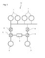
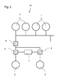
- Fig. 1 and Fig. 2 illustrate two different embodiments of power supply system 10 of onboard floating drilling installations, like semisubmersible drilling rigs or drillships.
- the draw works 2 and the thrusters 3 pull power from the generators 1.
- a control unit is interconnected between the generators 1 and the draw works 2 and the thrusters 3.
- the thrusters 3 used for dynamic positioning and drilling drives of the draw works 2 are interconnected in such a way that the power pull from the generators 2 is kept as stable as possible. This is been done by generating a signal from the draw works 2 representing the power oscillation. This power oscillation signal is superimposed on the control signal for the thrusters 3 adjusting their power consumption to the opposite phase as the draw works 2 and thus generating a constant power delivered from the generators 1.
- the DC bus is used for the exchange of the oscillating energy.
- the one way rectifiers 6 and a control unit 4 are interconnected between the generators 1 and the draw works 2 and the thrusters 3.
- the one way rectifiers 6, the control unit 4 and braking resistors enable a compensation of the oscillation of the active power.
Priority Applications (16)
| Application Number | Priority Date | Filing Date | Title |
|---|---|---|---|
| EP10159486A EP2375530A1 (en) | 2010-04-09 | 2010-04-09 | Onboard floating drilling installation and method for operating an onboard floating drilling installation |
| US13/639,537 US8951078B2 (en) | 2010-04-09 | 2011-03-18 | Onboard floating drilling installation and method for operating an onboard floating drilling installation |
| BR112012025807-9A BR112012025807B1 (pt) | 2010-04-09 | 2011-03-18 | método para operar instalação de perfuração flutuante embarcada e instalação de perfuração flutuante embarcada |
| KR1020127029520A KR101912594B1 (ko) | 2010-04-09 | 2011-03-18 | 온보드 부유 시추 설비와 온보드 부유 시추 설비의 작동 방법 |
| DK11708879.9T DK2539986T3 (en) | 2010-04-09 | 2011-03-18 | Liquid, built-in the drilling device and method for driving a liquid, built drilling assembly |
| PCT/EP2011/054114 WO2011124459A2 (en) | 2010-04-09 | 2011-03-18 | Onboard floating drilling installation and method for operating an onboard floating drilling installation |
| EP11708879.9A EP2539986B1 (en) | 2010-04-09 | 2011-03-18 | Onboard floating drilling installation and method for operating an onboard floating drilling installation |
| CN201180028237.5A CN102918736B (zh) | 2010-04-09 | 2011-03-18 | 船载浮动钻井设施和用于操作船载浮动钻井设施的方法 |
| KR1020127029466A KR20130093492A (ko) | 2010-04-09 | 2011-03-23 | 마린 드릴링 베셀을 위한 전력 공급 시스템 |
| CN201180018250.2A CN102812611B (zh) | 2010-04-09 | 2011-03-23 | 用于海洋钻探船舶的电源系统及其控制方法 |
| PCT/EP2011/054402 WO2011124470A2 (en) | 2010-04-09 | 2011-03-23 | Power supply system for marine drilling vessel |
| KR1020177030206A KR20170120203A (ko) | 2010-04-09 | 2011-03-23 | 마린 드릴링 베셀을 위한 전력 공급 시스템 |
| DK11712210.1T DK2569844T3 (en) | 2010-04-09 | 2011-03-23 | ENERGY SUPPLY SYSTEM FOR MARITIME DRILLING VESSELS |
| EP11712210.1A EP2569844B1 (en) | 2010-04-09 | 2011-03-23 | Power supply system for marine drilling vessel |
| BR112012025823A BR112012025823B1 (pt) | 2010-04-09 | 2011-03-23 | sistema de abastecimento de força para navio-sonda marinho e método de controle de um sistema de abastecimento de força de um navio-sonda marinho |
| US13/639,470 US8961247B2 (en) | 2010-04-09 | 2011-03-23 | Power supply system for marine drilling vessel |
Applications Claiming Priority (1)
| Application Number | Priority Date | Filing Date | Title |
|---|---|---|---|
| EP10159486A EP2375530A1 (en) | 2010-04-09 | 2010-04-09 | Onboard floating drilling installation and method for operating an onboard floating drilling installation |
Publications (1)
| Publication Number | Publication Date |
|---|---|
| EP2375530A1 true EP2375530A1 (en) | 2011-10-12 |
Family
ID=42830594
Family Applications (2)
| Application Number | Title | Priority Date | Filing Date |
|---|---|---|---|
| EP10159486A Withdrawn EP2375530A1 (en) | 2010-04-09 | 2010-04-09 | Onboard floating drilling installation and method for operating an onboard floating drilling installation |
| EP11708879.9A Not-in-force EP2539986B1 (en) | 2010-04-09 | 2011-03-18 | Onboard floating drilling installation and method for operating an onboard floating drilling installation |
Family Applications After (1)
| Application Number | Title | Priority Date | Filing Date |
|---|---|---|---|
| EP11708879.9A Not-in-force EP2539986B1 (en) | 2010-04-09 | 2011-03-18 | Onboard floating drilling installation and method for operating an onboard floating drilling installation |
Country Status (7)
| Country | Link |
|---|---|
| US (1) | US8951078B2 (zh) |
| EP (2) | EP2375530A1 (zh) |
| KR (1) | KR101912594B1 (zh) |
| CN (1) | CN102918736B (zh) |
| BR (1) | BR112012025807B1 (zh) |
| DK (1) | DK2539986T3 (zh) |
| WO (1) | WO2011124459A2 (zh) |
Families Citing this family (4)
| Publication number | Priority date | Publication date | Assignee | Title |
|---|---|---|---|---|
| EP3196116A4 (en) * | 2014-08-22 | 2018-05-02 | Daewoo Shipbuilding & Marine Engineering Co., Ltd. | Apparatus and method for controlling and monitoring auxiliary apparatus of drilling equipment in drill ship |
| CN104635699B (zh) * | 2015-01-15 | 2017-05-31 | 上海中远船务工程有限公司 | Dp3超深水钻井设备配电系统 |
| US20180257752A1 (en) * | 2017-03-08 | 2018-09-13 | Zentech, Inc. | Dynamically positioned liquid mud plant vessel |
| US20200295640A1 (en) * | 2019-03-15 | 2020-09-17 | Baker Hughes Oilfield Operations Llc | Power generation with speed dependent magnetic field control |
Citations (5)
| Publication number | Priority date | Publication date | Assignee | Title |
|---|---|---|---|---|
| US2966221A (en) * | 1956-11-23 | 1960-12-27 | Union Oil Co | Well drilling process and apparatus |
| US4167147A (en) * | 1976-01-19 | 1979-09-11 | Seatek Corp. | Method and apparatus for stabilizing a floating structure |
| US20090195074A1 (en) * | 2008-01-31 | 2009-08-06 | Buiel Edward R | Power supply and storage device for improving drilling rig operating efficiency |
| US20100009578A1 (en) * | 2008-07-14 | 2010-01-14 | General Electric Company | System and method for dynamic energy recovery in marine propulsion |
| WO2010092113A1 (en) * | 2009-02-13 | 2010-08-19 | Wartsila Norway As | Power supply system |
Family Cites Families (21)
| Publication number | Priority date | Publication date | Assignee | Title |
|---|---|---|---|---|
| US3552343A (en) * | 1969-01-10 | 1971-01-05 | Pan American Petroleum Corp | Drilling ship mooring system |
| US3653636A (en) * | 1970-02-09 | 1972-04-04 | Exxon Production Research Co | Wave motion compensation system for suspending well equipment from a floating vessel |
| US3804183A (en) | 1972-05-01 | 1974-04-16 | Rucker Co | Drill string compensator |
| IT1009574B (it) * | 1974-01-21 | 1976-12-20 | Saipem Spa | Metodo perfezionato per il posizio namento di un natante in particola re di una nave di perforazione e relativi dispositvi |
| US4205379A (en) * | 1977-05-16 | 1980-05-27 | TRW Inc., Systems & Energy | Position determining and dynamic positioning method and system for floating marine well drill platforms and the like |
| US4232903A (en) | 1978-12-28 | 1980-11-11 | Lockheed Missiles & Space Co., Inc. | Ocean mining system and process |
| US4516882A (en) | 1982-06-11 | 1985-05-14 | Fluor Subsea Services, Inc. | Method and apparatus for conversion of semi-submersible platform to tension leg platform for conducting offshore well operations |
| US5894895A (en) * | 1996-11-25 | 1999-04-20 | Welsh; Walter Thomas | Heave compensator for drill ships |
| GB9807070D0 (en) | 1998-04-01 | 1998-06-03 | Seabed Impeller Levelling And | Dredging apparatus |
| PT1187760E (pt) * | 1999-06-24 | 2004-09-30 | Siemens Ag | Sistema de propulsao e pilotagem para navios |
| US20020035957A1 (en) * | 2000-02-04 | 2002-03-28 | Fischer Ferdinand J. | Thruster apparatus and method for reducing fluid-induced motions of and stresses within an offshore platform |
| US7958715B2 (en) | 2003-03-13 | 2011-06-14 | National Oilwell Varco, L.P. | Chain with identification apparatus |
| US6932326B1 (en) | 2003-06-13 | 2005-08-23 | Richard L. Krabbendam | Method for lifting and transporting a heavy load using a fly-jib |
| JP4440880B2 (ja) * | 2003-06-26 | 2010-03-24 | 東芝三菱電機産業システム株式会社 | 電動機駆動システム |
| US9784041B2 (en) | 2004-04-15 | 2017-10-10 | National Oilwell Varco L.P. | Drilling rig riser identification apparatus |
| NO321428B1 (no) | 2004-06-04 | 2006-05-08 | Wartsila Automation Norway As | Kraftforsyningssystem |
| NO320841B1 (no) | 2004-06-08 | 2006-01-30 | Marine Cybernetics As | Fremgangsmate for testing av et kombinert dynamisk posisjonerings- og kraftreguleringssystem |
| US8513911B2 (en) | 2007-05-11 | 2013-08-20 | Converteam Technology Ltd. | Power converters |
| GB2449119B (en) | 2007-05-11 | 2012-02-29 | Converteam Technology Ltd | Power converters |
| US8858277B2 (en) | 2008-07-14 | 2014-10-14 | General Electric Company | System and method for dynamic energy recovery in marine propulsion |
| KR20170120203A (ko) | 2010-04-09 | 2017-10-30 | 지멘스 악티엔게젤샤프트 | 마린 드릴링 베셀을 위한 전력 공급 시스템 |
-
2010
- 2010-04-09 EP EP10159486A patent/EP2375530A1/en not_active Withdrawn
-
2011
- 2011-03-18 KR KR1020127029520A patent/KR101912594B1/ko active IP Right Grant
- 2011-03-18 CN CN201180028237.5A patent/CN102918736B/zh not_active Expired - Fee Related
- 2011-03-18 DK DK11708879.9T patent/DK2539986T3/en active
- 2011-03-18 WO PCT/EP2011/054114 patent/WO2011124459A2/en active Application Filing
- 2011-03-18 US US13/639,537 patent/US8951078B2/en not_active Expired - Fee Related
- 2011-03-18 BR BR112012025807-9A patent/BR112012025807B1/pt not_active IP Right Cessation
- 2011-03-18 EP EP11708879.9A patent/EP2539986B1/en not_active Not-in-force
Patent Citations (5)
| Publication number | Priority date | Publication date | Assignee | Title |
|---|---|---|---|---|
| US2966221A (en) * | 1956-11-23 | 1960-12-27 | Union Oil Co | Well drilling process and apparatus |
| US4167147A (en) * | 1976-01-19 | 1979-09-11 | Seatek Corp. | Method and apparatus for stabilizing a floating structure |
| US20090195074A1 (en) * | 2008-01-31 | 2009-08-06 | Buiel Edward R | Power supply and storage device for improving drilling rig operating efficiency |
| US20100009578A1 (en) * | 2008-07-14 | 2010-01-14 | General Electric Company | System and method for dynamic energy recovery in marine propulsion |
| WO2010092113A1 (en) * | 2009-02-13 | 2010-08-19 | Wartsila Norway As | Power supply system |
Also Published As
| Publication number | Publication date |
|---|---|
| DK2539986T3 (en) | 2016-01-25 |
| WO2011124459A2 (en) | 2011-10-13 |
| WO2011124459A3 (en) | 2012-03-01 |
| US20130078875A1 (en) | 2013-03-28 |
| US8951078B2 (en) | 2015-02-10 |
| EP2539986B1 (en) | 2015-10-28 |
| BR112012025807A2 (pt) | 2016-06-28 |
| EP2539986A2 (en) | 2013-01-02 |
| KR20130040195A (ko) | 2013-04-23 |
| BR112012025807B1 (pt) | 2021-03-09 |
| CN102918736A (zh) | 2013-02-06 |
| KR101912594B1 (ko) | 2018-10-29 |
| CN102918736B (zh) | 2015-07-22 |
Similar Documents
| Publication | Publication Date | Title |
|---|---|---|
| EP2569844B1 (en) | Power supply system for marine drilling vessel | |
| JP6242493B2 (ja) | 海上プラントのハイブリッド電力供給装置及び方法 | |
| US8951078B2 (en) | Onboard floating drilling installation and method for operating an onboard floating drilling installation | |
| KR101278362B1 (ko) | 윈드 터빈을 구비하는 드릴십 | |
| Foss | The Ocean Drilling Program II: JOIDES Resolution-Scientific drillship of the 80's | |
| KR20160039901A (ko) | 해양플랜트의 전력 제어 장치 및 방법 | |
| KR101739465B1 (ko) | 해양플랜트의 전력 제어 장치 | |
| KR102196986B1 (ko) | 드릴십 | |
| KR101654590B1 (ko) | 해양플랜트의 전력 제어 장치 및 방법 | |
| Hammett | SEDCO-445 Dynamic stationed drill ship | |
| KR20190084718A (ko) | 해양구조물용 추진 장치 및 해양구조물 | |
| KR20160039896A (ko) | 해양플랜트의 전력 제어 장치 및 방법 | |
| KR20160039900A (ko) | 해양플랜트의 전력 제어 장치 및 방법 | |
| KR20160039897A (ko) | 해양플랜트의 전력 제어 장치 및 방법 | |
| KR20190004571A (ko) | 드릴십 | |
| KR20160036891A (ko) | 해양플랜트의 전력 제어 장치 및 방법 | |
| KR20160023197A (ko) | 해양 플랜트의 하이브리드 전력 공급 장치 및 방법 | |
| KR20160023198A (ko) | 비상 시 드릴 파이프 홀딩 장치 및 방법 |
Legal Events
| Date | Code | Title | Description |
|---|---|---|---|
| PUAI | Public reference made under article 153(3) epc to a published international application that has entered the european phase |
Free format text: ORIGINAL CODE: 0009012 |
|
| AK | Designated contracting states |
Kind code of ref document: A1 Designated state(s): AT BE BG CH CY CZ DE DK EE ES FI FR GB GR HR HU IE IS IT LI LT LU LV MC MK MT NL NO PL PT RO SE SI SK SM TR |
|
| AX | Request for extension of the european patent |
Extension state: AL BA ME RS |
|
| STAA | Information on the status of an ep patent application or granted ep patent |
Free format text: STATUS: THE APPLICATION IS DEEMED TO BE WITHDRAWN |
|
| 18D | Application deemed to be withdrawn |
Effective date: 20120413 |