EP2375077A2 - Compressor with transmission - Google Patents
Compressor with transmission Download PDFInfo
- Publication number
- EP2375077A2 EP2375077A2 EP11158668A EP11158668A EP2375077A2 EP 2375077 A2 EP2375077 A2 EP 2375077A2 EP 11158668 A EP11158668 A EP 11158668A EP 11158668 A EP11158668 A EP 11158668A EP 2375077 A2 EP2375077 A2 EP 2375077A2
- Authority
- EP
- European Patent Office
- Prior art keywords
- ring
- housing
- roller
- input shaft
- output shaft
- Prior art date
- Legal status (The legal status is an assumption and is not a legal conclusion. Google has not performed a legal analysis and makes no representation as to the accuracy of the status listed.)
- Withdrawn
Links
Images


Classifications
-
- F—MECHANICAL ENGINEERING; LIGHTING; HEATING; WEAPONS; BLASTING
- F04—POSITIVE - DISPLACEMENT MACHINES FOR LIQUIDS; PUMPS FOR LIQUIDS OR ELASTIC FLUIDS
- F04C—ROTARY-PISTON, OR OSCILLATING-PISTON, POSITIVE-DISPLACEMENT MACHINES FOR LIQUIDS; ROTARY-PISTON, OR OSCILLATING-PISTON, POSITIVE-DISPLACEMENT PUMPS
- F04C29/00—Component parts, details or accessories of pumps or pumping installations, not provided for in groups F04C18/00 - F04C28/00
- F04C29/0042—Driving elements, brakes, couplings, transmissions specially adapted for pumps
- F04C29/005—Means for transmitting movement from the prime mover to driven parts of the pump, e.g. clutches, couplings, transmissions
-
- F—MECHANICAL ENGINEERING; LIGHTING; HEATING; WEAPONS; BLASTING
- F16—ENGINEERING ELEMENTS AND UNITS; GENERAL MEASURES FOR PRODUCING AND MAINTAINING EFFECTIVE FUNCTIONING OF MACHINES OR INSTALLATIONS; THERMAL INSULATION IN GENERAL
- F16D—COUPLINGS FOR TRANSMITTING ROTATION; CLUTCHES; BRAKES
- F16D47/00—Systems of clutches, or clutches and couplings, comprising devices of types grouped under at least two of the following sets of groups: F16D1/00 - F16D9/00, F16D11/00 - F16D23/00, F16D25/00 - F16D29/00, F16D31/00 - F16D39/00, F16D41/00 - F16D45/00
- F16D47/04—Systems of clutches, or clutches and couplings, comprising devices of types grouped under at least two of the following sets of groups: F16D1/00 - F16D9/00, F16D11/00 - F16D23/00, F16D25/00 - F16D29/00, F16D31/00 - F16D39/00, F16D41/00 - F16D45/00 of which at least one is a freewheel
-
- F—MECHANICAL ENGINEERING; LIGHTING; HEATING; WEAPONS; BLASTING
- F04—POSITIVE - DISPLACEMENT MACHINES FOR LIQUIDS; PUMPS FOR LIQUIDS OR ELASTIC FLUIDS
- F04C—ROTARY-PISTON, OR OSCILLATING-PISTON, POSITIVE-DISPLACEMENT MACHINES FOR LIQUIDS; ROTARY-PISTON, OR OSCILLATING-PISTON, POSITIVE-DISPLACEMENT PUMPS
- F04C18/00—Rotary-piston pumps specially adapted for elastic fluids
- F04C18/02—Rotary-piston pumps specially adapted for elastic fluids of arcuate-engagement type, i.e. with circular translatory movement of co-operating members, each member having the same number of teeth or tooth-equivalents
- F04C18/0207—Rotary-piston pumps specially adapted for elastic fluids of arcuate-engagement type, i.e. with circular translatory movement of co-operating members, each member having the same number of teeth or tooth-equivalents both members having co-operating elements in spiral form
- F04C18/0215—Rotary-piston pumps specially adapted for elastic fluids of arcuate-engagement type, i.e. with circular translatory movement of co-operating members, each member having the same number of teeth or tooth-equivalents both members having co-operating elements in spiral form where only one member is moving
Definitions
- the present invention relates to a compressor with a transmission.
- the transmission includes a first planetary gear train and a second planetary gear train provided in the front (on the input shaft side) and in the rear (on the output shaft side) in the axial direction thereof, respectively.
- Each of the first and the second planetary gear trains include a sun gear, a plurality of planetary gears, a carrier retaining respective rotatable planetary gears and a ring gear engaged with respective planetary gears.
- a thrust bearing and a radial bearing are provided between the respective ring gears and the housing.
- the ring gear is selectively fixed to or rotatable relative to the housing.
- the present invention is directed to providing a compressor with a transmission that can be manufactured at low cost and accomplishes noise reduction.
- the control device includes a one-way clutch allowing the ring roller to rotate only one direction relative to the carrier and a clutch fixing the ring roller to the housing or allowing the ring roller to rotate relative to the housing.
- the ring roller includes a first ring engaged with the respective planetary rollers and a second ring supporting the one-way clutch.
- the ring roller can be movable relative to the housing in the direction parallel to the axis.
- the first ring and the second ring are connected so that the first ring can be displaced in a radial direction, integrally rotatable with the second ring and movable with the second ring in the direction parallel to the axis.
- the third housing 5 has a fixed scroll 21 integrally formed therewith.
- the second housing 4 and the third housing 5 cooperate to house therein a movable scroll 22.
- the fixed scroll 21 and the movable scroll 22 will be described later.
- the third housing 5 and the fourth housing 6 are connected each other thereby to form therebetween a suction chamber 28 and a discharge chamber 29.
- An input shaft 1 is rotatable on an axis O1 thereof and supported by a boss of the first housing 3 through a seal member 7 and a bearing 8.
- the bearing 8 is pressed into the first housing 3 with a clearance formed between the bearing 8 and the input shaft 1.
- a key 15 is provided between an output shaft 2 and a sun roller 14 that forms a part of the transmission 30.
- the provision of the clearance and the key 15 allows an assembly S including the input shaft 1, a carrier 9, a radial bearing 31, a plurality of planetary rollers 32, the sun roller 14, a ring roller 33, a friction layer 35, a circlip 34A and a one-way clutch 34 to move as a unit in the direction that is parallel to the axis 01 relative to the first housing 3.
- Rear end of the input shaft 1 extends rearward in the transmission chamber 10A and the input shaft 1 is formed integrally with a carrier body 9A in the form of a disc located adjacently to the rear end of the input shaft 1 and extending radially outward from the input shaft 1 in facing relation to the inner surface of the first housing 3 so as to have a clearance between the carrier body 9Aand the inner surface,of the first housing 3.
- the carrier body 9A forms a part of the transmission 30 as will be described later.
- the output shaft 2 is rotatable on the axis 01 and supported by a boss of the second housing 4 through a seal member 11 and a radial bearing 12. Front end of the output shaft 2 is located within the carrier body 9A and a radial bearing 13 is provided between the carrier body 9A and the output shaft 2.
- a passage 1A is formed in the input shaft 1 for communicating with the passage 3A formed in the first housing 3 and supplying traction oil to the radial bearing 13.
- the sun roller 14 is mounted on the output shaft 2 at a position rearward of the carrier body 9A.
- the aforementioned key 15 is provided between the output shaft 2 and the sun roller 14 so that the sun roller 14 integrally rotates with the output shaft 2 and also that the sun roller 14 moves relative to the output shaft 2 in the direction parallel to the axis 01.
- the sun roller 14 also forms a part of the transmission 30. Rear end of the output shaft 2 extends toward the movable scroll 22.
- the movable scroll 22 includes a boss 22A that is rotatably supported by the drive bush 23 through the radial bearing 24, a disc-shaped movable end plate 22B formed integrally with the boss 22A and extending radially and a movable scroll wail 22C extending rearward from the movable end plate 22B in the direction parallel to the axis O1.
- Three or more fixed pins 25A of the rotation preventing device 25 are fixed to the rear surface of the second housing 4 in the direction parallel to the axis 01. Additionally, the same number of movable pins 25B as that of the fixed pins 25A are fixed to the movable end plate 22B of the movable scroll 22 in the direction parallel to the axis 01. Furthermore, the same number of movable rings 25C as that of the fixed pins 25A and the movable pins 25B are provided between the second housing 4 and the movable end plate 22B.
- the movable ring 25C has formed therethrough a hole 25D receiving therein a pair of the fixed pin 25A and the movable pin 25B with the axes thereof spaced away at a distance corresponding to the orbital radius of the movable scroll 22.
- the fixed pin 25A, the movable pin 25B and the movable ring 25C cooperate to form the aforementioned rotation preventing device 25 for preventing the movable scroll 22 from rotating on its axis.
- the fixed scroll 21 is integrally formed with the third housing 5.
- the fixed scroll 21 includes a disc-shaped fixed end plate 21 B extending radially outward and a fixed scroll wall 21C extending frontward from the fixed end plate 21 B in the direction parallel to the axis 01.
- the above second, third and fourth housings 4, 5, 6, the output shaft 2, the drive bush 23, the movable scroll 22, the rotation preventing device 25 and the fixed scroll 21 cooperate to form the scroll-type compression mechanism 20.
- a rear carrier 9D is fixed to the rear end of each support shaft 9B.
- the rear carrier 9D is substantially cylindrically-shaped and extending rearward.
- the carrier body 9A, the respective support shaft 9B and the rear carrier 9D cooperate to rotatably support the four planetary rollers 32 and to form the carrier 9 that is integrally rotatable with the input shaft 1.
- the aforementioned ring roller 33 is provided between the respective planetary roller 32 and the first and the second housings 3, 4 so as to be movable relative to the housing 10 in the direction parallel to the axis O1. As shown in FIG. 2 , the ring roller 33 includes cylindrical first and second rings 331, 332.
- the rear surface of the first ring 331 is stepped, having a first rear surface 331A located on radially inner side thereof and a second rear surface 331B located on radially outer side thereof.
- the second rear surface 331 B is located rearward of the first rear surface 331A so that the first ring 331 has an annular first step 331 C.
- the first step 331 C has formed radially therethrough a first ring hole 331 D.
- the second ring 332 is made of a material having a relatively high stiffness. Actually, the stiffness of the second ring 332 is higher than that of the first ring 331. As shown in FIG. 1 , the outer peripheral surface of the one-way clutch 34 is in contact with the inner peripheral surface of the second ring 332.
- the front end of the second ring 332 is stepped, having a first front surface 332A located on radially inner side thereof and a second front surface 332B located on radially outer side thereof.
- the second ring 332 has a second step 332C with the first front surface 332A located frontward of the second front surface 332B.
- the second step 332C has formed therethrough in radial direction a second ring hole 332D.
- the second ring 332 has also formed at the front end thereof a flange 33A extending radially inward so as to be contactable with the rear end of the respective planetary rollers 32.
- the second ring 332 supports the one-way clutch 34 and is rotatable integrally with the first ring 331 and movable with the first ring 331 in the direction parallel to the axis O1 without being influenced by the displacement of the first ring 331 in radial direction. Even if the first ring 331 is displaced in radial direction, the second ring 332 maintains high accuracy in dimensions and cylindricality and gives no influence on the function of the one-way clutch 34.
- the sun roller 14, the respective planetary rollers 32, the ring roller 33 and the carrier 9 cooperate to form the transmission 30 that is a planetary roller train.
- the friction layer 35 is provided on front surface of the ring roller 33 in facing relation to the rear surface of the first housing 3.
- the friction layer 35 is made of an annular flat plate having a low slide property. When the ring roller 33 moves frontward, the friction layer 35 contacts with the rear surface of the first housing 3.
- a control chamber 36 is formed in the front surface of the second housing 4 in the shape of an annular recess in facing relation to the rear surface of the ring roller 33.
- An annular control piston 37 is accommodated in the control chamber 36 so as to slide in longitudinal direction of the compressor (or in the direction parallel to the axis O1).
- O-rings 38A, 38B made of rubber are provided in the inner and outer peripheral surfaces of the control piston 37 for sealing between the control piston 37 and the control chamber 36.
- the friction layer 35, the control chamber 36, the control piston 37, the passage 36A, the thrust bearing 39 and the electromagnetic valve 61 cooperate to form a clutch 60 that fixes the ring roller 33 to the first housing 3 or allows the ring roller 33 to rotate relative to the first housing 3.
- the clutch 60, the one-way clutch 34, the electromagnetic valve 61 and the passage 36A cooperate to form the control device 40.
- the control piston 37 is moved frontward. Accordingly, the control piston 37 moves frontward the second ring 332, which moves frontward and urges the first ring 331 against the first housing 3. That is, the control piston 37 urges the aforementioned assembly S as a unit frontward through the ring roller 33.
- the ring roller 33 is pressed securely against the first housing 3 due to high friction between the friction layer 35 and the first housing 3.
- the one-way clutch 34 allows the ring roller 33 to rotate relative to the carrier 9 only in one direction (i.e. in counter-clockwise direction as viewed from the front of the compressor).
- the respective planetary rollers 32 that orbit around the axis 01 in clockwise direction rotate around their corresponding support shafts 9B in counter-clockwise direction due to the interference between the respective planetary rollers 32 and the first ring 331.
- the sun roller 14 engaged with the respective planetary rollers 32 and the output shaft 2 rotatable integrally with the sun roller 14 are rotated at a higher speed than that of the input shaft 1.
- the rotation of the input shaft 1 is transmitted at an increased speed to the output shaft 2.
- the control piston 37 no longer urges the ring roller 33 against the first housing 3. Since the control piston 37 no longer urges the assembly S frontward through the ring roller 33, the friction layer 35 and the first housing 3 are disengaged from each other and the friction force therebetween no longer works. Thus, the ring roller 33 can rotate relative to the first housing 3 and rolls by the thrust bearing 39.
- the compressor according to the present embodiment of the present invention can accomplish the reduction of manufacturing cost and noise development.
- the compressor according to the second embodiment shown in FIGS. 4 and 5 differs from the compressor according to the first embodiment in that a ring roller 72, a planetary roller 71 and a sun roller 73 are used in place of the ring roller 33, the planetary roller 32 and the sun roller 14, respectively, of the compressor according to the first embodiment.
- the ring roller 72 includes a first ring 721, the second ring 332 and the shoulder pin 333.
- Inner surface of the first ring 721 is formed in a tapered shape rearwardly.
- the outer surfaces of respective planetary rollers 71 are formed in a tapered shape rearwardly.
- the outer surface of the sun roller 73 is formed in a tapered shape frontwardly.
- the first ring 721 has formed on the front outer peripheral surface thereof a flange 721Aextending radially outward, and a leaf spring 74 is provided between the first housing 3 and the flange 721A for urging the ring roller 72 rearward.
- the leaf spring 74 corresponds to the urging device of the present invention.
- a friction layer 75 is provided on the rear surface of the first housing 3 so as to face the leaf spring 74.
- the passage 3A formed in the first housing 3 extends through the friction layer 75.
- the interference changes in accordance with the torque to be transmitted in the compressor according to the second embodiment and the power loss changes, accordingly.
- the compressor accomplishes reduction in power loss. Since the first ring 721 is urged by the high discharge pressure Pd, the torque can be transmitted steadily by the increased interference when the rotating speed of the output shaft 2 is higher than that of the input shaft 1.
- the compression mechanism is not limited to a scroll-type mechanism but may employ a general type of compression mechanism such as piston type compression mechanism.
- the clutch may include a link mechanism composed of a plurality of movable members.
- the present invention can be used for a vehicle air conditioner.
- a compressor includes a housing, a compression mechanism formed in the housing and operable to compress refrigerant, an input shaft extending into the housing from outside and rotatably supported on an axis of the input shaft, an output shaft extending in the housing and rotatably supported on the axis for driving the compression mechanism, a transmission provided in the housing between the input shaft and the output shaft for transmitting torque from the input shaft to the output shaft and also changing the rotating speed of the input shaft into two different speeds of the output shaft for driving the compression mechanism by increasing or remaining the rotating speed of the input shaft and a control device.
- the transmission includes a plurality of planetary rollers, a carrier rotatably supporting the respective planetary rollers and being integrally rotatable with the input shaft, a sun roller engaged with the respective planetary rollers and integrally rotatable with the output shaft and a ring roller engaged with the respective planetary rollers.
- the ring roller can be fixed to the housing or rotatable relative to the housing.
- the control device provided between the carrier and the ring roller for controlling the operation of the transmission includes a one-way clutch provided between the ring roller and the carrier and allowing the ring roller to rotate only one direction relative to the carrier and a clutch provided between the housing and the ring roller, the clutch fixing the ring roller to the housing or allowing the ring roller to rotate relative to the housing.
Landscapes
- Engineering & Computer Science (AREA)
- General Engineering & Computer Science (AREA)
- Mechanical Engineering (AREA)
- Compressors, Vaccum Pumps And Other Relevant Systems (AREA)
- Friction Gearing (AREA)
- Applications Or Details Of Rotary Compressors (AREA)
- Rotary Pumps (AREA)
- Compressor (AREA)
Abstract
Description
- The present invention relates to a compressor with a transmission.
- Japanese Patent Application Publication
2007-107412 - The transmission includes a first planetary gear train and a second planetary gear train provided in the front (on the input shaft side) and in the rear (on the output shaft side) in the axial direction thereof, respectively. Each of the first and the second planetary gear trains include a sun gear, a plurality of planetary gears, a carrier retaining respective rotatable planetary gears and a ring gear engaged with respective planetary gears. A thrust bearing and a radial bearing are provided between the respective ring gears and the housing. The ring gear is selectively fixed to or rotatable relative to the housing.
- The control device includes a first one-way clutch provided between the ring gear of the first planetary gear train and the housing, a first clutch provided between the ring gear of the first planetary gear train and the carrier, a second one-way clutch provided between the ring gear of the second planetary gear train and the carrier, and a second clutch provided between the ring gear of the second planetary gear train and the housing. The first and the second clutches are operable to engage the respective ring gears selectively with the carrier or with the housing by being displaced in longitudinal direction of the compressor.
- The first and the second clutches of the above compressor selectively engage or disengage the respective ring gears independently or simultaneously thereby to allow or prevent the rotation of the respective ring gears relative to the housing or the carrier. Thus, the transmission can change the gear ratio and drive the compression mechanism, accordingly.
- However, the structure of the above-described compressor is complicated and, therefore, there has been problems of high manufacturing cost and large noise development due to vibration.
- The present invention is directed to providing a compressor with a transmission that can be manufactured at low cost and accomplishes noise reduction.
- A compressor includes a housing, a compression mechanism, an input shaft rotatable on an axis thereof, an output shaft for driving the compression mechanism, a transmission for transmitting torque from the input shaft to the output shaft and also changing the rotating speed of the input shaft and a control device. The transmission includes a plurality of planetary rollers, a carrier rotatably supporting the respective planetary rollers and being integrally rotatable with the input shaft, a sun roller engaged with the respective planetary rollers and integrally rotatable with the output shaft and a ring roller engaged with the respective planetary rollers. The ring roller can be fixed to the housing or rotatable relative to the housing. The control device includes a one-way clutch allowing the ring roller to rotate only one direction relative to the carrier and a clutch fixing the ring roller to the housing or allowing the ring roller to rotate relative to the housing. The ring roller includes a first ring engaged with the respective planetary rollers and a second ring supporting the one-way clutch. The ring roller can be movable relative to the housing in the direction parallel to the axis. The first ring and the second ring are connected so that the first ring can be displaced in a radial direction, integrally rotatable with the second ring and movable with the second ring in the direction parallel to the axis.
- Other aspects and advantages of the invention will become apparent from the following description, taken in conjunction with the accompanying drawings, illustrating by way of example the principles of the invention.
- The features of the present invention that are believed to be novel are set forth with particularity in the appended claims. The invention together with objects and advantages thereof, may best be understood by reference to the following description of the presently preferred embodiments together with the accompanying drawings in which:
-
FIG. 1 is a longitudinal sectional view of a compressor with a transmission according to a first embodiment of the present invention; -
FIG. 2 is a fragmentary partially enlarged longitudinal sectional view of the compressor with the transmission ofFIG. 1 ; -
FIG. 3 is another fragmentary partially enlarged cross sectional view of the compressor with the transmission ofFIG. 1 ; -
FIG. 4 is a longitudinal sectional view of a compressor with a transmission according to a second embodiment of the present invention; and -
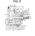
FIG. 5 is a fragmentary partially enlarged longitudinal sectional view of the compressor with the transmission ofFIG. 4 - The following will describe the compressor with the transmission according to the first and the second embodiments with reference to the accompanying drawings.
- As shown in
FIG. 1 , the compressor with the transmission (hereinafter referred to as compressor) according to the first embodiment includes a scroll-type compression mechanism 20, atransmission 30 and acontrol device 40 which are assembled together and is mounted on a vehicle as a part of an air conditioner. In each of the longitudinal views, the left-hand side and the right-hand side of the drawings correspond to the front and the rear of the compressor, respectively. - The compressor includes a
housing 10 including afirst housing 3, asecond housing 4, a third housing 5 and a fourth housing 6 which are connected together in this order. Rear end surface of thefirst housing 3 and front end surface of thesecond housing 4 are connected thereby to form therein atransmission chamber 10A which is filled with traction oil. Thefirst housing 3 has formed therethrough apassage 3A through which traction oil is introduced from outer peripheral region of thetransmission chamber 10A to the center thereof. - The third housing 5 has a
fixed scroll 21 integrally formed therewith. Thesecond housing 4 and the third housing 5 cooperate to house therein amovable scroll 22. Thefixed scroll 21 and themovable scroll 22 will be described later. The third housing 5 and the fourth housing 6 are connected each other thereby to form therebetween asuction chamber 28 and adischarge chamber 29. - An input shaft 1 is rotatable on an axis O1 thereof and supported by a boss of the
first housing 3 through a seal member 7 and abearing 8. Thebearing 8 is pressed into thefirst housing 3 with a clearance formed between thebearing 8 and the input shaft 1. Akey 15 is provided between anoutput shaft 2 and asun roller 14 that forms a part of thetransmission 30. The provision of the clearance and thekey 15 allows an assembly S including the input shaft 1, a carrier 9, aradial bearing 31, a plurality ofplanetary rollers 32, thesun roller 14, aring roller 33, afriction layer 35, acirclip 34A and a one-way clutch 34 to move as a unit in the direction that is parallel to theaxis 01 relative to thefirst housing 3. - Rear end of the input shaft 1 extends rearward in the
transmission chamber 10A and the input shaft 1 is formed integrally with acarrier body 9A in the form of a disc located adjacently to the rear end of the input shaft 1 and extending radially outward from the input shaft 1 in facing relation to the inner surface of thefirst housing 3 so as to have a clearance between the carrier body 9Aand the inner surface,of thefirst housing 3. Thecarrier body 9A forms a part of thetransmission 30 as will be described later. - The
output shaft 2 is rotatable on theaxis 01 and supported by a boss of thesecond housing 4 through aseal member 11 and aradial bearing 12. Front end of theoutput shaft 2 is located within thecarrier body 9A and aradial bearing 13 is provided between thecarrier body 9A and theoutput shaft 2. Apassage 1A is formed in the input shaft 1 for communicating with thepassage 3A formed in thefirst housing 3 and supplying traction oil to the radial bearing 13. Thesun roller 14 is mounted on theoutput shaft 2 at a position rearward of thecarrier body 9A. Theaforementioned key 15 is provided between theoutput shaft 2 and thesun roller 14 so that thesun roller 14 integrally rotates with theoutput shaft 2 and also that thesun roller 14 moves relative to theoutput shaft 2 in the direction parallel to theaxis 01. Thesun roller 14 also forms a part of thetransmission 30. Rear end of theoutput shaft 2 extends toward themovable scroll 22. - The following will describe the
compression mechanism 20. Adrive bush 23 integrally formed with a balancer and themovable scroll 22 are housed between thesecond housing 4 and the third housing 5. - The
drive bush 23 that is eccentrically fixed to the rear end of theoutput shaft 2 can rotate integrally with theoutput shaft 2. Aradial bearing 24 is provided on outer peripheral surface of thedrive bush 23. - The
movable scroll 22 includes aboss 22A that is rotatably supported by thedrive bush 23 through theradial bearing 24, a disc-shapedmovable end plate 22B formed integrally with theboss 22A and extending radially and amovable scroll wail 22C extending rearward from themovable end plate 22B in the direction parallel to the axis O1. - Three or more fixed pins 25A of the
rotation preventing device 25 are fixed to the rear surface of thesecond housing 4 in the direction parallel to theaxis 01. Additionally, the same number ofmovable pins 25B as that of the fixed pins 25A are fixed to themovable end plate 22B of themovable scroll 22 in the direction parallel to theaxis 01. Furthermore, the same number of movable rings 25C as that of the fixed pins 25A and themovable pins 25B are provided between thesecond housing 4 and themovable end plate 22B. The movable ring 25C has formed therethrough ahole 25D receiving therein a pair of the fixed pin 25A and themovable pin 25B with the axes thereof spaced away at a distance corresponding to the orbital radius of themovable scroll 22. The fixed pin 25A, themovable pin 25B and the movable ring 25C cooperate to form the aforementionedrotation preventing device 25 for preventing themovable scroll 22 from rotating on its axis. - As mentioned earlier, the
fixed scroll 21 is integrally formed with the third housing 5. The fixedscroll 21 includes a disc-shapedfixed end plate 21 B extending radially outward and a fixedscroll wall 21C extending frontward from the fixedend plate 21 B in the direction parallel to theaxis 01. - The fixed
scroll wall 21C of the fixedscroll 21 and themovable scroll wall 22C of themovable scroll 22 have the same length as measured in the direction parallel to the axis O1. The distal ends of the fixedscroll wall 21 C of the fixedscroll 21 and themovable scroll wall 22C of themovable scroll 22 are slidable on themovable end plate 22B and thefixed end plate 21B, respectively. - The
fixed end plate 21 B has formed therethrough at the center thereof a discharge port 29Athat is communicable with adischarge chamber 29. Adischarge valve 26 and aretainer 27 are fixed to thefixed end plate 21 B in thedischarge chamber 29 so as to close thedischarge port 29A. Thefixed end plate 21 B has formed therethrough in the outer peripheral portion thereof asuction port 28A communicating with asuction chamber 28. - The above second, third and
fourth housings 4, 5, 6, theoutput shaft 2, thedrive bush 23, themovable scroll 22, therotation preventing device 25 and the fixedscroll 21 cooperate to form the scroll-type compression mechanism 20. - The
discharge chamber 29 is connected to acondenser 42 by atube 41, thecondenser 42 is connected to anevaporator 45 through anexpansion valve 44 by atube 43 and theevaporator 45 is connected to thesuction chamber 28 by atube 46. A discharge-pressure supply passage (or channel Pd-Pd shown inFIG. 1 ) is provided for supplying a discharge pressure Pd in thedischarge chamber 29 to anelectromagnetic valve 61. Similarly, a suction-pressure supply passage (or channel Ps-Ps shown inFIG. 1 ) is provided for supplying a suction pressure Ps in thesuction chamber 28 to theelectromagnetic valve 61. Though not shown in the drawing, a passage is provided in the second and thethird housings 4, 5 for holding the pressure in thetransmission chamber 10A at a level of the suction pressure Ps by connecting thesuction chamber 28 and thetransmission chamber 10A. - The following will describe the
transmission 30. In thetransmission chamber 10A, foursupport shafts 9B extend rearward from positions on an imaginary circle centered on theaxis 01 on the rear surface of thecarrier body 9A that are adjacent to the outer periphery of thecarrier body 9A in parallel relation to the axis O1. Eachsupport shaft 9B is cylindrically-shaped. Each of the aforementionedplanetary rollers 32 is rotatably supported by thesupport shaft 9B through theradial bearing 31. Outer surface of theplanetary roller 32 engages with outer surface of itscorresponding sun roller 14 with interference therebetween. The outer surfaces of the respectiveplanetary rollers 32 and thesun roller 14 are coated so as to prevent slip therebetween. - A
rear carrier 9D is fixed to the rear end of eachsupport shaft 9B. Therear carrier 9D is substantially cylindrically-shaped and extending rearward. Thecarrier body 9A, therespective support shaft 9B and therear carrier 9D cooperate to rotatably support the fourplanetary rollers 32 and to form the carrier 9 that is integrally rotatable with the input shaft 1. - The
aforementioned ring roller 33 is provided between the respectiveplanetary roller 32 and the first and thesecond housings housing 10 in the direction parallel to the axis O1. As shown inFIG. 2 , thering roller 33 includes cylindrical first andsecond rings - The
first ring 331 is made of a material having a relatively low stiffness so as to be displaceable in a radial direction as shown inFIG. 3 . Therefore, thefirst ring 331 can be displaced in a radial direction by the interferences between thesun roller 14 and the respectiveplanetary roller 32 and also between the respectiveplanetary roller 32 and thering roller 33. Inner surface of thefirst ring 331 is also coated so as to prevent a slip between thefirst ring 331 and the respectiveplanetary rollers 32. - As shown in
FIG. 2 , the rear surface of thefirst ring 331 is stepped, having a firstrear surface 331A located on radially inner side thereof and a secondrear surface 331B located on radially outer side thereof. As shown inFIG. 2 , the secondrear surface 331 B is located rearward of the firstrear surface 331A so that thefirst ring 331 has an annularfirst step 331 C. Thefirst step 331 C has formed radially therethrough afirst ring hole 331 D. - The
second ring 332 is made of a material having a relatively high stiffness. Actually, the stiffness of thesecond ring 332 is higher than that of thefirst ring 331. As shown inFIG. 1 , the outer peripheral surface of the one-way clutch 34 is in contact with the inner peripheral surface of thesecond ring 332. - As shown in
FIG. 2 , the front end of thesecond ring 332 is stepped, having a firstfront surface 332A located on radially inner side thereof and a secondfront surface 332B located on radially outer side thereof. Thesecond ring 332 has asecond step 332C with the firstfront surface 332A located frontward of the secondfront surface 332B. Thesecond step 332C has formed therethrough in radial direction asecond ring hole 332D. Thesecond ring 332 has also formed at the front end thereof aflange 33A extending radially inward so as to be contactable with the rear end of the respectiveplanetary rollers 32. - A
shoulder pin 333 is inserted in thefirst ring hole 331 D of thefirst ring 331 and thesecond ring hole 332D of thesecond ring 332. Specifically, the head of theshoulder pin 333 is press-fitted in thefirst ring hole 331 D and the shaft of theshoulder pin 333 is loosely passed through thesecond ring hole 332D as shown inFIG. 2 . With theshoulder pin 333 thus inserted in thefirst ring hole 331 D and thesecond ring hole 332D as shown inFIG. 2 , the firstrear surface 331 A of thefirst ring 331 contacts with the firstfront surface 332A of thesecond ring 332 and a clearance is formed between the secondrear surface 331 B of thefirst ring 331 and the secondfront surface 332B of thesecond ring 332. Thefirst ring 331 and thesecond ring 332 are connected in this manner. - Thus, the
second ring 332 supports the one-way clutch 34 and is rotatable integrally with thefirst ring 331 and movable with thefirst ring 331 in the direction parallel to the axis O1 without being influenced by the displacement of thefirst ring 331 in radial direction. Even if thefirst ring 331 is displaced in radial direction, thesecond ring 332 maintains high accuracy in dimensions and cylindricality and gives no influence on the function of the one-way clutch 34. - As shown in
FIG. 1 , thesun roller 14, the respectiveplanetary rollers 32, thering roller 33 and the carrier 9 cooperate to form thetransmission 30 that is a planetary roller train. - The one-way clutch 34 that is a known clutch available on the market is fixed to the outer peripheral surface of the
rear carrier 9D by thecirclip 34A. The one-way clutch 34 allows thering roller 33 to rotate only in one direction relative to the carrier 9. In the present embodiment, it is so arranged that the input shaft 1 and the carrier 9 rotate on the axis O1 in clockwise direction as viewed from the front of the compressor. The one-way clutch 34 allows thering roller 33 to rotate only in counter-clockwise direction relative to the carrier 9 as viewed from the front of the compressor. - The
friction layer 35 is provided on front surface of thering roller 33 in facing relation to the rear surface of thefirst housing 3. Thefriction layer 35 is made of an annular flat plate having a low slide property. When thering roller 33 moves frontward, thefriction layer 35 contacts with the rear surface of thefirst housing 3. - A
control chamber 36 is formed in the front surface of thesecond housing 4 in the shape of an annular recess in facing relation to the rear surface of thering roller 33. Anannular control piston 37 is accommodated in thecontrol chamber 36 so as to slide in longitudinal direction of the compressor (or in the direction parallel to the axis O1). O-rings control piston 37 for sealing between thecontrol piston 37 and thecontrol chamber 36. - The
electromagnetic valve 61 as a pressure adjusting device is connected to thecontrol chamber 36 through apassage 36A. Theelectromagnetic valve 61 is operable to connect thecontrol chamber 36 selectively to the discharge-pressure supply passage (channel Pd-Pd shown inFIG. 1 ) or to the suction-pressure supply passage (channel Ps-Ps shown inFIG. 1 ). As previously described, the pressure in thetransmission chamber 10A facing thecontrol piston 37 is maintained at the suction pressure Ps. Athrust bearing 39 is located at the front of thecontrol piston 37 and rearward of thesecond ring 332. - The
friction layer 35, thecontrol chamber 36, thecontrol piston 37, thepassage 36A, thethrust bearing 39 and theelectromagnetic valve 61 cooperate to form a clutch 60 that fixes thering roller 33 to thefirst housing 3 or allows thering roller 33 to rotate relative to thefirst housing 3. The clutch 60, the one-way clutch 34, theelectromagnetic valve 61 and thepassage 36A cooperate to form thecontrol device 40. - An electromagnetic clutch 50 is connected to the front end of the input shaft 1. The
electromagnetic clutch 50 includes ahub 51 that is fixed to the front end of the input shaft 1 for rotating with the input shaft 1, anarmature 53 connected to thehub 51 through aleaf spring 52 and acoil 54 fixed to the front surface of thefirst housing 3. Apulley 56 is rotatably supported by a boss of thefirst housing 3 through aradial bearing 55. Thepulley 56 is coupled to an engine as an external drive source through a belt. Thecoil 54 is provided inside thepulley 56. - When the
coil 54 of theelectromagnetic clutch 50 is energized, thearmature 53 is attracted to thepulley 56 against elastic force of theleaf spring 52 and the input shaft 1 is integrally rotated with thepulley 56, so that the torque of the engine is transmitted to the input shaft 1. The rotation of the input shaft 1 around theaxis 01 is transmitted at the same or increased speed to theoutput shaft 2. - On the other hand, when the
coil 54 is deenergized, thearmature 53 is separated from thepulley 56 by the elastic force of theleaf spring 52 and the torque transmission to the input shaft 1 is shut off. Thus, the drive force from the external engine is connected or disconnected by theelectromagnetic clutch 50. - When the
output shaft 2 is driven to rotate, thedrive bush 23 whose axis is eccentric to the axis of theoutput shaft 2 is rotated and themovable scroll 22 make an orbital motion while being prevented from rotating around its axis by therotation preventing device 25 in thecompression mechanism 20. With the orbital motion of themovable scroll 22, a compression chamber that is formed between the fixedscroll 21 and themovable scroll 22 is progressively reduced in volume from outer side of thecompression mechanism 20 to the center thereof. Thus, refrigerant drawn into the compression chamber from thesuction chamber 28 is compressed and discharged into thedischarge chamber 29. Refrigerant in thedischarge chamber 29 is delivered to thecondenser 42 and air-conditioning for a compartment of the vehicle is accomplished by allowing the refrigerant to be evaporated by theevaporator 45. - Meanwhile, when the discharge pressure Pd is applied to the
control chamber 36 and the pressure in thecontrol chamber 36 is increased higher than that in thetransmission chamber 10A, thecontrol piston 37 is moved frontward. Accordingly, thecontrol piston 37 moves frontward thesecond ring 332, which moves frontward and urges thefirst ring 331 against thefirst housing 3. That is, thecontrol piston 37 urges the aforementioned assembly S as a unit frontward through thering roller 33. Thering roller 33 is pressed securely against thefirst housing 3 due to high friction between thefriction layer 35 and thefirst housing 3. - Then, the one-way clutch 34 allows the
ring roller 33 to rotate relative to the carrier 9 only in one direction (i.e. in counter-clockwise direction as viewed from the front of the compressor). In accordance with the rotation of the input shaft 1 and the carrier 9, the respectiveplanetary rollers 32 that orbit around theaxis 01 in clockwise direction rotate around their correspondingsupport shafts 9B in counter-clockwise direction due to the interference between the respectiveplanetary rollers 32 and thefirst ring 331. As a result, thesun roller 14 engaged with the respectiveplanetary rollers 32 and theoutput shaft 2 rotatable integrally with thesun roller 14 are rotated at a higher speed than that of the input shaft 1. Thus, the rotation of the input shaft 1 is transmitted at an increased speed to theoutput shaft 2. - On the other hand, when the suction pressure Ps is applied to the
control chamber 36 and the pressure in thecontrol chamber 36 becomes the same as that in thetransmission chamber 10A, thecontrol piston 37 no longer urges thering roller 33 against thefirst housing 3. Since thecontrol piston 37 no longer urges the assembly S frontward through thering roller 33, thefriction layer 35 and thefirst housing 3 are disengaged from each other and the friction force therebetween no longer works. Thus, thering roller 33 can rotate relative to thefirst housing 3 and rolls by thethrust bearing 39. - In the compressor, the respective
planetary rollers 32 move thesecond ring 332 in the direction parallel to theaxis 01 easily via theflange 33A. Thefirst ring 331 is also moved in the same direction easily. Thering roller 33 attempts to rotate with the input shaft 1 around theaxis 01 in a clockwise direction. Since the respectiveplanetary rollers 32 in contact with thesun roller 14 rotate around its axis in clockwise direction, thering roller 33 attempts to rotate in clockwise direction faster than the input shaft 1. However, the one-way clutch 34 prevents thering roller 33 from rotating relative to the carrier 9 in clockwise direction as viewed from the front of the compressor. Thethrust bearing 39 prevents thering roller 33 from dragging thecontrol piston 37. Therefore, the input shaft1, the carrier 9, the respectiveplanetary rollers 32, thesun roller 14, thering roller 33 and theoutput shaft 2 are rotatable integrally as a unit, and the rotation of the input shaft 1 is transmitted at the same speed to theoutput shaft 2. - Thus, the compressor that employs the
transmission 30 made of the planetary roller train causes less vibration and less noise. Though the compressor can change the rotating speed of the input shaft 1 into two different speeds of theoutput shaft 2, it can be manufactured at a low cost due to the simplified structure. - Therefore, the compressor according to the present embodiment of the present invention can accomplish the reduction of manufacturing cost and noise development.
- The compressor according to the second embodiment shown in
FIGS. 4 and5 differs from the compressor according to the first embodiment in that aring roller 72, aplanetary roller 71 and asun roller 73 are used in place of thering roller 33, theplanetary roller 32 and thesun roller 14, respectively, of the compressor according to the first embodiment. Specifically, thering roller 72 includes afirst ring 721, thesecond ring 332 and theshoulder pin 333. Inner surface of thefirst ring 721 is formed in a tapered shape rearwardly. Accordingly, the outer surfaces of respectiveplanetary rollers 71 are formed in a tapered shape rearwardly. The outer surface of thesun roller 73 is formed in a tapered shape frontwardly. - The
first ring 721 has formed on the front outer peripheral surface thereof a flange 721Aextending radially outward, and aleaf spring 74 is provided between thefirst housing 3 and theflange 721A for urging thering roller 72 rearward. Theleaf spring 74 corresponds to the urging device of the present invention. Afriction layer 75 is provided on the rear surface of thefirst housing 3 so as to face theleaf spring 74. Thepassage 3A formed in thefirst housing 3 extends through thefriction layer 75. The following description will use the same reference numerals for the common elements in the first and the second embodiments, and the description of such elements or components will be omitted. - When the
control piston 37 moves thesecond ring 332 frontward by the discharge pressure Pd, the interferences between thefirst ring 721 and the respectiveplanetary rollers 71 and between the respectiveplanetary rollers 71 and thesun roller 73 increase. In other words, when the rotating speed of theoutput shaft 2 is increased higher than that of the input shaft 1 and the torque transmitted is increased, the respective interferences increase. - On the other hand, when the
second ring 332 is moved rearward, the interferences between thefirst ring 721 and the respectiveplanetary rollers 71 and between the respectiveplanetary rollers 71 and thesun roller 73 decrease, respectively. In other words, when the rotating speed of theoutput shaft 2 is the same as that of the input shaft 1 and the torque transmitted to theoutput shaft 2 is decreased, the respective interferences decrease. - The interference changes in accordance with the torque to be transmitted in the compressor according to the second embodiment and the power loss changes, accordingly. Thus, the compressor accomplishes reduction in power loss. Since the
first ring 721 is urged by the high discharge pressure Pd, the torque can be transmitted steadily by the increased interference when the rotating speed of theoutput shaft 2 is higher than that of the input shaft 1. - The compressor according to the second embodiment wherein the
leaf spring 74 helps to reduce power loss can accomplish the reduction in power loss during compressor operation other than when the rotating speed of theoutput shaft 2 is higher than that of the input shaft 1. The second embodiment offers the same advantageous effects as the first embodiment. - The present invention is not limited to the first and the second embodiments and the invention may be practiced in various manners within the scope of the invention.
- The compression mechanism is not limited to a scroll-type mechanism but may employ a general type of compression mechanism such as piston type compression mechanism. The clutch may include a link mechanism composed of a plurality of movable members.
- The present invention can be used for a vehicle air conditioner.
- A compressor includes a housing, a compression mechanism formed in the housing and operable to compress refrigerant, an input shaft extending into the housing from outside and rotatably supported on an axis of the input shaft, an output shaft extending in the housing and rotatably supported on the axis for driving the compression mechanism, a transmission provided in the housing between the input shaft and the output shaft for transmitting torque from the input shaft to the output shaft and also changing the rotating speed of the input shaft into two different speeds of the output shaft for driving the compression mechanism by increasing or remaining the rotating speed of the input shaft and a control device. The transmission includes a plurality of planetary rollers, a carrier rotatably supporting the respective planetary rollers and being integrally rotatable with the input shaft, a sun roller engaged with the respective planetary rollers and integrally rotatable with the output shaft and a ring roller engaged with the respective planetary rollers. The ring roller can be fixed to the housing or rotatable relative to the housing. The control device provided between the carrier and the ring roller for controlling the operation of the transmission includes a one-way clutch provided between the ring roller and the carrier and allowing the ring roller to rotate only one direction relative to the carrier and a clutch provided between the housing and the ring roller, the clutch fixing the ring roller to the housing or allowing the ring roller to rotate relative to the housing. The ring roller includes a first ring engaged with the respective planetary rollers and a second ring supporting the one-way clutch. The ring roller can be movable relative to the housing in the direction parallel to the axis. The first ring and the second ring are connected so that the first ring can be displaced in a radial direction, integrally rotatable with the second ring and movable with the second ring in the direction parallel to the axis.
Claims (8)
- A compressor comprising:a housing (10);a compression mechanism (20) formed in the housing (10) and operable to compress refrigerant;an input shaft (1) supported by the housing, the input shaft extending into the housing (10) from outside and rotatable on an axis (O1) of the input shaft (1);an output shaft (2) supported by the housing, the output shaft extending in the housing (10) and rotatable on the axis (O1) for driving the compression mechanism (20); anda transmission (30) provided in the housing (10) between the input shaft (1) and the output shaft (2) for transmitting torque from the input shaft (1) to the output shaft (2) and also changing the rotating speed of the input shaft (1) into two different speeds of the output shaft (2) for driving the compression mechanism (20) by at the same or increased rotating speed; characterized in that the transmission (30) including:a plurality of planetary rollers (32, 71);a carrier (9) rotatably supporting the respective planetary rollers (32, 71) and integrally rotatable with the input shaft (1);a sun roller (14, 73) engaged with the respective planetary rollers (32, 71) and integrally rotatable with the output shaft (2); anda ring roller (33, 72) engaged with the respective planetary rollers (32, 71), the ring roller (33, 72) which can be fixed to the housing (10) or rotatable relative to the housing (10), wherein the compressor further comprising:a control device (40) provided between the carrier (9) and the ring roller (33, 72) for controlling the operation of the transmission (30), the control device (40) including:a one-way clutch (34) provided between the ring roller (33, 72) and the carrier (9) and allowing the ring roller (33, 72) to rotate only one direction relative to the carrier (9); anda clutch (60) provided between the housing (10) and the ring roller (33, 72), the clutch (60) fixing the ring roller (33, 72) to the housing (10) or allowing the ring roller (33, 72) to rotate relative to the housing (10), wherein the ring roller (33, 72) including:a first ring (331, 721) engaged with the respective planetary rollers (32, 71); anda second ring (332) supporting the one-way clutch (34), wherein the ring roller (33, 72) can be movable relative to the housing (10) in the direction parallel to the axis (01), wherein the first ring (331, 721) and the second ring (332) are connected so that the first ring (331, 721) can be displaced in a radial direction, integrally rotatable with the second ring (332) and movable with the second ring (332) in the direction parallel to the axis (01).
- The compressor according to claims 1, characterized in that the stiffness of the second ring (332) is higher than that of the first ring (331, 721).
- The compressor according to any one of claims 1 through 2, characterized in that the clutch (60) provided between the housing (10) and the first ring (331) including:a friction layer (35, 75) that can fix the ring roller (33, 72) to the housing (10) or release the ring roller (33, 72) relative to the housing (10) by the movement of the second ring (332);a control chamber (36) formed in the housing (10) in facing relation to the second ring (332);a control piston (37) accommodated in the control chamber (36) so as to slide in the direction parallel to the axis (O1);a thrust bearing (39) provided between the control piston (37) and the second ring (332); anda pressure adjusting device (61) that moves the control piston (37) by applying a pressure to the control chamber (36).
- The compressor according to claim 3, characterized in that the pressure adjusting device is operable to connect the control chamber (36) selectively to a discharge pressure or to a suction pressure, wherein a pressure in a transmission chamber (10A) accommodating the transmission (30) is held at a level of the suction pressure.
- The compressor according to any one of claims 1 through 4, characterized in that the first ring (331) including:a first rear surface (331A) located on radially inner side of the first ring (331);a second rear surface (331B) located on radially outer side of the first ring (331);a first step (331C) formed so that the second rear surface (331B) is located rearward of the first rear surface (331A); anda first ring hole (331D) formed radially through the first step (331C), wherein the second ring (332) including:a first front surface (332A) located on radially inner side of the second ring (332);a second front surface (332B) located on radially outer side of the second ring (332);a second step (332C) formed so that the first front surface (332A) is located frontward of the second front surface (332B);a second ring hole (332D) formed radially through the second step (332C); anda flange (33A) that is formed at front end of the second ring (332) extending radially inward so as to be contactable with rear end of the respective planetary rollers, wherein the ring roller (33, 72) further including a shoulder pin (333) whose head is press-fitted in the first ring hole (331 D) and whose shaft is loosely passed through the second ring hole (332D), wherein the first rear surface (331A) of the first ring (331) contacts with the first front surface (332A) of the second ring (332) and a clearance is formed between the second rear surface (331 B) of the first ring (331) and the second front surface (332B) of the second ring (332).
- The compressor according to any one of claims 1 through 5, characterized in that inner surface of first ring (721) and outer surfaces of respective planetary rollers (71) are formed in a tapered shape rearwardly and outer surface of sun roller (73) is formed in a tapered shape frontwardly so that the interferences between the first ring (721) and the respective planetary rollers (71) and between the respective planetary rollers (71) and the sun roller (73) increase when the second ring (332) moves frontward for fixing the first ring (721) to the housing (10) and so that the interferences between the first ring (721) and the respective planetary rollers (71) and between the respective planetary rollers (71) and the sun roller (73) decrease when the second ring (332) moves rearward for releasing the first ring (721) relative to the housing (10).
- The compressor according to claim 6, characterized in that the compressor further comprising:an urging device (74) provided between the housing (10) and the first ring (721) for urging the first ring (721) rearward so that the interferences decrease.
- The compressor according to any one of claims 1 through 7, characterized in that the compressor further comprising:a key (15) provided between the output shaft (2) and the sun roller (14, 73) so that the sun roller (14, 73) integrally rotates with the output shaft (2) and moves relative to the output shaft (2) in the direction parallel to the axis (01); anda bearing (8) provided in the housing (10) for rotatably supporting the input shaft (1) with a clearance formed between the bearing (8) and the input shaft (1).
Applications Claiming Priority (1)
| Application Number | Priority Date | Filing Date | Title |
|---|---|---|---|
| JP2010080367A JP5310630B2 (en) | 2010-03-31 | 2010-03-31 | Compressor with transmission |
Publications (2)
| Publication Number | Publication Date |
|---|---|
| EP2375077A2 true EP2375077A2 (en) | 2011-10-12 |
| EP2375077A3 EP2375077A3 (en) | 2016-08-10 |
Family
ID=44069188
Family Applications (1)
| Application Number | Title | Priority Date | Filing Date |
|---|---|---|---|
| EP11158668.1A Withdrawn EP2375077A3 (en) | 2010-03-31 | 2011-03-17 | Compressor with transmission |
Country Status (3)
| Country | Link |
|---|---|
| US (1) | US8517880B2 (en) |
| EP (1) | EP2375077A3 (en) |
| JP (1) | JP5310630B2 (en) |
Families Citing this family (7)
| Publication number | Priority date | Publication date | Assignee | Title |
|---|---|---|---|---|
| JP5477113B2 (en) * | 2010-03-31 | 2014-04-23 | 株式会社豊田自動織機 | Compressor with transmission |
| DE102011114046A1 (en) * | 2011-09-22 | 2013-03-28 | Knorr-Bremse Systeme für Nutzfahrzeuge GmbH | Compressor system and method of operating a compressor system |
| CN102536813B (en) * | 2011-11-05 | 2015-11-25 | 佛山市广顺电器有限公司 | A kind of scroll compressor of automobile air conditioner |
| US9441599B2 (en) * | 2012-07-17 | 2016-09-13 | Altigreen Propulsion Labs Private Limited | Induction motor-permanent magnet generator tandem configuration starter-generator for hybrid vehicles |
| US9580065B2 (en) | 2012-07-17 | 2017-02-28 | Altigreen Propulsion Labs Private Limited | Dual-structured electric drive and power system for hybrid vehicles |
| DE102014202494B4 (en) * | 2013-12-20 | 2022-12-22 | Zf Friedrichshafen Ag | Planetary gear with adjustable ring gear |
| CN114607596B (en) * | 2022-03-30 | 2022-12-02 | 山东科技大学 | A non-supplementary combustion scroll compression expansion integrated multi-shaft output device |
Citations (1)
| Publication number | Priority date | Publication date | Assignee | Title |
|---|---|---|---|---|
| JP2007107412A (en) | 2005-10-12 | 2007-04-26 | Toyota Industries Corp | Compressor with transmission |
Family Cites Families (11)
| Publication number | Priority date | Publication date | Assignee | Title |
|---|---|---|---|---|
| US4158972A (en) * | 1978-02-21 | 1979-06-26 | Caterpillar Tractor Co. | Ring gear positioner |
| US5931759A (en) * | 1997-05-09 | 1999-08-03 | Nsk Ltd. | Friction-roller speed changer |
| JP3763398B2 (en) | 2001-02-13 | 2006-04-05 | 株式会社ジェイテクト | Planetary roller transmission |
| JP2004156532A (en) * | 2002-11-06 | 2004-06-03 | Toyota Industries Corp | Variable capacity mechanism in scroll compressor |
| JP2005307835A (en) * | 2004-04-20 | 2005-11-04 | Toyota Industries Corp | Compressor with transmission |
| JP3950456B2 (en) * | 2004-06-10 | 2007-08-01 | 三菱重工業株式会社 | Planetary roller type continuously variable transmission |
| JP4360984B2 (en) * | 2004-07-22 | 2009-11-11 | 株式会社デンソー | Auxiliary equipment driven by engine |
| DE102005051428B4 (en) * | 2004-10-29 | 2015-05-28 | Denso Corporation | Waste heat recovery device |
| CN101389873B (en) * | 2005-12-27 | 2010-12-29 | 三菱重工业株式会社 | Planetary roller speed reducer |
| JP4889318B2 (en) * | 2006-02-23 | 2012-03-07 | 日本電産シンポ株式会社 | Lubricating structure of planetary reducer |
| JP2011002034A (en) * | 2009-06-18 | 2011-01-06 | Toyota Motor Corp | Forward movement and backward movement change-over device for vehicle |
-
2010
- 2010-03-31 JP JP2010080367A patent/JP5310630B2/en not_active Expired - Fee Related
-
2011
- 2011-03-16 US US13/049,107 patent/US8517880B2/en not_active Expired - Fee Related
- 2011-03-17 EP EP11158668.1A patent/EP2375077A3/en not_active Withdrawn
Patent Citations (1)
| Publication number | Priority date | Publication date | Assignee | Title |
|---|---|---|---|---|
| JP2007107412A (en) | 2005-10-12 | 2007-04-26 | Toyota Industries Corp | Compressor with transmission |
Also Published As
| Publication number | Publication date |
|---|---|
| US20110245004A1 (en) | 2011-10-06 |
| EP2375077A3 (en) | 2016-08-10 |
| JP2011214415A (en) | 2011-10-27 |
| JP5310630B2 (en) | 2013-10-09 |
| US8517880B2 (en) | 2013-08-27 |
Similar Documents
| Publication | Publication Date | Title |
|---|---|---|
| US8517880B2 (en) | Compressor with transmission | |
| EP1887224B1 (en) | Power transmission mechanism | |
| US6796126B2 (en) | Supercharger | |
| CN103459891B (en) | Friction roller reducer and drive unit for electric vehicles | |
| US8574116B2 (en) | Compressor with transmission | |
| US20120251347A1 (en) | Compressor with transmission | |
| US20090047162A1 (en) | Compressor and Power Transmission Device | |
| JP2009505026A (en) | Electronically controlled torque directing shaft | |
| JPH1193876A (en) | Combined compression device | |
| US20050233854A1 (en) | Variable speed compressor | |
| JPH01210653A (en) | Continuously variable transmission | |
| JP2012026413A (en) | Compressor with transmission | |
| JP2011214426A (en) | Compressor with transmission | |
| JP2011214421A (en) | Compressor with transmission | |
| JP2011214594A (en) | Compressor with transmission | |
| EP1406013B1 (en) | Variable displacement swash plate type compressor | |
| JP4432956B2 (en) | Combined compression device | |
| JP4513246B2 (en) | Friction roller transmission and friction roller transmission with motor | |
| JP2011214416A (en) | Compressor with transmission | |
| JP2007107412A (en) | Compressor with transmission | |
| JP2011214409A (en) | Compressor with transmission | |
| JP2008111519A (en) | Bearing structure for rotary machine | |
| JP2005330876A (en) | Compressor with transmission | |
| JP2004156531A (en) | Friction roller type transmission integrated compressor | |
| JP2004169551A (en) | Hybrid type compressor |
Legal Events
| Date | Code | Title | Description |
|---|---|---|---|
| PUAI | Public reference made under article 153(3) epc to a published international application that has entered the european phase |
Free format text: ORIGINAL CODE: 0009012 |
|
| 17P | Request for examination filed |
Effective date: 20110317 |
|
| AK | Designated contracting states |
Kind code of ref document: A2 Designated state(s): AL AT BE BG CH CY CZ DE DK EE ES FI FR GB GR HR HU IE IS IT LI LT LU LV MC MK MT NL NO PL PT RO RS SE SI SK SM TR |
|
| AX | Request for extension of the european patent |
Extension state: BA ME |
|
| PUAL | Search report despatched |
Free format text: ORIGINAL CODE: 0009013 |
|
| AK | Designated contracting states |
Kind code of ref document: A3 Designated state(s): AL AT BE BG CH CY CZ DE DK EE ES FI FR GB GR HR HU IE IS IT LI LT LU LV MC MK MT NL NO PL PT RO RS SE SI SK SM TR |
|
| AX | Request for extension of the european patent |
Extension state: BA ME |
|
| RIC1 | Information provided on ipc code assigned before grant |
Ipc: F16D 11/00 20060101ALI20160701BHEP Ipc: F04C 29/00 20060101AFI20160701BHEP |
|
| STAA | Information on the status of an ep patent application or granted ep patent |
Free format text: STATUS: THE APPLICATION IS DEEMED TO BE WITHDRAWN |
|
| 18D | Application deemed to be withdrawn |
Effective date: 20170211 |