EP2375073A1 - Sealing for the control chamber of a variable displacement lubricant pump - Google Patents
Sealing for the control chamber of a variable displacement lubricant pump Download PDFInfo
- Publication number
- EP2375073A1 EP2375073A1 EP10158810A EP10158810A EP2375073A1 EP 2375073 A1 EP2375073 A1 EP 2375073A1 EP 10158810 A EP10158810 A EP 10158810A EP 10158810 A EP10158810 A EP 10158810A EP 2375073 A1 EP2375073 A1 EP 2375073A1
- Authority
- EP
- European Patent Office
- Prior art keywords
- control ring
- housing
- variable displacement
- bar
- lubricant pump
- Prior art date
- Legal status (The legal status is an assumption and is not a legal conclusion. Google has not performed a legal analysis and makes no representation as to the accuracy of the status listed.)
- Withdrawn
Links
Images

Classifications
-
- F—MECHANICAL ENGINEERING; LIGHTING; HEATING; WEAPONS; BLASTING
- F16—ENGINEERING ELEMENTS AND UNITS; GENERAL MEASURES FOR PRODUCING AND MAINTAINING EFFECTIVE FUNCTIONING OF MACHINES OR INSTALLATIONS; THERMAL INSULATION IN GENERAL
- F16N—LUBRICATING
- F16N13/00—Lubricating-pumps
-
- F—MECHANICAL ENGINEERING; LIGHTING; HEATING; WEAPONS; BLASTING
- F01—MACHINES OR ENGINES IN GENERAL; ENGINE PLANTS IN GENERAL; STEAM ENGINES
- F01C—ROTARY-PISTON OR OSCILLATING-PISTON MACHINES OR ENGINES
- F01C19/00—Sealing arrangements in rotary-piston machines or engines
- F01C19/005—Structure and composition of sealing elements such as sealing strips, sealing rings and the like; Coating of these elements
-
- F—MECHANICAL ENGINEERING; LIGHTING; HEATING; WEAPONS; BLASTING
- F04—POSITIVE - DISPLACEMENT MACHINES FOR LIQUIDS; PUMPS FOR LIQUIDS OR ELASTIC FLUIDS
- F04C—ROTARY-PISTON, OR OSCILLATING-PISTON, POSITIVE-DISPLACEMENT MACHINES FOR LIQUIDS; ROTARY-PISTON, OR OSCILLATING-PISTON, POSITIVE-DISPLACEMENT PUMPS
- F04C14/00—Control of, monitoring of, or safety arrangements for, machines, pumps or pumping installations
- F04C14/18—Control of, monitoring of, or safety arrangements for, machines, pumps or pumping installations characterised by varying the volume of the working chamber
- F04C14/22—Control of, monitoring of, or safety arrangements for, machines, pumps or pumping installations characterised by varying the volume of the working chamber by changing the eccentricity between cooperating members
- F04C14/223—Control of, monitoring of, or safety arrangements for, machines, pumps or pumping installations characterised by varying the volume of the working chamber by changing the eccentricity between cooperating members using a movable cam
- F04C14/226—Control of, monitoring of, or safety arrangements for, machines, pumps or pumping installations characterised by varying the volume of the working chamber by changing the eccentricity between cooperating members using a movable cam by pivoting the cam around an eccentric axis
-
- F—MECHANICAL ENGINEERING; LIGHTING; HEATING; WEAPONS; BLASTING
- F04—POSITIVE - DISPLACEMENT MACHINES FOR LIQUIDS; PUMPS FOR LIQUIDS OR ELASTIC FLUIDS
- F04C—ROTARY-PISTON, OR OSCILLATING-PISTON, POSITIVE-DISPLACEMENT MACHINES FOR LIQUIDS; ROTARY-PISTON, OR OSCILLATING-PISTON, POSITIVE-DISPLACEMENT PUMPS
- F04C15/00—Component parts, details or accessories of machines, pumps or pumping installations, not provided for in groups F04C2/00 - F04C14/00
- F04C15/0003—Sealing arrangements in rotary-piston machines or pumps
- F04C15/0034—Sealing arrangements in rotary-piston machines or pumps for other than the working fluid, i.e. the sealing arrangements are not between working chambers of the machine
-
- F—MECHANICAL ENGINEERING; LIGHTING; HEATING; WEAPONS; BLASTING
- F04—POSITIVE - DISPLACEMENT MACHINES FOR LIQUIDS; PUMPS FOR LIQUIDS OR ELASTIC FLUIDS
- F04C—ROTARY-PISTON, OR OSCILLATING-PISTON, POSITIVE-DISPLACEMENT MACHINES FOR LIQUIDS; ROTARY-PISTON, OR OSCILLATING-PISTON, POSITIVE-DISPLACEMENT PUMPS
- F04C2/00—Rotary-piston machines or pumps
- F04C2/30—Rotary-piston machines or pumps having the characteristics covered by two or more groups F04C2/02, F04C2/08, F04C2/22, F04C2/24 or having the characteristics covered by one of these groups together with some other type of movement between co-operating members
- F04C2/34—Rotary-piston machines or pumps having the characteristics covered by two or more groups F04C2/02, F04C2/08, F04C2/22, F04C2/24 or having the characteristics covered by one of these groups together with some other type of movement between co-operating members having the movement defined in groups F04C2/08 or F04C2/22 and relative reciprocation between the co-operating members
- F04C2/344—Rotary-piston machines or pumps having the characteristics covered by two or more groups F04C2/02, F04C2/08, F04C2/22, F04C2/24 or having the characteristics covered by one of these groups together with some other type of movement between co-operating members having the movement defined in groups F04C2/08 or F04C2/22 and relative reciprocation between the co-operating members with vanes reciprocating with respect to the inner member
- F04C2/3441—Rotary-piston machines or pumps having the characteristics covered by two or more groups F04C2/02, F04C2/08, F04C2/22, F04C2/24 or having the characteristics covered by one of these groups together with some other type of movement between co-operating members having the movement defined in groups F04C2/08 or F04C2/22 and relative reciprocation between the co-operating members with vanes reciprocating with respect to the inner member the inner and outer member being in contact along one line or continuous surface substantially parallel to the axis of rotation
- F04C2/3442—Rotary-piston machines or pumps having the characteristics covered by two or more groups F04C2/02, F04C2/08, F04C2/22, F04C2/24 or having the characteristics covered by one of these groups together with some other type of movement between co-operating members having the movement defined in groups F04C2/08 or F04C2/22 and relative reciprocation between the co-operating members with vanes reciprocating with respect to the inner member the inner and outer member being in contact along one line or continuous surface substantially parallel to the axis of rotation the surfaces of the inner and outer member, forming the working space, being surfaces of revolution
Definitions
- the present invention refers to a variable displacement lubricant pump for an internal combustion engine.
- the pump is provided with a housing, a shiftable control ring inside the housing, and a seal sealing a control chamber defined by the housing and the control ring.
- Variable displacement lubricant pumps of the prior art are known from US 6 375 435 B2 . These pumps comprise a housing, a shiftable control ring inside the housing, and a seal which is sealing a first pressure zone in the control chamber from a second pressure zone.
- the plastic seal bar is seated in a respective slot and is biased radially towards the control ring by a spring which is positioned in the slot so that the seal is permanently in contact with the outer surface of the control ring.
- the plastic seal is permanently in transversal motion and in contact with the control ring and the slot wall so that an abrasion of the seal cannot be avoided and can lead to a leakage. As a consequence the accuracy of the lubricant pressure controlled by the pump, decreases.
- the spring causes also a pretensioning of the plastic seal bar, whereby the spring acts at certain points, i.e. the points where the spring is seating. As a consequence, the pretension force distribution is not equal over the length of the plastic seal bar.
- the assembly of such a pump with a seal which is supported by a spring is not cost-efficient.
- the variable displacement lubricant pump is provided with a housing and a shiftable and basically circular control ring inside the housing.
- a seal is sealing a control chamber which is defined by the housing and the control ring. With the control chamber the position of the control ring is controlled.
- the control ring pivots at a pivot axis so that the control ring is shifted between a low and a high pump chamber volume position.
- the seal is provided with a stiff bar and an elastomeric stripe fixed to the stiff bar, whereby the stiff bar is sliding at an inner surface of the housing and whereby the elastomeric stripe is attached to the outer surface of the control ring.
- This wording includes the inverse arrangement, i.e. the stiff bar is sliding at an outer surface of the control ring and the elastomeric stripe being attached to the inner surface of the housing.
- the elastomeric stripe of the seal provides a radial pretensioning of the stiff bar with a homogenous longitudinally force distribution so that the force which pushes the stiff bar against the inner surface of the housing ring is the same at every point of the stiff bar. Therefore, the pump provides an improved pressure control quality.
- the stiff bar is a plastic bar, wherein the stiff plastic bar is made out of a thermoplastic elastomer, thermoplastic and/or thermosetting plastic.
- Plastic materials have many desirable technical properties like hardness, elasticity, heat resistance and chemical resistance, for instance, which are adaptable in a broad range.
- the stiff bar is a metal bar and the metal bar is made out of steel.
- a contact between the stiff metal bar and the metal housing wall provides a good sealing property.
- the abrasion of the stiff metal bar is reduced significantly so that the seal provides a good long time durability.
- steel is an alloy with numerous advantages properties depending on the composition of the steel. The metal bar steel should have an optimal ratio of ductility and stiffness, and good sliding and abrasion properties.
- the elastomeric stripe is co-molded to the sliding stiff bar.
- the co-molding of the elastomeric part and the stiff part provides a one-piece seal which is fluid-tight, strong enough to withstand the wear of the relative motion and which simplifies the mounting procedure,
- the elastomeric stripe is form-fitted hold in a corresponding slot of the control ring (or of the housing).
- the elastomeric stripe is provided with parallel longitudinal side walls and is preferably rectangular.
- the elastomeric stripe is arranged in a form-fitted slot of the control ring (or of the housing).
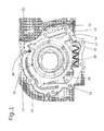
- a variable displacement lubricant pump 10 for an internal combustion engine is shown.
- the lubricant pump 10 is for supplying an internal combustion engine with a lubricant, and more particularly, with lubricant with a constant pressure.
- the variable displacement lubricant pump 10 comprises a metal housing 12 in which a shiftable control ring 14 is arranged axially between two side walls (not shown).
- the control ring 14 is provided with a pivot axis 26 at which the control ring 14 pivots, so that the control ring 14 is shifted between a low and a high pump chamber volume position.
- the metal housing 12 contains a rotor ring 28 with numerous radially slideable vanes 30, whereby the slidable vanes 30 are rotating inside the shiftable control ring 14.
- the control ring 14 surrounds a few pump chamber sections separated by the vanes 30.
- the rotor ring 28 is provided with a protrusion (not shown) which protrudes axially to the outside of one of the side walls. The protrusion of the rotor ring 28 can be rotated by a pump actuator which is not shown.
- the variable displacement lubricant pump 10 comprises two control chambers 20, 22 which are formed by the housing 12 and the control ring 14, respectively.
- the control chambers 20, 22 are opposed to each other with respect to the pivot axis 26 of the control ring 14. Both control chambers 20, 22 provide different pressures with respect to a third chamber 32 under atmospheric pressure.
- the control chambers 20, 22 are sealed by seals 16 against the third chamber 32.
- the seals 16 are form-fitted hold in respective axial slots 24 of the control ring 14.
- the seals 16 comprise a stiff bar 17 and an elastomeric stripe 18 which is preferably made out of a lubricant inert plastic.
- the elastomeric stripe 18 is co-molded to the sliding stiff bar 17.
- the co-molding can be realized by an adhesive or by any other means and methods known to an expert which lead to a strong and fluid-tight connection.
- the slots 24 or the seals 16, respectively are positioned so that the stiff bar 17 of the seal 16 is parallel and vis-à-vis to the pivot axis 26 of the control ring 14.
- the seal 16 is moving on a constant radius with respect to the pivot axis 26, when the control ring 14 is shifted.
- variable displacement lubricant pump 10 is assembled first by inserting the seals 16 into the corresponding slots 24 of the control ring 14. After that, the control ring 14 is mounted to the housing 12 of the pump 10, thereby compressing the elastomeric stripe 18 of the seal 16.
Landscapes
- Engineering & Computer Science (AREA)
- General Engineering & Computer Science (AREA)
- Mechanical Engineering (AREA)
- Details And Applications Of Rotary Liquid Pumps (AREA)
- Lubrication Of Internal Combustion Engines (AREA)
Abstract
Description
- The present invention refers to a variable displacement lubricant pump for an internal combustion engine. The pump is provided with a housing, a shiftable control ring inside the housing, and a seal sealing a control chamber defined by the housing and the control ring.
- Variable displacement lubricant pumps of the prior art are known from
US 6 375 435 B2 . These pumps comprise a housing, a shiftable control ring inside the housing, and a seal which is sealing a first pressure zone in the control chamber from a second pressure zone. The plastic seal bar is seated in a respective slot and is biased radially towards the control ring by a spring which is positioned in the slot so that the seal is permanently in contact with the outer surface of the control ring. During operation of the pump, the plastic seal is permanently in transversal motion and in contact with the control ring and the slot wall so that an abrasion of the seal cannot be avoided and can lead to a leakage. As a consequence the accuracy of the lubricant pressure controlled by the pump, decreases. The spring causes also a pretensioning of the plastic seal bar, whereby the spring acts at certain points, i.e. the points where the spring is seating. As a consequence, the pretension force distribution is not equal over the length of the plastic seal bar. In addition, the assembly of such a pump with a seal which is supported by a spring is not cost-efficient. - It is an object of the present invention to provide a variable displacement lubricant pump with improved pressure control quality.
- This object is solved with a variable displacement lubricant pump with the features of claim 1.
- The variable displacement lubricant pump is provided with a housing and a shiftable and basically circular control ring inside the housing. A seal is sealing a control chamber which is defined by the housing and the control ring. With the control chamber the position of the control ring is controlled. The control ring pivots at a pivot axis so that the control ring is shifted between a low and a high pump chamber volume position. The seal is provided with a stiff bar and an elastomeric stripe fixed to the stiff bar, whereby the stiff bar is sliding at an inner surface of the housing and whereby the elastomeric stripe is attached to the outer surface of the control ring. This wording includes the inverse arrangement, i.e. the stiff bar is sliding at an outer surface of the control ring and the elastomeric stripe being attached to the inner surface of the housing.
- The elastomeric stripe of the seal provides a radial pretensioning of the stiff bar with a homogenous longitudinally force distribution so that the force which pushes the stiff bar against the inner surface of the housing ring is the same at every point of the stiff bar. Therefore, the pump provides an improved pressure control quality.
- Preferably, the stiff bar is a plastic bar, wherein the stiff plastic bar is made out of a thermoplastic elastomer, thermoplastic and/or thermosetting plastic. Plastic materials have many desirable technical properties like hardness, elasticity, heat resistance and chemical resistance, for instance, which are adaptable in a broad range.
- According to a preferred embodiment the stiff bar is a metal bar and the metal bar is made out of steel. A contact between the stiff metal bar and the metal housing wall provides a good sealing property. In addition, the abrasion of the stiff metal bar is reduced significantly so that the seal provides a good long time durability. Furthermore, steel is an alloy with numerous advantages properties depending on the composition of the steel. The metal bar steel should have an optimal ratio of ductility and stiffness, and good sliding and abrasion properties.
- Preferably, the elastomeric stripe is co-molded to the sliding stiff bar. The co-molding of the elastomeric part and the stiff part provides a one-piece seal which is fluid-tight, strong enough to withstand the wear of the relative motion and which simplifies the mounting procedure,
- Preferably, the elastomeric stripe is form-fitted hold in a corresponding slot of the control ring (or of the housing). In cross-section, the elastomeric stripe is provided with parallel longitudinal side walls and is preferably rectangular. The elastomeric stripe is arranged in a form-fitted slot of the control ring (or of the housing). This embodiment provides a reliable fixation of the elastomeric stripe at the control ring (or at the housing) and simplifies the mounting procedure of the pump because the seal can be mounted to the slot with a single mounting step.
- The following is a detailed description of an embodiment of the invention with reference to the drawings, in which:
-
Figure 1 shows a variable displacement lubricant pump from the plan view, and -
Figure 2 shows a seal, whereby the seal comprise a metal bar and an elastomeric stripe. - In
figure 1 , a variable displacement lubricant pump 10 for an internal combustion engine is shown. The lubricant pump 10 is for supplying an internal combustion engine with a lubricant, and more particularly, with lubricant with a constant pressure. - The variable displacement lubricant pump 10 comprises a
metal housing 12 in which ashiftable control ring 14 is arranged axially between two side walls (not shown). Thecontrol ring 14 is provided with apivot axis 26 at which thecontrol ring 14 pivots, so that thecontrol ring 14 is shifted between a low and a high pump chamber volume position. - The
metal housing 12 contains arotor ring 28 with numerous radiallyslideable vanes 30, whereby theslidable vanes 30 are rotating inside theshiftable control ring 14. Thecontrol ring 14 surrounds a few pump chamber sections separated by thevanes 30. Therotor ring 28 is provided with a protrusion (not shown) which protrudes axially to the outside of one of the side walls. The protrusion of therotor ring 28 can be rotated by a pump actuator which is not shown. - The variable displacement lubricant pump 10 comprises two
control chambers housing 12 and thecontrol ring 14, respectively. Thecontrol chambers pivot axis 26 of thecontrol ring 14. Bothcontrol chambers third chamber 32 under atmospheric pressure. Thecontrol chambers seals 16 against thethird chamber 32. Theseals 16 are form-fitted hold in respectiveaxial slots 24 of thecontrol ring 14. - The
seals 16 comprise astiff bar 17 and anelastomeric stripe 18 which is preferably made out of a lubricant inert plastic. Theelastomeric stripe 18 is co-molded to the slidingstiff bar 17. The co-molding can be realized by an adhesive or by any other means and methods known to an expert which lead to a strong and fluid-tight connection. Theslots 24 or theseals 16, respectively are positioned so that thestiff bar 17 of theseal 16 is parallel and vis-à-vis to thepivot axis 26 of thecontrol ring 14. Theseal 16 is moving on a constant radius with respect to thepivot axis 26, when thecontrol ring 14 is shifted. - With respect to the mounting of the seal, the variable displacement lubricant pump 10 is assembled first by inserting the
seals 16 into thecorresponding slots 24 of thecontrol ring 14. After that, thecontrol ring 14 is mounted to thehousing 12 of the pump 10, thereby compressing theelastomeric stripe 18 of theseal 16.
Claims (7)
- Variable displacement lubricant pump (10) with a housing (12), a shiftable control ring (14) inside the housing (12), and a seal (16) sealing a control chamber (20, 22) defined by the housing (12) and the control ring (14),
characterized by
the seal (16) comprising a stiff bar (17) and an elastomeric stripe (18) fixed to the stiff bar (17), whereby the stiff bar (17) is sliding at the housing (12) and whereby the elastomeric stripe (18) of the seal (16) is attached to the control ring (14). - Variable displacement lubricant pump (10) of claim 1, wherein the stiff bar (17) is a plastic bar.
- Variable displacement lubricant pump (10) of claim 1, wherein the stiff bar (17) is a metal bar.
- Variable displacement lubricant pump of claim 2, wherein the stiff plastic bar is made out of a thermoplastic elastomer, thermoplastic and/or a thermosetting plastic.
- Variable displacement lubricant pump of claim 2, wherein the stiff metal bar is made out of steel.
- Variable displacement lubricant pump (10) of one of the preceding claims, wherein the elastomeric stripe (18) is co-molded to the sliding stiff bar (17).
- Variable displacement lubricant pump (10) of one of the preceding claims, wherein the elastomeric stripe (18) is form-fitted hold in a slot (24) of the control ring (14) or of the housing (12).
Priority Applications (3)
| Application Number | Priority Date | Filing Date | Title |
|---|---|---|---|
| EP10158810A EP2375073A1 (en) | 2010-03-31 | 2010-03-31 | Sealing for the control chamber of a variable displacement lubricant pump |
| US13/637,985 US20130092476A1 (en) | 2010-03-31 | 2011-03-30 | Variable displacement lubricant pump |
| PCT/EP2011/054957 WO2011121045A2 (en) | 2010-03-31 | 2011-03-30 | Variable displacement lubricant pump |
Applications Claiming Priority (1)
| Application Number | Priority Date | Filing Date | Title |
|---|---|---|---|
| EP10158810A EP2375073A1 (en) | 2010-03-31 | 2010-03-31 | Sealing for the control chamber of a variable displacement lubricant pump |
Publications (1)
| Publication Number | Publication Date |
|---|---|
| EP2375073A1 true EP2375073A1 (en) | 2011-10-12 |
Family
ID=42573462
Family Applications (1)
| Application Number | Title | Priority Date | Filing Date |
|---|---|---|---|
| EP10158810A Withdrawn EP2375073A1 (en) | 2010-03-31 | 2010-03-31 | Sealing for the control chamber of a variable displacement lubricant pump |
Country Status (3)
| Country | Link |
|---|---|
| US (1) | US20130092476A1 (en) |
| EP (1) | EP2375073A1 (en) |
| WO (1) | WO2011121045A2 (en) |
Families Citing this family (1)
| Publication number | Priority date | Publication date | Assignee | Title |
|---|---|---|---|---|
| MX2021012907A (en) | 2019-04-23 | 2021-11-17 | Stackpole Int Engineered Products Ltd | Vane pump with improved seal assembly for control chamber. |
Citations (8)
| Publication number | Priority date | Publication date | Assignee | Title |
|---|---|---|---|---|
| US4531893A (en) * | 1982-09-28 | 1985-07-30 | Kabushiki Kaisha Fujikoshi | Variable output vane pump |
| US5518380A (en) * | 1994-02-28 | 1996-05-21 | Jidosha Kiki Co., Ltd. | Variable displacement pump having a changeover value for a pressure chamber |
| WO2001006095A2 (en) * | 1999-07-15 | 2001-01-25 | William Peter White | High efficiency turbine |
| US6375435B2 (en) | 1999-02-17 | 2002-04-23 | Coltec Industries Inc | Static cam seal for variable displacement vane pump |
| WO2006045190A1 (en) * | 2004-10-25 | 2006-05-04 | Magna Powertrain Inc. | Variable capacity vane pump with force reducing chamber on displacement ring |
| US20070224067A1 (en) * | 2006-03-27 | 2007-09-27 | Manfred Arnold | Variable displacement sliding vane pump |
| US20080099270A1 (en) * | 2006-10-30 | 2008-05-01 | Showa Corporation | Variable Displacement Pump |
| US20080308062A1 (en) * | 2007-06-14 | 2008-12-18 | Hitachi, Ltd. | Variable Displacement Pump |
Family Cites Families (7)
| Publication number | Priority date | Publication date | Assignee | Title |
|---|---|---|---|---|
| GB8417148D0 (en) * | 1984-07-05 | 1984-08-08 | Hobourn Eaton Ltd | Variable capacity roller-and vane-type pumps |
| JP2788774B2 (en) * | 1989-12-27 | 1998-08-20 | トヨタ自動車株式会社 | Variable displacement vane pump |
| US6558132B2 (en) * | 2001-09-24 | 2003-05-06 | General Motors Corporation | Variable displacement pump |
| EP1809905B1 (en) * | 2004-05-07 | 2016-08-17 | STT Technologies Inc., A Joint Venture of Magna Powertrain Inc. and SHW GmbH | Vane pump using line pressure to directly regulate displacement |
| WO2006066405A1 (en) * | 2004-12-22 | 2006-06-29 | Magna Powertrain Inc. | Variable capacity vane pump with dual control chambers |
| US8079826B2 (en) * | 2007-01-19 | 2011-12-20 | Magna Powertrain Inc. | Vane pump with substantially constant regulated output |
| US7862306B2 (en) * | 2007-02-06 | 2011-01-04 | Gm Global Technology Operations, Inc. | Pressure regulating variable displacement vane pump |
-
2010
- 2010-03-31 EP EP10158810A patent/EP2375073A1/en not_active Withdrawn
-
2011
- 2011-03-30 US US13/637,985 patent/US20130092476A1/en not_active Abandoned
- 2011-03-30 WO PCT/EP2011/054957 patent/WO2011121045A2/en not_active Ceased
Patent Citations (8)
| Publication number | Priority date | Publication date | Assignee | Title |
|---|---|---|---|---|
| US4531893A (en) * | 1982-09-28 | 1985-07-30 | Kabushiki Kaisha Fujikoshi | Variable output vane pump |
| US5518380A (en) * | 1994-02-28 | 1996-05-21 | Jidosha Kiki Co., Ltd. | Variable displacement pump having a changeover value for a pressure chamber |
| US6375435B2 (en) | 1999-02-17 | 2002-04-23 | Coltec Industries Inc | Static cam seal for variable displacement vane pump |
| WO2001006095A2 (en) * | 1999-07-15 | 2001-01-25 | William Peter White | High efficiency turbine |
| WO2006045190A1 (en) * | 2004-10-25 | 2006-05-04 | Magna Powertrain Inc. | Variable capacity vane pump with force reducing chamber on displacement ring |
| US20070224067A1 (en) * | 2006-03-27 | 2007-09-27 | Manfred Arnold | Variable displacement sliding vane pump |
| US20080099270A1 (en) * | 2006-10-30 | 2008-05-01 | Showa Corporation | Variable Displacement Pump |
| US20080308062A1 (en) * | 2007-06-14 | 2008-12-18 | Hitachi, Ltd. | Variable Displacement Pump |
Also Published As
| Publication number | Publication date |
|---|---|
| US20130092476A1 (en) | 2013-04-18 |
| WO2011121045A2 (en) | 2011-10-06 |
| WO2011121045A3 (en) | 2012-06-21 |
Similar Documents
| Publication | Publication Date | Title |
|---|---|---|
| EP2273163B1 (en) | Double direction seal with locking | |
| EP2891836B1 (en) | Mechanical seal device | |
| US9194495B2 (en) | Fluid pressure apparatus | |
| US20180372097A1 (en) | Pump comprising a spring | |
| US10605367B2 (en) | Sealing apparatus | |
| KR101876781B1 (en) | Valve of a piston pump with a closing body | |
| EP3998418B1 (en) | Seal ring | |
| US11421685B2 (en) | Vane pump with improved seal assembly for control chamber | |
| EP1862710B1 (en) | Low-friction annular sealing assembly for a centrifugal pump, in particular an internal combustion engine cooling liquid pump | |
| US9334965B2 (en) | Gas seal assembly | |
| EP3196514B1 (en) | Pump with mechanical seal | |
| CA2912705A1 (en) | Axially split pump | |
| US20130092476A1 (en) | Variable displacement lubricant pump | |
| US20040119241A1 (en) | Cartridge seal assembly | |
| EP4227559A1 (en) | Sealing system with annular seal member and expanding ring for bi-directional sealing, fluid valve with sealing system, and sealing method | |
| JP2002235856A (en) | Sealing device | |
| CN104343986B (en) | Sealing device | |
| US9534598B2 (en) | Sealing device for a cam ring of a variable displacement pump | |
| CN111094763B (en) | Actuator bearing arrangement | |
| CN107044413B (en) | Vane pump | |
| JP6243262B2 (en) | Variable displacement vane pump |
Legal Events
| Date | Code | Title | Description |
|---|---|---|---|
| PUAI | Public reference made under article 153(3) epc to a published international application that has entered the european phase |
Free format text: ORIGINAL CODE: 0009012 |
|
| AK | Designated contracting states |
Kind code of ref document: A1 Designated state(s): AT BE BG CH CY CZ DE DK EE ES FI FR GB GR HR HU IE IS IT LI LT LU LV MC MK MT NL NO PL PT RO SE SI SK SM TR |
|
| AX | Request for extension of the european patent |
Extension state: AL BA ME RS |
|
| 17P | Request for examination filed |
Effective date: 20120329 |
|
| 17Q | First examination report despatched |
Effective date: 20120502 |
|
| APBK | Appeal reference recorded |
Free format text: ORIGINAL CODE: EPIDOSNREFNE |
|
| APBN | Date of receipt of notice of appeal recorded |
Free format text: ORIGINAL CODE: EPIDOSNNOA2E |
|
| APBR | Date of receipt of statement of grounds of appeal recorded |
Free format text: ORIGINAL CODE: EPIDOSNNOA3E |
|
| APAF | Appeal reference modified |
Free format text: ORIGINAL CODE: EPIDOSCREFNE |
|
| APBX | Invitation to file observations in appeal sent |
Free format text: ORIGINAL CODE: EPIDOSNOBA2E |
|
| APBZ | Receipt of observations in appeal recorded |
Free format text: ORIGINAL CODE: EPIDOSNOBA4E |
|
| APBT | Appeal procedure closed |
Free format text: ORIGINAL CODE: EPIDOSNNOA9E |
|
| GRAP | Despatch of communication of intention to grant a patent |
Free format text: ORIGINAL CODE: EPIDOSNIGR1 |
|
| STAA | Information on the status of an ep patent application or granted ep patent |
Free format text: STATUS: GRANT OF PATENT IS INTENDED |
|
| INTG | Intention to grant announced |
Effective date: 20210208 |
|
| STAA | Information on the status of an ep patent application or granted ep patent |
Free format text: STATUS: THE APPLICATION IS DEEMED TO BE WITHDRAWN |
|
| 18D | Application deemed to be withdrawn |
Effective date: 20210619 |