EP2374911A2 - Verfahren zur Herstellung eines Laufrads - Google Patents
Verfahren zur Herstellung eines Laufrads Download PDFInfo
- Publication number
- EP2374911A2 EP2374911A2 EP11157432A EP11157432A EP2374911A2 EP 2374911 A2 EP2374911 A2 EP 2374911A2 EP 11157432 A EP11157432 A EP 11157432A EP 11157432 A EP11157432 A EP 11157432A EP 2374911 A2 EP2374911 A2 EP 2374911A2
- Authority
- EP
- European Patent Office
- Prior art keywords
- rotor disc
- disc
- predetermined temperature
- temperature
- rotor
- Prior art date
- Legal status (The legal status is an assumption and is not a legal conclusion. Google has not performed a legal analysis and makes no representation as to the accuracy of the status listed.)
- Granted
Links
- 238000004519 manufacturing process Methods 0.000 title claims abstract description 5
- 238000009792 diffusion process Methods 0.000 claims abstract description 16
- 239000002131 composite material Substances 0.000 claims abstract description 7
- 238000000034 method Methods 0.000 claims description 36
- 238000001816 cooling Methods 0.000 claims description 11
- 239000000463 material Substances 0.000 claims description 10
- RTAQQCXQSZGOHL-UHFFFAOYSA-N Titanium Chemical group [Ti] RTAQQCXQSZGOHL-UHFFFAOYSA-N 0.000 claims description 6
- 239000010936 titanium Substances 0.000 claims description 6
- 229910052719 titanium Inorganic materials 0.000 claims description 6
- HBMJWWWQQXIZIP-UHFFFAOYSA-N silicon carbide Chemical compound [Si+]#[C-] HBMJWWWQQXIZIP-UHFFFAOYSA-N 0.000 claims description 4
- 229910010271 silicon carbide Inorganic materials 0.000 claims description 4
- 238000009987 spinning Methods 0.000 claims description 4
- 229910001069 Ti alloy Inorganic materials 0.000 claims description 3
- 239000000919 ceramic Substances 0.000 abstract description 17
- 229910052751 metal Inorganic materials 0.000 description 10
- 239000002184 metal Substances 0.000 description 10
- 239000000835 fiber Substances 0.000 description 7
- 238000009826 distribution Methods 0.000 description 6
- 229910045601 alloy Inorganic materials 0.000 description 2
- 239000000956 alloy Substances 0.000 description 2
- 230000001419 dependent effect Effects 0.000 description 2
- 230000000694 effects Effects 0.000 description 2
- 238000005242 forging Methods 0.000 description 2
- 238000010438 heat treatment Methods 0.000 description 2
- 229910000990 Ni alloy Inorganic materials 0.000 description 1
- XUIMIQQOPSSXEZ-UHFFFAOYSA-N Silicon Chemical group [Si] XUIMIQQOPSSXEZ-UHFFFAOYSA-N 0.000 description 1
- 229910000831 Steel Inorganic materials 0.000 description 1
- HMDDXIMCDZRSNE-UHFFFAOYSA-N [C].[Si] Chemical compound [C].[Si] HMDDXIMCDZRSNE-UHFFFAOYSA-N 0.000 description 1
- 239000004411 aluminium Substances 0.000 description 1
- 229910052782 aluminium Inorganic materials 0.000 description 1
- XAGFODPZIPBFFR-UHFFFAOYSA-N aluminium Chemical compound [Al] XAGFODPZIPBFFR-UHFFFAOYSA-N 0.000 description 1
- 230000008602 contraction Effects 0.000 description 1
- 238000006073 displacement reaction Methods 0.000 description 1
- 238000001513 hot isostatic pressing Methods 0.000 description 1
- 238000011065 in-situ storage Methods 0.000 description 1
- 230000002045 lasting effect Effects 0.000 description 1
- 239000010959 steel Substances 0.000 description 1
- 238000007669 thermal treatment Methods 0.000 description 1
Images


Classifications
-
- B—PERFORMING OPERATIONS; TRANSPORTING
- B22—CASTING; POWDER METALLURGY
- B22F—WORKING METALLIC POWDER; MANUFACTURE OF ARTICLES FROM METALLIC POWDER; MAKING METALLIC POWDER; APPARATUS OR DEVICES SPECIALLY ADAPTED FOR METALLIC POWDER
- B22F5/00—Manufacture of workpieces or articles from metallic powder characterised by the special shape of the product
- B22F5/009—Manufacture of workpieces or articles from metallic powder characterised by the special shape of the product of turbine components other than turbine blades
-
- B—PERFORMING OPERATIONS; TRANSPORTING
- B23—MACHINE TOOLS; METAL-WORKING NOT OTHERWISE PROVIDED FOR
- B23P—METAL-WORKING NOT OTHERWISE PROVIDED FOR; COMBINED OPERATIONS; UNIVERSAL MACHINE TOOLS
- B23P15/00—Making specific metal objects by operations not covered by a single other subclass or a group in this subclass
- B23P15/006—Making specific metal objects by operations not covered by a single other subclass or a group in this subclass turbine wheels
-
- C—CHEMISTRY; METALLURGY
- C22—METALLURGY; FERROUS OR NON-FERROUS ALLOYS; TREATMENT OF ALLOYS OR NON-FERROUS METALS
- C22C—ALLOYS
- C22C47/00—Making alloys containing metallic or non-metallic fibres or filaments
- C22C47/02—Pretreatment of the fibres or filaments
- C22C47/025—Aligning or orienting the fibres
-
- C—CHEMISTRY; METALLURGY
- C22—METALLURGY; FERROUS OR NON-FERROUS ALLOYS; TREATMENT OF ALLOYS OR NON-FERROUS METALS
- C22C—ALLOYS
- C22C47/00—Making alloys containing metallic or non-metallic fibres or filaments
- C22C47/20—Making alloys containing metallic or non-metallic fibres or filaments by subjecting to pressure and heat an assembly comprising at least one metal layer or sheet and one layer of fibres or filaments
-
- F—MECHANICAL ENGINEERING; LIGHTING; HEATING; WEAPONS; BLASTING
- F01—MACHINES OR ENGINES IN GENERAL; ENGINE PLANTS IN GENERAL; STEAM ENGINES
- F01D—NON-POSITIVE DISPLACEMENT MACHINES OR ENGINES, e.g. STEAM TURBINES
- F01D5/00—Blades; Blade-carrying members; Heating, heat-insulating, cooling or antivibration means on the blades or the members
- F01D5/02—Blade-carrying members, e.g. rotors
-
- F—MECHANICAL ENGINEERING; LIGHTING; HEATING; WEAPONS; BLASTING
- F05—INDEXING SCHEMES RELATING TO ENGINES OR PUMPS IN VARIOUS SUBCLASSES OF CLASSES F01-F04
- F05D—INDEXING SCHEME FOR ASPECTS RELATING TO NON-POSITIVE-DISPLACEMENT MACHINES OR ENGINES, GAS-TURBINES OR JET-PROPULSION PLANTS
- F05D2230/00—Manufacture
- F05D2230/20—Manufacture essentially without removing material
- F05D2230/23—Manufacture essentially without removing material by permanently joining parts together
- F05D2230/232—Manufacture essentially without removing material by permanently joining parts together by welding
- F05D2230/236—Diffusion bonding
-
- Y—GENERAL TAGGING OF NEW TECHNOLOGICAL DEVELOPMENTS; GENERAL TAGGING OF CROSS-SECTIONAL TECHNOLOGIES SPANNING OVER SEVERAL SECTIONS OF THE IPC; TECHNICAL SUBJECTS COVERED BY FORMER USPC CROSS-REFERENCE ART COLLECTIONS [XRACs] AND DIGESTS
- Y02—TECHNOLOGIES OR APPLICATIONS FOR MITIGATION OR ADAPTATION AGAINST CLIMATE CHANGE
- Y02T—CLIMATE CHANGE MITIGATION TECHNOLOGIES RELATED TO TRANSPORTATION
- Y02T50/00—Aeronautics or air transport
- Y02T50/60—Efficient propulsion technologies, e.g. for aircraft
-
- Y—GENERAL TAGGING OF NEW TECHNOLOGICAL DEVELOPMENTS; GENERAL TAGGING OF CROSS-SECTIONAL TECHNOLOGIES SPANNING OVER SEVERAL SECTIONS OF THE IPC; TECHNICAL SUBJECTS COVERED BY FORMER USPC CROSS-REFERENCE ART COLLECTIONS [XRACs] AND DIGESTS
- Y10—TECHNICAL SUBJECTS COVERED BY FORMER USPC
- Y10T—TECHNICAL SUBJECTS COVERED BY FORMER US CLASSIFICATION
- Y10T29/00—Metal working
- Y10T29/49—Method of mechanical manufacture
- Y10T29/49316—Impeller making
- Y10T29/4932—Turbomachine making
- Y10T29/49325—Shaping integrally bladed rotor
Definitions
- This invention relates to a method of manufacturing a composite rotor disc, and particularly, although not exclusively, a rotor disc for a compressor of a gas turbine engine.
- rotor discs such as those used in compressors of gas turbine engines, have a high strength and low weight.
- compressor rotor discs are manufactured from a single annular metallic forging, typically a titanium forging.
- a wound block of ceramic fibre such as silicon carbon fibre may be diffusion bonded into the centre of the rotor disc. The superior strength and stiffness of the ceramic fibre allows for the inner diameter of the rotor disc to be increased, thereby saving weight.
- the ceramic fibre ring has a lower coefficient of thermal expansion than the surrounding metal disc.
- the ceramic ring expands less than the metal disc.
- the metal disc and ceramic ring are diffusion bonded at this elevated temperature.
- the metallic section of the rotor disc contracts more than the ceramic ring. Because the ceramic ring is encased in the metal section, contraction of the metal compresses the ceramic ring. At the same time the metallic section goes into tension about the ceramic ring.
- the rotor disc thus has locked-in tensile stress in the metallic section of the disc. Since the tensile stress is produced as a consequence of the metal and the ceramic being cooled to ambient temperature together, it is not possible to alleviate the tensile stress by thermal treatment.
- Rotation of the rotor disc generates centrifugal loads on the disc.
- the loads increase the radial and circumferential tensile stresses within the disc which, for the metallic section of the disc, adds to the locked-in tensile stress.
- the temperature of the rotor disc usually increases.
- the greater thermal expansion of the metallic section with respect to the ceramic section thus alleviates some of the tensile stress locked into the rotor disc. Nevertheless, a significant amount of tensile stress will remain. Since the operating speed of a rotor disc is often limited by the amount of tensile stress the disc can withstand, the locked-in tensile stress prevents the disc from being operated at rotational speeds which would otherwise be possible.
- a method of manufacturing a composite rotor disc comprising a core section and an outer section, in which the core section has a coefficient of thermal expansion which is lower than the coefficient of thermal expansion of the outer section characterised in that the rotor disc is loaded in a radially outward direction, while the rotor disc is held at a predetermined temperature, for a predetermined period of time and subsequently cooling the rotor disc to a temperature below the predetermined temperature.
- the rotor disc may be heated to an elevated temperature above the predetermined temperature and subsequently cooled, or allowed to cool, to ambient temperature, the loading of the rotor disc being conducted while cooling of the rotor disc is arrested at the predetermined temperature, the predetermined temperature being sufficient to cause the material of the outer section to creep under the applied loading during the predetermined time.
- the process may be a diffusion bonding process in which the core section is bonded to the outer section.
- the rotor disc may be annular, in which case the rotor disc may be loaded by applying a load to the radially inner surface of the rotor disc.
- the load may be applied by expanding a segmented wedge ring against the radially inner surface.
- the applied load is that required to generate a hoop stress in the rotor which, when the rotor is held at the predetermined temperature for the predetermined period of time, is sufficient to cause a desired amount of creep.
- the hoop stress generated in the rotor may, for example, be not less than 200 MPa and not more than 600MPa.
- the rotor disc may be loaded by spinning the disc about its axis.
- the disc may be spun at not less than 3000 rpm and not more than 25000.
- the disc may, for example, be spun at not less than 8000 rpm.
- the outer core may be fabricated from an alloy, for example a titanium alloy, in which case the predetermined temperature may be not less than 300°C and may, for example, be not more than 550 °C.
- the predetermined period of time may be not less than 3 hours and not more than 100 hours.
- the predetermined period of time may, for example, be not less than 3 hours and not more than 10 hours.
- the core section may comprise silicon carbide fibres.
- annular composite rotor disc 2 for a compressor is shown arranged on an expander 8.
- the expander 8 comprises a support ring 10, a wedge ring 12 and a tubular plunger 14 arranged coaxially with the wedge ring 12.
- the wedge ring 12 comprises separate segments 16 which allow the wedge ring 12 to be expanded.
- the plunger 14 has a flange portion 18 at one end which engages with the radially inner surface 22 of the wedge ring 12.
- the outer surface 20 of the flange portion 18 and the inner surface 22 of the wedge ring 12 are inclined to the axial direction and arranged such that when a load is applied to the plunger 14 in an axial direction and against the wedge ring 12, a proportion of the load is transferred in a radial direction.
- the support ring 10 is disposed adjacent the wedge ring 12 to support the rotor disc 2 and to prevent axial displacement of the wedge ring 12 when a load is applied.
- the composite rotor disc 2 has a core section 4 and an outer section 6.
- the core section 4 comprises a wound block of silicon carbide fibre.
- the outer section 6 is made from titanium.
- the core section 4 is encased in the outer section 6 and is diffusion bonded to the core section 4.
- the diffusion bonding is carried out, for example, by hot isostatic pressing of the rotor disc 2, during which the rotor disc 2 is heated to a temperature in excess of 700°C.
- the rotor disc 2 while still hot, is arranged on the expander 8, as shown in Figure 1 .
- the rotor disc 2 is then allowed to cool to a predetermined temperature.
- the predetermined temperature is not less than a temperature at which measurable creep will occur in the material of the outer section 6 when a load is applied.
- the predetermined temperature may be not less than 300°C.
- a temperature of 550 °C is suitable. It will be appreciated that the diffusion bonding process could be carried out with the rotor disc 2 in situ on the expander 8.
- the cooling is arrested.
- the temperature of the rotor disc 2 is maintained for a predetermined period not less than 3 hours.
- the temperature may be maintained by placing the expander 8 and the rotor disc 2 within an oven or an insulated chamber. It will be appreciated that any suitable means for maintaining the temperature of the rotor disc 2 could be employed.
- an axial load is applied to the plunger 14 to expand the wedge ring 12 against the radially inner surface of the rotor disc 2 thereby exerting a load on the rotor disc 2 in a radially outward direction.
- the axial load applied to the plunger is approximately 30 kN.
- the arrangement of the wedge ring 12 and the rotor disc 2 is such that the hoop stress generated in the rotor disc 2 when the load is applied is not less than 200 MPa and not more than 600MPa.
- An example of the hoop stress distribution in the radial plane of the rotor disc 2 when the load is applied is shown in Figure 3 .
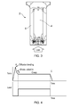
- FIG. 4 An illustration of the heating/cooling and loading cycle applied to the rotor disc 2 is shown in Figure 4 .
- the rotor disc 2 is heated relatively rapidly to the diffusion bonding temperature at point A, then allowed to cool.
- point B cooling is arrested, and the temperature is maintained until point C, after which cooling to ambient temperature is allowed to continue.
- the constant load is applied from point B to point C.
- the load increases the tensile stress in the rotor disc 2 causing the titanium outer section 6 to creep.
- the amount of creep which occurs in the silicon core section 4 is significantly less than the amount of creep which occurs in the titanium outer section 6.
- the amount of creep will increase over time and will be dependent on the temperature at which the load is applied and the magnitude of the applied load. It will therefore be appreciated that a higher temperature and/or an increased applied load will shorten the time required to achieve a desired amount of creep.
- the desired amount of creep will depend on the target design life of the rotor disc and the duty cycle the rotor disc will experience in use.
- the load is removed from the plunger 14 and the rotor disc 2 is allowed to cool below the predetermined temperature to a cold condition, for example to the ambient temperature.
- the creep strain introduced during loading is locked into the outer section 6 during this further cooling process. Consequently, the tensile stress which is ordinarily generated in the outer section 6 when the rotor disc 2 is cooled below the predetermined temperature is offset by the locked-in creep strain. The effect of the locked-in creep strain is thus to reduce the tensile stress in the outer section 6 in the cold condition.
- the amount of creep is dependent on the material type and creep process parameters.
- a particular type of material will have its own creep characteristics.
- the creep process parameters include the temperature of the material, the stress level in the material and the duration of the creep process. Consequently, the desired amount of creep for a particular material can be generated by careful optimisation of all the creep process parameters.
- Figure 7 shows the rotor disc 2 carried by a carrier 24 for loading the rotor disc 2.
- the carrier comprises circular plates 26, 28 between which the rotor disc 2 is clamped.
- the plates 26, 28 are mounted to a rotary shaft 30.
- the rotor disc 2 is loaded by rotating the carrier 24, and hence the rotor disc 2, at not less than 8000 rpm.
- the centrifugal forces acting on the rotor disc 2 load the outer section 6 of the rotor disc 2 so that when the rotor disc 2 is held at the predetermined temperature for the predetermined period of time (described previously) creep occurs in the outer section 6. It will be appreciated that the stress generated within the spinning rotor disc 2 will depend on the rotational speed and geometry of the rotor disc 2.
- a large fan disc may be spun at 3000 rpm whereas a small high pressure compressor disc (e.g. for a helicopter engine) may be spun at 25000 rpm.
- the tensile stress distribution in the outer section 6 generated by spinning the rotor disc 2 replicates the stresses in the rotor disc 2 during operation. Dissipation of the tensile stresses by allowing the rotor disc 2 to creep whilst being spun before the rotor disc 2 is allowed to cool will thus create a locked-in creep strain which is particularly effective at alleviating the tensile stresses in the rotor disc 2 during subsequent operation.
- the above methods are described as being performed by arresting the cooling process following diffusion bonding, the methods may also be performed on a pre-bonded rotor disc by heating the rotor disc to the predetermined temperature and maintaining the rotor disc at the predetermined temperature while the rotor disc is loaded.
- optimum treatment of a rotor disc may be achieved by variation of the load and/or the temperature over time.
- the predetermined period of time does not exceed 100 hours. A predetermined period in excess of this could be used, but this is unlikely owing to the cost of performing a process lasting many days.
Landscapes
- Engineering & Computer Science (AREA)
- Mechanical Engineering (AREA)
- Chemical & Material Sciences (AREA)
- Materials Engineering (AREA)
- Metallurgy (AREA)
- Organic Chemistry (AREA)
- General Engineering & Computer Science (AREA)
- Manufacturing & Machinery (AREA)
- Turbine Rotor Nozzle Sealing (AREA)
- Ceramic Products (AREA)
- Manufacture Of Motors, Generators (AREA)
Applications Claiming Priority (1)
| Application Number | Priority Date | Filing Date | Title |
|---|---|---|---|
| GBGB1005270.2A GB201005270D0 (en) | 2010-03-30 | 2010-03-30 | A method and apparatus for manufacturing a rotor disc |
Publications (3)
| Publication Number | Publication Date |
|---|---|
| EP2374911A2 true EP2374911A2 (de) | 2011-10-12 |
| EP2374911A3 EP2374911A3 (de) | 2017-07-26 |
| EP2374911B1 EP2374911B1 (de) | 2019-05-08 |
Family
ID=42228538
Family Applications (1)
| Application Number | Title | Priority Date | Filing Date |
|---|---|---|---|
| EP11157432.3A Active EP2374911B1 (de) | 2010-03-30 | 2011-03-09 | Verfahren zur Herstellung eines Laufrads |
Country Status (3)
| Country | Link |
|---|---|
| US (1) | US8191755B2 (de) |
| EP (1) | EP2374911B1 (de) |
| GB (1) | GB201005270D0 (de) |
Families Citing this family (4)
| Publication number | Priority date | Publication date | Assignee | Title |
|---|---|---|---|---|
| FR2970266B1 (fr) * | 2011-01-10 | 2013-12-06 | Snecma | Procede de fabrication d'une piece metallique annulaire monobloc a insert de renfort en materiau composite, et piece obtenue |
| US10280768B2 (en) | 2014-11-12 | 2019-05-07 | Rolls-Royce North American Technologies Inc. | Turbine blisk including ceramic matrix composite blades and methods of manufacture |
| US11329585B2 (en) * | 2019-01-25 | 2022-05-10 | General Electric Company | Electric machines with air gap control systems, and systems and methods of controlling an air gap in an electric machine |
| CN110625340A (zh) * | 2019-10-08 | 2019-12-31 | 江西洪都航空工业集团有限责任公司 | 一种ta15钛合金支座类锻件毛坯零件加工工艺 |
Citations (2)
| Publication number | Priority date | Publication date | Assignee | Title |
|---|---|---|---|---|
| EP1527842A1 (de) | 2003-10-24 | 2005-05-04 | ROLLS-ROYCE plc | Verfahren zur Herstellung eines Artikels aus einem faserverstärktem Verbundmetal |
| EP1533393A2 (de) | 2003-11-18 | 2005-05-25 | ROLLS-ROYCE plc | Verfahren zur Herstellung eines Faser- verstärkten Metallmatrixverbundkörpers und Kassette zur Verwendung bei der Herstellung |
Family Cites Families (32)
| Publication number | Priority date | Publication date | Assignee | Title |
|---|---|---|---|---|
| US3571906A (en) * | 1968-09-26 | 1971-03-23 | Caterpillar Tractor Co | Friction bonding of hard-to-grip workpieces |
| US3905723A (en) * | 1972-10-27 | 1975-09-16 | Norton Co | Composite ceramic turbine rotor |
| US4096615A (en) * | 1977-05-31 | 1978-06-27 | General Motors Corporation | Turbine rotor fabrication |
| US4152816A (en) * | 1977-06-06 | 1979-05-08 | General Motors Corporation | Method of manufacturing a hybrid turbine rotor |
| US4247259A (en) * | 1979-04-18 | 1981-01-27 | Avco Corporation | Composite ceramic/metallic turbine blade and method of making same |
| US4270256A (en) * | 1979-06-06 | 1981-06-02 | General Motors Corporation | Manufacture of composite turbine rotors |
| GB2063721A (en) * | 1979-11-23 | 1981-06-10 | Gen Motors Corp | Method of bonding composite turbine wheels |
| GB2109274A (en) * | 1981-11-13 | 1983-06-02 | Rolls Royce | Gas turbine engine rotor assembly |
| US4529452A (en) * | 1984-07-30 | 1985-07-16 | United Technologies Corporation | Process for fabricating multi-alloy components |
| US4867644A (en) * | 1987-05-15 | 1989-09-19 | Allied-Signal Inc. | Composite member, unitary rotor member including same, and method of making |
| US5106012A (en) * | 1989-07-10 | 1992-04-21 | Wyman-Gordon Company | Dual-alloy disk system |
| US5100050A (en) * | 1989-10-04 | 1992-03-31 | General Electric Company | Method of manufacturing dual alloy turbine disks |
| US5161950A (en) * | 1989-10-04 | 1992-11-10 | General Electric Company | Dual alloy turbine disk |
| US5148965A (en) * | 1990-08-09 | 1992-09-22 | Ladish Co., Inc. | Method of shear forge bonding and products produced thereby |
| US5305520A (en) * | 1990-09-01 | 1994-04-26 | Rolls-Royce Plc | Method of making fibre reinforced metal component |
| US5113583A (en) * | 1990-09-14 | 1992-05-19 | United Technologies Corporation | Integrally bladed rotor fabrication |
| FR2715883B1 (fr) * | 1994-02-10 | 1996-03-29 | Snecma | Procédé d'obtention d'une pièce circulaire métallique renforcée par des fibres. |
| US5609471A (en) * | 1995-12-07 | 1997-03-11 | Allison Advanced Development Company, Inc. | Multiproperty rotor disk and method of manufacture |
| US5930332A (en) * | 1996-12-03 | 1999-07-27 | General Electric Company | Method for connecting a molybdenum-based alloy structure to a structure formed from a more ductile alloy, and related articles |
| GB2456637B (en) * | 1997-06-03 | 2010-01-13 | Rolls Royce Plc | A fibre reinforced metal rotor |
| US6061886A (en) * | 1997-07-11 | 2000-05-16 | Honda Giken Kogyo Kabushiki Kaisha | Turbine blade fitting apparatus and fitting method |
| JP4264963B2 (ja) | 1997-08-06 | 2009-05-20 | 株式会社Ihi | 複合構造ディスク製造方法 |
| US6247638B1 (en) * | 1999-04-28 | 2001-06-19 | Allison Advanced Development Company | Selectively reinforced member and method of manufacture |
| ATE322560T1 (de) * | 1999-11-04 | 2006-04-15 | Avio Spa | Verfahren zur herstellung eines bauteiles aus verbundwerkstoff |
| JP2003138352A (ja) * | 2001-10-29 | 2003-05-14 | Mitsubishi Heavy Ind Ltd | 金属基複合材料の成形方法 |
| US6946096B2 (en) | 2002-05-03 | 2005-09-20 | Honeywell International, Inc. | Use of powder metal sintering/diffusion bonding to enable applying silicon carbide or rhenium alloys to face seal rotors |
| GB0327043D0 (en) * | 2003-11-18 | 2004-04-07 | Rolls Royce Plc | A method of manufacturing an article by applying heat and pressure, a method of connecting a pipe to a sealed assembly and a connector for use therein |
| DE102004001260A1 (de) * | 2004-01-08 | 2005-08-04 | Mtu Aero Engines Gmbh | Rotor für eine Turbomaschine und Verfahren zur Herstellung eines solchen Rotors |
| US7950146B2 (en) * | 2007-04-10 | 2011-05-31 | Siemens Energy, Inc. | Co-forged steel rotor component for steam and gas turbine engines |
| US8356980B2 (en) | 2007-10-09 | 2013-01-22 | Hamilton Sundstrand Corporation | Method of manufacturing a turbine rotor |
| US20090304514A1 (en) * | 2007-10-09 | 2009-12-10 | Hamilton Sundstrand Corporation | Method of manufacturing a turbine rotor |
| US8414267B2 (en) * | 2009-09-30 | 2013-04-09 | General Electric Company | Multiple alloy turbine rotor section, welded turbine rotor incorporating the same and methods of their manufacture |
-
2010
- 2010-03-30 GB GBGB1005270.2A patent/GB201005270D0/en not_active Ceased
-
2011
- 2011-03-09 EP EP11157432.3A patent/EP2374911B1/de active Active
- 2011-03-09 US US13/043,840 patent/US8191755B2/en not_active Expired - Fee Related
Patent Citations (2)
| Publication number | Priority date | Publication date | Assignee | Title |
|---|---|---|---|---|
| EP1527842A1 (de) | 2003-10-24 | 2005-05-04 | ROLLS-ROYCE plc | Verfahren zur Herstellung eines Artikels aus einem faserverstärktem Verbundmetal |
| EP1533393A2 (de) | 2003-11-18 | 2005-05-25 | ROLLS-ROYCE plc | Verfahren zur Herstellung eines Faser- verstärkten Metallmatrixverbundkörpers und Kassette zur Verwendung bei der Herstellung |
Also Published As
| Publication number | Publication date |
|---|---|
| US20110240204A1 (en) | 2011-10-06 |
| EP2374911A3 (de) | 2017-07-26 |
| US8191755B2 (en) | 2012-06-05 |
| EP2374911B1 (de) | 2019-05-08 |
| GB201005270D0 (en) | 2010-05-12 |
Similar Documents
| Publication | Publication Date | Title |
|---|---|---|
| JP5856136B2 (ja) | 超合金部品及び合金部品の熱処理方法 | |
| US4536932A (en) | Method for eliminating low cycle fatigue cracking in integrally bladed disks | |
| EP2374911B1 (de) | Verfahren zur Herstellung eines Laufrads | |
| US8839505B2 (en) | Method of manufacturing a magnet assembly | |
| US6234912B1 (en) | High-stiffness composite shaft | |
| EP2926022B1 (de) | Verschachtelte verbundbremstrommel | |
| US20110129347A1 (en) | Process for producing a join to single-crystal or directionally solidified material | |
| EP0352408A1 (de) | Wärmebehandlung für Turbinenräder aus zwei Legierungen | |
| US5305520A (en) | Method of making fibre reinforced metal component | |
| EP2752553B1 (de) | Rotorvorrichtung, turbinenrotorvorrichtung und gasturbine sowie turbinenmotor damit | |
| US5222296A (en) | Method of making a fibre reinforced metal component | |
| US5642851A (en) | Method of producing a circular fibre-reinforced metal article, and apparatus for use in said method | |
| US7557481B2 (en) | Rotor for an electrical machine | |
| EP2096317B1 (de) | Verfahren zur Herstellung der Rotoranordnung einer Rotationsvakuumpumpe | |
| US7617582B2 (en) | Method of manufacturing composite generator rotor shaft | |
| CN111745280A (zh) | 在摩擦焊接期间减少应力和变形的系统和方法 | |
| US20100158676A1 (en) | Composite component | |
| JP6899910B2 (ja) | 軸流タービン | |
| US20070274832A1 (en) | Rotor For A Turbo Machine And Method For The Manufacture Of Such A Rotor | |
| EP3290133B1 (de) | Herstellungsverfahren einer abriebdichtung für strömungsmaschine | |
| CN117245340B (zh) | 一种Ti2AlNb/TC4双合金盘的制备方法 | |
| US8132325B2 (en) | Co-forged nickel-steel rotor component for steam and gas turbine engines | |
| US11725302B2 (en) | Insert for hot isostatic pressing treatment | |
| US20150158134A1 (en) | Method for producing a turbine rotor of an exhaust gas turbocharger | |
| JP4056269B2 (ja) | 回転真空ポンプの製造方法 |
Legal Events
| Date | Code | Title | Description |
|---|---|---|---|
| PUAI | Public reference made under article 153(3) epc to a published international application that has entered the european phase |
Free format text: ORIGINAL CODE: 0009012 |
|
| AK | Designated contracting states |
Kind code of ref document: A2 Designated state(s): AL AT BE BG CH CY CZ DE DK EE ES FI FR GB GR HR HU IE IS IT LI LT LU LV MC MK MT NL NO PL PT RO RS SE SI SK SM TR |
|
| AX | Request for extension of the european patent |
Extension state: BA ME |
|
| RAP1 | Party data changed (applicant data changed or rights of an application transferred) |
Owner name: ROLLS-ROYCE PLC |
|
| PUAL | Search report despatched |
Free format text: ORIGINAL CODE: 0009013 |
|
| AK | Designated contracting states |
Kind code of ref document: A3 Designated state(s): AL AT BE BG CH CY CZ DE DK EE ES FI FR GB GR HR HU IE IS IT LI LT LU LV MC MK MT NL NO PL PT RO RS SE SI SK SM TR |
|
| AX | Request for extension of the european patent |
Extension state: BA ME |
|
| RIC1 | Information provided on ipc code assigned before grant |
Ipc: F01D 5/28 20060101ALI20170616BHEP Ipc: C22C 47/20 20060101AFI20170616BHEP Ipc: B23P 15/00 20060101ALI20170616BHEP Ipc: F01D 5/02 20060101ALI20170616BHEP Ipc: B22F 5/00 20060101ALI20170616BHEP Ipc: C22C 47/02 20060101ALI20170616BHEP |
|
| STAA | Information on the status of an ep patent application or granted ep patent |
Free format text: STATUS: REQUEST FOR EXAMINATION WAS MADE |
|
| 17P | Request for examination filed |
Effective date: 20180126 |
|
| RBV | Designated contracting states (corrected) |
Designated state(s): AL AT BE BG CH CY CZ DE DK EE ES FI FR GB GR HR HU IE IS IT LI LT LU LV MC MK MT NL NO PL PT RO RS SE SI SK SM TR |
|
| GRAP | Despatch of communication of intention to grant a patent |
Free format text: ORIGINAL CODE: EPIDOSNIGR1 |
|
| STAA | Information on the status of an ep patent application or granted ep patent |
Free format text: STATUS: GRANT OF PATENT IS INTENDED |
|
| GRAS | Grant fee paid |
Free format text: ORIGINAL CODE: EPIDOSNIGR3 |
|
| INTG | Intention to grant announced |
Effective date: 20190110 |
|
| GRAA | (expected) grant |
Free format text: ORIGINAL CODE: 0009210 |
|
| STAA | Information on the status of an ep patent application or granted ep patent |
Free format text: STATUS: THE PATENT HAS BEEN GRANTED |
|
| AK | Designated contracting states |
Kind code of ref document: B1 Designated state(s): AL AT BE BG CH CY CZ DE DK EE ES FI FR GB GR HR HU IE IS IT LI LT LU LV MC MK MT NL NO PL PT RO RS SE SI SK SM TR |
|
| REG | Reference to a national code |
Ref country code: GB Ref legal event code: FG4D |
|
| REG | Reference to a national code |
Ref country code: CH Ref legal event code: EP Ref country code: AT Ref legal event code: REF Ref document number: 1130241 Country of ref document: AT Kind code of ref document: T Effective date: 20190515 |
|
| REG | Reference to a national code |
Ref country code: DE Ref legal event code: R096 Ref document number: 602011058671 Country of ref document: DE Ref country code: IE Ref legal event code: FG4D |
|
| REG | Reference to a national code |
Ref country code: NL Ref legal event code: MP Effective date: 20190508 |
|
| REG | Reference to a national code |
Ref country code: LT Ref legal event code: MG4D |
|
| PG25 | Lapsed in a contracting state [announced via postgrant information from national office to epo] |
Ref country code: FI Free format text: LAPSE BECAUSE OF FAILURE TO SUBMIT A TRANSLATION OF THE DESCRIPTION OR TO PAY THE FEE WITHIN THE PRESCRIBED TIME-LIMIT Effective date: 20190508 Ref country code: NO Free format text: LAPSE BECAUSE OF FAILURE TO SUBMIT A TRANSLATION OF THE DESCRIPTION OR TO PAY THE FEE WITHIN THE PRESCRIBED TIME-LIMIT Effective date: 20190808 Ref country code: LT Free format text: LAPSE BECAUSE OF FAILURE TO SUBMIT A TRANSLATION OF THE DESCRIPTION OR TO PAY THE FEE WITHIN THE PRESCRIBED TIME-LIMIT Effective date: 20190508 Ref country code: NL Free format text: LAPSE BECAUSE OF FAILURE TO SUBMIT A TRANSLATION OF THE DESCRIPTION OR TO PAY THE FEE WITHIN THE PRESCRIBED TIME-LIMIT Effective date: 20190508 Ref country code: ES Free format text: LAPSE BECAUSE OF FAILURE TO SUBMIT A TRANSLATION OF THE DESCRIPTION OR TO PAY THE FEE WITHIN THE PRESCRIBED TIME-LIMIT Effective date: 20190508 Ref country code: HR Free format text: LAPSE BECAUSE OF FAILURE TO SUBMIT A TRANSLATION OF THE DESCRIPTION OR TO PAY THE FEE WITHIN THE PRESCRIBED TIME-LIMIT Effective date: 20190508 Ref country code: AL Free format text: LAPSE BECAUSE OF FAILURE TO SUBMIT A TRANSLATION OF THE DESCRIPTION OR TO PAY THE FEE WITHIN THE PRESCRIBED TIME-LIMIT Effective date: 20190508 Ref country code: PT Free format text: LAPSE BECAUSE OF FAILURE TO SUBMIT A TRANSLATION OF THE DESCRIPTION OR TO PAY THE FEE WITHIN THE PRESCRIBED TIME-LIMIT Effective date: 20190908 Ref country code: SE Free format text: LAPSE BECAUSE OF FAILURE TO SUBMIT A TRANSLATION OF THE DESCRIPTION OR TO PAY THE FEE WITHIN THE PRESCRIBED TIME-LIMIT Effective date: 20190508 |
|
| PG25 | Lapsed in a contracting state [announced via postgrant information from national office to epo] |
Ref country code: LV Free format text: LAPSE BECAUSE OF FAILURE TO SUBMIT A TRANSLATION OF THE DESCRIPTION OR TO PAY THE FEE WITHIN THE PRESCRIBED TIME-LIMIT Effective date: 20190508 Ref country code: GR Free format text: LAPSE BECAUSE OF FAILURE TO SUBMIT A TRANSLATION OF THE DESCRIPTION OR TO PAY THE FEE WITHIN THE PRESCRIBED TIME-LIMIT Effective date: 20190809 Ref country code: RS Free format text: LAPSE BECAUSE OF FAILURE TO SUBMIT A TRANSLATION OF THE DESCRIPTION OR TO PAY THE FEE WITHIN THE PRESCRIBED TIME-LIMIT Effective date: 20190508 Ref country code: BG Free format text: LAPSE BECAUSE OF FAILURE TO SUBMIT A TRANSLATION OF THE DESCRIPTION OR TO PAY THE FEE WITHIN THE PRESCRIBED TIME-LIMIT Effective date: 20190808 |
|
| REG | Reference to a national code |
Ref country code: AT Ref legal event code: MK05 Ref document number: 1130241 Country of ref document: AT Kind code of ref document: T Effective date: 20190508 |
|
| PG25 | Lapsed in a contracting state [announced via postgrant information from national office to epo] |
Ref country code: RO Free format text: LAPSE BECAUSE OF FAILURE TO SUBMIT A TRANSLATION OF THE DESCRIPTION OR TO PAY THE FEE WITHIN THE PRESCRIBED TIME-LIMIT Effective date: 20190508 Ref country code: CZ Free format text: LAPSE BECAUSE OF FAILURE TO SUBMIT A TRANSLATION OF THE DESCRIPTION OR TO PAY THE FEE WITHIN THE PRESCRIBED TIME-LIMIT Effective date: 20190508 Ref country code: SK Free format text: LAPSE BECAUSE OF FAILURE TO SUBMIT A TRANSLATION OF THE DESCRIPTION OR TO PAY THE FEE WITHIN THE PRESCRIBED TIME-LIMIT Effective date: 20190508 Ref country code: AT Free format text: LAPSE BECAUSE OF FAILURE TO SUBMIT A TRANSLATION OF THE DESCRIPTION OR TO PAY THE FEE WITHIN THE PRESCRIBED TIME-LIMIT Effective date: 20190508 Ref country code: EE Free format text: LAPSE BECAUSE OF FAILURE TO SUBMIT A TRANSLATION OF THE DESCRIPTION OR TO PAY THE FEE WITHIN THE PRESCRIBED TIME-LIMIT Effective date: 20190508 Ref country code: DK Free format text: LAPSE BECAUSE OF FAILURE TO SUBMIT A TRANSLATION OF THE DESCRIPTION OR TO PAY THE FEE WITHIN THE PRESCRIBED TIME-LIMIT Effective date: 20190508 |
|
| REG | Reference to a national code |
Ref country code: DE Ref legal event code: R097 Ref document number: 602011058671 Country of ref document: DE |
|
| RAP2 | Party data changed (patent owner data changed or rights of a patent transferred) |
Owner name: ROLLS-ROYCE PLC |
|
| PG25 | Lapsed in a contracting state [announced via postgrant information from national office to epo] |
Ref country code: IT Free format text: LAPSE BECAUSE OF FAILURE TO SUBMIT A TRANSLATION OF THE DESCRIPTION OR TO PAY THE FEE WITHIN THE PRESCRIBED TIME-LIMIT Effective date: 20190508 Ref country code: SM Free format text: LAPSE BECAUSE OF FAILURE TO SUBMIT A TRANSLATION OF THE DESCRIPTION OR TO PAY THE FEE WITHIN THE PRESCRIBED TIME-LIMIT Effective date: 20190508 |
|
| PLBE | No opposition filed within time limit |
Free format text: ORIGINAL CODE: 0009261 |
|
| STAA | Information on the status of an ep patent application or granted ep patent |
Free format text: STATUS: NO OPPOSITION FILED WITHIN TIME LIMIT |
|
| PG25 | Lapsed in a contracting state [announced via postgrant information from national office to epo] |
Ref country code: TR Free format text: LAPSE BECAUSE OF FAILURE TO SUBMIT A TRANSLATION OF THE DESCRIPTION OR TO PAY THE FEE WITHIN THE PRESCRIBED TIME-LIMIT Effective date: 20190508 |
|
| 26N | No opposition filed |
Effective date: 20200211 |
|
| PG25 | Lapsed in a contracting state [announced via postgrant information from national office to epo] |
Ref country code: PL Free format text: LAPSE BECAUSE OF FAILURE TO SUBMIT A TRANSLATION OF THE DESCRIPTION OR TO PAY THE FEE WITHIN THE PRESCRIBED TIME-LIMIT Effective date: 20190508 |
|
| PGFP | Annual fee paid to national office [announced via postgrant information from national office to epo] |
Ref country code: GB Payment date: 20200327 Year of fee payment: 10 Ref country code: DE Payment date: 20200327 Year of fee payment: 10 |
|
| PG25 | Lapsed in a contracting state [announced via postgrant information from national office to epo] |
Ref country code: SI Free format text: LAPSE BECAUSE OF FAILURE TO SUBMIT A TRANSLATION OF THE DESCRIPTION OR TO PAY THE FEE WITHIN THE PRESCRIBED TIME-LIMIT Effective date: 20190508 |
|
| PGFP | Annual fee paid to national office [announced via postgrant information from national office to epo] |
Ref country code: FR Payment date: 20200325 Year of fee payment: 10 |
|
| PG25 | Lapsed in a contracting state [announced via postgrant information from national office to epo] |
Ref country code: MC Free format text: LAPSE BECAUSE OF FAILURE TO SUBMIT A TRANSLATION OF THE DESCRIPTION OR TO PAY THE FEE WITHIN THE PRESCRIBED TIME-LIMIT Effective date: 20190508 |
|
| REG | Reference to a national code |
Ref country code: CH Ref legal event code: PL |
|
| REG | Reference to a national code |
Ref country code: BE Ref legal event code: MM Effective date: 20200331 |
|
| PG25 | Lapsed in a contracting state [announced via postgrant information from national office to epo] |
Ref country code: LU Free format text: LAPSE BECAUSE OF NON-PAYMENT OF DUE FEES Effective date: 20200309 |
|
| PG25 | Lapsed in a contracting state [announced via postgrant information from national office to epo] |
Ref country code: CH Free format text: LAPSE BECAUSE OF NON-PAYMENT OF DUE FEES Effective date: 20200331 Ref country code: LI Free format text: LAPSE BECAUSE OF NON-PAYMENT OF DUE FEES Effective date: 20200331 Ref country code: IE Free format text: LAPSE BECAUSE OF NON-PAYMENT OF DUE FEES Effective date: 20200309 |
|
| PG25 | Lapsed in a contracting state [announced via postgrant information from national office to epo] |
Ref country code: BE Free format text: LAPSE BECAUSE OF NON-PAYMENT OF DUE FEES Effective date: 20200331 |
|
| REG | Reference to a national code |
Ref country code: DE Ref legal event code: R119 Ref document number: 602011058671 Country of ref document: DE |
|
| GBPC | Gb: european patent ceased through non-payment of renewal fee |
Effective date: 20210309 |
|
| PG25 | Lapsed in a contracting state [announced via postgrant information from national office to epo] |
Ref country code: GB Free format text: LAPSE BECAUSE OF NON-PAYMENT OF DUE FEES Effective date: 20210309 Ref country code: FR Free format text: LAPSE BECAUSE OF NON-PAYMENT OF DUE FEES Effective date: 20210331 Ref country code: DE Free format text: LAPSE BECAUSE OF NON-PAYMENT OF DUE FEES Effective date: 20211001 |
|
| PG25 | Lapsed in a contracting state [announced via postgrant information from national office to epo] |
Ref country code: MT Free format text: LAPSE BECAUSE OF FAILURE TO SUBMIT A TRANSLATION OF THE DESCRIPTION OR TO PAY THE FEE WITHIN THE PRESCRIBED TIME-LIMIT Effective date: 20190508 Ref country code: CY Free format text: LAPSE BECAUSE OF FAILURE TO SUBMIT A TRANSLATION OF THE DESCRIPTION OR TO PAY THE FEE WITHIN THE PRESCRIBED TIME-LIMIT Effective date: 20190508 |
|
| PG25 | Lapsed in a contracting state [announced via postgrant information from national office to epo] |
Ref country code: MK Free format text: LAPSE BECAUSE OF FAILURE TO SUBMIT A TRANSLATION OF THE DESCRIPTION OR TO PAY THE FEE WITHIN THE PRESCRIBED TIME-LIMIT Effective date: 20190508 Ref country code: IS Free format text: LAPSE BECAUSE OF FAILURE TO SUBMIT A TRANSLATION OF THE DESCRIPTION OR TO PAY THE FEE WITHIN THE PRESCRIBED TIME-LIMIT Effective date: 20190908 |