EP2374661A1 - Parallel parking assistant system and method thereof - Google Patents
Parallel parking assistant system and method thereof Download PDFInfo
- Publication number
- EP2374661A1 EP2374661A1 EP11159004A EP11159004A EP2374661A1 EP 2374661 A1 EP2374661 A1 EP 2374661A1 EP 11159004 A EP11159004 A EP 11159004A EP 11159004 A EP11159004 A EP 11159004A EP 2374661 A1 EP2374661 A1 EP 2374661A1
- Authority
- EP
- European Patent Office
- Prior art keywords
- vehicle
- distance
- steering system
- command
- commands
- Prior art date
- Legal status (The legal status is an assumption and is not a legal conclusion. Google has not performed a legal analysis and makes no representation as to the accuracy of the status listed.)
- Withdrawn
Links
- 238000000034 method Methods 0.000 title claims abstract description 34
- 238000006073 displacement reaction Methods 0.000 claims description 49
- 230000033001 locomotion Effects 0.000 claims description 11
- 238000004891 communication Methods 0.000 claims description 3
- 238000010586 diagram Methods 0.000 description 8
- 210000003195 fascia Anatomy 0.000 description 2
- 238000005259 measurement Methods 0.000 description 2
- 238000006467 substitution reaction Methods 0.000 description 2
- 230000003116 impacting effect Effects 0.000 description 1
- 238000004519 manufacturing process Methods 0.000 description 1
- 230000000007 visual effect Effects 0.000 description 1
Images


Classifications
-
- B—PERFORMING OPERATIONS; TRANSPORTING
- B62—LAND VEHICLES FOR TRAVELLING OTHERWISE THAN ON RAILS
- B62D—MOTOR VEHICLES; TRAILERS
- B62D15/00—Steering not otherwise provided for
- B62D15/02—Steering position indicators ; Steering position determination; Steering aids
- B62D15/027—Parking aids, e.g. instruction means
-
- B—PERFORMING OPERATIONS; TRANSPORTING
- B62—LAND VEHICLES FOR TRAVELLING OTHERWISE THAN ON RAILS
- B62D—MOTOR VEHICLES; TRAILERS
- B62D15/00—Steering not otherwise provided for
- B62D15/02—Steering position indicators ; Steering position determination; Steering aids
- B62D15/027—Parking aids, e.g. instruction means
- B62D15/028—Guided parking by providing commands to the driver, e.g. acoustically or optically
-
- B—PERFORMING OPERATIONS; TRANSPORTING
- B62—LAND VEHICLES FOR TRAVELLING OTHERWISE THAN ON RAILS
- B62D—MOTOR VEHICLES; TRAILERS
- B62D15/00—Steering not otherwise provided for
- B62D15/02—Steering position indicators ; Steering position determination; Steering aids
- B62D15/027—Parking aids, e.g. instruction means
- B62D15/0285—Parking performed automatically
-
- B—PERFORMING OPERATIONS; TRANSPORTING
- B60—VEHICLES IN GENERAL
- B60R—VEHICLES, VEHICLE FITTINGS, OR VEHICLE PARTS, NOT OTHERWISE PROVIDED FOR
- B60R2300/00—Details of viewing arrangements using cameras and displays, specially adapted for use in a vehicle
- B60R2300/80—Details of viewing arrangements using cameras and displays, specially adapted for use in a vehicle characterised by the intended use of the viewing arrangement
- B60R2300/806—Details of viewing arrangements using cameras and displays, specially adapted for use in a vehicle characterised by the intended use of the viewing arrangement for aiding parking
Definitions
- the present invention generally relates to a parking assistant system and method thereof, and more particularly, a parallel parking assistant system integrated with a vehicle and a method thereof.
- autonomous parallel parking systems require the use of multiple distance sensors that are strategically located at various locations around a host vehicle body structure, such as a front-side fascia, a rear-side fascia, a front bumper, and a rear bumper. These sensors can collectively measure various displacements between the host vehicle and adjacent parked vehicles. The controller can use these various displacement measurements to implement algorithms to adjust a steer angle of the host vehicle to allow the host vehicle to back into the parking space and avoid impacting the adjacent parked vehicles.
- parallel-parking systems can be expensive due to the cost of the multiple sensors and the controller that processes the algorithms.
- the parallel-parking system implementation can require the additional cost of controllable steering (e.g., electric power steering), controllable brakes, and controllable throttles.
- a parallel parking assistant system integrated with a vehicle that includes a steering system, a brake system, and a throttle system.
- the parking assistant system includes a first sensor configured to determine a first distance to an object adjacent to a side of the vehicle, a second sensor configured to determine a second distance between a forward positioned object and a rear positioned object that define a parking space, and a controller in communication with the first and second sensors, wherein the controller is configured to provide commands to control the steering system, the brake system, and the throttle system of the vehicle as a function of the first and second determined distances.
- the commands include a first command configured to command the steering system to be in a clockwise position while the vehicle is moving in a reverse direction for a first reversing distance, a second command configured to command the steering system to be in a substantially straight position while the vehicle is moving in a reverse direction for a second reversing distance, wherein a distance traveled during the first and second reversing distances is a function of a length of the vehicle, and a third command configured to command the steering system to be in a counter-clockwise position while the vehicle is a moving in a reverse direction for a third reversing distance, wherein a distance traveled during the first, second, and third reversing distances is a function of the determined first and second distances, a longitudinal displacement of the vehicle during the first, second, and third commands, and a lateral displacement of the vehicle during the first, second, and third commands.
- the longitudinal and lateral displacement of the vehicle during the first, second, and third commands is a function of a length of a parking space, an offset distance between the vehicle and a forward positioned object, and a width of the vehicle.
- the sensor is at least one of ultrasonic, radar, lidar, and a camera.
- the controller is configured to be all, but only one at a time, in a manual mode, an autonomous mode, and a semi-autonomous mode.
- the controller provides said commands to the steering system, the brake system, and the throttle system, when said controller is in autonomous mode, and provides said commands to a user of the vehicle, who then controls the steering system, the brake system, and the throttle system, based upon said provided commands when said controller (108) is in said manual mode.
- the first sensor is positioned on a rear portion of a passenger side of the vehicle, such that said controller is configured to provide said first command as a function of a lateral displacement between said rear portion of said passenger side of the vehicle and said object adjacent thereto.
- the controller is further configured to provide a command prior to said first command that is configured to command the steering system to be in a substantially straight position while the vehicle is moving in a forward direction from rear positioned adjacent object towards a forward positioned adjacent object.
- the forward positioned adjacent object and a rear positioned adjacent object define a parking space and a longitudinal distance between said forward positioned adjacent object and said rear positioned adjacent object is determined by said second sensor.
- a method of parallel parking a vehicle including a steering system includes the steps of determining a first distance between a side of the vehicle and an object adjacent the side of the vehicle, determining a second distance between a forward positioned object and rear positioned object that define a parking space, rotating the steering system in a clockwise direction while the vehicle is moving in a reverse direction for a first reversing direction, rotating the steering system to a substantially straight position while the vehicle is moving in a reverse direction for a second reversing direction, wherein a distance traveled during the first and second reversing distances is a function of a length of the vehicle, and rotating the steering system to a counter-clockwise direction while the vehicle is moving in a reverse direction for a third reversing direction, wherein a distance traveled during the first, second, and third distances is a function of the determined distance, a longitudinal displacement of the vehicle during the rotating the steering system step, and a lateral displacement of the vehicle during the rotating the rotating the
- the steps of rotating the steering system are configured to be all, but only one at a time, autonomous, semi-autonomous, and manual.
- the manual mode further comprises the step of providing commands to a user of the vehicle who then controls the steering system based upon said provided commands.
- the method further comprises the step of rotating the steering system to be in a substantially straight position, while the vehicle is moving in a forward direction from said rear positioned object towards said forward positioned object.
- the longitudinal and lateral displacement of the vehicle during said first, second, and third commands is a function of a length of a parking space, an offset distance between the vehicle and a forward positioned object, and a width of the vehicle.
- the method further comprises the step of utilizing a substantially equal vehicle backing dynamic motion parameter characteristic when performing both said steps of rotating the steering system in a clockwise direction and rotating the steering system in a counter-clockwise position.
- the method further comprises also the step of determining a lateral distance of a parking space by determining a distance between a forward positioned adjacent object and a rear positioned adjacent object while the vehicle is moving forward, such that said forward positioned adjacent object and said rear positioned adjacent object define a parking space.
- a parallel parking assistant system is generally shown at reference identifier 100.
- the parallel parking assistant system 100 is integrated with a vehicle, which is generally indicated at reference identifier 102 and/or V H , and can include a steering system that is generally indicated at reference identifier 104, a brake system 105, and a throttle system 107.
- the parallel parking assistant system 100 can further include a first sensor 106 that is configured to determine a first distance to an object adjacent to a side of the vehicle 102, V H ( Figs. 3-5 and 7 ), and a second sensor 109 configured to determine a second distance between a forward positioned object and a rear positioned object that define a parking space.
- the parallel parking assistant system 100 can also include a controller 108 in communication with the first sensor 106 and the second sensor 109, wherein the controller 108 is configured to provide commands to the steering system 104, the brake system 105, and the throttle system 107 of the vehicle 102, V H for steering the vehicle 102, V H as a function of the determined first and second distances.
- the commands provided by the controller 108 can include a first command configured to command the steering system 104 to be in a clockwise position while the vehicle 102, V H is moving in a reverse direction for a first reversing distance.
- the commands provided by the controller 108 can further include a second command configured to command the steering system 104 to be in a substantially straight position while the vehicle 102, V H is moving in a reverse direction for a second reversing distance, wherein a distance traveled during the first and second reversing distances is a function of a length of the vehicle (V L ) 102.
- a third command can be configured to command the steering system 104 to be in a counter-clockwise position while the vehicle 102, V H is moving in a reverse direction for a third reversing distance, wherein a distance traveled during the first, second, and third reversing distances is a function of the determined distances, a longitudinal displacement of the vehicle 102, V H during the first, second, and third commands, and a lateral displacement of the vehicle 102, V H during the first, second, and third commands, as set forth in greater detail herein.
- the parallel parking assistant system 100 can use the sensor 106 that is a short-range distance sensor.
- the sensor 106 can be positioned on a passenger side of the vehicle 102, V H , such that the parallel parking assistant system 100 is configured to parallel park the vehicle 102, V H with respect to the passenger side of the vehicle 102, V H as a function of one or more outputs of the sensor 106.
- the sensor 106 can be located on the passenger side of the vehicle 102, V H in order to measure the offset distance X OFFSET ( Fig. 3 ) between the vehicle 102, V H and an adjacent object (e.g., an adjacently parked vehicle V F ).
- the offset distance X OFFSET can be a minimum distance between the vehicle 102, V H and the forward positioned object V F , a maximum distance between the vehicle 102, V H and the rear positioned object V F , or an average distance between the vehicle 102, V H and the forward positioned object V F and the vehicle 102, V H and the rear positioned object V R .
- suitable determined, measured, or calculated distances can be used to determine the offset distance X OFFSET .
- the parallel parking assistant system 100 can then accomplish the parallel parking of the vehicle 102, V H by having three (3) turning sequences while the vehicle 102, V H is moving in a reverse direction, which can allow for both an autonomous, semi-autonomous, or manual mode, as described in greater detail herein.
- the parallel parking assistant system 100 is illustrated and described herein with the sensor 106 being located on a passenger side of the vehicle 102, V H, such that the vehicle 102, V H is parallel parked with respect to the passenger side.
- an additional sensor or the sensor 106 can be located on a driver's side of the vehicle 102, V H , such that the parallel parking assistant system 100 can parallel park the vehicle 102, V H with respect to a driver's side of the vehicle 102, V H .
- the sensor 106, 109 can be at least one of an ultrasonic sensor, a radar sensor, a lidar sensor, a camera, the like, or a combination thereof.
- the controller 108 can be configured to be both, but only one at a time, in an autonomous mode, in a semi-autonomous mode, or in a manual mode according to one embodiment.
- the controller 108 can provide the commands to the steering system 104 when the controller 108 is in the autonomous mode.
- the controller 108 can provide the commands to a user of the vehicle 102, V H, such that the user can control a steering system 104 of the vehicle 102, V H based upon the provided commands.
- the controller 108 can provide the commands by an audio enunciation, a visual output (e.g., one or more indicator lights, an output on a screen, such as, but not limited to, a navigation system screen), the like, or a combination thereof.
- the semi-autonomous mode can incorporate a portion of functions of the autonomous mode and a portion of functions of the manual mode.
- a configuration to switch between the autonomous mode, the semi-autonomous mode, and the manual mode can be configured by a manufacturer of the vehicle 102, V H, a manufacturer of the parallel parking assistant system 100 and/or other components of the vehicle 102, V H, a dealer or seller of the vehicle 102, V H, a user of the vehicle 102, V H , or a combination thereof.
- the steering system 104 can include a steering wheel 110 operably connected to a front axle 112, and the front axle 112 can be operably connected to one or more wheels 114, according to one embodiment.
- the steering wheel 110 is activated or turned in a clockwise direction so that the one or more wheels 114 operably connected to the steering wheel 110 would direct the vehicle 102, V H in a clockwise direction when the vehicle 102, V H is traveling in a forward direction with respect to a normal operational position of the vehicle 102, V H .
- the steering wheel 110 is activated or turned in a substantially straight or counter-clockwise direction, so that the one or more wheels 114 operably connected to the steering wheel 110 would direct the vehicle 102, V H in a substantially straight or counter-clockwise direction when the vehicle 102, V H is traveling in a forward direction with respect to a normal operational position of the vehicle 102, V H , respectively.
- the senor 106 can be positioned on a rear portion of the passenger side of the vehicle 102, V H ( Fig. 1 ), such that the controller 108 can be configured to provide the first, second, and third commands as a function of a lateral displacement between the rear portion of the passenger side of the vehicle 102, V H and one or more objects adjacent thereto (e.g., a forward and rear parked vehicle V F , V R ).
- V H Fig. 1
- the controller 108 can be configured to provide the first, second, and third commands as a function of a lateral displacement between the rear portion of the passenger side of the vehicle 102, V H and one or more objects adjacent thereto (e.g., a forward and rear parked vehicle V F , V R ).
- the controller 108 can also be configured to provide a command prior to the first command, wherein the prior command can be configured to command the steering system 104 to be in a substantially straight position, while the vehicle 102, V H is moving in a forward direction from a rear positioned adjacent object towards a forward positioned adjacent object, such that the forward positioned adjacent object and rear positioned object define a parking space.
- the second sensor 109 can be, but is not limited to, a wheel speed sensor configured to determine the distance between the forward positioned object (e.g., a forward parked vehicle V F ) and the rear positioned object (e.g., a rear parked vehicle V R ).
- the first sensor 106 can be used to measure an offset distance (X OFFSET ) to determine if a parking space exists
- the second sensor 109 can be used to measure a length of a parking space.
- the forward positioned object, the rear positioned object, or a combination thereof can be objects other than vehicles, and that a description herein as to other parked vehicles is for purposes of explanation and not limitation.
- the second sensor 109 can be used to measure the first reversing distance, the second reversing distance, the third reversing distance, the like, or a combination thereof.
- the sensor 106 is located on the passenger side of the vehicle 102, V H , wherein a distance Y S is the distance between a most rear portion of the vehicle 102, V H and the sensor 106 ( Fig. 1 ).
- the vehicle 102 (or host vehicle V H ) length V L can be determined by the distance between an approximate center point of a rear axle 116 to approximately a front bumper 118.
- V H type Fig. 2B
- the vehicle 102, V H length V L can be from an approximate center point of the rear axle 116 to approximately a front corner of the vehicle 102, V H .
- a width of the vehicle 102, V H is represented by X WIDTH
- a displacement between the vehicle 102, V H and a front parked vehicle V F is represented by X OFFSET .
- the displacement value X OFFSET is measured by the sensor 106.
- a longitudinal value Y SPACE of an available parking space which is typically defined by the space between the front parked vehicle V F and a rear parked vehicle V R can be determined.
- the longitudinal value Y SPACE can be measured by a second sensor 109, such as, but not limited to, a wheel speed sensor.
- a total lateral displacement resulting from a completed parallel park maneuver can be represented by X TOTAL
- the total longitudinal displacement resulting from a completed parallel park maneuver can be represented by Y TOTAL
- a total distance traveled by the host vehicle 102, H to complete a parallel park maneuver can be represented by L TOTAL .
- the displacement X OFFSET between the host vehicle 102, V H and a front park vehicle V F can be limited within the bounds of: 0 ⁇ X MIN ⁇ X OFFSET ⁇ X MAX
- variables X MAX and X MIN are selected based upon allowing satisfaction of geometric approximation of turning procedures.
- the variable X MIN can be limited by the distance to an adjacent object (e.g., the front parked vehicle V F ), since the vehicle 102, V H cannot be located in the exact same position as any part of the adjacent objects (e.g., parked vehicle's V F , V R ), and thus, the variable X MIN has a value of greater than zero.
- the variable X OFFSET has a value that is equal to or greater than approximately six inches (6 in), and the variable of X MAX can have a value suitable to ensure the vehicle 102, V H is approximately one driving lane over from the adjacent objects (e.g., parked vehicles V F , V R ).
- the variable X MAX can have any value, but may be limited by other factors, such as, but not limited to, typical dimensions of roadways, a turning radius of the vehicle 102, V H , an error or tolerance of a travel path shape or distance, the like, or a combination hereof.
- the value of the displacement X OFFSET can vary, such that the value of the displacement X OFFSET can be, but is not limited to, a combination of values or an average of values.
- the total longitudinal displacement Y TOTAL for a parallel parking operation can be determined to be able to fit into an allowable parking space as represented by the following equation: Y TOTAL ⁇ Y SPACE
- the first turning backing maneuver is where the steering system 104 is substantially locked in a clockwise direction
- the second turning backing operation can be where the steering system 104 is substantially locked in a counter-clockwise direction.
- the steering system 104 is locked when the steering wheel 110 is turned a maximum position in either direction.
- the first turning backing maneuver in combination with the substantially straight backing maneuver can be configured so that a front end of the vehicle 102, V H does not contact the front parked vehicle V F when the vehicle 102, V H is conducting the second turning backing maneuver, according to one embodiment.
- Various longitudinal displacement values of the vehicle 102, V H during the three (3) steering system 104 turning operation that can be determined are a displacement resulting from a first turning backing maneuver Y T1 , a displacement resulting from the substantially straight backing maneuver Y L , and a displacement resulting from a second turning backing maneuver Y T2 .
- the vehicle 102, V H can have a lateral displacement when utilizing the three (3) steering system 104 turning operation.
- Various lateral displacement values that can be determined include a displacement resulting from first turning backing maneuver X T1 , a displacement resulting from a substantially straight backing maneuver X L , and a displacement resulting from a second turning backing maneuver X T2 .
- exemplary geometry characteristics of a parallel parking maneuver are shown.
- a motion of one or more rear wheels 114 is approximated by a circle when substantially locking the steering system 104 while performing a backing maneuver ( Fig. 6 ).
- front wheels 114 of the vehicle 102, V H typically do not have the same turning radius as rear wheels 114, and the rear axis 116 can point to a center of an imaginary circle, such that a frame of reference is a center point of the rear axle 116 (e.g., a motion traveled).
- Circle characteristics with respect to the rear axle 116 of the vehicle 102, V H can include a radius of an exemplary turning circle R, angle displacement by a turn ⁇ , and a length of arc traveled by the angle displacement L. Typically, for a small angle displacement ⁇ , the circle approximation is nearly correct. This condition can be ensured by satisfaction within geometric bounds of the parallel parking procedure. According to one embodiment, testing can be conducted with the vehicle 102, V H to obtain data and provide table look up values of "R" and "L" variables for various circumstances.
- L T1 R T ⁇ 1 ⁇ ⁇ T ⁇ 1 , (wherein ⁇ T1 is specified in radians)
- L TOTAL L T ⁇ 1 + L L + L T ⁇ 2
- On-board vehicle motion sensors such as, but not limited to, the second sensor 109 (e.g., wheel speed sensors), can provide actual measurements of motions traveled parameters (e.g., L T1 , L L , L T2 ) and approximately translated to a rear axle coordinate frame, according to one embodiment.
- Measured parameters can include a measured distance traveled from a first turning backing maneuver L T1M , a measured distance traveled from a substantially linear backing maneuver L LM , and a measured distance traveled from a second turning back maneuver L T2M .
- opposing circular backing maneuver characteristics can be substantially identical.
- the host vehicle 102, V H can have backing dynamic motion parameter characteristics R, S, and ⁇ that are substantially identical when the steering system 104 is substantially locked in either the clockwise or counter-clockwise position.
- the longitudinal and lateral displacements of the vehicle 102, V H doing the first turning backing maneuver Y T1 , X T1 , and the substantially straight backing maneuver Y L , X L are determined to ensure vehicle's 102, V H front bumper 118 does not contact the front parked vehicles V F rear bumper when performing the second turning backing maneuver ( Fig. 4 ).
- ⁇ T of Equation 24 is solved using numerical analysis techniques.
- the values of X OFFSET , X WIDTH , R T , and L V can be known values because these values are determined using the first sensor 106 and/or the second sensor 109, they are measureable parameters of the vehicle 102, V H, the like, or a combination thereof.
- the parameters set X OFFSET , X WIDTH , R T , and L V are known values, wherein, the values of X OFFSET , X WIDTH , R T , and L V can be known values because these values are determined using the first sensor 106 and/or the second sensor 109, they are measureable parameters of the vehicle 102, V H , the like, or a combination thereof.
- the potential parking space is sufficiently long enough to accommodate the parallel parking maneuver if Equation 28 satisfies Equation 3.
- known vehicle system parameters can include X WIDTH , R T , L V , Y S , X MAX , and X MIN , according to one embodiment.
- V H desires to parallel park, the user can stop the vehicle 102, V H at Position 1 and enable the parallel parking assistant system 100.
- the vehicle 102, V H can then move forward slowly (autonomous or semi-autonomously) past the rear adjacent object (e.g., the rear parked vehicle V R ), and potential parking space, until the sensor 106 detects the forward adjacent object (e.g., the forward parked vehicle V F ).
- the vehicle 102, V H m o tion will stop at Position 2 when the vehicle 102, V H rear bumper is aligned with the forward parked vehicle V F rear bumper.
- the length of the parking space Y SPACE can be measured from a vehicle 102, V H motion sensor (e.g., a wheel speed sensor).
- An offset distance X OFFSET can be measured from the sensor 106, and longitudinal distance Y TOTAL can be calculated from Equation 28.
- the parallel parking assistant system 100 can inform a driver of the vehicle 102, V H whether the potential parking space is suitable for parallel parking operation when the conditions Equations 1 and 2 are met. If the parallel parking space is suitable, the user of the vehicle 102, V H can engage the parallel parking assisting system 100 to allow the vehicle 102, V H to move backwards slowly (autonomously or semi-autonomously) to perform the following three (3) backing maneuvers sequences.
- the first backing steering maneuver can include the steering system 104 being substantially in clockwise locking position.
- Equation 22 L V cos ⁇ T - R T tan ⁇ T
- the vehicle 102, V H can then be positioned between the two parked vehicles V F , V R , or adjacent objects that define the parking space.
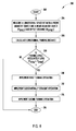
- a method of parallel parking the vehicle 102, V H that includes the steering system 104 is generally shown in Fig. 8 at reference identifier 200.
- the method 200 starts at step 202, and can proceed to step 204, wherein a longitudinal space between a front adjacent object (e.g., a forward positioned object, such as, but not limited to, a front parked vehicle V F ) and a rear adjacent object (e.g., a rear positioned object, such as, but not limited to, a rear parked vehicle V R ) is measured, according to one embodiment.
- the method 200 then proceeds to step 206, wherein a longitudinal parking distance is calculated.
- step 208 it is determined if the parking space is adequately long enough (e.g., Y TOTAL is less than Y SPACE )- If it is determined at decision step 208 that the parking space is not adequately long enough, then the method 200 proceeds to step 216, wherein the method 200 ends. However, if it is determined at decision step 208 that the parking space is adequately long enough, the method 200 proceeds to step 210.
- the first turning operation is implemented. Typically, the first turning operation includes turning the steering system 104 in a counter-clockwise direction, while the vehicle 102, V H travels a first reversing distance.
- a substantially straight operation is implemented, and at step 214, a second turning operation is implemented. Typically, the second turning operation includes turning the steering system 104 in a clockwise direction, while the vehicle 102, V H travels a third reversing distance.
- the method 200 then ends at step 216.
- a method of parallel parking a host vehicle includes the steps of determining a lateral and longitudinal distance of a parking space, determining an offset distance between the host vehicle and an adjacent forward positioned object, implementing a first substantially maximum turning operation while displacing the vehicle a first reversing distance, implementing a substantially straight operation while displacing the vehicle a second reversing distance, and implementing a second substantially maximum turning operation while displacing the vehicle a third reversing distance, wherein the first substantially maximum turning operation and the second substantially maximum turning operation are different directions.
- the parallel parking assistant system 100 and method 200 can be utilized to park a vehicle 102, V H within a parking space defined by two objects, such as two parked vehicles V F , V R , wherein the parallel parking assistant system 100 can be an autonomous mode, a semi-autonomous mode, or a manual mode.
- the parallel parking assistant system 100 provides assistance to a driver of the vehicle 102, V H to parallel park the vehicle 102, V H , while requiring minimal hardware by utilizing a single sensor 106, which can reduce a cost of manufacturing.
- the parallel parking assistant system 100 and method 200 can have additional or alternative advantages.
- the above-described components of the parallel parking assistant system 100 and steps of the method 200 can be combined in additional or alternative ways.
Landscapes
- Engineering & Computer Science (AREA)
- Chemical & Material Sciences (AREA)
- Combustion & Propulsion (AREA)
- Transportation (AREA)
- Mechanical Engineering (AREA)
- Steering Control In Accordance With Driving Conditions (AREA)
- Control Of Driving Devices And Active Controlling Of Vehicle (AREA)
Abstract
A parallel parking assistant system (100) integrated with a vehicle (102, VH) and method (200) thereof are provided, the parking assistant system (100) including a first sensor (106) configured to determine a first distance, a second sensor (109) configured to determine a second distance, and a controller (108) configured to provide commands as a function of the first and second determined distances. The commands include a first command configured to command a steering system (104) to be in a clockwise position while the vehicle (102, VH)is moving in a reverse direction for a first reversing distance, a second command configured to command the steering system (104) to be in a substantially straight position while the vehicle (102, VH) is moving in a reverse direction for a second reversing distance, and a third command configured to command the steering system (104) to be in a counter-clockwise position while the vehicle (102, VH) is a moving in a reverse direction for a third reversing distance.
Description
- The present invention generally relates to a parking assistant system and method thereof, and more particularly, a parallel parking assistant system integrated with a vehicle and a method thereof.
- Generally, autonomous parallel parking systems require the use of multiple distance sensors that are strategically located at various locations around a host vehicle body structure, such as a front-side fascia, a rear-side fascia, a front bumper, and a rear bumper. These sensors can collectively measure various displacements between the host vehicle and adjacent parked vehicles. The controller can use these various displacement measurements to implement algorithms to adjust a steer angle of the host vehicle to allow the host vehicle to back into the parking space and avoid impacting the adjacent parked vehicles.
- These parallel-parking systems can be expensive due to the cost of the multiple sensors and the controller that processes the algorithms. Typically, the parallel-parking system implementation can require the additional cost of controllable steering (e.g., electric power steering), controllable brakes, and controllable throttles.
- According to one aspect of the present invention, a parallel parking assistant system integrated with a vehicle that includes a steering system, a brake system, and a throttle system is provided. The parking assistant system includes a first sensor configured to determine a first distance to an object adjacent to a side of the vehicle, a second sensor configured to determine a second distance between a forward positioned object and a rear positioned object that define a parking space, and a controller in communication with the first and second sensors, wherein the controller is configured to provide commands to control the steering system, the brake system, and the throttle system of the vehicle as a function of the first and second determined distances. The commands include a first command configured to command the steering system to be in a clockwise position while the vehicle is moving in a reverse direction for a first reversing distance, a second command configured to command the steering system to be in a substantially straight position while the vehicle is moving in a reverse direction for a second reversing distance, wherein a distance traveled during the first and second reversing distances is a function of a length of the vehicle, and a third command configured to command the steering system to be in a counter-clockwise position while the vehicle is a moving in a reverse direction for a third reversing distance, wherein a distance traveled during the first, second, and third reversing distances is a function of the determined first and second distances, a longitudinal displacement of the vehicle during the first, second, and third commands, and a lateral displacement of the vehicle during the first, second, and third commands.
- More particularly, in the parallel parking assistant system the longitudinal and lateral displacement of the vehicle during the first, second, and third commands is a function of a length of a parking space, an offset distance between the vehicle and a forward positioned object, and a width of the vehicle. The sensor is at least one of ultrasonic, radar, lidar, and a camera. The controller is configured to be all, but only one at a time, in a manual mode, an autonomous mode, and a semi-autonomous mode. Also, the controller provides said commands to the steering system, the brake system, and the throttle system, when said controller is in autonomous mode, and provides said commands to a user of the vehicle, who then controls the steering system, the brake system, and the throttle system, based upon said provided commands when said controller (108) is in said manual mode. The first sensor is positioned on a rear portion of a passenger side of the vehicle, such that said controller is configured to provide said first command as a function of a lateral displacement between said rear portion of said passenger side of the vehicle and said object adjacent thereto.
- The controller is further configured to provide a command prior to said first command that is configured to command the steering system to be in a substantially straight position while the vehicle is moving in a forward direction from rear positioned adjacent object towards a forward positioned adjacent object. The forward positioned adjacent object and a rear positioned adjacent object define a parking space and a longitudinal distance between said forward positioned adjacent object and said rear positioned adjacent object is determined by said second sensor.
- According to another aspect of the present invention, a method of parallel parking a vehicle including a steering system is provided. The method includes the steps of determining a first distance between a side of the vehicle and an object adjacent the side of the vehicle, determining a second distance between a forward positioned object and rear positioned object that define a parking space, rotating the steering system in a clockwise direction while the vehicle is moving in a reverse direction for a first reversing direction, rotating the steering system to a substantially straight position while the vehicle is moving in a reverse direction for a second reversing direction, wherein a distance traveled during the first and second reversing distances is a function of a length of the vehicle, and rotating the steering system to a counter-clockwise direction while the vehicle is moving in a reverse direction for a third reversing direction, wherein a distance traveled during the first, second, and third distances is a function of the determined distance, a longitudinal displacement of the vehicle during the rotating the steering system step, and a lateral displacement of the vehicle during the rotating the steering system step.
- The steps of rotating the steering system are configured to be all, but only one at a time, autonomous, semi-autonomous, and manual.
- The manual mode further comprises the step of providing commands to a user of the vehicle who then controls the steering system based upon said provided commands.
- The method further comprises the step of rotating the steering system to be in a substantially straight position, while the vehicle is moving in a forward direction from said rear positioned object towards said forward positioned object.
- The longitudinal and lateral displacement of the vehicle during said first, second, and third commands is a function of a length of a parking space, an offset distance between the vehicle and a forward positioned object, and a width of the vehicle.
- The method further comprises the step of utilizing a substantially equal vehicle backing dynamic motion parameter characteristic when performing both said steps of rotating the steering system in a clockwise direction and rotating the steering system in a counter-clockwise position.
- The method further comprises also the step of determining a lateral distance of a parking space by determining a distance between a forward positioned adjacent object and a rear positioned adjacent object while the vehicle is moving forward, such that said forward positioned adjacent object and said rear positioned adjacent object define a parking space.
- These and other features, advantages, and objects of the present invention will be further understood and appreciated by those skilled in the art by reference to the following specification, claims, and appended drawings
- The present invention will now be described, by way of example, with reference to the accompanying drawings, in which:
-
Fig. 1 is a schematic diagram of a parallel parking assistant system integrated with a vehicle, in accordance with one embodiment of the present invention; -
Fig. 2A is a schematic diagram of a vehicle illustrating an exemplary vehicle length VL of a round-front vehicle, in accordance with one embodiment of the present invention; -
Fig. 2B is a schematic diagram of a vehicle illustrating an exemplary vehicle length VL of a flat-front vehicle, in accordance with one embodiment of the present invention; -
Fig. 3 is a schematic diagram illustrating an exemplary path of travel of a vehicle when parallel parking, in accordance with one embodiment of the present invention; -
Fig. 4 is a schematic diagram illustrating an exemplary path of travel of a vehicle when parallel parking, in accordance with one embodiment of the present invention; -
Fig. 5 is a schematic diagram illustrating an exemplary path of travel of a vehicle when parallel parking, in accordance with one embodiment of the present invention; -
Fig. 6 is a schematic diagram illustrating an exemplary path of travel of a vehicle when a steering system of the vehicle is turned to a substantially locked position in a clockwise direction, in accordance with one embodiment of the present invention; -
Fig. 7 is a schematic diagram illustrating an exemplary path of travel of a vehicle when parallel parking, in accordance with one embodiment of the present invention; and -
Fig. 8 is a flowchart illustrating a method of parallel parking a vehicle, in accordance with one embodiment of the present invention. - In regards to
Fig. 1 , a parallel parking assistant system is generally shown atreference identifier 100. Typically, the parallelparking assistant system 100 is integrated with a vehicle, which is generally indicated atreference identifier 102 and/or VH, and can include a steering system that is generally indicated atreference identifier 104, abrake system 105, and athrottle system 107. The parallelparking assistant system 100 can further include afirst sensor 106 that is configured to determine a first distance to an object adjacent to a side of thevehicle 102, VH (Figs. 3-5 and7 ), and asecond sensor 109 configured to determine a second distance between a forward positioned object and a rear positioned object that define a parking space. The parallelparking assistant system 100 can also include a controller 108 in communication with thefirst sensor 106 and thesecond sensor 109, wherein the controller 108 is configured to provide commands to thesteering system 104, thebrake system 105, and thethrottle system 107 of thevehicle 102, VH for steering thevehicle 102, VH as a function of the determined first and second distances. - The commands provided by the controller 108 can include a first command configured to command the
steering system 104 to be in a clockwise position while thevehicle 102, VH is moving in a reverse direction for a first reversing distance. The commands provided by the controller 108 can further include a second command configured to command thesteering system 104 to be in a substantially straight position while thevehicle 102, VH is moving in a reverse direction for a second reversing distance, wherein a distance traveled during the first and second reversing distances is a function of a length of the vehicle (VL) 102. Also, a third command can be configured to command thesteering system 104 to be in a counter-clockwise position while thevehicle 102, VH is moving in a reverse direction for a third reversing distance, wherein a distance traveled during the first, second, and third reversing distances is a function of the determined distances, a longitudinal displacement of thevehicle 102, VH during the first, second, and third commands, and a lateral displacement of thevehicle 102, VH during the first, second, and third commands, as set forth in greater detail herein. - According to one embodiment, the parallel
parking assistant system 100 can use thesensor 106 that is a short-range distance sensor. Thesensor 106 can be positioned on a passenger side of thevehicle 102, VH, such that the parallelparking assistant system 100 is configured to parallel park thevehicle 102, VH with respect to the passenger side of thevehicle 102, VH as a function of one or more outputs of thesensor 106. Typically, thesensor 106 can be located on the passenger side of thevehicle 102, VH in order to measure the offset distance XOFFSET (Fig. 3 ) between thevehicle 102, VH and an adjacent object (e.g., an adjacently parked vehicle VF). According to one embodiment, the offset distance XOFFSET can be a minimum distance between thevehicle 102, VH and the forward positioned object VF, a maximum distance between thevehicle 102, VH and the rear positioned object VF, or an average distance between thevehicle 102, VH and the forward positioned object VF and thevehicle 102, VH and the rear positioned object VR. However, it should be appreciated by those skilled in the art that other suitable determined, measured, or calculated distances can be used to determine the offset distance XOFFSET. The parallelparking assistant system 100 can then accomplish the parallel parking of thevehicle 102, VH by having three (3) turning sequences while thevehicle 102, VH is moving in a reverse direction, which can allow for both an autonomous, semi-autonomous, or manual mode, as described in greater detail herein. - For purposes of explanation and not limitation, the parallel
parking assistant system 100 is illustrated and described herein with thesensor 106 being located on a passenger side of thevehicle 102, VH, such that thevehicle 102, VH is parallel parked with respect to the passenger side. However, it should be appreciated by those skilled in the art that an additional sensor or thesensor 106 can be located on a driver's side of thevehicle 102, VH, such that the parallelparking assistant system 100 can parallel park thevehicle 102, VH with respect to a driver's side of thevehicle 102, VH. By way of explanation and not limitation, thesensor - The controller 108 can be configured to be both, but only one at a time, in an autonomous mode, in a semi-autonomous mode, or in a manual mode according to one embodiment. Typically, the controller 108 can provide the commands to the
steering system 104 when the controller 108 is in the autonomous mode. When the controller 108 is in the manual mode, the controller 108 can provide the commands to a user of thevehicle 102, VH, such that the user can control asteering system 104 of thevehicle 102, VH based upon the provided commands. In such a manual mode, the controller 108 can provide the commands by an audio enunciation, a visual output (e.g., one or more indicator lights, an output on a screen, such as, but not limited to, a navigation system screen), the like, or a combination thereof. The semi-autonomous mode can incorporate a portion of functions of the autonomous mode and a portion of functions of the manual mode. A configuration to switch between the autonomous mode, the semi-autonomous mode, and the manual mode can be configured by a manufacturer of thevehicle 102, VH, a manufacturer of the parallelparking assistant system 100 and/or other components of thevehicle 102, VH, a dealer or seller of thevehicle 102, VH, a user of thevehicle 102, VH, or a combination thereof. - The
steering system 104 can include asteering wheel 110 operably connected to afront axle 112, and thefront axle 112 can be operably connected to one ormore wheels 114, according to one embodiment. Typically, when thesteering system 104 is turned to a clockwise direction, thesteering wheel 110 is activated or turned in a clockwise direction so that the one ormore wheels 114 operably connected to thesteering wheel 110 would direct thevehicle 102, VH in a clockwise direction when thevehicle 102, VH is traveling in a forward direction with respect to a normal operational position of thevehicle 102, VH. Similarly, when thesteering system 104 is turned to a substantially straight or turned to a counter-clockwise direction, thesteering wheel 110 is activated or turned in a substantially straight or counter-clockwise direction, so that the one ormore wheels 114 operably connected to thesteering wheel 110 would direct thevehicle 102, VH in a substantially straight or counter-clockwise direction when thevehicle 102, VH is traveling in a forward direction with respect to a normal operational position of thevehicle 102, VH, respectively. - According to one embodiment, the
sensor 106 can be positioned on a rear portion of the passenger side of thevehicle 102, VH (Fig. 1 ), such that the controller 108 can be configured to provide the first, second, and third commands as a function of a lateral displacement between the rear portion of the passenger side of thevehicle 102, VH and one or more objects adjacent thereto (e.g., a forward and rear parked vehicle VF, VR). The controller 108 can also be configured to provide a command prior to the first command, wherein the prior command can be configured to command thesteering system 104 to be in a substantially straight position, while thevehicle 102, VH is moving in a forward direction from a rear positioned adjacent object towards a forward positioned adjacent object, such that the forward positioned adjacent object and rear positioned object define a parking space. - In such an embodiment, the
second sensor 109 can be, but is not limited to, a wheel speed sensor configured to determine the distance between the forward positioned object (e.g., a forward parked vehicle VF) and the rear positioned object (e.g., a rear parked vehicle VR). Thus, thefirst sensor 106 can be used to measure an offset distance (XOFFSET) to determine if a parking space exists, and thesecond sensor 109 can be used to measure a length of a parking space. However, it should be appreciated by those skilled in the art that the forward positioned object, the rear positioned object, or a combination thereof, can be objects other than vehicles, and that a description herein as to other parked vehicles is for purposes of explanation and not limitation. Additionally or alternatively, thesecond sensor 109 can be used to measure the first reversing distance, the second reversing distance, the third reversing distance, the like, or a combination thereof. - In regards to
Figs. 1-2B , these figures illustrate exemplary dimensions that can be measured or can be known values within the parallelparking assistant system 100. According to one embodiment, thesensor 106 is located on the passenger side of thevehicle 102, VH, wherein a distance YS is the distance between a most rear portion of thevehicle 102, VH and the sensor 106 (Fig. 1 ). With respect toFig. 2A , the vehicle 102 (or host vehicle VH) length VL can be determined by the distance between an approximate center point of arear axle 116 to approximately afront bumper 118. Alternatively, in a flat-front vehicle 102, VH type (Fig. 2B ), thevehicle 102, VH length VL can be from an approximate center point of therear axle 116 to approximately a front corner of thevehicle 102, VH. - In regards to
Fig. 3 , a width of thevehicle 102, VH is represented by XWIDTH, and a displacement between thevehicle 102, VH and a front parked vehicle VF is represented by XOFFSET. Typically, the displacement value XOFFSET is measured by thesensor 106. A longitudinal value YSPACE of an available parking space, which is typically defined by the space between the front parked vehicle VF and a rear parked vehicle VR can be determined. The longitudinal value YSPACE can be measured by asecond sensor 109, such as, but not limited to, a wheel speed sensor. A total lateral displacement resulting from a completed parallel park maneuver can be represented by XTOTAL, while the total longitudinal displacement resulting from a completed parallel park maneuver can be represented by YTOTAL. Also, a total distance traveled by thehost vehicle 102, H to complete a parallel park maneuver can be represented by LTOTAL. - Typically, to conduct a parallel parking procedure, the displacement XOFFSET between the
host vehicle 102, VH and a front park vehicle VF can be limited within the bounds of:
- Typically, variables XMAX and XMIN are selected based upon allowing satisfaction of geometric approximation of turning procedures. The variable XMIN can be limited by the distance to an adjacent object (e.g., the front parked vehicle VF), since the
vehicle 102, VH cannot be located in the exact same position as any part of the adjacent objects (e.g., parked vehicle's VF, VR), and thus, the variable XMIN has a value of greater than zero. According to one embodiment, the variable XOFFSET has a value that is equal to or greater than approximately six inches (6 in), and the variable of XMAX can have a value suitable to ensure thevehicle 102, VH is approximately one driving lane over from the adjacent objects (e.g., parked vehicles VF, VR). However, it should be appreciated by those skilled in the art that the variable XMAX can have any value, but may be limited by other factors, such as, but not limited to, typical dimensions of roadways, a turning radius of thevehicle 102, VH, an error or tolerance of a travel path shape or distance, the like, or a combination hereof. Additionally or alternatively, the value of the displacement XOFFSET can vary, such that the value of the displacement XOFFSET can be, but is not limited to, a combination of values or an average of values. - A total lateral displacement XTOTAL can result in an edge alignment of the
vehicle 102, VH and a front parked vehicle VF, which can be represented by:
- The total longitudinal displacement YTOTAL for a parallel parking operation can be determined to be able to fit into an allowable parking space as represented by the following equation:

- With respect to
Fig. 4 , in an embodiment that is utilizing a three (3)steering system 104 turning operation (e.g., two (2) opposing turning backward maneuvers connected by a substantially straight or linear backing maneuver), various displacement values can be determined. Typically, the first turning backing maneuver is where thesteering system 104 is substantially locked in a clockwise direction, and the linear backing maneuver can be with thesteering system 104 is substantially straight (e.g., θSTEERING=0°). Further, the second turning backing operation can be where thesteering system 104 is substantially locked in a counter-clockwise direction. According to one embodiment, thesteering system 104 is locked when thesteering wheel 110 is turned a maximum position in either direction. - The first turning backing maneuver in combination with the substantially straight backing maneuver can be configured so that a front end of the
vehicle 102, VH does not contact the front parked vehicle VF when thevehicle 102, VH is conducting the second turning backing maneuver, according to one embodiment. Various longitudinal displacement values of thevehicle 102, VH during the three (3)steering system 104 turning operation that can be determined are a displacement resulting from a first turning backing maneuver YT1, a displacement resulting from the substantially straight backing maneuver YL, and a displacement resulting from a second turning backing maneuver YT2. A total longitudinal displacement YTOTAL can be calculated utilizing the following equation:
- Additionally, the
vehicle 102, VH can have a lateral displacement when utilizing the three (3)steering system 104 turning operation. Various lateral displacement values that can be determined include a displacement resulting from first turning backing maneuver XT1, a displacement resulting from a substantially straight backing maneuver XL, and a displacement resulting from a second turning backing maneuver XT2. A total lateral displacement XTOTAL can be calculated utilizing the following equation:
- In regards to
Figs. 5 and6 , exemplary geometry characteristics of a parallel parking maneuver are shown. Typically, a motion of one or morerear wheels 114 is approximated by a circle when substantially locking thesteering system 104 while performing a backing maneuver (Fig. 6 ). However,front wheels 114 of thevehicle 102, VH typically do not have the same turning radius asrear wheels 114, and therear axis 116 can point to a center of an imaginary circle, such that a frame of reference is a center point of the rear axle 116 (e.g., a motion traveled). Circle characteristics with respect to therear axle 116 of thevehicle 102, VH can include a radius of an exemplary turning circle R, angle displacement by a turn θ, and a length of arc traveled by the angle displacement L. Typically, for a small angle displacement θ, the circle approximation is nearly correct. This condition can be ensured by satisfaction within geometric bounds of the parallel parking procedure. According to one embodiment, testing can be conducted with thevehicle 102, VH to obtain data and provide table look up values of "R" and "L" variables for various circumstances. - Longitudinal displacement geometric relationships (
Fig. 5 ) can be calculated by the following equations:


- Lateral displacement geometric relationships (
Fig. 5 ) can be calculated using the following equations:


- The
vehicle 102, VH motion displacement along a circular arc can have various characteristics. A distance traveled from a first turning backing maneuver LT1 can be calculated using the following equation:
(wherein θ T1 is specified in radians) - A distance traveled from a substantially straight backing maneuver LL can be determined. Also, a distance traveled from a second turning backing maneuver LT2 can be calculated by the following equation:

(wherein θ T2 is specified in radians) - Thus, a total distance traveled can be represented by LTOTAL, and calculated by the following equation:

- On-board vehicle motion sensors such as, but not limited to, the second sensor 109 (e.g., wheel speed sensors), can provide actual measurements of motions traveled parameters (e.g., LT1, LL, LT2) and approximately translated to a rear axle coordinate frame, according to one embodiment. Measured parameters can include a measured distance traveled from a first turning backing maneuver LT1M, a measured distance traveled from a substantially linear backing maneuver LLM, and a measured distance traveled from a second turning back maneuver LT2M.
- According to one embodiment, opposing circular backing maneuver characteristics can be substantially identical. In such an embodiment, the
host vehicle 102, VH can have backing dynamic motion parameter characteristics R, S, and θ that are substantially identical when thesteering system 104 is substantially locked in either the clockwise or counter-clockwise position. When assuming the turning characteristics are substantially identical, then the various backing dynamic motion parameter characteristics can be calculated by the following equations: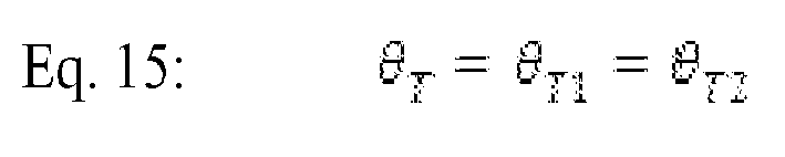


- Substitutions of Equations 15 and 16 into Equations 4-11, and simplification thereof yields:


- According to one embodiment, the longitudinal and lateral displacements of the
vehicle 102, VH doing the first turning backing maneuver YT1, XT1, and the substantially straight backing maneuver YL, XL, are determined to ensure vehicle's 102, VHfront bumper 118 does not contact the front parked vehicles VF rear bumper when performing the second turning backing maneuver (Fig. 4 ). In such an embodiment, a length LV of thevehicle 102, VH can be substantially equal to the combined longitudinal components of the first backing maneuvers yeti and the substantially straight backing maneuver YL, as represented by the following equation:
- Substitution of Equations 6 and 7 with Equations 15 and 16 into Equation 20 yields:

- Solving Equation 21 for LL is represented by the following equation:

- Total linear displacement XTOTAL to accomplish a parallel parking maneuver can be calculated by substituting
Equations 2 and 22 into Equation 19, which yields the following equation:
- Further simplification of Equation 23 yields:

- Solving for a subtended angle displaced by a turn θT from Equation 24, wherein the parameters set (XOFFSET, XWIDTH,RT, LV) are typically known values, yield the following closed-form geometric equation:

- Typically, θT of Equation 24 is solved using numerical analysis techniques. According to one embodiment, the values of XOFFSET, XWIDTH, RT, and LV can be known values because these values are determined using the
first sensor 106 and/or thesecond sensor 109, they are measureable parameters of thevehicle 102, VH, the like, or a combination thereof. - Total longitudinal displacement YTOTAL required for a parallel parking maneuver can be represented by substituting Equation 22 into Equation 18, which yields the following equation:

- Further simplification of Equation 26 yields the following equation:

- Knowing θT by utilizing Equation 25, then Equation 27 can yield the following closed-form geometric equation:

- Typically, the parameters set XOFFSET, XWIDTH, RT, and LV are known values, wherein, the values of XOFFSET, XWIDTH, RT, and LV can be known values because these values are determined using the
first sensor 106 and/or thesecond sensor 109, they are measureable parameters of thevehicle 102, VH, the like, or a combination thereof. According to one embodiment, the potential parking space is sufficiently long enough to accommodate the parallel parking maneuver if Equation 28 satisfiesEquation 3. - With respect to
Fig. 7 , known vehicle system parameters can include XWIDTH, RT, LV, YS, XMAX, and XMIN, according to one embodiment. When a user of thevehicle 102, VH desires to parallel park, the user can stop thevehicle 102, VH atPosition 1 and enable the parallelparking assistant system 100. Thevehicle 102, VH can then move forward slowly (autonomous or semi-autonomously) past the rear adjacent object (e.g., the rear parked vehicle VR), and potential parking space, until thesensor 106 detects the forward adjacent object (e.g., the forward parked vehicle VF). Thevehicle 102, VH motion will stop atPosition 2 when thevehicle 102, VH rear bumper is aligned with the forward parked vehicle VF rear bumper. The length of the parking space YSPACE can be measured from avehicle 102, VH motion sensor (e.g., a wheel speed sensor). An offset distance XOFFSET can be measured from thesensor 106, and longitudinal distance YTOTAL can be calculated from Equation 28. - The parallel
parking assistant system 100 can inform a driver of thevehicle 102, VH whether the potential parking space is suitable for parallel parking operation when theconditions Equations vehicle 102, VH can engage the parallelparking assisting system 100 to allow thevehicle 102, VH to move backwards slowly (autonomously or semi-autonomously) to perform the following three (3) backing maneuvers sequences. - The first backing steering maneuver can include the
steering system 104 being substantially in clockwise locking position. Thevehicle 102, VH moves backwards until the following transitional conditions are met:
- Using Equation 12 with Equations 15 and 16 yields:

(wherein θT- is translated into radians) - Using Equation 25, Equation 30 then becomes:

- The substantially linear or straight backing maneuver can be when the
steering system 104 is substantially straight (e.g., θSTEERING = 0°), wherein thevehicle 102, VH moves backward until the following transitional conditions are met:
- Using Equation 22 with Equation 32 yields:

- Using Equation 25, then Equation 33 becomes:

- The second backing steering maneuver can be accomplished when the
steering system 104 is substantially locked in a counter-clockwise position, and thevehicle 102, VH moves backwards until the following stopping condition is met:
- Using Equation 12 with Equations 15 and 16 yields:

(wherein θ T , is translated into radians) - Using Equation 25, then Equation 26 becomes:

- The
vehicle 102, VH can then be positioned between the two parked vehicles VF, VR, or adjacent objects that define the parking space. - With respect to
Figs. 1-8 , a method of parallel parking thevehicle 102, VH that includes thesteering system 104 is generally shown inFig. 8 atreference identifier 200. Themethod 200 starts atstep 202, and can proceed to step 204, wherein a longitudinal space between a front adjacent object (e.g., a forward positioned object, such as, but not limited to, a front parked vehicle VF) and a rear adjacent object (e.g., a rear positioned object, such as, but not limited to, a rear parked vehicle VR) is measured, according to one embodiment. Themethod 200 then proceeds to step 206, wherein a longitudinal parking distance is calculated. - At
decision step 208, it is determined if the parking space is adequately long enough (e.g., YTOTAL is less than YSPACE)- If it is determined atdecision step 208 that the parking space is not adequately long enough, then themethod 200 proceeds to step 216, wherein themethod 200 ends. However, if it is determined atdecision step 208 that the parking space is adequately long enough, themethod 200 proceeds to step 210. Atstep 210, the first turning operation is implemented. Typically, the first turning operation includes turning thesteering system 104 in a counter-clockwise direction, while thevehicle 102, VH travels a first reversing distance. At step 212 a substantially straight operation is implemented, and atstep 214, a second turning operation is implemented. Typically, the second turning operation includes turning thesteering system 104 in a clockwise direction, while thevehicle 102, VH travels a third reversing distance. Themethod 200 then ends atstep 216. - According to one aspect of the present invention, a method of parallel parking a host vehicle is provided that includes the steps of determining a lateral and longitudinal distance of a parking space, determining an offset distance between the host vehicle and an adjacent forward positioned object, implementing a first substantially maximum turning operation while displacing the vehicle a first reversing distance, implementing a substantially straight operation while displacing the vehicle a second reversing distance, and implementing a second substantially maximum turning operation while displacing the vehicle a third reversing distance, wherein the first substantially maximum turning operation and the second substantially maximum turning operation are different directions.
- Advantageously, the parallel
parking assistant system 100 andmethod 200 can be utilized to park avehicle 102, VH within a parking space defined by two objects, such as two parked vehicles VF, VR, wherein the parallelparking assistant system 100 can be an autonomous mode, a semi-autonomous mode, or a manual mode. The parallelparking assistant system 100 provides assistance to a driver of thevehicle 102, VH to parallel park thevehicle 102, VH, while requiring minimal hardware by utilizing asingle sensor 106, which can reduce a cost of manufacturing. It should be appreciated by those skilled in the art that the parallelparking assistant system 100 andmethod 200 can have additional or alternative advantages. It should further be appreciated by those skilled in the art that the above-described components of the parallelparking assistant system 100 and steps of themethod 200 can be combined in additional or alternative ways.
Claims (14)
- A parallel parking assistant system (100) integrated with a vehicle (102, VH) that comprises a steering system (104), a brake system (105), and a throttle system (107), said parking assistant system (100) comprising:a first sensor (106) configured to determine a first distance to an object adjacent to a side of the vehicle (102, VH); anda second sensor (109) configured to determine a second distance between a forward positioned object (VF) and a rear positioned object (VR) that define a parking space;a controller (108) in communication with said first and second sensors (106, 109), wherein said controller (108) is configured to provide commands to control the steering system (104) of the vehicle as a function of said determined first and second distances, said provided commands comprise:a first command configured to command the steering system (104) to be in a clockwise position while the vehicle (102, VH) is moving in a reverse direction for a first reversing distance;a second command configured to command the steering system (104) to be in a substantially straight position while the vehicle (102, VH) is moving in a reverse direction for a second reversing distance, wherein a distance traveled during said first and second reversing distances is a function of a length of the vehicle (102, VH); anda third command configured to command the steering system (104) to be in a counter-clockwise position while the vehicle (102, VH) is moving in a reverse direction for a third reversing distance, wherein a distance traveled during said first, second, and third reversing distances is a function of said determined first and second distances, a longitudinal displacement of the vehicle (102, VH) during said first, second, and third commands, and a lateral displacement of the vehicle (102, VH) during said first, second, and third commands.
- The parallel parking assistant system (100) of claim 1, wherein said longitudinal and lateral displacement of the vehicle (102, VH) during said first, second, and third commands is a function of a length of a parking space (YSPACE), an offset distance between the vehicle (102, VH) and a forward positioned object (XOFFSET), and a width of the vehicle (XWIDTH).
- The parallel parking assistant system (100) as set in any of the preceding claim, wherein said sensor is at least one of ultrasonic, radar, lidar, and a camera.
- The parallel parking assistant system (100) as set in any of the preceding claim, wherein said controller (108) is configured to be all, but only one at a time, in a manual mode, an autonomous mode, and a semi-autonomous mode.
- The parallel parking assistant system (100) of claim 4, wherein said controller (108) provides said commands to the steering system (104), the brake system (105), and the throttle system (107), when said controller (108) is in said autonomous mode, and provides said commands to a user of the vehicle (102, VH), who then controls the steering system (104), the brake system (105), and the throttle system (107), based upon said provided commands when said controller (108) is in said manual mode.
- The parallel parking assistant system (100) as set in any of the preceding claim, wherein said first sensor (106) is positioned on a rear portion of a passenger side of the vehicle (102, VH), such that said controller (108) is configured to provide said first command as a function of a lateral displacement between said rear portion of said passenger side of the vehicle (102, VH) and said object adjacent thereto (VF).
- The parallel parking assistant system (100) as set in any of the preceding claim, wherein said controller (108) is further configured to provide a command prior to said first command that is configured to command the steering system (104) to be in a substantially straight position while the vehicle (102, VH) is moving in a forward direction from rear positioned adjacent object (VR) towards a forward positioned adjacent object (VF), such that said forward positioned adjacent object (VF) and a rear positioned adjacent object (VR) define a parking space and a longitudinal distance between said forward positioned adjacent object (VF) and said rear positioned adjacent object (VR) is determined by said second sensor (109).
- A method (200) of parallel parking a vehicle (102, VH) that comprises a steering system (104), said method (200) comprising the steps of:determining a first distance (204) between a side of the vehicle (102, VH) and an object adjacent (VF) said side of the vehicle (102, VH);determining a second distance (204, 206) between a forward positioned object (VF) and a rear positioned object (VR) that define a parking space (YSPACE);rotating the steering system (104) in a clockwise direction while the vehicle (102, VH) is moving in a reverse direction for a first reversing distance (210);rotating the steering system (104) to a substantially straight position while the vehicle (102, VH) is moving in a reverse direction for a second reversing distance (212), wherein a distance traveled during first and second reversing distances is a function of a length of the vehicle (102, VH); androtating the steering system (104) to a counter-clockwise direction while the vehicle (102, VH) is moving in a reverse direction for a third reversing distance (214), wherein a distance traveled during said first, second, and third distances is a function of said determined distance, a longitudinal displacement of the vehicle (102, VH) during said rotating said steering system (104) steps, and a lateral displacement of the vehicle (102, VH) during said rotating said steering system (104) steps.
- The method (200) of claim 8, wherein said steps of rotating the steering system (104) are configured to be all, but only one at a time, autonomous, semi-autonomous, and manual.
- The method (200) of claim 9, when in said manual mode, further comprising the step of:providing commands to a user of the vehicle (102, VH), who then controls the steering system (104) based upon said provided commands.
- The method (200) as set in any of the claim 8 to 10 further comprising the step of:rotating the steering system (104) to be in a substantially straight position, while the vehicle (102, VH) is moving in a forward direction from said rear positioned object (VR) towards said forward positioned object (VF).
- The method (200) as set in any of the claim 8 to 11, wherein said longitudinal and lateral displacement of the vehicle (102, VH) during said first, second, and third commands is a function of a length of a parking space (YSPACE), an offset distance between the vehicle (102, VH) and a forward positioned object (VF) (XOFFSET), and a width of the vehicle (102, VH) (XWIDTH).
- The method (200) as set in any of the claim 8 to 12 further comprising the step of:utilizing a substantially equal vehicle (102, VH) backing dynamic motion parameter characteristic when performing both said steps of rotating the steering system (104) in a clockwise direction and rotating the steering system (104) in a counter-clockwise position.
- The method (200) as set in any of the claim 8 to 13 further comprising the step of:determining a lateral distance of a parking space (YSPACE) by determining a distance between a forward positioned adjacent object (VF) and a rear positioned adjacent object (VR) while the vehicle (102, VH) is moving forward, such that said forward positioned adjacent object (VF) and said rear positioned adjacent object (VR) define a parking space (YSPACE).
Applications Claiming Priority (1)
| Application Number | Priority Date | Filing Date | Title |
|---|---|---|---|
| US12/758,218 US8457844B2 (en) | 2010-04-12 | 2010-04-12 | Parallel parking assistant system and method thereof |
Publications (1)
| Publication Number | Publication Date |
|---|---|
| EP2374661A1 true EP2374661A1 (en) | 2011-10-12 |
Family
ID=44064656
Family Applications (1)
| Application Number | Title | Priority Date | Filing Date |
|---|---|---|---|
| EP11159004A Withdrawn EP2374661A1 (en) | 2010-04-12 | 2011-03-21 | Parallel parking assistant system and method thereof |
Country Status (2)
| Country | Link |
|---|---|
| US (2) | US8457844B2 (en) |
| EP (1) | EP2374661A1 (en) |
Cited By (5)
| Publication number | Priority date | Publication date | Assignee | Title |
|---|---|---|---|---|
| GB2486558A (en) * | 2010-12-14 | 2012-06-20 | Bosch Gmbh Robert | Parking aid which estimates a distance to the curb from vehicle width plus lateral offset to a parked vehicle |
| EP2876025A3 (en) * | 2013-11-08 | 2015-07-08 | Samsung Techwin Co.,Ltd. | Method of generating optimum parking path of unmanned driving vehicle, and unmanned driving vehicle adopting the method |
| US9333908B2 (en) | 2013-11-06 | 2016-05-10 | Frazier Cunningham, III | Parking signaling system |
| EP3078575A1 (en) * | 2015-04-10 | 2016-10-12 | Ford Global Technologies, LLC | Method for automatically parking a vehicle and automatically parking vehicle |
| US10490077B2 (en) | 2015-06-11 | 2019-11-26 | Audi Ag | Method for traffic control in a parking environment |
Families Citing this family (21)
| Publication number | Priority date | Publication date | Assignee | Title |
|---|---|---|---|---|
| US8922498B2 (en) * | 2010-08-06 | 2014-12-30 | Ncr Corporation | Self-service terminal and configurable screen therefor |
| US9581997B1 (en) * | 2011-04-22 | 2017-02-28 | Angel A. Penilla | Method and system for cloud-based communication for automatic driverless movement |
| US10081308B2 (en) * | 2011-07-08 | 2018-09-25 | Bendix Commercial Vehicle Systems Llc | Image-based vehicle detection and distance measuring method and apparatus |
| DE102011112149A1 (en) * | 2011-09-01 | 2013-03-07 | Valeo Schalter Und Sensoren Gmbh | Method for carrying out a parking operation of a vehicle and driver assistance device |
| US9415774B2 (en) * | 2011-09-22 | 2016-08-16 | Nissan Motor Co., Ltd. | Vehicle control apparatus including an obstacle detection device |
| KR101316501B1 (en) * | 2011-10-14 | 2013-10-10 | 현대자동차주식회사 | Parking area detection system and method thereof using mesh space analysis |
| US8838322B1 (en) * | 2012-08-14 | 2014-09-16 | Google Inc. | System to automatically measure perception sensor latency in an autonomous vehicle |
| WO2015120183A1 (en) | 2014-02-05 | 2015-08-13 | Innovative Inventions, LLC | Vehicle lifting and parallel parking aid |
| FR3026638B1 (en) * | 2014-10-07 | 2016-12-16 | Yannick Vaillant | ENVIRONMENTAL ASSEMBLY AND INTERFACE FOR TOUCH STIMULATION OF GUIDANCE ON A TRACK IN THE ENVIRONMENT |
| US9616926B2 (en) * | 2015-01-28 | 2017-04-11 | Hyundai Motor Company | Steering assistance apparatus and method for vehicles |
| DE102015215918A1 (en) * | 2015-08-20 | 2017-02-23 | Continental Teves Ag & Co. Ohg | Parking system with interactive trajectory optimization |
| US10890922B2 (en) * | 2015-11-19 | 2021-01-12 | Agjunction Llc | Automated multi-vehicle alignment steering |
| KR20180136134A (en) * | 2017-06-14 | 2018-12-24 | 주식회사 만도 | Smart parking assist system and method for driving thereof |
| US10262537B1 (en) * | 2018-01-22 | 2019-04-16 | Toyota Jidosha Kabushiki Kaisha | Autonomous optimization of parallel parking space utilization |
| JP7040098B2 (en) * | 2018-02-15 | 2022-03-23 | トヨタ自動車株式会社 | Steering support device |
| DE102018205968A1 (en) * | 2018-04-19 | 2019-10-24 | Volkswagen Aktiengesellschaft | Method for operating a parking assistance system of a motor vehicle and parking assistance system for a motor vehicle |
| CN111506055B (en) * | 2019-01-31 | 2024-03-08 | 苏州科瓴精密机械科技有限公司 | Walking robot and steering control method and control system thereof and walking robot manual work system |
| CN112230657B (en) * | 2020-10-15 | 2024-03-29 | 广州大学 | Intelligent vehicle-oriented regional collaborative driving intention scheduling method, system and medium |
| WO2022144667A1 (en) * | 2020-12-29 | 2022-07-07 | Tata Elxsi Limited | System and method for vehicle navigation |
| US12488687B2 (en) | 2022-08-03 | 2025-12-02 | Qualcomm Incorporated | Filtering V2X sensor data messages |
| US20240046783A1 (en) * | 2022-08-03 | 2024-02-08 | Qualcomm Incorporated | Filtering v2x sensor data messages |
Citations (7)
| Publication number | Priority date | Publication date | Assignee | Title |
|---|---|---|---|---|
| US20020041239A1 (en) * | 2000-07-27 | 2002-04-11 | Yasuo Shimizu | Parking aid system |
| JP2004009791A (en) * | 2002-06-04 | 2004-01-15 | Mitsubishi Motors Corp | Parking assistance device |
| EP1839948A1 (en) * | 2004-12-24 | 2007-10-03 | Matsushita Electric Industrial Co., Ltd. | Driving assistance device |
| EP1908641A1 (en) * | 2005-07-27 | 2008-04-09 | Aisin Seiki Kabushiki Kaisha | Parking assistance device |
| WO2008055567A1 (en) * | 2006-11-08 | 2008-05-15 | Volkswagen Aktiengesellschaft | Parking steering assistant with improved transverse parking function |
| US20090157260A1 (en) * | 2007-12-12 | 2009-06-18 | Hyundai Motor Company | Automatic parking system for vehicle |
| EP2098439A2 (en) * | 2008-03-07 | 2009-09-09 | Robert Bosch Gmbh | Method and device for parking a vehicle in a space using a parking assist |
Family Cites Families (2)
| Publication number | Priority date | Publication date | Assignee | Title |
|---|---|---|---|---|
| DE10256770A1 (en) * | 2002-12-05 | 2004-06-17 | Bayerische Motoren Werke Ag | Method for steering a vehicle to be parked backwards into a parking space |
| US8099214B2 (en) * | 2009-02-09 | 2012-01-17 | GM Global Technology Operations LLC | Path planning for autonomous parking |
-
2010
- 2010-04-12 US US12/758,218 patent/US8457844B2/en active Active
-
2011
- 2011-03-21 EP EP11159004A patent/EP2374661A1/en not_active Withdrawn
-
2013
- 2013-02-07 US US13/761,384 patent/US8489283B2/en active Active
Patent Citations (7)
| Publication number | Priority date | Publication date | Assignee | Title |
|---|---|---|---|---|
| US20020041239A1 (en) * | 2000-07-27 | 2002-04-11 | Yasuo Shimizu | Parking aid system |
| JP2004009791A (en) * | 2002-06-04 | 2004-01-15 | Mitsubishi Motors Corp | Parking assistance device |
| EP1839948A1 (en) * | 2004-12-24 | 2007-10-03 | Matsushita Electric Industrial Co., Ltd. | Driving assistance device |
| EP1908641A1 (en) * | 2005-07-27 | 2008-04-09 | Aisin Seiki Kabushiki Kaisha | Parking assistance device |
| WO2008055567A1 (en) * | 2006-11-08 | 2008-05-15 | Volkswagen Aktiengesellschaft | Parking steering assistant with improved transverse parking function |
| US20090157260A1 (en) * | 2007-12-12 | 2009-06-18 | Hyundai Motor Company | Automatic parking system for vehicle |
| EP2098439A2 (en) * | 2008-03-07 | 2009-09-09 | Robert Bosch Gmbh | Method and device for parking a vehicle in a space using a parking assist |
Cited By (7)
| Publication number | Priority date | Publication date | Assignee | Title |
|---|---|---|---|---|
| GB2486558A (en) * | 2010-12-14 | 2012-06-20 | Bosch Gmbh Robert | Parking aid which estimates a distance to the curb from vehicle width plus lateral offset to a parked vehicle |
| GB2486558B (en) * | 2010-12-14 | 2016-02-24 | Bosch Gmbh Robert | Method and device for supporting a parking operation of a vehicle |
| US9333908B2 (en) | 2013-11-06 | 2016-05-10 | Frazier Cunningham, III | Parking signaling system |
| EP2876025A3 (en) * | 2013-11-08 | 2015-07-08 | Samsung Techwin Co.,Ltd. | Method of generating optimum parking path of unmanned driving vehicle, and unmanned driving vehicle adopting the method |
| US9254870B2 (en) | 2013-11-08 | 2016-02-09 | Hanwha Techwin Co., Ltd. | Method of generating optimum parking path of unmanned driving vehicle, and unmanned driving vehicle adopting the method |
| EP3078575A1 (en) * | 2015-04-10 | 2016-10-12 | Ford Global Technologies, LLC | Method for automatically parking a vehicle and automatically parking vehicle |
| US10490077B2 (en) | 2015-06-11 | 2019-11-26 | Audi Ag | Method for traffic control in a parking environment |
Also Published As
| Publication number | Publication date |
|---|---|
| US8489283B2 (en) | 2013-07-16 |
| US20130151059A1 (en) | 2013-06-13 |
| US8457844B2 (en) | 2013-06-04 |
| US20110251755A1 (en) | 2011-10-13 |
Similar Documents
| Publication | Publication Date | Title |
|---|---|---|
| US8489283B2 (en) | Parallel parking assistant system and method thereof | |
| EP3016835B1 (en) | Vehicle control system | |
| US8098174B2 (en) | Feasible region determination for autonomous parking | |
| EP3016836B1 (en) | Vehicle control system | |
| EP2148220B1 (en) | A motor-vehicle driving assistance system based on radar sensors for detecting the presence of obstacles in an area behind and/or beside the vehicle, particularly for parking assistance | |
| CN101426670B (en) | Parking assistance device and parking assistance method | |
| US8958986B2 (en) | Parking assistance apparatus | |
| EP2988983B1 (en) | System for a towing vehicle | |
| US20130151060A1 (en) | System and method of deriving parking trajectory for vehicle | |
| US10962980B2 (en) | System and methods for reverse braking during automated hitch alignment | |
| US8290657B2 (en) | Direction determination for active park assist | |
| US12036975B2 (en) | Parking a motor vehicle | |
| US20180073891A1 (en) | Odometry method for determining a position of a motor vehicle, control device and motor vehicle | |
| EP1170172A2 (en) | Apparatus for displaying rear view from moving body and method of displaying the rear view | |
| US11180146B2 (en) | Brake control technique to stop a vehicle for assisting automatic trailer hitching | |
| US20210042961A1 (en) | Controller for a vehicle | |
| KR20180100690A (en) | A method of leaving a vehicle from a parking space to a final position with at least semi-autonomous steering of the vehicle, | |
| US11479297B2 (en) | Overshoot protection in hitch assist operation | |
| US11155298B2 (en) | Modified steering angle at completion of hitch assist operation | |
| CN111717116A (en) | System and method for trailer alignment | |
| US11155133B2 (en) | System and methods for vehicle alignment control | |
| JP6906320B2 (en) | Parking support device and parking support control device | |
| US11192552B2 (en) | Vehicle motion control for trailer alignment | |
| US11491833B2 (en) | System and methods for vehicle alignment control | |
| US12434517B2 (en) | Method for assisting during a coupling process with a trailer, computing device, and assistance system for a vehicle |
Legal Events
| Date | Code | Title | Description |
|---|---|---|---|
| PUAI | Public reference made under article 153(3) epc to a published international application that has entered the european phase |
Free format text: ORIGINAL CODE: 0009012 |
|
| AK | Designated contracting states |
Kind code of ref document: A1 Designated state(s): AL AT BE BG CH CY CZ DE DK EE ES FI FR GB GR HR HU IE IS IT LI LT LU LV MC MK MT NL NO PL PT RO RS SE SI SK SM TR |
|
| AX | Request for extension of the european patent |
Extension state: BA ME |
|
| 17P | Request for examination filed |
Effective date: 20120412 |
|
| 17Q | First examination report despatched |
Effective date: 20120509 |
|
| STAA | Information on the status of an ep patent application or granted ep patent |
Free format text: STATUS: THE APPLICATION IS DEEMED TO BE WITHDRAWN |
|
| 18D | Application deemed to be withdrawn |
Effective date: 20120920 |