EP2374650A1 - Device for measuring electric current and voltage on board of electric traction railroad vehicles - Google Patents
Device for measuring electric current and voltage on board of electric traction railroad vehicles Download PDFInfo
- Publication number
- EP2374650A1 EP2374650A1 EP11002562A EP11002562A EP2374650A1 EP 2374650 A1 EP2374650 A1 EP 2374650A1 EP 11002562 A EP11002562 A EP 11002562A EP 11002562 A EP11002562 A EP 11002562A EP 2374650 A1 EP2374650 A1 EP 2374650A1
- Authority
- EP
- European Patent Office
- Prior art keywords
- voltage
- transformer
- current
- electronic circuit
- traction
- Prior art date
- Legal status (The legal status is an assumption and is not a legal conclusion. Google has not performed a legal analysis and makes no representation as to the accuracy of the status listed.)
- Withdrawn
Links
- 238000004804 winding Methods 0.000 claims abstract description 24
- 239000013307 optical fiber Substances 0.000 claims abstract description 9
- 238000003672 processing method Methods 0.000 claims 1
- 239000011810 insulating material Substances 0.000 abstract 2
- 238000005259 measurement Methods 0.000 description 12
- 238000000034 method Methods 0.000 description 6
- 238000012360 testing method Methods 0.000 description 2
- 230000001131 transforming effect Effects 0.000 description 2
- 238000006243 chemical reaction Methods 0.000 description 1
- 230000001143 conditioned effect Effects 0.000 description 1
- 238000010586 diagram Methods 0.000 description 1
- 238000009413 insulation Methods 0.000 description 1
- 239000012212 insulator Substances 0.000 description 1
Images
Classifications
-
- B—PERFORMING OPERATIONS; TRANSPORTING
- B60—VEHICLES IN GENERAL
- B60L—PROPULSION OF ELECTRICALLY-PROPELLED VEHICLES; SUPPLYING ELECTRIC POWER FOR AUXILIARY EQUIPMENT OF ELECTRICALLY-PROPELLED VEHICLES; ELECTRODYNAMIC BRAKE SYSTEMS FOR VEHICLES IN GENERAL; MAGNETIC SUSPENSION OR LEVITATION FOR VEHICLES; MONITORING OPERATING VARIABLES OF ELECTRICALLY-PROPELLED VEHICLES; ELECTRIC SAFETY DEVICES FOR ELECTRICALLY-PROPELLED VEHICLES
- B60L3/00—Electric devices on electrically-propelled vehicles for safety purposes; Monitoring operating variables, e.g. speed, deceleration or energy consumption
- B60L3/12—Recording operating variables ; Monitoring of operating variables
-
- G—PHYSICS
- G01—MEASURING; TESTING
- G01R—MEASURING ELECTRIC VARIABLES; MEASURING MAGNETIC VARIABLES
- G01R15/00—Details of measuring arrangements of the types provided for in groups G01R17/00 - G01R29/00, G01R33/00 - G01R33/26 or G01R35/00
- G01R15/14—Adaptations providing voltage or current isolation, e.g. for high-voltage or high-current networks
- G01R15/142—Arrangements for simultaneous measurements of several parameters employing techniques covered by groups G01R15/14 - G01R15/26
-
- B—PERFORMING OPERATIONS; TRANSPORTING
- B60—VEHICLES IN GENERAL
- B60L—PROPULSION OF ELECTRICALLY-PROPELLED VEHICLES; SUPPLYING ELECTRIC POWER FOR AUXILIARY EQUIPMENT OF ELECTRICALLY-PROPELLED VEHICLES; ELECTRODYNAMIC BRAKE SYSTEMS FOR VEHICLES IN GENERAL; MAGNETIC SUSPENSION OR LEVITATION FOR VEHICLES; MONITORING OPERATING VARIABLES OF ELECTRICALLY-PROPELLED VEHICLES; ELECTRIC SAFETY DEVICES FOR ELECTRICALLY-PROPELLED VEHICLES
- B60L2200/00—Type of vehicles
- B60L2200/26—Rail vehicles
-
- G—PHYSICS
- G01—MEASURING; TESTING
- G01R—MEASURING ELECTRIC VARIABLES; MEASURING MAGNETIC VARIABLES
- G01R15/00—Details of measuring arrangements of the types provided for in groups G01R17/00 - G01R29/00, G01R33/00 - G01R33/26 or G01R35/00
- G01R15/14—Adaptations providing voltage or current isolation, e.g. for high-voltage or high-current networks
- G01R15/18—Adaptations providing voltage or current isolation, e.g. for high-voltage or high-current networks using inductive devices, e.g. transformers
- G01R15/183—Adaptations providing voltage or current isolation, e.g. for high-voltage or high-current networks using inductive devices, e.g. transformers using transformers with a magnetic core
Definitions
- the present invention relates to a device having a double function of measuring line voltage and the current drained by and supplied from a train to allow energy to be metered, while providing a measurement voltage for operating traction drivers.
- the device may be used on board of electric traction railroad vehicles, where the traction driver measurement voltage is fed by a conventional inductively operating transformer, with a 25 kV / 100 V or 15 kV / 100 V ratio or a transforming ratio providing a secondary voltage larger than 10 V and a secondary power of at least 50 VA.
- railroad vehicles are at present power supplied from either an A.C. or D.C.
- the inventive device is applied to, the rated voltage may be of 25 kV at 50 Hz or 15 kV at 16.66 Hz.
- Said vehicles conventionally also comprises the so-called traction drivers, a measurement inlet of which is derived from a transformer arranged on the vehicle roof, the transformer having a power sufficient to operate a plurality of parallel arranged drivers.
- the device according to the present invention synergistically provides both the above functions by a single apparatus housed in an insulating body providing, in addition to target performance, the high voltage insulation necessary to fit safety electric requirements.
- the main object of the present invention is to provide a device suitable to meet all the above regulations and use requirements.
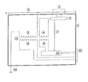
- the inductively operating voltage transformer device is embedded in an insulating body 1 and comprises a primary winding 2 and a secondary winding 4 electrically arranged near the winding 1 and power supplying an electronic card or circuit 5, receiving a measurement signal from a current sensor 3 series coupled to a line wire 6 power supplying the train, said wire 6, therethrough the train drained/supplied current passes, is integrally coupled to the winding 2, thereby the voltage between the wire 6 and ground 10 will be applied to the train, said electronic card or circuit 5 sending information from said sensor 3 through an optical fiber 7 to a second electronic card or circuit 12 receiving the signal from the optical fiber 7 and transforming it into an electric signal to be read by an energy meter, together with the signal taken from the winding 9 and suitably conditioned by the electronic card 12, a secondary winding 8 available on a connector 11 or another dedicated connector to provide the traction driver operating voltage being moreover provided.
- the insulating body 1 of the measurement device for measuring voltage and current on board of railroad vehicles is an insulator assembly including the transformer windings whereas the current sensor 3 may be installed on the top portion of the insulating body 2 together with the electronic card 5 and related connections, as shown in the accompanying drawing.
- the inventive measurement device operates based on an inductively operating transformer 13, including transformer windings 8 and 9, the first of which is used for measuring voltage of the train drivers, the second power supplying an electronic circuit 12 arranged on a bottom portion of the insulating body 1, sending measurements to the power meter.
- the transformer 13 winding 4 is weakly insulated from the primary winding 2, and power supplies the electronic card or circuit 5 for measuring current 3 and transmitting the signal through the optical fiber 7 to the bottom portion of the insulating body 1.
- said transformer 13 winding 4 is arranged near the high voltage portion of the primary winding 2, the latter being connected, at an end thereof, to the high voltage wire 6 and, at the other end thereof, to the vehicle ground or earth 10.
- said transformer 13 operates both at 50 and 16.66 Hz, while assuring the same minimum performance both with respect to the power and the measurement precision.
- the electronic circuit 5, power supplied by the winding 4, receives a signal proportional to the current drained/supplied by the current sensor 3 and performs a digital conversion of the signal, by a known method, while transmitting the converted signal, through the optical fiber 7 to the electronic circuit 12.
- the latter may process the received current signal, to be eventually transformed into an electric analogic signal and, if required, transmit in an electric form the digital signal.
- the electric circuit 12 receives, moreover, the electric line voltage signal, from the winding 9 of the transformer 13 and it may send said signal, if required, directly to the power meter, on board of the train, through the connector 11 or process it, if required, to transform by known methods said signal into a digital signal.
- circuit 12 may also process both the received voltage and current signals to calculate therefrom target parameters, such as power and energy measurement parameters.
- the measurements performed by the electronic circuit 5 and processed by the electronic circuit 12 may be, if required, redundant measurements or two identical circuits, of a type 5 or of a type 12, may be used, for performing the same functions and using two optical fibers 7 to increase the device operating reliability.
Landscapes
- Engineering & Computer Science (AREA)
- Physics & Mathematics (AREA)
- General Physics & Mathematics (AREA)
- Life Sciences & Earth Sciences (AREA)
- Sustainable Development (AREA)
- Sustainable Energy (AREA)
- Power Engineering (AREA)
- Transportation (AREA)
- Mechanical Engineering (AREA)
- Electric Propulsion And Braking For Vehicles (AREA)
- Force Measurement Appropriate To Specific Purposes (AREA)
Abstract
Description
- The present invention relates to a device having a double function of measuring line voltage and the current drained by and supplied from a train to allow energy to be metered, while providing a measurement voltage for operating traction drivers.
- The device may be used on board of electric traction railroad vehicles, where the traction driver measurement voltage is fed by a conventional inductively operating transformer, with a 25 kV / 100 V or 15 kV / 100 V ratio or a transforming ratio providing a secondary voltage larger than 10 V and a secondary power of at least 50 VA.
- As is known, railroad vehicles are at present power supplied from either an A.C. or D.C.
- In A.C. voltage driven vehicles, the inventive device is applied to, the rated voltage may be of 25 kV at 50 Hz or 15 kV at 16.66 Hz.
- Said vehicles conventionally also comprises the so-called traction drivers, a measurement inlet of which is derived from a transformer arranged on the vehicle roof, the transformer having a power sufficient to operate a plurality of parallel arranged drivers.
- In addition to the above requirements, it is also necessary to provide the energy meter with a measurement of the line voltage and train drained/fed current.
- The device according to the present invention synergistically provides both the above functions by a single apparatus housed in an insulating body providing, in addition to target performance, the high voltage insulation necessary to fit safety electric requirements.
- Current European regulations establish performance and features the devices on board of railroad vehicles should have, both with respect to test voltage levels and procedures for testing said devices being used for line voltages up to a rated 25 kV value.
- Accordingly, the main object of the present invention is to provide a device suitable to meet all the above regulations and use requirements.
- The above object, as well as further objects, which will become more apparent hereinafter, are achieved by an electric voltage and current measuring device as herein disclosed.
- Further characteristics and advantages of the inventive device will be more apparent from the following detailed disclosure of a preferred embodiment thereof, as shown in the single drawing figure which is a schematic diagram of the inventive device.
- As shown in the single drawing figure, the inductively operating voltage transformer device is embedded in an
insulating body 1 and comprises aprimary winding 2 and asecondary winding 4 electrically arranged near the winding 1 and power supplying an electronic card orcircuit 5, receiving a measurement signal from acurrent sensor 3 series coupled to aline wire 6 power supplying the train, saidwire 6, therethrough the train drained/supplied current passes, is integrally coupled to thewinding 2, thereby the voltage between thewire 6 andground 10 will be applied to the train, said electronic card orcircuit 5 sending information from saidsensor 3 through anoptical fiber 7 to a second electronic card orcircuit 12 receiving the signal from theoptical fiber 7 and transforming it into an electric signal to be read by an energy meter, together with the signal taken from the winding 9 and suitably conditioned by theelectronic card 12, asecondary winding 8 available on aconnector 11 or another dedicated connector to provide the traction driver operating voltage being moreover provided. - Advantageously, the
insulating body 1 of the measurement device for measuring voltage and current on board of railroad vehicles is an insulator assembly including the transformer windings whereas thecurrent sensor 3 may be installed on the top portion of theinsulating body 2 together with theelectronic card 5 and related connections, as shown in the accompanying drawing. - Further advantageously, the inventive measurement device operates based on an inductively operating
transformer 13, includingtransformer windings 8 and 9, the first of which is used for measuring voltage of the train drivers, the second power supplying anelectronic circuit 12 arranged on a bottom portion of theinsulating body 1, sending measurements to the power meter. - Further advantageously, the
transformer 13 winding 4 is weakly insulated from theprimary winding 2, and power supplies the electronic card orcircuit 5 for measuring current 3 and transmitting the signal through theoptical fiber 7 to the bottom portion of theinsulating body 1. - In particular said
transformer 13winding 4 is arranged near the high voltage portion of theprimary winding 2, the latter being connected, at an end thereof, to thehigh voltage wire 6 and, at the other end thereof, to the vehicle ground orearth 10. - Advantageously, said
transformer 13 operates both at 50 and 16.66 Hz, while assuring the same minimum performance both with respect to the power and the measurement precision. Theelectronic circuit 5, power supplied by thewinding 4, receives a signal proportional to the current drained/supplied by thecurrent sensor 3 and performs a digital conversion of the signal, by a known method, while transmitting the converted signal, through theoptical fiber 7 to theelectronic circuit 12. - The latter, if required, may process the received current signal, to be eventually transformed into an electric analogic signal and, if required, transmit in an electric form the digital signal. The
electric circuit 12 receives, moreover, the electric line voltage signal, from the winding 9 of thetransformer 13 and it may send said signal, if required, directly to the power meter, on board of the train, through theconnector 11 or process it, if required, to transform by known methods said signal into a digital signal. - Finally, the
circuit 12 may also process both the received voltage and current signals to calculate therefrom target parameters, such as power and energy measurement parameters. - All the functions performed by the
circuit 12 are not mutually exclusive ones. - Actually, the measurements performed by the
electronic circuit 5 and processed by theelectronic circuit 12 may be, if required, redundant measurements or two identical circuits, of atype 5 or of atype 12, may be used, for performing the same functions and using twooptical fibers 7 to increase the device operating reliability.
Claims (6)
- A device for measuring electric current and voltage on board of electric traction railroad vehicles, for providing operating voltage to traction drivers and signals to a power meter, characterized in that said device comprises an electric transformer (13) supporting insulating body (1) supporting an electric transformer (13) having a primary winding (2) coupled between a high voltage (6) and a ground (10), and one or more optical fibers (7), wherein a winding (4) power supplies a first high voltage (6) connected electronic circuit (5) receiving a current measuring signal from a current sensor (3) clamped on a head of said insulating body (1), said electronic circuit (5) transmitting the digitally converted current signal through a said optical fiber (7) to a second electronic circuit (12) arranged at a foot portion of said insulating body (1), said electronic circuit (12) receiving a voltage signal from a secondary winding (9) of said transformer (13) and providing an output connector (11) with voltage and current signals, processed by a per se known processing methods, to be used by a power meter on board of said railroad vehicle, a transformer (13) secondary winding (8) providing said output connector (11) with an output voltage for operating said traction drivers.
- A device according to claim 1, characterized in that said transformer (13) provides a same operating performance both at 50 Hz and at 16.66 Hz.
- A device according to claim 1, characterized in that said electronic circuit (5) is supplied by said transformer (13) winding (4), said circuit (5) being so controlled by the signal of said current sensor (3) on said insulating body (1) head as to measure an electric current drained/returned by said railroad vehicle.
- A device according to claim 1, characterized in that said first electronic circuit (5) transmits, through said one or more optical fibers (7), said digitally converted signal to said second electronic circuit (12) arranged at said foot portion of said insulating body (1).
- A device according to claim 3, characterized in that said railroad vehicle drained/returned current is measured by said electronic circuit (5) being coupled to a traction-line high voltage (6).
- A device according to claim 1, characterized in that said transformer (13) comprises a transformer secondary winding (8) providing an output voltage to said traction drivers.
Applications Claiming Priority (1)
| Application Number | Priority Date | Filing Date | Title |
|---|---|---|---|
| ITMI2010A000598A IT1399218B1 (en) | 2010-04-09 | 2010-04-09 | DEVICE FOR TENSION AND CURRENT MEASUREMENT ON BOARD OF ELECTRIC TRACTION RAILWAY VEHICLES |
Publications (1)
| Publication Number | Publication Date |
|---|---|
| EP2374650A1 true EP2374650A1 (en) | 2011-10-12 |
Family
ID=43218152
Family Applications (1)
| Application Number | Title | Priority Date | Filing Date |
|---|---|---|---|
| EP11002562A Withdrawn EP2374650A1 (en) | 2010-04-09 | 2011-03-29 | Device for measuring electric current and voltage on board of electric traction railroad vehicles |
Country Status (2)
| Country | Link |
|---|---|
| EP (1) | EP2374650A1 (en) |
| IT (1) | IT1399218B1 (en) |
Cited By (2)
| Publication number | Priority date | Publication date | Assignee | Title |
|---|---|---|---|---|
| CN103715909A (en) * | 2013-01-16 | 2014-04-09 | 株洲中车轨道交通装备有限公司 | Electric locomotive electronic mutual inductor and application method thereof |
| CN112198383A (en) * | 2020-09-25 | 2021-01-08 | 中铁西安勘察设计研究院有限责任公司 | On-column metering system for railway |
Citations (4)
| Publication number | Priority date | Publication date | Assignee | Title |
|---|---|---|---|---|
| US5530328A (en) * | 1993-12-23 | 1996-06-25 | Pulse Electronics, Inc. | Consist power monitor |
| WO2007104464A2 (en) * | 2006-03-13 | 2007-09-20 | Knorr-Bremse Systeme für Schienenfahrzeuge GmbH | Device for recording and transmitting electrical energy for rail vehicles |
| EP1844970A2 (en) * | 2006-04-12 | 2007-10-17 | Knorr-Bremse Systeme für Schienenfahrzeuge GmbH | Local transport system with remote energy measurement |
| EP2224251A1 (en) * | 2009-02-26 | 2010-09-01 | Tem Elettronica S.r.l. | Device for communicating and measuring voltage and current on board of a rail vehicle with electric drive |
-
2010
- 2010-04-09 IT ITMI2010A000598A patent/IT1399218B1/en active
-
2011
- 2011-03-29 EP EP11002562A patent/EP2374650A1/en not_active Withdrawn
Patent Citations (4)
| Publication number | Priority date | Publication date | Assignee | Title |
|---|---|---|---|---|
| US5530328A (en) * | 1993-12-23 | 1996-06-25 | Pulse Electronics, Inc. | Consist power monitor |
| WO2007104464A2 (en) * | 2006-03-13 | 2007-09-20 | Knorr-Bremse Systeme für Schienenfahrzeuge GmbH | Device for recording and transmitting electrical energy for rail vehicles |
| EP1844970A2 (en) * | 2006-04-12 | 2007-10-17 | Knorr-Bremse Systeme für Schienenfahrzeuge GmbH | Local transport system with remote energy measurement |
| EP2224251A1 (en) * | 2009-02-26 | 2010-09-01 | Tem Elettronica S.r.l. | Device for communicating and measuring voltage and current on board of a rail vehicle with electric drive |
Non-Patent Citations (1)
| Title |
|---|
| TREIGE P ET AL: "Energiemessung auf elektischen Triebfahrzeugen bei der Deutschen Bahn./On-board energy measurment at electric motor vehicles of Deutsche Bahn./", ELEKTRISCHE BAHNEN, OLDENBOURG INDUSTRIEVERLAG, MUNCHEN, DE, vol. 98, no. 8, 1 August 2000 (2000-08-01), pages 300 - 305, XP008083735, ISSN: 0013-5437 * |
Cited By (3)
| Publication number | Priority date | Publication date | Assignee | Title |
|---|---|---|---|---|
| CN103715909A (en) * | 2013-01-16 | 2014-04-09 | 株洲中车轨道交通装备有限公司 | Electric locomotive electronic mutual inductor and application method thereof |
| CN103715909B (en) * | 2013-01-16 | 2016-06-22 | 株洲中车轨道交通装备有限公司 | A kind of electric locomotive electronic mutual inductor and using method thereof |
| CN112198383A (en) * | 2020-09-25 | 2021-01-08 | 中铁西安勘察设计研究院有限责任公司 | On-column metering system for railway |
Also Published As
| Publication number | Publication date |
|---|---|
| ITMI20100598A1 (en) | 2011-10-10 |
| IT1399218B1 (en) | 2013-04-11 |
Similar Documents
| Publication | Publication Date | Title |
|---|---|---|
| US8432175B2 (en) | System and method for evaluating vehicle charging circuits | |
| EP2635910B1 (en) | Partial discharge sensor for a high voltage insulation monitoring device | |
| CN111372809B (en) | Measuring apparatus and method for detecting electrical energy transmitted by charging stations | |
| CN103293372B (en) | Electrical quantity sensor, electrical quantity sensor set up unit and voltameter examining system | |
| US20110298475A1 (en) | Method and device for monitoring a sheath voltage arrester of a cable system | |
| JP5443094B2 (en) | Electric vehicle quick charger charging cable insulation test equipment | |
| CN101837736A (en) | Leakage current detection way and device of electric locomotive power supply system | |
| CN106841815A (en) | A kind of power line steel tower earth resistance In-circiut tester based on voltage drive | |
| KR101333584B1 (en) | Power cable partial discharge measuring equipment having phase reference synchronized to applied voltage | |
| EP2374650A1 (en) | Device for measuring electric current and voltage on board of electric traction railroad vehicles | |
| EP0936469A3 (en) | Loop resistance tester (LRT) for cable shield integrity monitoring | |
| KR100821702B1 (en) | Impedance measuring device of tram line and fault point method | |
| KR100922632B1 (en) | Error discrimination device for transmission and distribution line | |
| CN206906496U (en) | A kind of no-load voltage ratio tester for transformer | |
| US20150244163A1 (en) | Current and voltage module and methods of monitoring current and voltage in power distribution systems | |
| KR102174151B1 (en) | Apparatus for checking the ratio of Current Transformer and Potential Transformer for measurement | |
| CN102096018A (en) | Method for checking welding quality of stator winding joint of large power generator | |
| CN114362097B (en) | High-voltage leakage protection circuit and leakage analysis chip | |
| CN206990679U (en) | A kind of power line steel tower grounding resistance In-circiut tester based on voltage drive | |
| CN113109646B (en) | Power cable identification method and cable identification instrument based on voice | |
| JPH08220162A (en) | Dielectric loss angle measuring device | |
| KR101527942B1 (en) | Device For Measuring A Distance About Grounding Point Of The Control Cable In Railway Substation And Method Therefore | |
| CN208421171U (en) | A kind of Mechanical Failure of HV Circuit Breaker test instrument | |
| JP2623885B2 (en) | Partial discharge detection device for resin mold transformer | |
| KR100517106B1 (en) | Apparatus for measuring electric braking force using catenary voltage and catenary current and method thereof |
Legal Events
| Date | Code | Title | Description |
|---|---|---|---|
| PUAI | Public reference made under article 153(3) epc to a published international application that has entered the european phase |
Free format text: ORIGINAL CODE: 0009012 |
|
| AK | Designated contracting states |
Kind code of ref document: A1 Designated state(s): AL AT BE BG CH CY CZ DE DK EE ES FI FR GB GR HR HU IE IS IT LI LT LU LV MC MK MT NL NO PL PT RO RS SE SI SK SM TR |
|
| AX | Request for extension of the european patent |
Extension state: BA ME |
|
| 17P | Request for examination filed |
Effective date: 20120314 |
|
| GRAP | Despatch of communication of intention to grant a patent |
Free format text: ORIGINAL CODE: EPIDOSNIGR1 |
|
| RIC1 | Information provided on ipc code assigned before grant |
Ipc: B60L 3/12 20060101ALI20160919BHEP Ipc: G01R 15/14 20060101AFI20160919BHEP |
|
| INTG | Intention to grant announced |
Effective date: 20161007 |
|
| STAA | Information on the status of an ep patent application or granted ep patent |
Free format text: STATUS: THE APPLICATION HAS BEEN WITHDRAWN |
|
| 18W | Application withdrawn |
Effective date: 20170208 |