EP2374649A1 - Agricultural driving mechanism and related tool - Google Patents
Agricultural driving mechanism and related tool Download PDFInfo
- Publication number
- EP2374649A1 EP2374649A1 EP11159840A EP11159840A EP2374649A1 EP 2374649 A1 EP2374649 A1 EP 2374649A1 EP 11159840 A EP11159840 A EP 11159840A EP 11159840 A EP11159840 A EP 11159840A EP 2374649 A1 EP2374649 A1 EP 2374649A1
- Authority
- EP
- European Patent Office
- Prior art keywords
- tooth
- tool
- driving mechanism
- shaped protrusions
- drive shaft
- Prior art date
- Legal status (The legal status is an assumption and is not a legal conclusion. Google has not performed a legal analysis and makes no representation as to the accuracy of the status listed.)
- Granted
Links
Images
Classifications
-
- B—PERFORMING OPERATIONS; TRANSPORTING
- B60—VEHICLES IN GENERAL
- B60K—ARRANGEMENT OR MOUNTING OF PROPULSION UNITS OR OF TRANSMISSIONS IN VEHICLES; ARRANGEMENT OR MOUNTING OF PLURAL DIVERSE PRIME-MOVERS IN VEHICLES; AUXILIARY DRIVES FOR VEHICLES; INSTRUMENTATION OR DASHBOARDS FOR VEHICLES; ARRANGEMENTS IN CONNECTION WITH COOLING, AIR INTAKE, GAS EXHAUST OR FUEL SUPPLY OF PROPULSION UNITS IN VEHICLES
- B60K17/00—Arrangement or mounting of transmissions in vehicles
- B60K17/28—Arrangement or mounting of transmissions in vehicles characterised by arrangement, location, or type of power take-off
-
- F—MECHANICAL ENGINEERING; LIGHTING; HEATING; WEAPONS; BLASTING
- F16—ENGINEERING ELEMENTS AND UNITS; GENERAL MEASURES FOR PRODUCING AND MAINTAINING EFFECTIVE FUNCTIONING OF MACHINES OR INSTALLATIONS; THERMAL INSULATION IN GENERAL
- F16D—COUPLINGS FOR TRANSMITTING ROTATION; CLUTCHES; BRAKES
- F16D1/00—Couplings for rigidly connecting two coaxial shafts or other movable machine elements
- F16D1/10—Quick-acting couplings in which the parts are connected by simply bringing them together axially
- F16D1/101—Quick-acting couplings in which the parts are connected by simply bringing them together axially without axial retaining means rotating with the coupling
-
- B—PERFORMING OPERATIONS; TRANSPORTING
- B60—VEHICLES IN GENERAL
- B60Y—INDEXING SCHEME RELATING TO ASPECTS CROSS-CUTTING VEHICLE TECHNOLOGY
- B60Y2200/00—Type of vehicle
- B60Y2200/20—Off-Road Vehicles
- B60Y2200/22—Agricultural vehicles
- B60Y2200/221—Tractors
Definitions
- the present invention refers to an agricultural driving mechanism and to a related tool.
- the present invention refers to the two elements, driving mechanism and tool, which once coupled together make agricultural machines, for example of the single-axle type driven on foot.
- agricultural machines for example of the single-axle type driven on foot.
- such agricultural machines are called tillers or mowers.
- the machine is usually driven on foot through a motorcycle style steering bar, usually known as handlebars, which carries the necessary controls for the various actuations.
- the machine comprises, in succession, the tool, the handlebars, the gearshift, the wheel axle and the motor.
- the machine can foresee for the handlebars to be able to be rotated by 180° so that they are on the side of the motor.
- the machine comprises, in succession, the handlebars, the motor, the gearshift, the wheel axle and the tool.
- the machine can be used with just the tiller, in which case it is a “pure” tiller or just with front tool and, in this case, it is known as a “pure” mower.
- quick-fastening devices can be used, usually through telescopic pipes and locking bolts.
- Agricultural machines known today have some drawbacks concerning the engagement portions of the tools in the power take-offs of the relative driving mechanisms. Indeed, when the two parts are connected so as to constitute the complete operating machine, breaking often occurs due to tangling effects and/or vibrations. In order to avoid such breaking on the market there are joints having high complexity of design capable of reducing the aforementioned instances of breaking. However, since during the operations due to the changing of the tool the coupling is often exposed to dirt and abrasive contaminants, earth and/or other materials typical or agricultural cultivations, such highly complex joints are often unsuitable for quick cleaning and maintenance and therefore are unreliable.
- the purpose of the present invention is to make an agricultural driving mechanism and a related tool capable of solving the aforementioned drawbacks of the prior art in an extremely simple, cost-effective and particularly functional manner.
- Another purpose is to make an agricultural driving mechanism and a related tool in which the relative engagement portions are such as to avoid breaking due to tangling effects and/or vibrations.
- a further purpose is to be able to have an agricultural driving mechanism and a related tool in which the mechanical resistance is divided into equal parts on the machine and on the tool.
- Yet another purpose is to be able to have a agricultural driving mechanism and a related tool in which the relative engagement portions are easy to clean of the dirt and abrasive contaminants, earth and/or other materials typical of agricultural cultivations, and/or in any case able to operate correctly even in the presence of a high degree of contaminating agents.
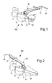
- an agricultural driving mechanism is shown with 10 and a related tool is shown with 10'.
- Reference numeral 100 indicates the machine in which agricultural driving mechanism 10 and related tool 10' are coupled together.
- the tool 10' can be a tiller, as shown in figure 1 , or else a mower, as shown in figure 2 , and in such cases the agricultural machine 100 is respectively called motor tiller or motor mower.
- the agricultural driving mechanism 10 is usually moved by an internal combustion engine 11, running on petrol or on Diesel cycle, in which the power generated is transmitted through a clutch 12 and/or a gearshift 13 to an axle equipped with wheels 14 and to a power take-off 15 that engages the tool 10'.
- the machine 100 is usually driven on foot through a motorcycle style steering bar 16, usually known as "handlebars", which carries the necessary controls 17 for the various actuations.
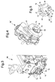
- Figure 3 shows a section view of an agricultural driving mechanism 10 according to the present invention and in particular the power take-off 15, shown enlarged in figure 5 .
- such a power take-off 15 comprises a projecting portion of a drive shaft 18 provided with a plurality of tooth-shaped protrusions 19.
- tooth-shaped protrusions 19 arranged equally spaced apart on the circumference of the drive shaft 18. Analysing the geometry of such tooth-shaped protrusions 19 they comprise V-shaped pointed free ends 20 and widened lower side portions 21 joined with the drive shaft 18.
- tooth-shaped protrusions 19 comprise side profiles 22 23 with variable inclination in which it is possible to identify a first lower portion 22 substantially parallel to the axis of the drive shaft 18 and a second upper portion 23 substantially inclined on both sides with respect to said first portion 22.
- the tool 10' shown schematically in figure 4 at the coupling of the power take-off 15 of the driving mechanism 10, comprises a coupling portion 30 provided with a cavity 31 for receiving the projecting portion of a drive shaft 18 provided with the tooth-shaped protrusions 19 wherein in the cavity 31 the free end of a transmission shaft 33 is housed, in turn provided with a plurality tooth-shaped protrusions 34.
- the tooth-shaped protrusions 34 provided on the transmission shaft 33 are also three in number, equally spaced apart on the circumference of the transmission shaft itself 33.
- the geometry of such tooth-shaped protrusions 34 provided on the transmission shaft 33 is the same as that of the tooth-shaped protrusions 19 of the drive shaft 18, i.e. they comprise V-shaped pointed free ends and widened lower side portions joined with the transmission shaft 33.
- such tooth-shaped protrusions 34 comprise side profiles with variable inclination in which it is possible to identify a first lower portion substantially parallel to the axis of the transmission shaft 33 and a second upper portion substantially inclined on both sides with respect to said first portion.
- the coupling is made up of two similar parts, one positioned on the driving mechanism and the other positioned on the tool, each of which consists of slight tooth shapes.
- an agricultural driving mechanism and a related tool achieves the purposes highlighted earlier.
- the agricultural driving mechanism and the related tool have a coupling such as to avoid breaking due to tangling effects and/or vibrations in which the mechanical resistance is divided into equal parts on the machine and on the tool.
Landscapes
- Engineering & Computer Science (AREA)
- General Engineering & Computer Science (AREA)
- Mechanical Engineering (AREA)
- Chemical & Material Sciences (AREA)
- Combustion & Propulsion (AREA)
- Transportation (AREA)
- Harvester Elements (AREA)
Abstract
Description
- The present invention refers to an agricultural driving mechanism and to a related tool.
- In particular, the present invention refers to the two elements, driving mechanism and tool, which once coupled together make agricultural machines, for example of the single-axle type driven on foot. Depending on the type of tool that is coupled, such agricultural machines are called tillers or mowers.
- In such machines, usually moved by an internal combustion engine running on petrol or on Diesel cycle, the power is transmitted through a clutch and/or a gearshift to an axle equipped with wheels and to a power take-off that engages the tool.
- Indeed, through the power take-off the power flows from the driving mechanism to the tool activating depending on requirements.
- The machine is usually driven on foot through a motorcycle style steering bar, usually known as handlebars, which carries the necessary controls for the various actuations.
- Therefore, the machine comprises, in succession, the tool, the handlebars, the gearshift, the wheel axle and the motor.
- If devised to be polyvalent, the machine can foresee for the handlebars to be able to be rotated by 180° so that they are on the side of the motor.
- In this case the machine comprises, in succession, the handlebars, the motor, the gearshift, the wheel axle and the tool.
- In this way the machine becomes suitable for the use of front tools, like for example sickle mowers, rotary mowers or reel mowers and, in this circumstance, it is often called "reversible mower".
- Sometimes the possibility of rotating the handlebars is unavailable and the machine can be used with just the tiller, in which case it is a "pure" tiller or just with front tool and, in this case, it is known as a "pure" mower.
- One of the biggest advantages linked to the use of these machines is their polyvalence.
- They can indeed be considered to be power units with self-displacement capability that, through the power take-off, are able to actuate a wide range of tools. Normally, the tools are rigidly fixed to the machine through a series of screws.
- In order to make operation quicker and easier, increasing productivity and versatility, quick-fastening devices can be used, usually through telescopic pipes and locking bolts.
- Whatever the solution adopted for the mechanical attachment between the machine and the tool it is necessary for the two parts of the transmission shaft, usually longitudinal, to be able to connect together easily through a joint that allows all of the power to be transmitted reliably from the driving mechanism to the tool.
- Agricultural machines known today have some drawbacks concerning the engagement portions of the tools in the power take-offs of the relative driving mechanisms. Indeed, when the two parts are connected so as to constitute the complete operating machine, breaking often occurs due to tangling effects and/or vibrations. In order to avoid such breaking on the market there are joints having high complexity of design capable of reducing the aforementioned instances of breaking. However, since during the operations due to the changing of the tool the coupling is often exposed to dirt and abrasive contaminants, earth and/or other materials typical or agricultural cultivations, such highly complex joints are often unsuitable for quick cleaning and maintenance and therefore are unreliable. The purpose of the present invention is to make an agricultural driving mechanism and a related tool capable of solving the aforementioned drawbacks of the prior art in an extremely simple, cost-effective and particularly functional manner.
- Another purpose is to make an agricultural driving mechanism and a related tool in which the relative engagement portions are such as to avoid breaking due to tangling effects and/or vibrations.
- A further purpose is to be able to have an agricultural driving mechanism and a related tool in which the mechanical resistance is divided into equal parts on the machine and on the tool.
- Yet another purpose is to be able to have a agricultural driving mechanism and a related tool in which the relative engagement portions are easy to clean of the dirt and abrasive contaminants, earth and/or other materials typical of agricultural cultivations, and/or in any case able to operate correctly even in the presence of a high degree of contaminating agents.
- These purposes according to the present invention are achieved by making an agricultural driving mechanism and a related tool as respectively outlined in claims 1 and 6.
- Further characteristics of the invention are highlighted by the subsequent claims.
- The characteristics and advantages of an agricultural driving mechanism and a related tool according to the present invention will become clearer from the following description, given as an example and not for limiting purposes, referring to the attached schematic drawings, in which:
-
figures 1 and 2 are side elevational views of two example embodiments of agricultural machines according to the present invention provided with different tools; -
figure 3 schematically shows the power take-off foreseen on the agricultural machines according to the present invention; -
figure 4 shows an enlarged detail offigure 3; and figure 5 schematically shows the coupling portion of the tools according to the present invention with the power shown infigure 3 and foreseen in the agricultural machines according to the present invention. - With reference to the figures, an agricultural driving mechanism is shown with 10 and a related tool is shown with 10'.
-
Reference numeral 100 indicates the machine in whichagricultural driving mechanism 10 and related tool 10' are coupled together. - As an example, the tool 10' can be a tiller, as shown in
figure 1 , or else a mower, as shown infigure 2 , and in such cases theagricultural machine 100 is respectively called motor tiller or motor mower. - The
agricultural driving mechanism 10 is usually moved by aninternal combustion engine 11, running on petrol or on Diesel cycle, in which the power generated is transmitted through aclutch 12 and/or agearshift 13 to an axle equipped withwheels 14 and to a power take-off 15 that engages the tool 10'. - Indeed, through the power take-
off 15 the power flows from thedriving mechanism 10 to the tool 10' activating depending on requirements. - The
machine 100 is usually driven on foot through a motorcyclestyle steering bar 16, usually known as "handlebars", which carries thenecessary controls 17 for the various actuations. -
Figure 3 shows a section view of anagricultural driving mechanism 10 according to the present invention and in particular the power take-off 15, shown enlarged infigure 5 . - According to the invention such a power take-
off 15 comprises a projecting portion of adrive shaft 18 provided with a plurality of tooth-shaped protrusions 19. - In the example shown, on the shaft there are three tooth-
shaped protrusions 19 arranged equally spaced apart on the circumference of thedrive shaft 18. Analysing the geometry of such tooth-shaped protrusions 19 they comprise V-shaped pointedfree ends 20 and widenedlower side portions 21 joined with thedrive shaft 18. - Moreover, such tooth-
shaped protrusions 19 compriseside profiles 22 23 with variable inclination in which it is possible to identify a firstlower portion 22 substantially parallel to the axis of thedrive shaft 18 and a secondupper portion 23 substantially inclined on both sides with respect to saidfirst portion 22. - In a totally complementary manner, the tool 10', shown schematically in
figure 4 at the coupling of the power take-off 15 of thedriving mechanism 10, comprises acoupling portion 30 provided with acavity 31 for receiving the projecting portion of adrive shaft 18 provided with the tooth-shaped protrusions 19 wherein in thecavity 31 the free end of atransmission shaft 33 is housed, in turn provided with a plurality tooth-shaped protrusions 34. - In a totally analogous way to the driving mechanism, the tooth-
shaped protrusions 34 provided on thetransmission shaft 33 are also three in number, equally spaced apart on the circumference of the transmission shaft itself 33. - According to the invention, the geometry of such tooth-
shaped protrusions 34 provided on thetransmission shaft 33 is the same as that of the tooth-shaped protrusions 19 of thedrive shaft 18, i.e. they comprise V-shaped pointed free ends and widened lower side portions joined with thetransmission shaft 33. - In accordance with the above, such tooth-
shaped protrusions 34 comprise side profiles with variable inclination in which it is possible to identify a first lower portion substantially parallel to the axis of thetransmission shaft 33 and a second upper portion substantially inclined on both sides with respect to said first portion. - It is absolutely easy to understand how the agricultural driving mechanism and the related tool object of the invention operate.
- The coupling is made up of two similar parts, one positioned on the driving mechanism and the other positioned on the tool, each of which consists of slight tooth shapes.
- In this way, since the division of the coupling circumference takes place in 3 equidistant points both on the drive shaft and on the transmission shaft, when the two parts are connected they constitute a complete operating machine with high mechanical resistance where such mechanical resistance is divided equally both on the driving mechanism and on the tool.
- The presence of wide radii at the bottom of the teeth reduces the risk of breaking due to tangling effects, whereas the pointed shape of the tooth allows the two driving mechanism/tool components to be axially coupled even if the respective teeth and spaces do not perfectly coincide.
- It is absolutely clear how the described solution ensures a high degree of tolerance to contaminating agents, allowing fast and easy cleaning and maintenance of the coupling.
- It has thus been seen that an agricultural driving mechanism and a related tool according to the present invention achieves the purposes highlighted earlier. Indeed, the agricultural driving mechanism and the related tool have a coupling such as to avoid breaking due to tangling effects and/or vibrations in which the mechanical resistance is divided into equal parts on the machine and on the tool.
- Moreover, such a coupling of the present invention is extremely tolerant of contaminating agents typical of agricultural work.
- The agricultural driving mechanism and the related tool of the present invention thus conceived can undergo numerous modifications and variants, all of which are covered by the same inventive concept; moreover, all of the details can be replaced with technically equivalent elements. In practice, the materials used, as well as their sizes, can be whatever according to the technical requirements.
Claims (10)
- Agricultural driving mechanism (10) of the type comprising a motor (11) for delivering power to a power take-off (15) for coupling a tool (10'), characterised in that said power take-off (15) comprises a projecting portion of a drive shaft (18) provided with a plurality of tooth-shaped protrusions (19) for removably coupling with matching protrusions foreseen on said tool (10').
- Driving mechanism (10) according to claim 1, characterised in that it comprises three tooth-shaped protrusions (19) arranged equally spaced apart on the circumference of said drive shaft (18).
- Driving mechanism (10) according to any one of the previous claims characterised in that said tooth-shaped protrusions (19) have V-shaped pointed free ends (20) and widened lower portions (21) joined with said drive shaft (18).
- Driving mechanism (10) according to claim 3, characterised in that said tooth-shaped protrusions (19) comprises side profiles (22, 23) with variable inclination.
- Driving mechanism (10) according to claim 4, characterised in that said side profiles (22, 23) of said tooth-shaped protrusions (19) comprise a first lower portion (22) substantially perpendicular to said end of said drive shaft (18) and a second upper portion (23) substantially inclined by 45° with respect to said first portion (22).
- Tool (10') able to engage on a agricultural driving mechanism according to any one of the previous claims of the type comprising a work implement and a coupling portion (30) with said power take-off (15) of said driving mechanism (10), characterised in that said coupling portion (30) comprises a cavity (31) for receiving the portion of said drive shaft (18) projecting from said power take-off (15) and provided with said tooth-shaped protrusions (19), said cavity (31) housing the free end of a transmission shaft (33) provided with a plurality of tooth-shaped protrusions (34) for removably coupling with said tooth-shaped protrusions (19) foreseen on said drive shaft (18).
- Tool (10') according to claim 6, characterised in that it comprises three tooth-shaped protrusions (34) arranged equally spaced apart on the circumference of said transmission shaft (33).
- Tool (10') according to any one of claims 6 -7 characterised in that said tooth-shaped protrusions (34) have V-shaped pointed free ends and widened lower portions joined with the end of said transmission shaft (33).
- Tool (10') according to claim 8, characterised in that said tooth-shaped protrusions (34) comprise side profiles with variable inclination.
- Tool (10') according to claim 9, characterised in that said side profiles of said tooth-shaped protrusions (34) comprise a first lower portion substantially perpendicular to said end of said drive shaft and a second upper portion substantially inclined by 45° with respect to said first portion.
Applications Claiming Priority (1)
| Application Number | Priority Date | Filing Date | Title |
|---|---|---|---|
| CN201010156328.4A CN102204432B (en) | 2010-03-30 | 2010-03-30 | Agricultural driving device and related tool |
Publications (2)
| Publication Number | Publication Date |
|---|---|
| EP2374649A1 true EP2374649A1 (en) | 2011-10-12 |
| EP2374649B1 EP2374649B1 (en) | 2013-05-22 |
Family
ID=44487074
Family Applications (1)
| Application Number | Title | Priority Date | Filing Date |
|---|---|---|---|
| EP20110159840 Active EP2374649B1 (en) | 2010-03-30 | 2011-03-25 | Agricultural driving mechanism and related tool |
Country Status (3)
| Country | Link |
|---|---|
| EP (1) | EP2374649B1 (en) |
| CN (1) | CN102204432B (en) |
| ES (1) | ES2425209T3 (en) |
Families Citing this family (1)
| Publication number | Priority date | Publication date | Assignee | Title |
|---|---|---|---|---|
| IT202300008787A1 (en) | 2023-05-04 | 2024-11-04 | Bcs Spa | SINGLE-AXLE AGRICULTURAL MACHINE WITH CONTINUOUS SPEED VARIATION AND INDEPENDENT POWER TAKE-OFF |
Citations (7)
| Publication number | Priority date | Publication date | Assignee | Title |
|---|---|---|---|---|
| FR1560109A (en) * | 1967-04-20 | 1969-03-14 | ||
| DE1482841A1 (en) * | 1964-06-26 | 1969-10-16 | Massey Ferguson Ltd | Harvester |
| FR2263675A1 (en) * | 1974-03-16 | 1975-10-10 | Deere & Co | |
| DE3140917A1 (en) * | 1981-10-15 | 1983-06-16 | Armin 7995 Neukirch Waggershauser | Coupling device for accessory units of farm tractors |
| US4892430A (en) * | 1988-11-14 | 1990-01-09 | Durotech Co. | Quick connect-disconnect drive shaft coupling |
| WO2008037006A1 (en) * | 2006-09-26 | 2008-04-03 | Tapp, Margaret, Joan | Machinery hitches |
| CN201388390Y (en) * | 2009-04-23 | 2010-01-27 | 马一楠 | Connecting mechanism of multipurpose gardening machine and gardening machine provided with same |
-
2010
- 2010-03-30 CN CN201010156328.4A patent/CN102204432B/en active Active
-
2011
- 2011-03-25 EP EP20110159840 patent/EP2374649B1/en active Active
- 2011-03-25 ES ES11159840T patent/ES2425209T3/en active Active
Patent Citations (7)
| Publication number | Priority date | Publication date | Assignee | Title |
|---|---|---|---|---|
| DE1482841A1 (en) * | 1964-06-26 | 1969-10-16 | Massey Ferguson Ltd | Harvester |
| FR1560109A (en) * | 1967-04-20 | 1969-03-14 | ||
| FR2263675A1 (en) * | 1974-03-16 | 1975-10-10 | Deere & Co | |
| DE3140917A1 (en) * | 1981-10-15 | 1983-06-16 | Armin 7995 Neukirch Waggershauser | Coupling device for accessory units of farm tractors |
| US4892430A (en) * | 1988-11-14 | 1990-01-09 | Durotech Co. | Quick connect-disconnect drive shaft coupling |
| WO2008037006A1 (en) * | 2006-09-26 | 2008-04-03 | Tapp, Margaret, Joan | Machinery hitches |
| CN201388390Y (en) * | 2009-04-23 | 2010-01-27 | 马一楠 | Connecting mechanism of multipurpose gardening machine and gardening machine provided with same |
Also Published As
| Publication number | Publication date |
|---|---|
| ES2425209T3 (en) | 2013-10-14 |
| EP2374649B1 (en) | 2013-05-22 |
| CN102204432B (en) | 2015-09-09 |
| CN102204432A (en) | 2011-10-05 |
Similar Documents
| Publication | Publication Date | Title |
|---|---|---|
| EP2374649B1 (en) | Agricultural driving mechanism and related tool | |
| JP6186172B2 (en) | Power chainsaw with transfer pump | |
| WO2012116841A1 (en) | Power tool system | |
| JP5672344B2 (en) | Work vehicle | |
| KR200456120Y1 (en) | Vehicle speed proportion type PTO apparatus of tractor | |
| JP6129086B2 (en) | Walking type work machine | |
| CN106907450B (en) | Gearbox for a mechanized agricultural implement and mechanized agricultural implement comprising such a gearbox | |
| JP2014073829A5 (en) | ||
| KR20130044064A (en) | A double-edged revolution is possible the brush cutter knife and knife operating method and knife operating device | |
| JP5910708B2 (en) | Work vehicle | |
| CN101548626B (en) | Gardening cutting tool | |
| JP5168270B2 (en) | Rotary tillage device | |
| KR20130120061A (en) | The bevel gear is applied the brush cutter knife and knife operating method and knife operating device | |
| JP5709420B2 (en) | Mowing machine | |
| JP5488262B2 (en) | Front wheel speed increasing device for work vehicle | |
| CN203362876U (en) | Agriculture transmission shaft joint yoke with overload protection | |
| EP3172952B1 (en) | Walking type tiller | |
| JP7809053B2 (en) | Walk-behind cultivator | |
| JP2006262715A (en) | Walk-type field cultivator | |
| JP2014036583A (en) | Mowing work machine | |
| KR200478688Y1 (en) | attached grinder lawn mower | |
| KR20130058028A (en) | A double-edged revolution is possible the brush cutter knife and knife operating method and knife operating device | |
| EP3791999B1 (en) | Sanding device | |
| RU142230U1 (en) | ROTARY VEHICLE SHAFT EXTENSION WITH WHEEL LOCK FUNCTION | |
| TWM416985U (en) | Agricultural machinery and rotating device thereof |
Legal Events
| Date | Code | Title | Description |
|---|---|---|---|
| PUAI | Public reference made under article 153(3) epc to a published international application that has entered the european phase |
Free format text: ORIGINAL CODE: 0009012 |
|
| AK | Designated contracting states |
Kind code of ref document: A1 Designated state(s): AL AT BE BG CH CY CZ DE DK EE ES FI FR GB GR HR HU IE IS IT LI LT LU LV MC MK MT NL NO PL PT RO RS SE SI SK SM TR |
|
| AX | Request for extension of the european patent |
Extension state: BA ME |
|
| 17P | Request for examination filed |
Effective date: 20120322 |
|
| GRAP | Despatch of communication of intention to grant a patent |
Free format text: ORIGINAL CODE: EPIDOSNIGR1 |
|
| GRAS | Grant fee paid |
Free format text: ORIGINAL CODE: EPIDOSNIGR3 |
|
| GRAA | (expected) grant |
Free format text: ORIGINAL CODE: 0009210 |
|
| AK | Designated contracting states |
Kind code of ref document: B1 Designated state(s): AL AT BE BG CH CY CZ DE DK EE ES FI FR GB GR HR HU IE IS IT LI LT LU LV MC MK MT NL NO PL PT RO RS SE SI SK SM TR |
|
| REG | Reference to a national code |
Ref country code: GB Ref legal event code: FG4D |
|
| REG | Reference to a national code |
Ref country code: CH Ref legal event code: EP |
|
| REG | Reference to a national code |
Ref country code: AT Ref legal event code: REF Ref document number: 613026 Country of ref document: AT Kind code of ref document: T Effective date: 20130615 |
|
| REG | Reference to a national code |
Ref country code: IE Ref legal event code: FG4D |
|
| REG | Reference to a national code |
Ref country code: DE Ref legal event code: R096 Ref document number: 602011001702 Country of ref document: DE Effective date: 20130718 |
|
| REG | Reference to a national code |
Ref country code: RO Ref legal event code: EPE |
|
| REG | Reference to a national code |
Ref country code: ES Ref legal event code: FG2A Ref document number: 2425209 Country of ref document: ES Kind code of ref document: T3 Effective date: 20131014 |
|
| REG | Reference to a national code |
Ref country code: AT Ref legal event code: MK05 Ref document number: 613026 Country of ref document: AT Kind code of ref document: T Effective date: 20130522 |
|
| REG | Reference to a national code |
Ref country code: LT Ref legal event code: MG4D |
|
| PG25 | Lapsed in a contracting state [announced via postgrant information from national office to epo] |
Ref country code: SI Free format text: LAPSE BECAUSE OF FAILURE TO SUBMIT A TRANSLATION OF THE DESCRIPTION OR TO PAY THE FEE WITHIN THE PRESCRIBED TIME-LIMIT Effective date: 20130522 Ref country code: LT Free format text: LAPSE BECAUSE OF FAILURE TO SUBMIT A TRANSLATION OF THE DESCRIPTION OR TO PAY THE FEE WITHIN THE PRESCRIBED TIME-LIMIT Effective date: 20130522 Ref country code: SE Free format text: LAPSE BECAUSE OF FAILURE TO SUBMIT A TRANSLATION OF THE DESCRIPTION OR TO PAY THE FEE WITHIN THE PRESCRIBED TIME-LIMIT Effective date: 20130522 Ref country code: PT Free format text: LAPSE BECAUSE OF FAILURE TO SUBMIT A TRANSLATION OF THE DESCRIPTION OR TO PAY THE FEE WITHIN THE PRESCRIBED TIME-LIMIT Effective date: 20130923 Ref country code: GR Free format text: LAPSE BECAUSE OF FAILURE TO SUBMIT A TRANSLATION OF THE DESCRIPTION OR TO PAY THE FEE WITHIN THE PRESCRIBED TIME-LIMIT Effective date: 20130823 Ref country code: NO Free format text: LAPSE BECAUSE OF FAILURE TO SUBMIT A TRANSLATION OF THE DESCRIPTION OR TO PAY THE FEE WITHIN THE PRESCRIBED TIME-LIMIT Effective date: 20130822 Ref country code: FI Free format text: LAPSE BECAUSE OF FAILURE TO SUBMIT A TRANSLATION OF THE DESCRIPTION OR TO PAY THE FEE WITHIN THE PRESCRIBED TIME-LIMIT Effective date: 20130522 Ref country code: AT Free format text: LAPSE BECAUSE OF FAILURE TO SUBMIT A TRANSLATION OF THE DESCRIPTION OR TO PAY THE FEE WITHIN THE PRESCRIBED TIME-LIMIT Effective date: 20130522 |
|
| REG | Reference to a national code |
Ref country code: NL Ref legal event code: VDEP Effective date: 20130522 |
|
| PG25 | Lapsed in a contracting state [announced via postgrant information from national office to epo] |
Ref country code: RS Free format text: LAPSE BECAUSE OF FAILURE TO SUBMIT A TRANSLATION OF THE DESCRIPTION OR TO PAY THE FEE WITHIN THE PRESCRIBED TIME-LIMIT Effective date: 20130522 Ref country code: HR Free format text: LAPSE BECAUSE OF FAILURE TO SUBMIT A TRANSLATION OF THE DESCRIPTION OR TO PAY THE FEE WITHIN THE PRESCRIBED TIME-LIMIT Effective date: 20130522 Ref country code: PL Free format text: LAPSE BECAUSE OF FAILURE TO SUBMIT A TRANSLATION OF THE DESCRIPTION OR TO PAY THE FEE WITHIN THE PRESCRIBED TIME-LIMIT Effective date: 20130522 Ref country code: BG Free format text: LAPSE BECAUSE OF FAILURE TO SUBMIT A TRANSLATION OF THE DESCRIPTION OR TO PAY THE FEE WITHIN THE PRESCRIBED TIME-LIMIT Effective date: 20130822 |
|
| PG25 | Lapsed in a contracting state [announced via postgrant information from national office to epo] |
Ref country code: LV Free format text: LAPSE BECAUSE OF FAILURE TO SUBMIT A TRANSLATION OF THE DESCRIPTION OR TO PAY THE FEE WITHIN THE PRESCRIBED TIME-LIMIT Effective date: 20130522 |
|
| PG25 | Lapsed in a contracting state [announced via postgrant information from national office to epo] |
Ref country code: DK Free format text: LAPSE BECAUSE OF FAILURE TO SUBMIT A TRANSLATION OF THE DESCRIPTION OR TO PAY THE FEE WITHIN THE PRESCRIBED TIME-LIMIT Effective date: 20130522 Ref country code: EE Free format text: LAPSE BECAUSE OF FAILURE TO SUBMIT A TRANSLATION OF THE DESCRIPTION OR TO PAY THE FEE WITHIN THE PRESCRIBED TIME-LIMIT Effective date: 20130522 Ref country code: BE Free format text: LAPSE BECAUSE OF FAILURE TO SUBMIT A TRANSLATION OF THE DESCRIPTION OR TO PAY THE FEE WITHIN THE PRESCRIBED TIME-LIMIT Effective date: 20130522 Ref country code: CZ Free format text: LAPSE BECAUSE OF FAILURE TO SUBMIT A TRANSLATION OF THE DESCRIPTION OR TO PAY THE FEE WITHIN THE PRESCRIBED TIME-LIMIT Effective date: 20130522 Ref country code: SK Free format text: LAPSE BECAUSE OF FAILURE TO SUBMIT A TRANSLATION OF THE DESCRIPTION OR TO PAY THE FEE WITHIN THE PRESCRIBED TIME-LIMIT Effective date: 20130522 |
|
| PG25 | Lapsed in a contracting state [announced via postgrant information from national office to epo] |
Ref country code: NL Free format text: LAPSE BECAUSE OF FAILURE TO SUBMIT A TRANSLATION OF THE DESCRIPTION OR TO PAY THE FEE WITHIN THE PRESCRIBED TIME-LIMIT Effective date: 20130522 |
|
| PLBE | No opposition filed within time limit |
Free format text: ORIGINAL CODE: 0009261 |
|
| STAA | Information on the status of an ep patent application or granted ep patent |
Free format text: STATUS: NO OPPOSITION FILED WITHIN TIME LIMIT |
|
| 26N | No opposition filed |
Effective date: 20140225 |
|
| REG | Reference to a national code |
Ref country code: DE Ref legal event code: R097 Ref document number: 602011001702 Country of ref document: DE Effective date: 20140225 |
|
| PG25 | Lapsed in a contracting state [announced via postgrant information from national office to epo] |
Ref country code: LU Free format text: LAPSE BECAUSE OF FAILURE TO SUBMIT A TRANSLATION OF THE DESCRIPTION OR TO PAY THE FEE WITHIN THE PRESCRIBED TIME-LIMIT Effective date: 20140325 |
|
| REG | Reference to a national code |
Ref country code: CH Ref legal event code: PL |
|
| REG | Reference to a national code |
Ref country code: FR Ref legal event code: ST Effective date: 20141128 |
|
| REG | Reference to a national code |
Ref country code: IE Ref legal event code: MM4A |
|
| PG25 | Lapsed in a contracting state [announced via postgrant information from national office to epo] |
Ref country code: LI Free format text: LAPSE BECAUSE OF NON-PAYMENT OF DUE FEES Effective date: 20140331 Ref country code: FR Free format text: LAPSE BECAUSE OF NON-PAYMENT OF DUE FEES Effective date: 20140331 Ref country code: CH Free format text: LAPSE BECAUSE OF NON-PAYMENT OF DUE FEES Effective date: 20140331 Ref country code: IE Free format text: LAPSE BECAUSE OF NON-PAYMENT OF DUE FEES Effective date: 20140325 |
|
| REG | Reference to a national code |
Ref country code: DE Ref legal event code: R082 Ref document number: 602011001702 Country of ref document: DE Representative=s name: HOEGER, STELLRECHT & PARTNER PATENTANWAELTE MB, DE |
|
| GBPC | Gb: european patent ceased through non-payment of renewal fee |
Effective date: 20150325 |
|
| PG25 | Lapsed in a contracting state [announced via postgrant information from national office to epo] |
Ref country code: GB Free format text: LAPSE BECAUSE OF NON-PAYMENT OF DUE FEES Effective date: 20150325 |
|
| PG25 | Lapsed in a contracting state [announced via postgrant information from national office to epo] |
Ref country code: MT Free format text: LAPSE BECAUSE OF FAILURE TO SUBMIT A TRANSLATION OF THE DESCRIPTION OR TO PAY THE FEE WITHIN THE PRESCRIBED TIME-LIMIT Effective date: 20130522 |
|
| PG25 | Lapsed in a contracting state [announced via postgrant information from national office to epo] |
Ref country code: SM Free format text: LAPSE BECAUSE OF FAILURE TO SUBMIT A TRANSLATION OF THE DESCRIPTION OR TO PAY THE FEE WITHIN THE PRESCRIBED TIME-LIMIT Effective date: 20130522 |
|
| PG25 | Lapsed in a contracting state [announced via postgrant information from national office to epo] |
Ref country code: MC Free format text: LAPSE BECAUSE OF FAILURE TO SUBMIT A TRANSLATION OF THE DESCRIPTION OR TO PAY THE FEE WITHIN THE PRESCRIBED TIME-LIMIT Effective date: 20130522 |
|
| PG25 | Lapsed in a contracting state [announced via postgrant information from national office to epo] |
Ref country code: IS Free format text: LAPSE BECAUSE OF FAILURE TO SUBMIT A TRANSLATION OF THE DESCRIPTION OR TO PAY THE FEE WITHIN THE PRESCRIBED TIME-LIMIT Effective date: 20130522 Ref country code: CY Free format text: LAPSE BECAUSE OF FAILURE TO SUBMIT A TRANSLATION OF THE DESCRIPTION OR TO PAY THE FEE WITHIN THE PRESCRIBED TIME-LIMIT Effective date: 20130522 |
|
| PG25 | Lapsed in a contracting state [announced via postgrant information from national office to epo] |
Ref country code: HU Free format text: LAPSE BECAUSE OF FAILURE TO SUBMIT A TRANSLATION OF THE DESCRIPTION OR TO PAY THE FEE WITHIN THE PRESCRIBED TIME-LIMIT; INVALID AB INITIO Effective date: 20110325 |
|
| PG25 | Lapsed in a contracting state [announced via postgrant information from national office to epo] |
Ref country code: MK Free format text: LAPSE BECAUSE OF FAILURE TO SUBMIT A TRANSLATION OF THE DESCRIPTION OR TO PAY THE FEE WITHIN THE PRESCRIBED TIME-LIMIT Effective date: 20130522 |
|
| PG25 | Lapsed in a contracting state [announced via postgrant information from national office to epo] |
Ref country code: AL Free format text: LAPSE BECAUSE OF FAILURE TO SUBMIT A TRANSLATION OF THE DESCRIPTION OR TO PAY THE FEE WITHIN THE PRESCRIBED TIME-LIMIT Effective date: 20130522 |
|
| REG | Reference to a national code |
Ref country code: DE Ref legal event code: R082 Ref document number: 602011001702 Country of ref document: DE Representative=s name: HOEGER, STELLRECHT & PARTNER PATENTANWAELTE MB, DE |
|
| PGFP | Annual fee paid to national office [announced via postgrant information from national office to epo] |
Ref country code: DE Payment date: 20241231 Year of fee payment: 15 |
|
| PGFP | Annual fee paid to national office [announced via postgrant information from national office to epo] |
Ref country code: RO Payment date: 20250226 Year of fee payment: 15 |
|
| PGFP | Annual fee paid to national office [announced via postgrant information from national office to epo] |
Ref country code: IT Payment date: 20250320 Year of fee payment: 15 |
|
| PGFP | Annual fee paid to national office [announced via postgrant information from national office to epo] |
Ref country code: TR Payment date: 20250313 Year of fee payment: 15 |
|
| PGFP | Annual fee paid to national office [announced via postgrant information from national office to epo] |
Ref country code: ES Payment date: 20250408 Year of fee payment: 15 |