EP2374375B1 - Chaise-lit - Google Patents
Chaise-lit Download PDFInfo
- Publication number
- EP2374375B1 EP2374375B1 EP20110250013 EP11250013A EP2374375B1 EP 2374375 B1 EP2374375 B1 EP 2374375B1 EP 20110250013 EP20110250013 EP 20110250013 EP 11250013 A EP11250013 A EP 11250013A EP 2374375 B1 EP2374375 B1 EP 2374375B1
- Authority
- EP
- European Patent Office
- Prior art keywords
- portions
- bedchair
- interengaging
- seat part
- frame
- Prior art date
- Legal status (The legal status is an assumption and is not a legal conclusion. Google has not performed a legal analysis and makes no representation as to the accuracy of the status listed.)
- Not-in-force
Links
Images


Classifications
-
- A—HUMAN NECESSITIES
- A47—FURNITURE; DOMESTIC ARTICLES OR APPLIANCES; COFFEE MILLS; SPICE MILLS; SUCTION CLEANERS IN GENERAL
- A47C—CHAIRS; SOFAS; BEDS
- A47C1/00—Chairs adapted for special purposes
- A47C1/02—Reclining or easy chairs
- A47C1/022—Reclining or easy chairs having independently-adjustable supporting parts
- A47C1/024—Reclining or easy chairs having independently-adjustable supporting parts the parts, being the back-rest, or the back-rest and seat unit, having adjustable and lockable inclination
- A47C1/026—Reclining or easy chairs having independently-adjustable supporting parts the parts, being the back-rest, or the back-rest and seat unit, having adjustable and lockable inclination by means of peg-and-notch or pawl-and-ratchet mechanism
-
- A—HUMAN NECESSITIES
- A47—FURNITURE; DOMESTIC ARTICLES OR APPLIANCES; COFFEE MILLS; SPICE MILLS; SUCTION CLEANERS IN GENERAL
- A47C—CHAIRS; SOFAS; BEDS
- A47C17/00—Sofas; Couches; Beds
- A47C17/64—Travelling or camp beds
- A47C17/70—Travelling or camp beds the bed frame being foldable about a horizontal axis
Definitions
- the present invention relates to a bedchair having a seat part and a backrest part pivotally attached to the intended rear of the seat part, in which the backrest part can be secured in any selected one of a plurality of angular positions relative to the seat part by means of respective interengaging portions attached to the seat part and the backrest part respectively and at least one clamp arranged in relation to the interengaging portions to be adjusted between a release position in which the interengaging portions can be moved relative to one another to enable the relative positioning between the backrest part and the seat part to be altered, and a locked position in which the interengaging portions are locked in interengagement with one another, so as to hold the backrest part in a selected angular position relative to the seat part.
- GB 2409156A discloses a folding bedchair unit comprising a frame over which cushioning can be stretched and supported and having pairs of legs secured thereto which in use support the frame clear of the ground, at least some of which are pivotally attached to the frame to allow them to be folded parallel to the latter when the unit is to be folded up.
- the frame is divided into at least four sections, two end sections and two intermediate sections, each of which is hingedly joined to an adjoining section to allow the two intermediate sections each to pivot through approximately 90° and each end section to be folded through approximately 180° relative to its adjoining intermediate section.
- the frame sections and legs are formed from metal tubing.
- the frame is divided into five sections comprising two intermediate sections of equal length, two shorter end sections and a much shorter central section which is hingedly jointed at its opposite ends to the inboard ends of the two intermediate sections.
- the central section bridges a space between the two intermediate sections which accommodates at least one pair of legs when they are folded towards one another.
- Each of the legs is telescopically extendable, and the ground-engaging end of each leg comprises a foot which may comprise a large area pad which is pivotally joined to the end of the leg to accommodate uneven terrain and prevent the legs from sinking into soft ground.
- a third leg assembly is secured to the central frame section, it is rigidly secured thereto or integrally formed therewith.
- a strap is securable around the folded assembly to compress the cushioning and reduce the overall size of the folded unit.
- GB 2344510A discloses a bedchair or other support means comprising a frame of rigid elongate material to which is attached and across which extends a sheet or other membrane by means of a lace, cord or other elongate flexible material extending between the sheet or other membrane and the frame.
- the frame is provided with a plurality of attachment means spaced apart around the frame.
- Each of these attachment means is so shaped as to embrace the rigid elongate material of the frame loosely at its position of attachment thereto in such a manner that it is free to rotate about that part of the frame.
- Each of these attachment means is also so shaped as to provide retaining means by which a portion of the flexible elongate material is retained.
- the said retaining means is in the form of an open loop or hook.
- a bedchair has had the interengaging portions locked in a position substantially between the backrest part and the seat part so that, when the backrest part is locked in an intended horizontal position substantially co-planar with the seat part, the interengaging portions project upwardly and may provide uncomfortable obstructions to the elbows or arms of the user.
- the present invention seeks to provide a remedy.
- the present invention is directed to a bedchair having the construction set out in the characterising portion of the present claim 1 in which the interengaging portions are so attached to the seat part and the backrest part respectively as to be able to rotate together relative about respective attachment axes of to said seat and backrest part (12, 14) rotation which are in alignment when and only when the backrest part is in an intended horizontal position substantially co-planar with the seat part, whereby the interengaging portions together can be rotated about their aligned axes from a position above the seat and backrest parts to a position below them.
- the bedchair may comprise a frame across which a sheet of material, which supports the angler when the bedchair is in use, may extend.
- the elongate members may comprise tubular portions.
- Each of the said interengaging portions may be provided with an elongate portion which can be slid into or over an end portion of respective tubular portions of the backrest part or the seat part respectively.
- Apertures may be provided in the elongate portions of the interengaging portions as well as the tubular portions they slide into or over to fix the elongate portions of the interengaging portions against rotation and against longitudinal movement relative to the tubular portions of the backrest part and the seat part respectively.
- the elongate portions of the interengaging portions may be rotatable axially relative to the rest of the interengaging portion of which they form a part.
- a spring détente may be provided to deter each elongate portion of its associated interengaging portion from axial rotation in two positions spaced apart angularly by more than 90°, for example by 180°.
- the clamp comprises a handle having an internally screw-threaded part engaging a spindle having an external screw thread such that when the handle is rotated in an anti-clockwise sense to release the interengaging portions from one another, it is necessary to physically pull those portions apart before rotating them relative to one another.
- This makes for a relatively clumsy operation often requiring both hands of the user.
- This can be overcome by having a saw-tooth construction in the interengaging portion so that the application of a torque to pivot the backrest part relative to the seat part causes the teeth to slide over one another.
- the downside of such a construction is that the teeth do not provide a sufficiently secure grip unless considerable force is applied to the handle to lock the interengaging portions together.
- the interengaging portions may interengage at a position offset from the frame, and may have further interengaging parts which are brought into engagement when the backrest part is generally co-planar with the seat part, to hold the adjacent parts of the frame in alignment with one another.
- a flexible elongate member may be threaded around the frame and the interengaging portions and through apertures in the sheet so that the latter is supported by the frame, and the interengaging portions may be provided with abutment surfaces to inhibit movement of the flexible elongate member out of position.
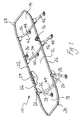
- a bedchair 10 shown in Figure 1 comprises a seat part 12, a backrest part 14 pivotally attached to an intended rear of the seat part 12 at respective hinges or pivots 16, and a footrest part 18 pivotally connected to an intended front of the seat part 12 by means of pivots 20.
- the seat part 12, the backrest part 14 and the footrest part 18 are constituted by sections of an outer tubular frame 22 across which is stretched a fabric sheet 24.
- the seat part 12 is constituted by two generally parallel sections 26 of the tubular frame 22 and that portion of the sheet 24 stretched across those portions of the frame.
- the backrest part 14 of the bedchair 10 is constituted by a generally U-shaped part 28 of the frame 22, as well as that part of the sheet 24 which is stretched thereacross.
- the U-shaped part 28 has its ends pivotally attached respectively to the sections 26 of the frame 22 by means of the pivots 16.
- the footrest part 18 of the bedchair 10 is constituted by a generally U-shaped part 30 of the frame 22, as well as that part of the sheet 24 stretched thereacross.
- the part 30 has its respective ends attached to the front ends of the sections 26 of the frame by way of the pivots 20.
- Each leg arrangement has a pair of substantially parallel legs 38, 40 and 42, which extend downwardly from the frame 22.
- Each leg pair is reinforced by a pair of cross struts 44, 46 and 48.
- One of the leg arrangements 32 is connected at the front of the seat part 12, another of the leg arrangements 34 is attached to the frame 22 towards the rear of the seat part 12, and the other leg arrangement 36 is attached to the frame 22 round about half way along the backrest part 14.
- the leg arrangements 32 and 34 are splayed slightly away from one another to give increased stability to the bedchair 10, and the leg arrangement 36 is on a slant generally parallel to the leg arrangement 34.
- the bedchair 10 shown in Figure 1 with the frame 22 generally horizontal can be folded up for transport and stowage by pivoting the footrest part 18 over and on to the seat part 12 by means of the pivots 20 and the backrest part 14 can be pivoted over and on to both the footrest part 18 and the seat part 12 thus folded together, by means of the pivot 16.
- the leg arrangements 32, 34 and 36 in turn can be pivoted to positions in which they lie flat against this folded arrangement of the frame 22.
- the bedchair 10 When the bedchair 10 is next used, it can be unfolded so that it resumes the configuration it has in Figure 1 .
- each pivot 16 of the bedchair 10 is shown in Figures 2 and 3 . It will be appreciated that both pivots 16 are constructed in the same way with the only exception being that one is a mirror version of the other.
- each pivot 16 comprises two interengaging portions 50 and 52.
- One of the portions 50 of the pivot 16 has an elongate part 54, an extension of which (not shown in Figures 2 and 3 but labeled 90 in Figure 4 ) extends into one of the sections 26 of the tubular frame 22.
- the other portion 52 has a corresponding elongate part 56, an extension of which (not shown in Figures 2 and 3 but labeled 92 in Figure 4 ) extends into one end of the generally U-shaped part 28 of the frame 22.
- An adjustable knob in the form of a rotatable handle 58 is also provided on the pivot 16 in a manner to be described in greater detail in relation to Figures 4 and 5 .
- the interengaging portions 50 and 52 are provided with respective annuli of interengaging castellations 60 and 62.
- Rotation of the handle 58 in an anticlockwise direction separates the interengaging portions 50 and 52 in a manner to be described with reference to Figures 4 and 5 to disengage the annuli of castellations 60 and 62.
- This enables the backrest part 14 to be pivoted about the pivot 16 in relation to the seat part 12.
- the backrest part 14 can be raised from the horizontal position it has as shown in Figure 1 to an angle of substantially 45°to the seat part 12. It can be locked in this position by rotating the handle 58 in a clockwise sense so that the annuli of castellations 60 and 62 become once more interengaged as shown in Figure 2 .
- FIGS 4 and 5 show more completely the annuli of castellations 60 and 62.
- a substantially cylindrical member 64 extends, when the pivot 16 is in the assembled state, through the annulus of castellations 60.
- An outer end of the cylindrical member 64 is provided with a hub 66 with inwardly directed lugs 68 which engage recesses 70 formed on the outside of the annulus of castellations 60 to lock the cylindrical member 64 against rotation about its axis relative to the portion 50.
- a retaining ring 72 engages the cylindrical member 64 at a shoulder portion 74 thereof to inhibit movement of the cylindrical member 64 in an axial direction relative to the annulus of castellations 60.
- the external surface of the cylindrical member 64 is formed with a cam in the form of a slot or groove 75 which is on a slant relative to the axis of the cylindrical member 64.
- a similar groove is formed on the hidden side of the cylindrical member 64 with reference to Figure 5 .
- Two halves 76 of a bearing shell which have the general shape of half of a hollow cylinder, snap-fit around the outside of the cylindrical member 64 so as to be rotatable relative thereto about the axis thereof.
- Each bearing shell half is formed with a cam follower on its interior surface in the form of a spigot 78. The spigot engages an associated one of the grooves 75 on the cylindrical member 64.
- the bearing shell halves 76 are formed with a flange 80 which abuts a shoulder 82 on the inside of the annulus of castellations 62.
- the handle 58 is provided with an internal surface that provides a tight fit around the bearing shell halves 76 so that the handle 58 is on that side of the engagement portion 52 which is further from the engagement portion 50.
- the handle 58 may be rotated in a clockwise direction so that the spigots 78 return to the previous position they had in the grooves 75 so that the interengaging annuli of castellations 60 and 62 are brought together once again, the castellations interengage with one another, and the backrest part 14 is locked in this position relative to the seat part 12.
- each of the elongate parts 54 and 56 is hollow and a spindle 94 extends through this hollow in an axial direction.
- the spindle has a head part 96 which, when the pivot 16 is in the assembled condition as shown in Figure 2 , rests against an internal shoulder 98 within the hollow elongate part 54 or 56 as the case may be.
- the inside surface of the head part 96 is formed with two détente recesses 98 (only one of which is visible in Figure 6 ) spaced apart from one another about the axis of the spindle 94 by 180°.
- a helical compression spring 102 is received in a blind hole 104 formed in the interior of the elongate part 54 or 56 as the case may be, as well as a détente pin 106.
- a wavy washer 108 is used to hold the spindle 94 in position with its head 96 abutting the internal shoulder 100.
- the pin 106 Whilst a yielding of the spring 102 enables the head 96 to adopt an angular position about the axis of the spindle 94, the pin 106 being urged by the spring 102 towards the head 96, tends to hold the spindle 94 in two positions with an angular spacing between one another of about 180° about the axis of the spindle 94, with the détente pin 106 having its outer end engaged with one or other of the recesses 98.
- Each extension 90 or 92 being a projecting part of the spindle 94, is secured within an end of a tubular part 26 or 28 of the frame 22, by means of a retaining pin 110 which extends through holes provided in the relevant section of the tubular frame 22 and one end of the extension 90 or 92.
- the pivot 16 can be flipped, swiveled or rotated about the axis of the spindles 94 from the position it has as shown in Figure 1 to a position angularly spaced therefrom by 180° so that they extend downwardly from the frame 22 instead of upwardly therefrom and no longer create an obstruction to the user's arms or elbows, as shown in Figure 8 .
- Figure 9 shows a view corresponding to that of Figure 1 , with the bedchair 10 as shown therein provided with a cover 200 on it.
- the elongate parts 54 and 56 are provided with flanges 210 at both of their ends, and annular recesses 212 are provided at locations midway between the two flanges 210 of each part 54 and 56, apertures 214 also being provided in the interengaging portions 50 and 52 in registration with the recesses 212 respectively.
- This enables a flexible elongate member 216 to be threaded through holes 218 along the edge of the sheet 24 and around the annular recesses 212.
- the sides of the recesses 212 provide abutment surfaces which inhibit movement of the member 216 out of position. So do the flanges 210 should a part of the member 216 become dislodged from one or both of recesses 212.
- a protuberance 220 projecting outwardly in a longitudinal direction and located on the axis and at that end of one of the interengaging portion 50 which is closer to the other 52, and this protuberance 220 engages a corresponding recess 222 in the other portion 52 when the backrest part 14 is generally co-planar with the seat part 12, to inhibit misalignment of the parts 54 and 56 during use of the bedchair.
Claims (8)
- Chaise-lit (10) ayant une partie formant assise (12) et une partie formant dossier (14) fixée de manière pivotante à l'arrière prévu de la partie formant assise (12), dans laquelle la partie formant dossier (14) peut être fixée dans n'importe quelle position choisie parmi une pluralité de positions angulaires par rapport à la partie formant assise (12) au moyen de parties (50, 52) venant en prise mutuelle respectives fixées respectivement sur la partie formant assise (12) et sur la partie formant dossier (14) et au moins un dispositif de serrage (58, 64, 76) agencé par rapport aux parties (50, 52) venant en prise mutuelle qui peut être réglé pour passer d'une position déverrouillée dans laquelle les parties (50, 52) venant en prise mutuelle peuvent être déplacées l'une par rapport à l'autre afin de permettre de changer le positionnement relatif entre la partie formant dossier (14) et la partie formant assise (12) et une position verrouillée dans laquelle les parties (50, 52) venant en prise mutuelle sont verrouillées en prise l'une avec l'autre afin de retenir la partie formant dossier (14) dans une position angulaire relative choisie par rapport à la partie formant assise (12), caractérisée en ce que les parties (50, 52) venant en prise mutuelle sont respectivement fixées à la partie formant assise (12) et à la partie formant dossier (14) de manière à pouvoir tourner ensemble par rapport auxdites parties formant assise et dossier (12, 14) autour d'axes de rotation fixes respectifs qui sont alignés si, et seulement si, la partie formant dossier (14) est dans une position horizontale prévue sensiblement coplanaire avec la partie formant assise (12), les parties (50, 52) venant en prise mutuelle peuvent être tournées ensemble autour de leurs axes alignés pour passer d'une position au-dessus des parties formant assise (12) et dossier (14) à une partie en dessous de celles-ci.
- Chaise-lit selon la revendication 1, caractérisée en ce que chacune desdites parties (50, 52) venant en prise mutuelle est munie d'une partie allongée (90, 92) qui peut être coulissée dans ou sur une extrémité des parties tubulaires respectives de la partie formant dossier (14) ou de la partie formant assise (12), respectivement.
- Chaise-lit selon la revendication 2, caractérisée en ce que des ouvertures sont ménagées dans les parties allongées (90 ,92) des parties (50, 52) venant en prise mutuelle ainsi que dans les parties tubulaires dans lesquelles ou sur lesquelles elles coulissent pour fixer les parties allongées (90, 92) des parties (50, 52) venant en prise mutuelle pour empêcher toute rotation et tout déplacement longitudinal par rapport aux parties tubulaires de la partie formant dossier (14) et de la partie formant assise (12), respectivement.
- Chaise-lit selon la revendication 2 ou la revendication 3, caractérisée en ce que les parties allongées (90, 92) des parties (50, 52) venant en prise mutuelle peuvent tourner axialement par rapport au reste des parties (50, 52) venant en prise mutuelle dont elles font partie.
- Chaise-lit selon l'une quelconque des revendications 2 à 4, caractérisée en ce qu'une détente élastique (102, 106) est prévue pour empêcher chaque partie allongée (90, 92) de sa partie (50, 52) venant en prise mutuelle associée de tourner axialement dans deux positions écartées selon un angle supérieur à 90°, par exemple de 180°.
- Chaise-lit selon l'une quelconque des revendications précédentes, caractérisée en ce qu'elle comprend un châssis (22) sur lequel est tendu un pan (24) de tissu qui supporte un pêcheur à la ligne lorsque la chaise-lit (10) est utilisée.
- Chaise-lit selon la revendication 6, caractérisée en ce que les parties (50, 52) venant en prise mutuelle viennent en prise dans une position décalée par rapport au châssis (22) et ont d'autres parties (220, 222) venant en prise mutuelle qui sont amenées en prise lorsque la partie formant dossier (14) est généralement coplanaire avec la partie formant assise (12) afin de maintenir les parties adjacents du châssis (22) alignées les unes par rapport aux autres.
- Chaise-lit selon la revendication 6 ou la revendication 7, caractérisée en ce qu'un élément allongé flexible (216) est passé autour du châssis (22) et des parties (50, 52) venant en prise mutuelle ainsi que dans les ouvertures (218) dans le pan (24) afin que ce dernier soit supporté par le châssis (22), et en ce que les parties (50, 52) venant en prise mutuelle sont munies de surfaces de butée pour empêcher que l'élément allongé flexible (216) ne soit délogé de son emplacement.
Applications Claiming Priority (1)
| Application Number | Priority Date | Filing Date | Title |
|---|---|---|---|
| GBGB1002966.8A GB201002966D0 (en) | 2010-02-22 | 2010-02-22 | A bedchair |
Publications (2)
| Publication Number | Publication Date |
|---|---|
| EP2374375A1 EP2374375A1 (fr) | 2011-10-12 |
| EP2374375B1 true EP2374375B1 (fr) | 2013-04-17 |
Family
ID=42114176
Family Applications (1)
| Application Number | Title | Priority Date | Filing Date |
|---|---|---|---|
| EP20110250013 Not-in-force EP2374375B1 (fr) | 2010-02-22 | 2011-01-07 | Chaise-lit |
Country Status (2)
| Country | Link |
|---|---|
| EP (1) | EP2374375B1 (fr) |
| GB (1) | GB201002966D0 (fr) |
Families Citing this family (3)
| Publication number | Priority date | Publication date | Assignee | Title |
|---|---|---|---|---|
| GB2482684A (en) * | 2010-08-09 | 2012-02-15 | Catchum 88 Ltd | Hinge mechanism for folding bed |
| NL2022326B1 (nl) | 2018-12-28 | 2020-08-13 | F Smit Holding B V | Stoel, in het bijzonder voor videospellen, en daarbij toe te passen scharnier |
| EP4338643A1 (fr) * | 2022-09-16 | 2024-03-20 | Pagotto S.r.l. - Socio Unico | Joint rotatif |
Family Cites Families (2)
| Publication number | Priority date | Publication date | Assignee | Title |
|---|---|---|---|---|
| GB2344510A (en) * | 1998-12-03 | 2000-06-14 | Fox Design Int | Bed-chair or other support means |
| GB0329395D0 (en) * | 2003-12-19 | 2004-01-21 | Jrc Products Ltd | Improvements in and relating to folding seats |
-
2010
- 2010-02-22 GB GBGB1002966.8A patent/GB201002966D0/en not_active Ceased
-
2011
- 2011-01-07 EP EP20110250013 patent/EP2374375B1/fr not_active Not-in-force
Also Published As
| Publication number | Publication date |
|---|---|
| EP2374375A1 (fr) | 2011-10-12 |
| GB201002966D0 (en) | 2010-04-07 |
Similar Documents
| Publication | Publication Date | Title |
|---|---|---|
| EP2865290B1 (fr) | Bâton de marche convertible en siège | |
| US8205943B2 (en) | Foldable rocking chair | |
| US9179646B2 (en) | Walking aid for disabled four-legged animals | |
| CN209152740U (zh) | 折叠椅 | |
| US4715650A (en) | Fully collapsible portable chair | |
| JP6753576B2 (ja) | 折り畳み式椅子 | |
| US9504297B2 (en) | Foldable chair | |
| US20070216201A1 (en) | Seating device with a foldable table | |
| WO2005068895A1 (fr) | Trepied compact | |
| JP6400563B2 (ja) | バウンサーまたは反動揺りかご、およびそのフレーム | |
| EP2595865B1 (fr) | Bicyclette pliable | |
| US20220386779A1 (en) | Portable folding chair | |
| EP2374375B1 (fr) | Chaise-lit | |
| US20040094997A1 (en) | Collapsible chair with sliding rigid armrest | |
| JP7431215B2 (ja) | 頭部支持組立体及び支持ユニット | |
| US20190254432A1 (en) | Collapsible Support Structure | |
| US7422275B2 (en) | Folding push chair | |
| US7195310B2 (en) | Collapsible chair with adjustable backrest | |
| WO2015073700A1 (fr) | Dispositif lombaire portatif pliable | |
| EP2417874A1 (fr) | Charnière pour chaise-lit pliable | |
| AU2019100879A4 (en) | Chair seat sliding and locking mechanism | |
| EP3785570B1 (fr) | Assise de chaise avec mécanisme de coulissement et de verrouillage | |
| CA3060300C (fr) | Siege de fauteuil et mecanisme de verrouillage | |
| US10820702B1 (en) | Chair seat sliding and locking mechanism | |
| AU683175B2 (en) | Collapsible trolley |
Legal Events
| Date | Code | Title | Description |
|---|---|---|---|
| PUAI | Public reference made under article 153(3) epc to a published international application that has entered the european phase |
Free format text: ORIGINAL CODE: 0009012 |
|
| AK | Designated contracting states |
Kind code of ref document: A1 Designated state(s): AL AT BE BG CH CY CZ DE DK EE ES FI FR GB GR HR HU IE IS IT LI LT LU LV MC MK MT NL NO PL PT RO RS SE SI SK SM TR |
|
| AX | Request for extension of the european patent |
Extension state: BA ME |
|
| 17P | Request for examination filed |
Effective date: 20120329 |
|
| GRAP | Despatch of communication of intention to grant a patent |
Free format text: ORIGINAL CODE: EPIDOSNIGR1 |
|
| RIC1 | Information provided on ipc code assigned before grant |
Ipc: A47C 1/026 20060101ALI20121026BHEP Ipc: A47C 17/70 20060101AFI20121026BHEP |
|
| GRAS | Grant fee paid |
Free format text: ORIGINAL CODE: EPIDOSNIGR3 |
|
| GRAA | (expected) grant |
Free format text: ORIGINAL CODE: 0009210 |
|
| AK | Designated contracting states |
Kind code of ref document: B1 Designated state(s): AL AT BE BG CH CY CZ DE DK EE ES FI FR GB GR HR HU IE IS IT LI LT LU LV MC MK MT NL NO PL PT RO RS SE SI SK SM TR |
|
| REG | Reference to a national code |
Ref country code: GB Ref legal event code: FG4D |
|
| REG | Reference to a national code |
Ref country code: CH Ref legal event code: EP |
|
| REG | Reference to a national code |
Ref country code: IE Ref legal event code: FG4D |
|
| REG | Reference to a national code |
Ref country code: AT Ref legal event code: REF Ref document number: 606705 Country of ref document: AT Kind code of ref document: T Effective date: 20130515 |
|
| REG | Reference to a national code |
Ref country code: DE Ref legal event code: R096 Ref document number: 602011001391 Country of ref document: DE Effective date: 20130606 |
|
| REG | Reference to a national code |
Ref country code: NL Ref legal event code: T3 |
|
| REG | Reference to a national code |
Ref country code: LT Ref legal event code: MG4D |
|
| PG25 | Lapsed in a contracting state [announced via postgrant information from national office to epo] |
Ref country code: PT Free format text: LAPSE BECAUSE OF FAILURE TO SUBMIT A TRANSLATION OF THE DESCRIPTION OR TO PAY THE FEE WITHIN THE PRESCRIBED TIME-LIMIT Effective date: 20130819 Ref country code: SE Free format text: LAPSE BECAUSE OF FAILURE TO SUBMIT A TRANSLATION OF THE DESCRIPTION OR TO PAY THE FEE WITHIN THE PRESCRIBED TIME-LIMIT Effective date: 20130417 Ref country code: LT Free format text: LAPSE BECAUSE OF FAILURE TO SUBMIT A TRANSLATION OF THE DESCRIPTION OR TO PAY THE FEE WITHIN THE PRESCRIBED TIME-LIMIT Effective date: 20130417 Ref country code: NO Free format text: LAPSE BECAUSE OF FAILURE TO SUBMIT A TRANSLATION OF THE DESCRIPTION OR TO PAY THE FEE WITHIN THE PRESCRIBED TIME-LIMIT Effective date: 20130717 Ref country code: SI Free format text: LAPSE BECAUSE OF FAILURE TO SUBMIT A TRANSLATION OF THE DESCRIPTION OR TO PAY THE FEE WITHIN THE PRESCRIBED TIME-LIMIT Effective date: 20130417 Ref country code: FI Free format text: LAPSE BECAUSE OF FAILURE TO SUBMIT A TRANSLATION OF THE DESCRIPTION OR TO PAY THE FEE WITHIN THE PRESCRIBED TIME-LIMIT Effective date: 20130417 Ref country code: IS Free format text: LAPSE BECAUSE OF FAILURE TO SUBMIT A TRANSLATION OF THE DESCRIPTION OR TO PAY THE FEE WITHIN THE PRESCRIBED TIME-LIMIT Effective date: 20130817 Ref country code: ES Free format text: LAPSE BECAUSE OF FAILURE TO SUBMIT A TRANSLATION OF THE DESCRIPTION OR TO PAY THE FEE WITHIN THE PRESCRIBED TIME-LIMIT Effective date: 20130728 Ref country code: GR Free format text: LAPSE BECAUSE OF FAILURE TO SUBMIT A TRANSLATION OF THE DESCRIPTION OR TO PAY THE FEE WITHIN THE PRESCRIBED TIME-LIMIT Effective date: 20130718 |
|
| PG25 | Lapsed in a contracting state [announced via postgrant information from national office to epo] |
Ref country code: CY Free format text: LAPSE BECAUSE OF FAILURE TO SUBMIT A TRANSLATION OF THE DESCRIPTION OR TO PAY THE FEE WITHIN THE PRESCRIBED TIME-LIMIT Effective date: 20130417 Ref country code: HR Free format text: LAPSE BECAUSE OF FAILURE TO SUBMIT A TRANSLATION OF THE DESCRIPTION OR TO PAY THE FEE WITHIN THE PRESCRIBED TIME-LIMIT Effective date: 20130417 Ref country code: LV Free format text: LAPSE BECAUSE OF FAILURE TO SUBMIT A TRANSLATION OF THE DESCRIPTION OR TO PAY THE FEE WITHIN THE PRESCRIBED TIME-LIMIT Effective date: 20130417 Ref country code: PL Free format text: LAPSE BECAUSE OF FAILURE TO SUBMIT A TRANSLATION OF THE DESCRIPTION OR TO PAY THE FEE WITHIN THE PRESCRIBED TIME-LIMIT Effective date: 20130417 Ref country code: BG Free format text: LAPSE BECAUSE OF FAILURE TO SUBMIT A TRANSLATION OF THE DESCRIPTION OR TO PAY THE FEE WITHIN THE PRESCRIBED TIME-LIMIT Effective date: 20130717 Ref country code: RS Free format text: LAPSE BECAUSE OF FAILURE TO SUBMIT A TRANSLATION OF THE DESCRIPTION OR TO PAY THE FEE WITHIN THE PRESCRIBED TIME-LIMIT Effective date: 20130417 |
|
| REG | Reference to a national code |
Ref country code: HU Ref legal event code: AG4A Ref document number: E017606 Country of ref document: HU |
|
| PG25 | Lapsed in a contracting state [announced via postgrant information from national office to epo] |
Ref country code: SK Free format text: LAPSE BECAUSE OF FAILURE TO SUBMIT A TRANSLATION OF THE DESCRIPTION OR TO PAY THE FEE WITHIN THE PRESCRIBED TIME-LIMIT Effective date: 20130417 Ref country code: DK Free format text: LAPSE BECAUSE OF FAILURE TO SUBMIT A TRANSLATION OF THE DESCRIPTION OR TO PAY THE FEE WITHIN THE PRESCRIBED TIME-LIMIT Effective date: 20130417 Ref country code: CZ Free format text: LAPSE BECAUSE OF FAILURE TO SUBMIT A TRANSLATION OF THE DESCRIPTION OR TO PAY THE FEE WITHIN THE PRESCRIBED TIME-LIMIT Effective date: 20130417 Ref country code: EE Free format text: LAPSE BECAUSE OF FAILURE TO SUBMIT A TRANSLATION OF THE DESCRIPTION OR TO PAY THE FEE WITHIN THE PRESCRIBED TIME-LIMIT Effective date: 20130417 |
|
| PLBE | No opposition filed within time limit |
Free format text: ORIGINAL CODE: 0009261 |
|
| STAA | Information on the status of an ep patent application or granted ep patent |
Free format text: STATUS: NO OPPOSITION FILED WITHIN TIME LIMIT |
|
| PG25 | Lapsed in a contracting state [announced via postgrant information from national office to epo] |
Ref country code: RO Free format text: LAPSE BECAUSE OF FAILURE TO SUBMIT A TRANSLATION OF THE DESCRIPTION OR TO PAY THE FEE WITHIN THE PRESCRIBED TIME-LIMIT Effective date: 20130417 |
|
| 26N | No opposition filed |
Effective date: 20140120 |
|
| REG | Reference to a national code |
Ref country code: DE Ref legal event code: R097 Ref document number: 602011001391 Country of ref document: DE Effective date: 20140120 |
|
| PG25 | Lapsed in a contracting state [announced via postgrant information from national office to epo] |
Ref country code: LU Free format text: LAPSE BECAUSE OF FAILURE TO SUBMIT A TRANSLATION OF THE DESCRIPTION OR TO PAY THE FEE WITHIN THE PRESCRIBED TIME-LIMIT Effective date: 20140107 |
|
| REG | Reference to a national code |
Ref country code: CH Ref legal event code: PL |
|
| PG25 | Lapsed in a contracting state [announced via postgrant information from national office to epo] |
Ref country code: LI Free format text: LAPSE BECAUSE OF NON-PAYMENT OF DUE FEES Effective date: 20140131 Ref country code: CH Free format text: LAPSE BECAUSE OF NON-PAYMENT OF DUE FEES Effective date: 20140131 |
|
| REG | Reference to a national code |
Ref country code: IE Ref legal event code: MM4A |
|
| REG | Reference to a national code |
Ref country code: FR Ref legal event code: PLFP Year of fee payment: 5 |
|
| PG25 | Lapsed in a contracting state [announced via postgrant information from national office to epo] |
Ref country code: IE Free format text: LAPSE BECAUSE OF NON-PAYMENT OF DUE FEES Effective date: 20140107 |
|
| PG25 | Lapsed in a contracting state [announced via postgrant information from national office to epo] |
Ref country code: MC Free format text: LAPSE BECAUSE OF FAILURE TO SUBMIT A TRANSLATION OF THE DESCRIPTION OR TO PAY THE FEE WITHIN THE PRESCRIBED TIME-LIMIT Effective date: 20130417 |
|
| REG | Reference to a national code |
Ref country code: FR Ref legal event code: PLFP Year of fee payment: 6 |
|
| PG25 | Lapsed in a contracting state [announced via postgrant information from national office to epo] |
Ref country code: MT Free format text: LAPSE BECAUSE OF FAILURE TO SUBMIT A TRANSLATION OF THE DESCRIPTION OR TO PAY THE FEE WITHIN THE PRESCRIBED TIME-LIMIT Effective date: 20130417 |
|
| PG25 | Lapsed in a contracting state [announced via postgrant information from national office to epo] |
Ref country code: SM Free format text: LAPSE BECAUSE OF FAILURE TO SUBMIT A TRANSLATION OF THE DESCRIPTION OR TO PAY THE FEE WITHIN THE PRESCRIBED TIME-LIMIT Effective date: 20130417 |
|
| PG25 | Lapsed in a contracting state [announced via postgrant information from national office to epo] |
Ref country code: TR Free format text: LAPSE BECAUSE OF FAILURE TO SUBMIT A TRANSLATION OF THE DESCRIPTION OR TO PAY THE FEE WITHIN THE PRESCRIBED TIME-LIMIT Effective date: 20130417 |
|
| REG | Reference to a national code |
Ref country code: FR Ref legal event code: PLFP Year of fee payment: 7 |
|
| REG | Reference to a national code |
Ref country code: HU Ref legal event code: HC9C Owner name: FOX INTERNATIONAL GROUP LIMITED, GB Free format text: FORMER OWNER(S): FOX INTERNATIONAL GROUP LIMITED, GB |
|
| REG | Reference to a national code |
Ref country code: FR Ref legal event code: PLFP Year of fee payment: 8 |
|
| REG | Reference to a national code |
Ref country code: FR Ref legal event code: CA Effective date: 20180205 |
|
| REG | Reference to a national code |
Ref country code: DE Ref legal event code: R082 Ref document number: 602011001391 Country of ref document: DE Representative=s name: LS-MP VON PUTTKAMER BERNGRUBER LOTH SPUHLER MU, DE Ref country code: DE Ref legal event code: R081 Ref document number: 602011001391 Country of ref document: DE Owner name: FOX INTERNATIONAL GROUP LTD., WARLEY, GB Free format text: FORMER OWNER: FOX INTERNATIONAL GROUP LTD., HAINAULT, ESSEX, GB |
|
| PG25 | Lapsed in a contracting state [announced via postgrant information from national office to epo] |
Ref country code: MK Free format text: LAPSE BECAUSE OF FAILURE TO SUBMIT A TRANSLATION OF THE DESCRIPTION OR TO PAY THE FEE WITHIN THE PRESCRIBED TIME-LIMIT Effective date: 20130417 |
|
| PG25 | Lapsed in a contracting state [announced via postgrant information from national office to epo] |
Ref country code: AL Free format text: LAPSE BECAUSE OF FAILURE TO SUBMIT A TRANSLATION OF THE DESCRIPTION OR TO PAY THE FEE WITHIN THE PRESCRIBED TIME-LIMIT Effective date: 20130417 |
|
| PGFP | Annual fee paid to national office [announced via postgrant information from national office to epo] |
Ref country code: FR Payment date: 20210127 Year of fee payment: 11 Ref country code: IT Payment date: 20210121 Year of fee payment: 11 Ref country code: NL Payment date: 20210126 Year of fee payment: 11 |
|
| PGFP | Annual fee paid to national office [announced via postgrant information from national office to epo] |
Ref country code: GB Payment date: 20210129 Year of fee payment: 11 Ref country code: HU Payment date: 20210102 Year of fee payment: 11 Ref country code: AT Payment date: 20210127 Year of fee payment: 11 Ref country code: BE Payment date: 20210127 Year of fee payment: 11 |
|
| PGFP | Annual fee paid to national office [announced via postgrant information from national office to epo] |
Ref country code: DE Payment date: 20210329 Year of fee payment: 11 |
|
| REG | Reference to a national code |
Ref country code: DE Ref legal event code: R119 Ref document number: 602011001391 Country of ref document: DE |
|
| REG | Reference to a national code |
Ref country code: NL Ref legal event code: MM Effective date: 20220201 |
|
| REG | Reference to a national code |
Ref country code: AT Ref legal event code: MM01 Ref document number: 606705 Country of ref document: AT Kind code of ref document: T Effective date: 20220107 |
|
| GBPC | Gb: european patent ceased through non-payment of renewal fee |
Effective date: 20220107 |
|
| REG | Reference to a national code |
Ref country code: BE Ref legal event code: MM Effective date: 20220131 |
|
| PG25 | Lapsed in a contracting state [announced via postgrant information from national office to epo] |
Ref country code: NL Free format text: LAPSE BECAUSE OF NON-PAYMENT OF DUE FEES Effective date: 20220201 Ref country code: GB Free format text: LAPSE BECAUSE OF NON-PAYMENT OF DUE FEES Effective date: 20220107 Ref country code: DE Free format text: LAPSE BECAUSE OF NON-PAYMENT OF DUE FEES Effective date: 20220802 Ref country code: AT Free format text: LAPSE BECAUSE OF NON-PAYMENT OF DUE FEES Effective date: 20220107 |
|
| PG25 | Lapsed in a contracting state [announced via postgrant information from national office to epo] |
Ref country code: HU Free format text: LAPSE BECAUSE OF NON-PAYMENT OF DUE FEES Effective date: 20220108 Ref country code: FR Free format text: LAPSE BECAUSE OF NON-PAYMENT OF DUE FEES Effective date: 20220131 Ref country code: BE Free format text: LAPSE BECAUSE OF NON-PAYMENT OF DUE FEES Effective date: 20220131 |
|
| PG25 | Lapsed in a contracting state [announced via postgrant information from national office to epo] |
Ref country code: IT Free format text: LAPSE BECAUSE OF NON-PAYMENT OF DUE FEES Effective date: 20220107 |