EP2373924B2 - Improvements in or relating to waveguides - Google Patents
Improvements in or relating to waveguides Download PDFInfo
- Publication number
- EP2373924B2 EP2373924B2 EP09768226.4A EP09768226A EP2373924B2 EP 2373924 B2 EP2373924 B2 EP 2373924B2 EP 09768226 A EP09768226 A EP 09768226A EP 2373924 B2 EP2373924 B2 EP 2373924B2
- Authority
- EP
- European Patent Office
- Prior art keywords
- light
- waveguide
- channel
- image bearing
- waveguide element
- Prior art date
- Legal status (The legal status is an assumption and is not a legal conclusion. Google has not performed a legal analysis and makes no representation as to the accuracy of the status listed.)
- Active
Links
Images


Classifications
-
- G—PHYSICS
- G02—OPTICS
- G02B—OPTICAL ELEMENTS, SYSTEMS OR APPARATUS
- G02B27/00—Optical systems or apparatus not provided for by any of the groups G02B1/00 - G02B26/00, G02B30/00
- G02B27/10—Beam splitting or combining systems
- G02B27/1006—Beam splitting or combining systems for splitting or combining different wavelengths
-
- G—PHYSICS
- G02—OPTICS
- G02B—OPTICAL ELEMENTS, SYSTEMS OR APPARATUS
- G02B27/00—Optical systems or apparatus not provided for by any of the groups G02B1/00 - G02B26/00, G02B30/00
- G02B27/01—Head-up displays
- G02B27/0101—Head-up displays characterised by optical features
-
- G—PHYSICS
- G02—OPTICS
- G02B—OPTICAL ELEMENTS, SYSTEMS OR APPARATUS
- G02B27/00—Optical systems or apparatus not provided for by any of the groups G02B1/00 - G02B26/00, G02B30/00
- G02B27/10—Beam splitting or combining systems
- G02B27/1086—Beam splitting or combining systems operating by diffraction only
-
- G—PHYSICS
- G02—OPTICS
- G02B—OPTICAL ELEMENTS, SYSTEMS OR APPARATUS
- G02B27/00—Optical systems or apparatus not provided for by any of the groups G02B1/00 - G02B26/00, G02B30/00
- G02B27/10—Beam splitting or combining systems
- G02B27/14—Beam splitting or combining systems operating by reflection only
- G02B27/145—Beam splitting or combining systems operating by reflection only having sequential partially reflecting surfaces
-
- G—PHYSICS
- G02—OPTICS
- G02B—OPTICAL ELEMENTS, SYSTEMS OR APPARATUS
- G02B6/00—Light guides; Structural details of arrangements comprising light guides and other optical elements, e.g. couplings
- G02B6/0001—Light guides; Structural details of arrangements comprising light guides and other optical elements, e.g. couplings specially adapted for lighting devices or systems
- G02B6/0011—Light guides; Structural details of arrangements comprising light guides and other optical elements, e.g. couplings specially adapted for lighting devices or systems the light guides being planar or of plate-like form
- G02B6/0033—Means for improving the coupling-out of light from the light guide
- G02B6/0035—Means for improving the coupling-out of light from the light guide provided on the surface of the light guide or in the bulk of it
-
- G—PHYSICS
- G02—OPTICS
- G02B—OPTICAL ELEMENTS, SYSTEMS OR APPARATUS
- G02B6/00—Light guides; Structural details of arrangements comprising light guides and other optical elements, e.g. couplings
- G02B6/0001—Light guides; Structural details of arrangements comprising light guides and other optical elements, e.g. couplings specially adapted for lighting devices or systems
- G02B6/0011—Light guides; Structural details of arrangements comprising light guides and other optical elements, e.g. couplings specially adapted for lighting devices or systems the light guides being planar or of plate-like form
- G02B6/0066—Light guides; Structural details of arrangements comprising light guides and other optical elements, e.g. couplings specially adapted for lighting devices or systems the light guides being planar or of plate-like form characterised by the light source being coupled to the light guide
- G02B6/0068—Arrangements of plural sources, e.g. multi-colour light sources
-
- G—PHYSICS
- G02—OPTICS
- G02B—OPTICAL ELEMENTS, SYSTEMS OR APPARATUS
- G02B27/00—Optical systems or apparatus not provided for by any of the groups G02B1/00 - G02B26/00, G02B30/00
- G02B27/01—Head-up displays
- G02B27/0101—Head-up displays characterised by optical features
- G02B2027/0123—Head-up displays characterised by optical features comprising devices increasing the field of view
- G02B2027/0125—Field-of-view increase by wavefront division
-
- G—PHYSICS
- G02—OPTICS
- G02B—OPTICAL ELEMENTS, SYSTEMS OR APPARATUS
- G02B5/00—Optical elements other than lenses
- G02B5/18—Diffraction gratings
-
- G—PHYSICS
- G02—OPTICS
- G02B—OPTICAL ELEMENTS, SYSTEMS OR APPARATUS
- G02B6/00—Light guides; Structural details of arrangements comprising light guides and other optical elements, e.g. couplings
-
- G—PHYSICS
- G02—OPTICS
- G02B—OPTICAL ELEMENTS, SYSTEMS OR APPARATUS
- G02B6/00—Light guides; Structural details of arrangements comprising light guides and other optical elements, e.g. couplings
- G02B6/0001—Light guides; Structural details of arrangements comprising light guides and other optical elements, e.g. couplings specially adapted for lighting devices or systems
- G02B6/0011—Light guides; Structural details of arrangements comprising light guides and other optical elements, e.g. couplings specially adapted for lighting devices or systems the light guides being planar or of plate-like form
- G02B6/0075—Arrangements of multiple light guides
- G02B6/0076—Stacked arrangements of multiple light guides of the same or different cross-sectional area
Definitions
- This invention relates to a waveguide and a projection display for displaying an image to an observer, which is particularly, but not exclusively, suitable for use in a head up display, a helmet mounted display or head mounted display.
- the invention is defined in the appended set of claims.
- prior art International patent application publication number WO2007/029032 teaches a projection display 10 for displaying an image to an observer 12 that uses waveguide techniques to generate a collimated display defining a large exit pupil at the point of the observer 12 and a large field of view, whilst using a small image-providing light source device.
- the projection display 10 uses a first plate-like waveguide 14 made of light transmissive material such as glass or plastic and a second plate-like waveguide 16 made from a light transmissive and light transparent material such as glass or plastic.
- the projection display 10 additionally includes an image-providing light source device, not shown, located to inject image bearing light into the first plate-like waveguide 14 through a first face 18.
- the image-providing light source device includes a micro-display arranged to provide information to be displayed to the observer 12. Additionally the image-providing light source device includes a collimating optical arrangement located between the micro-display and the first face 18 of the first plate-like waveguide 14. The collimating optical arrangement is operable to collimate light received from the micro-display and to inject the collimated image bearing light into the first plate-like waveguide 14 through the first face 18.
- the collimated image bearing light produced by the collimating optical arrangement has a small exit pupil and is fed into the first plate-like waveguide 14, which performs the function of stretching the horizontal pupil of the final display.
- the output from the first plate-like waveguide 14 is fed into the second plate-like waveguide 16, which is arranged to stretch the vertical pupil of the final display and also to act as a combiner for the projection display 10 through which the observer 12 views an outside world scene 20 along a line of sight 22 of the observer 12 through the second plate-like waveguide 16 with information to be displayed to the observer 12 overlaid on the outside world scene 20.
- the image to be displayed to the observer 12 looking through the second plate-like waveguide 16 defines a large exit pupil and a large field of view whilst using a small image generating light source.
- Image bearing light injected into the first plate-like waveguide 14, via first face 18 is incident on a first grating 24 arranged internally within the first plate-like waveguide 14 and substantially parallel with the first face 18.
- Light impinging on the first grating 24 diffracts therefrom such that the incidence angle of the light on the internal surfaces of the first plate-like waveguide 14 is greater than the critical angle for the material from which the first plate-like waveguide 14 is made.
- the image bearing light is constrained within the first plate-like waveguide 14 to propagate along the first plate-like waveguide 14 reflecting from each internal surface in turn to follow a predefined light path 26.
- the relative field angles of the light incident on the first plate-like waveguide 14 at the first face 18 are preserved within the first plate-like waveguide 14 and the information required to regenerate the original image is preserved.
- the first grating 24 also serves to radiate the image bearing light out of the first plate-like waveguide 14.
- the first grating 24 is a low efficiency grating which diffracts a small amount of light out of the first plate-like waveguide 14 on each interaction with incident image bearing light.
- the second plate-like waveguide 16 is located with a first face 28 parallel with a second face 30 of the first plate-like waveguide 14 and is arranged to receive the image bearing light exiting the second face 30 of the first plate-like waveguide 14.
- the second face 30 is parallel to the first face 18 of the first plate-like waveguide 14.
- the first face 28 of the second plate-like waveguide 16 is located adjacent and close to the second face 30 of the first plate-like waveguide 14.
- the second plate-like waveguide 16 includes a second grating 32 located therein arranged substantially parallel to the first face 28 of the second plate-like waveguide 16 and the second grating 32 is operable to diffract each impinging ray of image bearing light received from the first grating 24 of the first plate-like waveguide 14 at an angle that is larger than the critical angle for the material from which the second plate-like waveguide 16 is made. Accordingly, received image bearing light will propagate inside the second plate-like waveguide 16 to follow the predefined light path 26. The image bearing light continues along the light path 26 to a third grating 34 arranged on or within the second plate-like waveguide 16, which is arranged to diffract the received image bearing light out of the second plate-like waveguide 16 towards the observer 12.
- the second grating 32 is arranged such that its diffractive power is rotated through 90 degrees to that of the diffractive power of the parallel first grating 24 to rotate incident image bearing light towards the third grating 34.
- the third grating 34 is a low efficiency grating, such that as image bearing light propagates along the light path 26 within the second plate-like waveguide 16, each interaction with the third grating 34 causes a small proportion of the image bearing light to be diffracted out of the second plate-like waveguide 16. Image bearing light which is not diffracted out of the second plate-like waveguide 16 continues to propagate within the second plate-like waveguide 16. Accordingly, a large number of parallel rays of image bearing light exit the second plate-like waveguide 16 through the third grating 34 towards the observer 12, which originated at discrete points on the micro-display forming the image generating light source device. As the relative field angles of the image bearing light have been preserved within the first and second plate-like waveguides 14, 16, the correct image to be conveyed to the observer 12 is presented for viewing when the observer 12 views an outside world scene 20 through the second plate-like waveguide 16.
- Such a projection display 10 is only arranged to present a single colour image to the observer 12.
- image bearing light injected into the substrate of material is maintained in separation dependent on wavelength, which may be according to its primary colours, for example red, green and blue wavelengths of light, and the image bearing light within each channel is transmitted by total internal reflection within the substrate of material. Accordingly, image bearing light of different wavelengths can be transmitted in separate channels within the substrate, each channel being optimised to transmit a particular wavelength of image bearing light, thereby mitigating chromatic dispersion or colour unevenness associated with injecting image bearing light of a wide wavelength into a single channel prior art projection display.
- Each channel may be arranged to transmit light of a predefined wavelength or range of wavelengths.
- the channels may be configured to transmit light in red, green and blue wavelengths.
- the channels could be configured to transmit light in yellow, red and blue wavelengths.
- the arrangement can provide chromatically separated light transmission across three different colour bands which when reconstituted into a final image displayed to a viewer can reproduce a full optical spectrum by combining different proportions of the chromatically separated light.
- light may be separated into the three distinct colours, alternatively light may be separated into a number of separate wavelength ranges, for example, “red” in the range of 590 to 750 nm, “green” in the range 495 and 590 nm, and “blue” in the range 380 and 495 nm.
- a first channel may be arranged to carry the red wavelength of light
- a second channel may be arranged to arranged to carry the green wavelength of light
- a third channel may be arranged to carry the blue wavelength of light.
- At least one filter may be arranged to separate light dependent on wavelength prior to transmission within a channel. At least one filter may be carried on or within the substrate of material.
- light may be separated dependent on wavelength prior to injection into the substrate of material.
- Each grating may be arranged to diffract light out of the substrate of material the light being substantially parallel with light diffracted out of the substrate of material by each other grating within another channel.
- the grating may be a holographic optical element.
- the channels may have respective optical elements for injecting image bearing light into the channels, wherein the optical elements are configured for injecting image bearing light only within respective said predefined wavelengths into the channels and allowing image bearing light outside of those respective predefined wavelengths to pass therethrough.
- the arrangement separates image bearing into component wavelengths and injects those separate wavelengths into the respective channel.
- image bearing light injected into the first waveguide element is maintained in separation dependent on wavelength, for example red, green and blue wavelengths of light, and the image bearing light is transmitted by total internal reflection within a separate channel in both the first and the second waveguides dependent on the wavelength of the image bearing light. Accordingly, a colour field of view of the image can be conveyed to an observer.
- Each channel of the first and second waveguides can be optimised to transmit a particular wavelength of image bearing light, thereby mitigating chromatic dispersion or colour unevenness.
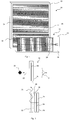
- a waveguide apparatus 40 includes a substrate of material 42 having first and second layers 44 and 46 arranged within the substrate of material 42 so as to define separate first, second and third channels 48, 50 and 52.
- the first and second layers can be formed from a thin film dielectric coating.
- the channels, 48, 50, 52 are arranged to transmit light in respective predefined wavelengths or wavelength ranges within the channel 48, 50, 52 under total internal reflection.
- the first channel 48 is arranged to transmit light in a first wavelength range and in this example, the first channel transmits light in a red wavelength range of image bearing light R (e.g. in the range between about 590 to 750 nm).
- the second channel 50 is arranged to transmit light in a second wavelength range and in this example, the second channel transmits light in a green wavelength range of image bearing light G (e.g. in the range between about 495 and 590 nm).
- the third channel 52 is arranged to transmit light in a third predetermined wavelength range and in this example, the third channel transmits light in a blue wavelength range of image bearing light B (e.g. in the range between about 380 and 495 nm).
- each channel 48, 50, 52 has a grating 54, 56, 58 within the channel 48, 50, 52 that is arranged to diffract a portion of image bearing light incident thereon out of the substrate of material 42 and to allow the remainder of the image bearing light incident thereon to be transmitted in its respective channel 48, 50, 52 under total internal reflection.
- Image bearing light passing through the grating 54, 56, 58 continues along a light path 60, 62, 64 towards a distal end 66 of the substrate of material 42 to further interact with the grating 54, 56, 58 associate with the channel 48, 50, 52.
- the image bearing light interacts with the grating 54, such that a portion R1, R2, R3, R4 is diffracted out of the substrate of material 42 upon each interaction.
- the image bearing light interacts with the grating 56, such that a portion G1, G2, G3, G4 is diffracted out of the substrate of material 42 upon each interaction.
- the blue wavelengths of image bearing light B follow the light path 64 under total internal reflection between the second layer 46 and second face 70 of the substrate of material 42.
- the image bearing light interacts with the grating 58, such that a portion B1, B2, B3, B4 is diffracted out of the substrate of material 42 upon each interaction.
- a number of pupils of image bearing light 72, 74, 76, 78 are formed by the red, green and blue outputs from the substrate of material 42, that is pupil 72 is formed from R1, G1 and B1, pupil 74 is formed from R2, G2 and B2, pupil 76 is formed from R3, G3 and B3 and pupil 78 is formed from R4, G4 and B4.
- the pupils of image bearing light 72, 74, 76, 78 when viewed by an observer, not shown, will convey an image to the observer. It will be appreciated that the arrangement provides a single combiner in the form of the substrate for the image bearing light in separate wavelengths.
- image bearing light is injected into the substrate of material 42 via separate optical elements for each channel 48, 50, 52. That is, the red, green and blue wavelengths of image bearing light R, G, B, are separated prior to injection into the appropriate channel 48, 50, 52 of the substrate of material 42.
- the red, green and blue wavelengths may be within relatively narrow ranges and selected in order to reproduce an image of the required colour in the final viewed image.
- the red wavelengths of image bearing light R enter the first channel 48 via a reflective element 80 and follow light path 60 between first face 68 of the substrate of material 42 and the first layer 44.
- the green wavelengths of image bearing light G enter the second channel 50 via a reflective element 82 and follow light path 62 between first layer 44 and second layer 46.
- the blue wavelengths of image bearing light B enter the third channel 52 via a reflective element 84 and follow light path 64 between the second layer 46 and the second face 70 of the substrate of material 42.
- an apparatus 90 to separate an image to be conveyed to an observer, not shown, into red, green and blue wavelengths of image bearing light A suitable image-providing light source device 92 is arranged to inject image bearing light into the apparatus 90.
- the image bearing light is split or filtered to provide a red channel R by a first optical element 94.
- the image bearing light associated with the red channel R is then reflected by a suitable mirror 96 to allow injection into the waveguide apparatus, for example 40 of Figure 4 .
- the green and blue components of the image bearing light pass through the first optical element 94 and is split or filtered to provide separate green and blue channels G, B by a second optical element 98.
- the image bearing light associated with the green channel G passes through the second optical element 98 and the image bearing light associated with the blue channel B is reflected by a suitable mirror 100 to allow injection into the waveguide apparatus 40.
- image bearing light is injected into the substrate of material 42 via a single point.
- the red, green and blue wavelengths of image bearing light are separated by optical elements associated with each channel as the image bearing light passes into the channel 48, 50, 52.
- the red, green and blue wavelengths of image bearing light R, G, B enter the first channel 48 and are filtered or split by a first optical element 102 such that the green and blue wavelengths of image bearing light G, B pass through the first optical element 102 into the second channel 50, whilst the red wavelengths of image bearing light R follow light path 60 between first face 68 of the substrate of material 42 and the first layer 44.
- the green and blue wavelengths of image bearing light G,B enter the second channel 50 and are filtered or split by a second optical element 104 such that the blue wavelengths of image bearing light B pass through the second optical element 104 into the third channel 52, whilst the green wavelengths of image bearing light G follow light path 62 between first layer 44 and second layer 46.
- the blue wavelengths of image bearing light B enter the third channel 52 and are reflected by a third optical element 106 such that the blue wavelengths of image bearing light B follow light path 64 between the second layer 46 and the second face 70 of the substrate of material 42.
- the injection of image bearing light into a waveguide element 40 can be via one or more reflective, transmissive or refractive optical elements.
- the grating elements 54, 56, 58 can be reflective, thereby being arranged on or near an internal surface of a channel 48, 50, 52 or transmissive, thereby being arranged towards the centre of the channel 48, 50, 52.
- a substrate of material 42 having three channels 48, 50, 52 can have a crosstalk component associated with each of the wavelengths of image bearing light required to pass through a channel 48, 50, 52 and its associated grating 54, 56, 58 which is arranged to transmit another wavelength of image bearing light.
- blue wavelengths of image bearing light B OUT will have to cross second channel 50, its associated grating 56, first channel 48 and its associated grating 54 to exit the substrate of material 42.
- the green wavelengths of image bearing light G will have to cross the first channel 48 and its associated grating 54 to exit the substrate of material 42.
- Crosstalk can be caused by unwanted interaction of image bearing with the grating 54, 56, 58 of another channel 48, 50, 52.
- the grating 58 is arranged to diffract seven percent (7%) of incident image bearing light out of the channel 52, as indicated by reference B OUT , and five percent (5%) of image bearing light diffracted out of the channel 52 couples into an adjacent channel 48, 50 due to crosstalk, as indicated by the references B R and B G , then only five percent of seven percent (0.35%) of the blue wavelengths of image bearing light will couple into either the red or green channels 48, 50. This small amount of crosstalk should not affect the performance of the waveguide apparatus 40 and can be ignored.
- a grating 54, 56, 58 can be optimised such that if image bearing light from another channel is coupled into a channel 48, 50, 52, then the grating 54, 56, 58 will diffract light from another channel off axis to the primary axis of the waveguide apparatus 40, as indicated by reference B OUT .
- the blue wavelengths of image bearing light B if the gratings 54 and 56 of the first and second channels 48 and 50 are arranged to diffract blue wavelengths of image bearing light B off axis to the primary axis B OUT of the waveguide apparatus 40, as indicated by the references B R and B G , then an observer, not shown, will not perceive such off axis blue wavelengths of image bearing light B R and B G .
- a projection display 210 for displaying an image to an observer 212 that uses waveguide techniques to generate a display defining a large exit pupil at the point of the observer 212 and a large field of view, whilst using a small image-providing light source device.
- the projection display 210 uses a first plate-like waveguide 214 made of light transmissive material such as glass or plastic and a second plate-like waveguide 216 made from a light transmissive and light transparent material such as glass or plastic.
- the projection display 210 additionally includes an image-providing light source device, not shown, located to inject image bearing light into the first plate-like waveguide 214 through a first face 218.
- the image-providing light source device includes a micro-display arranged to provide information to be displayed to the observer 212. Additionally the image-providing light source device may include a collimating optical arrangement located between the micro-display and the first face 218 of the first plate-like waveguide 214. If used, the collimating optical arrangement is operable to collimate light received from the micro-display and to inject the collimated image bearing light into the first plate-like waveguide 214 through the first face 218.
- Image bearing light produced by the image-providing light source device has a small exit pupil and is fed into the first plate-like waveguide 214, which performs the function of stretching the horizontal pupil of the final display.
- the output from the first plate-like waveguide 214 is fed into the second plate-like waveguide 216, which is arranged to stretch the vertical pupil of the final display and also to act as a combiner for the projection display 210 through which the observer 212 views an outside world scene 220 along a line of sight 222 of the observer 212 through the second plate-like waveguide 216 with information to be displayed to the observer 212 overlaid on the outside world scene 220.
- the image to be displayed to the observer 12 looking through the second plate-like waveguide 216 defines a large exit pupil and a large field of view whilst using a small image generating light source.
- the image bearing light is comprised of three wavelengths, red, green and blue and each of these wavelengths is substantially isolated from one another throughout its passage through the projection display 210 in individual channels as indicated by referenced R, G and B.
- Image bearing light injected into the first plate-like waveguide 214, via first face 218 is incident on one of three first grating 224R, 224G, 224B, each arranged internally within the first plate-like waveguide 214 and substantially parallel with the first face 218 and one each associated with an individual channel R, G, B.
- first gratings 224R, 224G, 224B diffracts therefrom such that the incidence angle of the light on the internal surfaces of channel R, G, B is greater than the critical angle for the material from which the channel R, G, B is formed.
- the image bearing light is constrained within the channel R, G, B to propagate along the first plate-like waveguide 214 reflecting from each internal surface in turn to follow a predefined light path 226R, 226G, 226B.
- the relative field angles of the light incident on the first plate-like waveguide 214 at the first face 218 are preserved within each channel R, G, B and the information required to regenerate the original image is preserved.
- the first gratings 224R, 224G, 224B also serve to radiate the image bearing light out of the first plate-like waveguide 214.
- Each first grating 224 is a low efficiency grating which diffracts a small amount of light out of the first plate-like waveguide 214 on each interaction with incident image bearing light.
- the second plate-like waveguide 216 is located with a first face 228 parallel with a second face 230 of the first plate-like waveguide 214 and is arranged to receive the image bearing light exiting the second face 230 from each channel R, G, B of the first plate-like waveguide 214.
- the second face 230 is parallel to the first face 218 of the first plate-like waveguide 214.
- the first face 228 of the second plate-like waveguide 216 is located adjacent and close to the second face 230 of the first plate-like waveguide 214.
- the second plate-like waveguide 216 includes separate channels R, G, B each having a second grating 232R, 232G, 232B located therein arranged substantially parallel to the first face 228 of the second plate-like waveguide 216 and each second grating 232R, 232G, 232B is operable to diffract impinging image bearing light received from an associated first grating 224R, 224G, 224B of the first plate-like waveguide 214 at an angle that is larger than the critical angle for the material from which the channel R, G, B is formed. Accordingly, received image bearing light will propagate inside one of the channels R, G, B of the second plate-like waveguide 216 to follow the predefined light path 226R, 226G, 226B.
- the image bearing light continues along the light path 226R, 226G, 226B to a third grating 234R, 234G, 234B arranged within each channel R, G, B of the second plate-like waveguide 216 which is arranged to diffract the received image bearing light out of the second plate-like waveguide 216 towards the observer 212.
- Each second grating 232R, 232G, 232B is arranged such that its diffractive power is rotated through 90 degrees to that of the diffractive power of its associated parallel first grating 224R, 224G, 224B to rotate incident image bearing light towards its associated third grating 234R, 234G, 234B.
- Each third grating 234R, 234G, 234B is a low efficiency grating, such that as image bearing light propagates along a light path 226R, 226G, 226B within a channel R, G, B of the second plate-like waveguide 216, each interaction with the third grating 234R, 234G, 234B causes a small proportion of the image bearing light to be diffracted out of the second plate-like waveguide 216. Image bearing light which is not diffracted out of the second plate-like waveguide 216 continues to propagate within its channel R, G, B within the second plate-like waveguide 216.
- a large number of parallel rays of image bearing light exit the second plate-like waveguide 216 via one of the third gratings 234R, 234G, 234B towards the observer 212, which originated at discrete points on the micro-display forming the image generating light source device.
- the correct image to be conveyed to the observer 212 is presented for viewing when the observer 212 views an outside world scene 220 through the second plate-like waveguide 216.
Landscapes
- Physics & Mathematics (AREA)
- General Physics & Mathematics (AREA)
- Optics & Photonics (AREA)
- Diffracting Gratings Or Hologram Optical Elements (AREA)
- Optical Integrated Circuits (AREA)
- Optical Couplings Of Light Guides (AREA)
Description
- This invention relates to a waveguide and a projection display for displaying an image to an observer, which is particularly, but not exclusively, suitable for use in a head up display, a helmet mounted display or head mounted display. The invention is defined in the appended set of claims.
- Referring to
Figures 1 and 2 , wherein like references have been used to indicate similar integers, prior art International patent application publication numberWO2007/029032 teaches aprojection display 10 for displaying an image to anobserver 12 that uses waveguide techniques to generate a collimated display defining a large exit pupil at the point of theobserver 12 and a large field of view, whilst using a small image-providing light source device. Theprojection display 10 uses a first plate-like waveguide 14 made of light transmissive material such as glass or plastic and a second plate-like waveguide 16 made from a light transmissive and light transparent material such as glass or plastic. Theprojection display 10 additionally includes an image-providing light source device, not shown, located to inject image bearing light into the first plate-like waveguide 14 through afirst face 18. - The image-providing light source device includes a micro-display arranged to provide information to be displayed to the
observer 12. Additionally the image-providing light source device includes a collimating optical arrangement located between the micro-display and thefirst face 18 of the first plate-like waveguide 14. The collimating optical arrangement is operable to collimate light received from the micro-display and to inject the collimated image bearing light into the first plate-like waveguide 14 through thefirst face 18. - The collimated image bearing light produced by the collimating optical arrangement has a small exit pupil and is fed into the first plate-
like waveguide 14, which performs the function of stretching the horizontal pupil of the final display. The output from the first plate-like waveguide 14 is fed into the second plate-like waveguide 16, which is arranged to stretch the vertical pupil of the final display and also to act as a combiner for theprojection display 10 through which theobserver 12 views anoutside world scene 20 along a line ofsight 22 of theobserver 12 through the second plate-like waveguide 16 with information to be displayed to theobserver 12 overlaid on theoutside world scene 20. In this manner, the image to be displayed to theobserver 12 looking through the second plate-like waveguide 16 defines a large exit pupil and a large field of view whilst using a small image generating light source. - Image bearing light injected into the first plate-
like waveguide 14, viafirst face 18 is incident on afirst grating 24 arranged internally within the first plate-like waveguide 14 and substantially parallel with thefirst face 18. Light impinging on thefirst grating 24 diffracts therefrom such that the incidence angle of the light on the internal surfaces of the first plate-like waveguide 14 is greater than the critical angle for the material from which the first plate-like waveguide 14 is made. The image bearing light is constrained within the first plate-like waveguide 14 to propagate along the first plate-like waveguide 14 reflecting from each internal surface in turn to follow apredefined light path 26. Thus, the relative field angles of the light incident on the first plate-like waveguide 14 at thefirst face 18 are preserved within the first plate-like waveguide 14 and the information required to regenerate the original image is preserved. - The
first grating 24 also serves to radiate the image bearing light out of the first plate-like waveguide 14. Thefirst grating 24 is a low efficiency grating which diffracts a small amount of light out of the first plate-like waveguide 14 on each interaction with incident image bearing light. - The second plate-
like waveguide 16 is located with afirst face 28 parallel with asecond face 30 of the first plate-like waveguide 14 and is arranged to receive the image bearing light exiting thesecond face 30 of the first plate-like waveguide 14. Thesecond face 30 is parallel to thefirst face 18 of the first plate-like waveguide 14. Thefirst face 28 of the second plate-like waveguide 16 is located adjacent and close to thesecond face 30 of the first plate-like waveguide 14. The second plate-like waveguide 16 includes asecond grating 32 located therein arranged substantially parallel to thefirst face 28 of the second plate-like waveguide 16 and thesecond grating 32 is operable to diffract each impinging ray of image bearing light received from thefirst grating 24 of the first plate-like waveguide 14 at an angle that is larger than the critical angle for the material from which the second plate-like waveguide 16 is made. Accordingly, received image bearing light will propagate inside the second plate-like waveguide 16 to follow thepredefined light path 26. The image bearing light continues along thelight path 26 to athird grating 34 arranged on or within the second plate-like waveguide 16, which is arranged to diffract the received image bearing light out of the second plate-like waveguide 16 towards theobserver 12. - The
second grating 32 is arranged such that its diffractive power is rotated through 90 degrees to that of the diffractive power of the parallel first grating 24 to rotate incident image bearing light towards thethird grating 34. - The
third grating 34 is a low efficiency grating, such that as image bearing light propagates along thelight path 26 within the second plate-like waveguide 16, each interaction with thethird grating 34 causes a small proportion of the image bearing light to be diffracted out of the second plate-like waveguide 16. Image bearing light which is not diffracted out of the second plate-like waveguide 16 continues to propagate within the second plate-like waveguide 16. Accordingly, a large number of parallel rays of image bearing light exit the second plate-like waveguide 16 through the third grating 34 towards theobserver 12, which originated at discrete points on the micro-display forming the image generating light source device. As the relative field angles of the image bearing light have been preserved within the first and second plate-like waveguides observer 12 is presented for viewing when theobserver 12 views anoutside world scene 20 through the second plate-like waveguide 16. - Such a
projection display 10 is only arranged to present a single colour image to theobserver 12. - According to a first aspect of the invention there is provided a waveguide apparatus according to claim 1.
- In this manner, image bearing light injected into the substrate of material is maintained in separation dependent on wavelength, which may be according to its primary colours, for example red, green and blue wavelengths of light, and the image bearing light within each channel is transmitted by total internal reflection within the substrate of material. Accordingly, image bearing light of different wavelengths can be transmitted in separate channels within the substrate, each channel being optimised to transmit a particular wavelength of image bearing light, thereby mitigating chromatic dispersion or colour unevenness associated with injecting image bearing light of a wide wavelength into a single channel prior art projection display.
- Each channel may be arranged to transmit light of a predefined wavelength or range of wavelengths. For example, and as indicated above, the channels may be configured to transmit light in red, green and blue wavelengths. Alternatively, the channels could be configured to transmit light in yellow, red and blue wavelengths. The arrangement can provide chromatically separated light transmission across three different colour bands which when reconstituted into a final image displayed to a viewer can reproduce a full optical spectrum by combining different proportions of the chromatically separated light. Whilst light may be separated into the three distinct colours, alternatively light may be separated into a number of separate wavelength ranges, for example, "red" in the range of 590 to 750 nm, "green" in the range 495 and 590 nm, and "blue" in the range 380 and 495 nm.
- A first channel may be arranged to carry the red wavelength of light, a second channel may be arranged to arranged to carry the green wavelength of light and a third channel may be arranged to carry the blue wavelength of light.
- At least one filter may be arranged to separate light dependent on wavelength prior to transmission within a channel. At least one filter may be carried on or within the substrate of material.
- Alternatively, light may be separated dependent on wavelength prior to injection into the substrate of material.
- Each grating may be arranged to diffract light out of the substrate of material the light being substantially parallel with light diffracted out of the substrate of material by each other grating within another channel.
- The grating may be a holographic optical element.
- The channels may have respective optical elements for injecting image bearing light into the channels, wherein the optical elements are configured for injecting image bearing light only within respective said predefined wavelengths into the channels and allowing image bearing light outside of those respective predefined wavelengths to pass therethrough. The arrangement separates image bearing into component wavelengths and injects those separate wavelengths into the respective channel.
- According to another aspect of the invention there is provided a projection display according to claim 8.
- In this manner, image bearing light injected into the first waveguide element is maintained in separation dependent on wavelength, for example red, green and blue wavelengths of light, and the image bearing light is transmitted by total internal reflection within a separate channel in both the first and the second waveguides dependent on the wavelength of the image bearing light. Accordingly, a colour field of view of the image can be conveyed to an observer. Each channel of the first and second waveguides can be optimised to transmit a particular wavelength of image bearing light, thereby mitigating chromatic dispersion or colour unevenness.
- The invention will now be described, by way of example only, with reference to the accompanying drawings, in which:
-
Figure 1 illustrates, in perspective view, a prior art projection display including parallel waveguides; -
Figure 2 illustrates, in elevation view, the prior art projection display ofFigure 1 ; -
Figure 3 illustrates, in elevation view, a waveguide apparatus according to the present invention; -
Figure 4 illustrates, in elevation view, a first embodiment of image bearing light injection into the waveguide apparatus of the present invention; -
Figure 5 illustrates, in schematic, an apparatus to separate image bearing light into red, green and blue wavelengths; -
Figure 6 illustrates an example not according to the invention, in elevation view; -
Figure 7 illustrates, in elevation view, cross-talk between channels of a waveguide apparatus of the present invention; -
Figure 8 illustrates, in elevation view, cross-talk between channels of a waveguide apparatus of the present invention; and -
Figure 9 illustrates, in perspective view, projection display including parallel waveguides according to the present invention. - Referring to
Figure 3 , awaveguide apparatus 40 includes a substrate ofmaterial 42 having first andsecond layers material 42 so as to define separate first, second andthird channels channel first channel 48 is arranged to transmit light in a first wavelength range and in this example, the first channel transmits light in a red wavelength range of image bearing light R (e.g. in the range between about 590 to 750 nm). Thesecond channel 50 is arranged to transmit light in a second wavelength range and in this example, the second channel transmits light in a green wavelength range of image bearing light G (e.g. in the range between about 495 and 590 nm). Thethird channel 52 is arranged to transmit light in a third predetermined wavelength range and in this example, the third channel transmits light in a blue wavelength range of image bearing light B (e.g. in the range between about 380 and 495 nm). - The channels may be provided with coatings for ensuring that light in the predefined wavelengths remain within the respective channels until they interact with an
output grating channel channel material 42 and to allow the remainder of the image bearing light incident thereon to be transmitted in itsrespective channel light path distal end 66 of the substrate ofmaterial 42 to further interact with the grating 54, 56, 58 associate with thechannel - Accordingly, for
channel 48, the red wavelengths of image bearing light R followlight path 60 under total internal reflection between afirst face 68 of the substrate ofmaterial 42 and thefirst layer 44. The image bearing light interacts with the grating 54, such that a portion R1, R2, R3, R4 is diffracted out of the substrate ofmaterial 42 upon each interaction. Similarly, forchannel 50, the green wavelengths of image bearing light G followlight path 62 under total internal reflection between thefirst layer 44 and thesecond layer 46. The image bearing light interacts with the grating 56, such that a portion G1, G2, G3, G4 is diffracted out of the substrate ofmaterial 42 upon each interaction. Again, forchannel 52, the blue wavelengths of image bearing light B follow thelight path 64 under total internal reflection between thesecond layer 46 andsecond face 70 of the substrate ofmaterial 42. The image bearing light interacts with the grating 58, such that a portion B1, B2, B3, B4 is diffracted out of the substrate ofmaterial 42 upon each interaction. In this manner, a number of pupils of image bearing light 72, 74, 76, 78 are formed by the red, green and blue outputs from the substrate ofmaterial 42, that ispupil 72 is formed from R1, G1 and B1,pupil 74 is formed from R2, G2 and B2,pupil 76 is formed from R3, G3 and B3 andpupil 78 is formed from R4, G4 and B4. It will be understood that the pupils of image bearing light 72, 74, 76, 78 when viewed by an observer, not shown, will convey an image to the observer. It will be appreciated that the arrangement provides a single combiner in the form of the substrate for the image bearing light in separate wavelengths. - Referring to
Figure 4 , wherein like references have been used to indicate similar integers to those described with reference toFigure 3 , image bearing light is injected into the substrate ofmaterial 42 via separate optical elements for eachchannel appropriate channel material 42. In this example, the red, green and blue wavelengths may be within relatively narrow ranges and selected in order to reproduce an image of the required colour in the final viewed image. The red wavelengths of image bearing light R enter thefirst channel 48 via a reflective element 80 and followlight path 60 betweenfirst face 68 of the substrate ofmaterial 42 and thefirst layer 44. The green wavelengths of image bearing light G enter thesecond channel 50 via a reflective element 82 and followlight path 62 betweenfirst layer 44 andsecond layer 46. The blue wavelengths of image bearing light B enter thethird channel 52 via a reflective element 84 and followlight path 64 between thesecond layer 46 and thesecond face 70 of the substrate ofmaterial 42. - Referring to
Figure 5 , there is illustrated anapparatus 90 to separate an image to be conveyed to an observer, not shown, into red, green and blue wavelengths of image bearing light. A suitable image-providinglight source device 92 is arranged to inject image bearing light into theapparatus 90. The image bearing light is split or filtered to provide a red channel R by a firstoptical element 94. The image bearing light associated with the red channel R is then reflected by asuitable mirror 96 to allow injection into the waveguide apparatus, for example 40 ofFigure 4 . The green and blue components of the image bearing light pass through the firstoptical element 94 and is split or filtered to provide separate green and blue channels G, B by a secondoptical element 98. The image bearing light associated with the green channel G passes through the secondoptical element 98 and the image bearing light associated with the blue channel B is reflected by asuitable mirror 100 to allow injection into thewaveguide apparatus 40. - Referring to
Figure 6 , wherein like references have been used to indicate similar integers to those described with reference toFigure 3 , alternatively image bearing light is injected into the substrate ofmaterial 42 via a single point. The red, green and blue wavelengths of image bearing light are separated by optical elements associated with each channel as the image bearing light passes into thechannel first channel 48 and are filtered or split by a firstoptical element 102 such that the green and blue wavelengths of image bearing light G, B pass through the firstoptical element 102 into thesecond channel 50, whilst the red wavelengths of image bearing light R followlight path 60 betweenfirst face 68 of the substrate ofmaterial 42 and thefirst layer 44. The green and blue wavelengths of image bearing light G,B enter thesecond channel 50 and are filtered or split by a secondoptical element 104 such that the blue wavelengths of image bearing light B pass through the secondoptical element 104 into thethird channel 52, whilst the green wavelengths of image bearing light G followlight path 62 betweenfirst layer 44 andsecond layer 46. The blue wavelengths of image bearing light B enter thethird channel 52 and are reflected by a thirdoptical element 106 such that the blue wavelengths of image bearing light B followlight path 64 between thesecond layer 46 and thesecond face 70 of the substrate ofmaterial 42. - It will be understood that the injection of image bearing light into a
waveguide element 40 can be via one or more reflective, transmissive or refractive optical elements. Furthermore, thegrating elements channel channel - Referring to
Figure 7 , wherein like references have been used to indicate similar integers to those described with reference toFigure 3 , a substrate ofmaterial 42 having threechannels channel grating second channel 50, its associatedgrating 56,first channel 48 and its associated grating 54 to exit the substrate ofmaterial 42. Likewise, the green wavelengths of image bearing light G will have to cross thefirst channel 48 and its associated grating 54 to exit the substrate ofmaterial 42. Crosstalk can be caused by unwanted interaction of image bearing with the grating 54, 56, 58 of anotherchannel channel 52, as indicated by reference BOUT, and five percent (5%) of image bearing light diffracted out of thechannel 52 couples into anadjacent channel green channels waveguide apparatus 40 and can be ignored. - Alternatively, referring to
Figure 8 , wherein like references have been used to indicate similar integers to those described with reference toFigures 3 and7 , it will be understood that a grating 54, 56, 58 can be optimised such that if image bearing light from another channel is coupled into achannel waveguide apparatus 40, as indicated by reference BOUT. Considering, the blue wavelengths of image bearing light B, if thegratings second channels waveguide apparatus 40, as indicated by the references BR and BG, then an observer, not shown, will not perceive such off axis blue wavelengths of image bearing light BR and BG. - Referring to
Figure 9 , aprojection display 210 for displaying an image to anobserver 212 that uses waveguide techniques to generate a display defining a large exit pupil at the point of theobserver 212 and a large field of view, whilst using a small image-providing light source device. Theprojection display 210 uses a first plate-like waveguide 214 made of light transmissive material such as glass or plastic and a second plate-like waveguide 216 made from a light transmissive and light transparent material such as glass or plastic. Theprojection display 210 additionally includes an image-providing light source device, not shown, located to inject image bearing light into the first plate-like waveguide 214 through afirst face 218. - The image-providing light source device includes a micro-display arranged to provide information to be displayed to the
observer 212. Additionally the image-providing light source device may include a collimating optical arrangement located between the micro-display and thefirst face 218 of the first plate-like waveguide 214. If used, the collimating optical arrangement is operable to collimate light received from the micro-display and to inject the collimated image bearing light into the first plate-like waveguide 214 through thefirst face 218. - Image bearing light produced by the image-providing light source device has a small exit pupil and is fed into the first plate-
like waveguide 214, which performs the function of stretching the horizontal pupil of the final display. The output from the first plate-like waveguide 214 is fed into the second plate-like waveguide 216, which is arranged to stretch the vertical pupil of the final display and also to act as a combiner for theprojection display 210 through which theobserver 212 views anoutside world scene 220 along a line ofsight 222 of theobserver 212 through the second plate-like waveguide 216 with information to be displayed to theobserver 212 overlaid on theoutside world scene 220. In this manner, the image to be displayed to theobserver 12 looking through the second plate-like waveguide 216 defines a large exit pupil and a large field of view whilst using a small image generating light source. - It will be understood, as previously explained with reference to
Figures 3 to 8 , the image bearing light is comprised of three wavelengths, red, green and blue and each of these wavelengths is substantially isolated from one another throughout its passage through theprojection display 210 in individual channels as indicated by referenced R, G and B. Image bearing light injected into the first plate-like waveguide 214, viafirst face 218 is incident on one of threefirst grating like waveguide 214 and substantially parallel with thefirst face 218 and one each associated with an individual channel R, G, B. Light impinging on thefirst gratings like waveguide 214 reflecting from each internal surface in turn to follow a predefinedlight path like waveguide 214 at thefirst face 218 are preserved within each channel R, G, B and the information required to regenerate the original image is preserved. - The
first gratings like waveguide 214. Each first grating 224 is a low efficiency grating which diffracts a small amount of light out of the first plate-like waveguide 214 on each interaction with incident image bearing light. - The second plate-
like waveguide 216 is located with afirst face 228 parallel with asecond face 230 of the first plate-like waveguide 214 and is arranged to receive the image bearing light exiting thesecond face 230 from each channel R, G, B of the first plate-like waveguide 214. Thesecond face 230 is parallel to thefirst face 218 of the first plate-like waveguide 214. Thefirst face 228 of the second plate-like waveguide 216 is located adjacent and close to thesecond face 230 of the first plate-like waveguide 214. The second plate-like waveguide 216 includes separate channels R, G, B each having asecond grating first face 228 of the second plate-like waveguide 216 and eachsecond grating like waveguide 214 at an angle that is larger than the critical angle for the material from which the channel R, G, B is formed. Accordingly, received image bearing light will propagate inside one of the channels R, G, B of the second plate-like waveguide 216 to follow the predefinedlight path light path third grating like waveguide 216 which is arranged to diffract the received image bearing light out of the second plate-like waveguide 216 towards theobserver 212. - Each
second grating first grating - Each
third grating light path like waveguide 216, each interaction with thethird grating like waveguide 216. Image bearing light which is not diffracted out of the second plate-like waveguide 216 continues to propagate within its channel R, G, B within the second plate-like waveguide 216. Accordingly, a large number of parallel rays of image bearing light exit the second plate-like waveguide 216 via one of thethird gratings observer 212, which originated at discrete points on the micro-display forming the image generating light source device. As the relative field angles of the image bearing light have been preserved within the first and second plate-like waveguides observer 212 is presented for viewing when theobserver 212 views anoutside world scene 220 through the second plate-like waveguide 216.
Claims (13)
- A waveguide apparatus, including:a single substrate of light transmissive material;at least one layer arranged within the substrate of material, the layer being arranged to define separate channels within the substrate of material, each channel being arranged to transmit light of a different predefined wavelength to the other channel or channels under total internal reflection;a grating associated with each channel, wherein each grating is arranged to diffract a portion of light incident thereon out of the substrate of material and to allow the remainder of the light incident thereon to be transmitted in its associated channel under total internal reflection; andwherein light is separated dependent on wavelength prior to injection into the substrate of material.
- A waveguide apparatus, as claimed in Claim 1, wherein two layers are arranged within the substrate of material to define three separate channels, and wherein a first channel is arranged to carry light in a red wavelength, a second channel is arranged to arranged to carry light in a green wavelength and a third channel is arranged to carry the blue wavelength of light.
- A waveguide apparatus, as claimed in any preceding claim, wherein at least one filter is arranged to separate light dependent on wavelength prior to transmission within a channel.
- A waveguide apparatus, as claimed in Claim 3, wherein at least one filter is carried on or within the substrate of material.
- A waveguide apparatus, as claimed in any preceding claim, wherein each grating is arranged to diffract light out of the substrate of material the light being substantially parallel with light diffracted out of the substrate of material by each other grating within another channel.
- A waveguide apparatus, as claimed in any preceding claim, wherein the channels have respective optical elements for injecting image bearing light into the channels, wherein the optical elements are configured for injecting image bearing light only within respective said predefined wavelengths into the channels and allowing image bearing light outside of those respective predefined wavelengths to pass therethrough.
- A waveguide apparatus, as claimed in any preceding claim, wherein the grating is a holographic optical element.
- A projection display, for displaying an image to an observer, including:a first waveguide element arranged to be light transmissive;an image-providing light source device arranged to generate an image and to inject image bearing light into the first waveguide element;the first waveguide element being arranged to direct the image bearing light internally along the first waveguide element and through which the image bearing light is outputted from the first waveguide element;a second waveguide element arranged to be light transmissive and transparent and is arranged to receive the image bearing light from the first waveguide element and to direct the image bearing light along the second waveguide element;the second waveguide element is further arranged to output image bearing light from the second waveguide element towards an observer; andwherein the first waveguide element is according to claim 1;wherein the second waveguide element includes a single substrate of material having at least one layer arranged within the substrate of material, the layer being arranged to define separate channels within the substrate of material each channel being arranged to transmit light of a different predefined wavelength to the other channel or channels under total internal reflection and a second grating associated with each channel, wherein each second grating is arranged to diffract light incident thereon to be transmitted in its associated channel under total internal reflection; andwherein the second waveguide element also includes a third grating associated with each channel, wherein each third grating is arranged to diffract a portion of light incident thereon out of the substrate of material towards the observer and to allow the remainder of the light incident thereon to be transmitted in its associated channel under total internal reflection.
- A projection display, as claimed in Claim 8, wherein the first waveguide element is plate-like, the second waveguide element is plate-like and the first and second waveguide elements are arranged substantially parallel to one another.
- A projection display, as claimed in Claim 8, wherein the first waveguide element and the second waveguide element are arranged substantially in the same plane.
- A projection display, as claimed in Claim 8 wherein the first waveguide element is rod-like, the second waveguide element is plate-like and the first and second waveguide elements are arranged such the image bearing light exits the first waveguide element along a longitudinal axis of the first waveguide element and enters the second waveguide element to propagate along a propagation axis of the second waveguide element.
- A Head Up Display, or Helmet Mounted Display, or Head Mounted Display including a projection display as claimed in any of Claims 8 to 11.
- A Head Up Display, or Helmet Mounted Display, or Head Mounted Display including a waveguide apparatus as claimed in any of Claims 1 to 7.
Priority Applications (1)
| Application Number | Priority Date | Filing Date | Title |
|---|---|---|---|
| EP09768226.4A EP2373924B2 (en) | 2008-12-12 | 2009-12-09 | Improvements in or relating to waveguides |
Applications Claiming Priority (4)
| Application Number | Priority Date | Filing Date | Title |
|---|---|---|---|
| GB0822685A GB0822685D0 (en) | 2008-12-12 | 2008-12-12 | Improvements in or relating to waveguides |
| EP08275084A EP2196729A1 (en) | 2008-12-12 | 2008-12-12 | Improvements in or relating to waveguides |
| PCT/GB2009/051676 WO2010067114A1 (en) | 2008-12-12 | 2009-12-09 | Improvements in or relating to waveguides |
| EP09768226.4A EP2373924B2 (en) | 2008-12-12 | 2009-12-09 | Improvements in or relating to waveguides |
Publications (3)
| Publication Number | Publication Date |
|---|---|
| EP2373924A1 EP2373924A1 (en) | 2011-10-12 |
| EP2373924B1 EP2373924B1 (en) | 2019-02-20 |
| EP2373924B2 true EP2373924B2 (en) | 2022-01-05 |
Family
ID=42116037
Family Applications (1)
| Application Number | Title | Priority Date | Filing Date |
|---|---|---|---|
| EP09768226.4A Active EP2373924B2 (en) | 2008-12-12 | 2009-12-09 | Improvements in or relating to waveguides |
Country Status (4)
| Country | Link |
|---|---|
| US (1) | US8965152B2 (en) |
| EP (1) | EP2373924B2 (en) |
| ES (1) | ES2721600T5 (en) |
| WO (1) | WO2010067114A1 (en) |
Families Citing this family (188)
| Publication number | Priority date | Publication date | Assignee | Title |
|---|---|---|---|---|
| US10073264B2 (en) | 2007-08-03 | 2018-09-11 | Lumus Ltd. | Substrate-guide optical device |
| US10261321B2 (en) | 2005-11-08 | 2019-04-16 | Lumus Ltd. | Polarizing optical system |
| GB0522968D0 (en) | 2005-11-11 | 2005-12-21 | Popovich Milan M | Holographic illumination device |
| GB0718706D0 (en) | 2007-09-25 | 2007-11-07 | Creative Physics Ltd | Method and apparatus for reducing laser speckle |
| US11726332B2 (en) | 2009-04-27 | 2023-08-15 | Digilens Inc. | Diffractive projection apparatus |
| US9335604B2 (en) | 2013-12-11 | 2016-05-10 | Milan Momcilo Popovich | Holographic waveguide display |
| US11320571B2 (en) * | 2012-11-16 | 2022-05-03 | Rockwell Collins, Inc. | Transparent waveguide display providing upper and lower fields of view with uniform light extraction |
| US10795160B1 (en) * | 2014-09-25 | 2020-10-06 | Rockwell Collins, Inc. | Systems for and methods of using fold gratings for dual axis expansion |
| US8233204B1 (en) | 2009-09-30 | 2012-07-31 | Rockwell Collins, Inc. | Optical displays |
| US11300795B1 (en) | 2009-09-30 | 2022-04-12 | Digilens Inc. | Systems for and methods of using fold gratings coordinated with output couplers for dual axis expansion |
| US11204540B2 (en) | 2009-10-09 | 2021-12-21 | Digilens Inc. | Diffractive waveguide providing a retinal image |
| US20200057353A1 (en) | 2009-10-09 | 2020-02-20 | Digilens Inc. | Compact Edge Illuminated Diffractive Display |
| US8659826B1 (en) | 2010-02-04 | 2014-02-25 | Rockwell Collins, Inc. | Worn display system and method without requiring real time tracking for boresight precision |
| EP2444834A1 (en) * | 2010-10-19 | 2012-04-25 | Bae Systems Plc | Image combiner |
| WO2012052352A1 (en) * | 2010-10-19 | 2012-04-26 | Bae Systems Plc | Viewing device comprising an image combiner |
| US9274349B2 (en) | 2011-04-07 | 2016-03-01 | Digilens Inc. | Laser despeckler based on angular diversity |
| GB201114149D0 (en) | 2011-08-17 | 2011-10-05 | Bae Systems Plc | Projection display |
| WO2016020630A2 (en) | 2014-08-08 | 2016-02-11 | Milan Momcilo Popovich | Waveguide laser illuminator incorporating a despeckler |
| US10670876B2 (en) | 2011-08-24 | 2020-06-02 | Digilens Inc. | Waveguide laser illuminator incorporating a despeckler |
| EP2748670B1 (en) | 2011-08-24 | 2015-11-18 | Rockwell Collins, Inc. | Wearable data display |
| US9507150B1 (en) | 2011-09-30 | 2016-11-29 | Rockwell Collins, Inc. | Head up display (HUD) using a bent waveguide assembly |
| US9715067B1 (en) | 2011-09-30 | 2017-07-25 | Rockwell Collins, Inc. | Ultra-compact HUD utilizing waveguide pupil expander with surface relief gratings in high refractive index materials |
| US8634139B1 (en) | 2011-09-30 | 2014-01-21 | Rockwell Collins, Inc. | System for and method of catadioptric collimation in a compact head up display (HUD) |
| US9366864B1 (en) | 2011-09-30 | 2016-06-14 | Rockwell Collins, Inc. | System for and method of displaying information without need for a combiner alignment detector |
| US20150010265A1 (en) | 2012-01-06 | 2015-01-08 | Milan, Momcilo POPOVICH | Contact image sensor using switchable bragg gratings |
| US9523852B1 (en) | 2012-03-28 | 2016-12-20 | Rockwell Collins, Inc. | Micro collimator system and method for a head up display (HUD) |
| EP2842003B1 (en) | 2012-04-25 | 2019-02-27 | Rockwell Collins, Inc. | Holographic wide angle display |
| US9456744B2 (en) | 2012-05-11 | 2016-10-04 | Digilens, Inc. | Apparatus for eye tracking |
| JP6847901B2 (en) * | 2012-11-16 | 2021-03-24 | ロックウェル・コリンズ・インコーポレーテッド | Transparent waveguide display |
| US9933684B2 (en) | 2012-11-16 | 2018-04-03 | Rockwell Collins, Inc. | Transparent waveguide display providing upper and lower fields of view having a specific light output aperture configuration |
| US9674413B1 (en) | 2013-04-17 | 2017-06-06 | Rockwell Collins, Inc. | Vision system and method having improved performance and solar mitigation |
| US10209517B2 (en) | 2013-05-20 | 2019-02-19 | Digilens, Inc. | Holographic waveguide eye tracker |
| US10533850B2 (en) | 2013-07-12 | 2020-01-14 | Magic Leap, Inc. | Method and system for inserting recognized object data into a virtual world |
| US9727772B2 (en) | 2013-07-31 | 2017-08-08 | Digilens, Inc. | Method and apparatus for contact image sensing |
| US9244281B1 (en) | 2013-09-26 | 2016-01-26 | Rockwell Collins, Inc. | Display system and method using a detached combiner |
| JP6287095B2 (en) * | 2013-11-19 | 2018-03-07 | セイコーエプソン株式会社 | Optical device and electronic apparatus |
| US11402629B2 (en) * | 2013-11-27 | 2022-08-02 | Magic Leap, Inc. | Separated pupil optical systems for virtual and augmented reality and methods for displaying images using same |
| KR102651578B1 (en) * | 2013-11-27 | 2024-03-25 | 매직 립, 인코포레이티드 | Virtual and augmented reality systems and methods |
| EP2887128B1 (en) * | 2013-12-18 | 2021-10-27 | Microsoft Technology Licensing, LLC | NED polarization system for wavelength pass-through |
| US10732407B1 (en) | 2014-01-10 | 2020-08-04 | Rockwell Collins, Inc. | Near eye head up display system and method with fixed combiner |
| US9519089B1 (en) | 2014-01-30 | 2016-12-13 | Rockwell Collins, Inc. | High performance volume phase gratings |
| US9244280B1 (en) | 2014-03-25 | 2016-01-26 | Rockwell Collins, Inc. | Near eye display system and method for display enhancement or redundancy |
| JP6413291B2 (en) * | 2014-03-27 | 2018-10-31 | セイコーエプソン株式会社 | Virtual image display device and head mounted display |
| IL232197B (en) | 2014-04-23 | 2018-04-30 | Lumus Ltd | Compact head-mounted display system |
| WO2016020632A1 (en) | 2014-08-08 | 2016-02-11 | Milan Momcilo Popovich | Method for holographic mastering and replication |
| WO2016042283A1 (en) | 2014-09-19 | 2016-03-24 | Milan Momcilo Popovich | Method and apparatus for generating input images for holographic waveguide displays |
| US10088675B1 (en) | 2015-05-18 | 2018-10-02 | Rockwell Collins, Inc. | Turning light pipe for a pupil expansion system and method |
| US9715110B1 (en) | 2014-09-25 | 2017-07-25 | Rockwell Collins, Inc. | Automotive head up display (HUD) |
| EP3198192A1 (en) | 2014-09-26 | 2017-08-02 | Milan Momcilo Popovich | Holographic waveguide opticaltracker |
| AU2015323940B2 (en) * | 2014-09-29 | 2021-05-20 | Magic Leap, Inc. | Architectures and methods for outputting different wavelength light out of waveguides |
| JP2016085430A (en) * | 2014-10-29 | 2016-05-19 | セイコーエプソン株式会社 | Virtual image display device |
| US10222534B2 (en) * | 2014-11-11 | 2019-03-05 | Sharp Kabushiki Kaisha | Light guide plate and virtual image display device |
| IL235642B (en) | 2014-11-11 | 2021-08-31 | Lumus Ltd | Compact head-mounted display system protected by a hyperfine structure |
| US10437064B2 (en) | 2015-01-12 | 2019-10-08 | Digilens Inc. | Environmentally isolated waveguide display |
| EP3245551B1 (en) | 2015-01-12 | 2019-09-18 | DigiLens Inc. | Waveguide light field displays |
| GB201500693D0 (en) * | 2015-01-16 | 2015-03-04 | Wave Optics Ltd | Display System |
| CN107533137A (en) | 2015-01-20 | 2018-01-02 | 迪吉伦斯公司 | Holographical wave guide laser radar |
| US9632226B2 (en) | 2015-02-12 | 2017-04-25 | Digilens Inc. | Waveguide grating device |
| IL237337B (en) * | 2015-02-19 | 2020-03-31 | Amitai Yaakov | Compact head-mounted display system having uniform image |
| US20160266304A1 (en) * | 2015-03-09 | 2016-09-15 | National Taiwan Normal University | Light-guiding device and system thereof for receiving the light sources of different angular distribution and emitting the spatially uniform light in the corresponding direction |
| NZ773822A (en) | 2015-03-16 | 2022-07-29 | Magic Leap Inc | Methods and systems for diagnosing and treating health ailments |
| WO2016146963A1 (en) | 2015-03-16 | 2016-09-22 | Popovich, Milan, Momcilo | Waveguide device incorporating a light pipe |
| US10591756B2 (en) | 2015-03-31 | 2020-03-17 | Digilens Inc. | Method and apparatus for contact image sensing |
| NZ775650A (en) * | 2015-05-04 | 2023-06-30 | Magic Leap Inc | Separated pupil optical systems for virtual and augmented reality and methods for displaying images using same |
| US10247943B1 (en) | 2015-05-18 | 2019-04-02 | Rockwell Collins, Inc. | Head up display (HUD) using a light pipe |
| US10126552B2 (en) | 2015-05-18 | 2018-11-13 | Rockwell Collins, Inc. | Micro collimator system and method for a head up display (HUD) |
| US11366316B2 (en) | 2015-05-18 | 2022-06-21 | Rockwell Collins, Inc. | Head up display (HUD) using a light pipe |
| KR102474236B1 (en) * | 2015-05-28 | 2022-12-05 | 구글 엘엘씨 | Systems, devices and methods for integrating eye tracking and scanning laser projection in wearable heads-up displays |
| IL256276B (en) | 2015-06-15 | 2022-09-01 | Magic Leap Inc | Display system with optical elements for in-coupling multiplexed light streams |
| US10108010B2 (en) | 2015-06-29 | 2018-10-23 | Rockwell Collins, Inc. | System for and method of integrating head up displays and head down displays |
| US9904057B2 (en) | 2015-08-31 | 2018-02-27 | Seiko Epson Corporation | Light guide device and virtual image display apparatus |
| WO2017060665A1 (en) | 2015-10-05 | 2017-04-13 | Milan Momcilo Popovich | Waveguide display |
| US10598932B1 (en) | 2016-01-06 | 2020-03-24 | Rockwell Collins, Inc. | Head up display for integrating views of conformally mapped symbols and a fixed image source |
| EP3398007B1 (en) | 2016-02-04 | 2024-09-11 | DigiLens, Inc. | Waveguide optical tracker |
| US10473933B2 (en) * | 2016-02-19 | 2019-11-12 | Microsoft Technology Licensing, Llc | Waveguide pupil relay |
| US10302957B2 (en) * | 2016-02-24 | 2019-05-28 | Magic Leap, Inc. | Polarizing beam splitter with low light leakage |
| CA3015210A1 (en) | 2016-02-26 | 2017-08-31 | Magic Leap, Inc. | Display system having a plurality of light pipes for a plurality of light emitters |
| EP3420601B1 (en) | 2016-02-26 | 2023-08-02 | Magic Leap, Inc. | Optical system |
| CN108700712B (en) * | 2016-02-29 | 2020-10-13 | 奇跃公司 | Virtual and Augmented Reality Systems and Methods |
| EP3423887B1 (en) * | 2016-03-01 | 2023-07-12 | Magic Leap, Inc. | Reflective switching device for inputting different wavelengths of light into waveguides |
| CN114690881A (en) | 2016-03-04 | 2022-07-01 | 奇跃公司 | Display system for reducing power consumption and method for reducing power consumption of display system |
| GB2548577A (en) * | 2016-03-21 | 2017-09-27 | Promethean Ltd | Interactive system |
| JP6895451B2 (en) | 2016-03-24 | 2021-06-30 | ディジレンズ インコーポレイテッド | Methods and Devices for Providing Polarized Selective Holography Waveguide Devices |
| US10698215B2 (en) * | 2016-03-25 | 2020-06-30 | Magic Leap, Inc. | Virtual and augmented reality systems and methods |
| EP3440497B1 (en) | 2016-04-08 | 2023-08-16 | Magic Leap, Inc. | Augmented reality systems and methods with variable focus lens elements |
| EP3433658B1 (en) | 2016-04-11 | 2023-08-09 | DigiLens, Inc. | Holographic waveguide apparatus for structured light projection |
| US9904058B2 (en) | 2016-05-12 | 2018-02-27 | Magic Leap, Inc. | Distributed light manipulation over imaging waveguide |
| CN106125316B (en) * | 2016-06-24 | 2018-09-11 | 西安电子科技大学 | Energy saving nothing based on grating waveguide redirects image and integrates imaging display device |
| US10663756B2 (en) * | 2016-07-18 | 2020-05-26 | Lumens Co., Ltd. | Display apparatus |
| WO2018039273A1 (en) * | 2016-08-22 | 2018-03-01 | Magic Leap, Inc. | Dithering methods and apparatus for wearable display device |
| JP7187022B2 (en) | 2016-10-09 | 2022-12-12 | ルムス エルティーディー. | Aperture multiplier using rectangular waveguide |
| CN113031165B (en) | 2016-11-08 | 2023-06-02 | 鲁姆斯有限公司 | Light guide device, optical component thereof and corresponding production method |
| US11067860B2 (en) | 2016-11-18 | 2021-07-20 | Magic Leap, Inc. | Liquid crystal diffractive devices with nano-scale pattern and methods of manufacturing the same |
| KR102506485B1 (en) | 2016-11-18 | 2023-03-03 | 매직 립, 인코포레이티드 | Multilayer Liquid Crystal Diffraction Gratings for Redirecting Light in Wide Incidence Angle Ranges |
| KR102533671B1 (en) | 2016-11-18 | 2023-05-16 | 매직 립, 인코포레이티드 | Spatially variable liquid crystal diffraction gratings |
| IL312713A (en) | 2016-11-18 | 2024-07-01 | Magic Leap Inc | A waveguide light multiplexer using crossed gratings |
| GB2556938B (en) * | 2016-11-28 | 2022-09-07 | Bae Systems Plc | Multiple waveguide structure for colour displays |
| EP3548939A4 (en) * | 2016-12-02 | 2020-11-25 | DigiLens Inc. | WAVE GUIDE DEVICE WITH UNIFORM OUTPUT LIGHTING |
| IL304304B2 (en) | 2016-12-08 | 2024-08-01 | Magic Leap Inc | Light beam breaking devices based on cholesteric liquid crystal |
| KR102550742B1 (en) | 2016-12-14 | 2023-06-30 | 매직 립, 인코포레이티드 | Patterning of liquid crystals using soft-imprint replication of surface alignment patterns |
| US10371896B2 (en) * | 2016-12-22 | 2019-08-06 | Magic Leap, Inc. | Color separation in planar waveguides using dichroic filters |
| CN106646885B (en) * | 2016-12-30 | 2020-02-11 | 苏州苏大维格光电科技股份有限公司 | Projection objective and three-dimensional display device |
| US10545346B2 (en) | 2017-01-05 | 2020-01-28 | Digilens Inc. | Wearable heads up displays |
| AU2018210527B2 (en) | 2017-01-23 | 2022-12-01 | Magic Leap, Inc. | Eyepiece for virtual, augmented, or mixed reality systems |
| CN110383117A (en) * | 2017-01-26 | 2019-10-25 | 迪吉伦斯公司 | Plumbing with uniform output illumination |
| US10295824B2 (en) | 2017-01-26 | 2019-05-21 | Rockwell Collins, Inc. | Head up display with an angled light pipe |
| US11500143B2 (en) | 2017-01-28 | 2022-11-15 | Lumus Ltd. | Augmented reality imaging system |
| WO2018152235A1 (en) * | 2017-02-14 | 2018-08-23 | Optecks, Llc | Optical display system for augmented reality and virtual reality |
| EP3583351B1 (en) * | 2017-02-14 | 2023-12-13 | Snap Inc. | Waveguide structure |
| US11016292B2 (en) * | 2017-02-15 | 2021-05-25 | Magic Leap, Inc. | Projector architecture incorporating artifact mitigation |
| CN108445573B (en) * | 2017-02-16 | 2023-06-30 | 中强光电股份有限公司 | Optical waveguide element and display device |
| JP6980209B2 (en) | 2017-02-22 | 2021-12-15 | ルムス エルティーディー. | Optical guide optical assembly |
| IL307602A (en) | 2017-02-23 | 2023-12-01 | Magic Leap Inc | Variable-focus virtual image devices based on polarization conversion |
| IL269317B2 (en) | 2017-03-21 | 2023-11-01 | Magic Leap Inc | Eye-imaging apparatus using diffractive optical elements |
| AU2018237168A1 (en) * | 2017-03-21 | 2019-10-10 | Magic Leap, Inc. | Display system with spatial light modulator illumination for divided pupils |
| CN117572644A (en) | 2017-03-22 | 2024-02-20 | 鲁姆斯有限公司 | Methods and optical systems for producing light guide optical elements |
| EP3607244B1 (en) * | 2017-04-04 | 2023-12-13 | LEIA Inc. | Multilayer multiview display and method |
| IL251645B (en) | 2017-04-06 | 2018-08-30 | Lumus Ltd | Light-guide optical element and method of its manufacture |
| US10930710B2 (en) * | 2017-05-04 | 2021-02-23 | Apple Inc. | Display with nanostructure angle-of-view adjustment structures |
| US10527852B2 (en) | 2017-05-24 | 2020-01-07 | Microsoft Technology Licensing, Llc | Diffractive filtering in a waveguide display |
| EP3685215B1 (en) | 2017-09-21 | 2024-01-03 | Magic Leap, Inc. | Augmented reality display with waveguide configured to capture images of eye and/or environment |
| WO2019067351A1 (en) * | 2017-09-29 | 2019-04-04 | Corning Research & Development Corporation | Fiber optic connectors and connectorized cable assembly with collapsing cantilevered gasket |
| CN111386495B (en) | 2017-10-16 | 2022-12-09 | 迪吉伦斯公司 | System and method for doubling the image resolution of a pixelated display |
| CA3084011C (en) | 2017-12-15 | 2024-06-11 | Magic Leap, Inc. | Eyepieces for augmented reality display system |
| FI129586B (en) * | 2017-12-22 | 2022-05-13 | Dispelix Oy | Multipupil waveguide display element and display device |
| CN114721242B (en) | 2018-01-08 | 2025-08-15 | 迪吉伦斯公司 | Method for manufacturing optical waveguide |
| JP7456929B2 (en) | 2018-01-08 | 2024-03-27 | ディジレンズ インコーポレイテッド | Systems and methods for manufacturing waveguide cells |
| WO2019136476A1 (en) | 2018-01-08 | 2019-07-11 | Digilens, Inc. | Waveguide architectures and related methods of manufacturing |
| JP7404243B2 (en) | 2018-01-08 | 2023-12-25 | ディジレンズ インコーポレイテッド | Systems and methods for high-throughput recording of holographic gratings in waveguide cells |
| US10551544B2 (en) | 2018-01-21 | 2020-02-04 | Lumus Ltd. | Light-guide optical element with multiple-axis internal aperture expansion |
| US10942355B2 (en) | 2018-01-22 | 2021-03-09 | Facebook Technologies, Llc | Systems, devices, and methods for tiled multi-monochromatic displays |
| US10690851B2 (en) | 2018-03-16 | 2020-06-23 | Digilens Inc. | Holographic waveguides incorporating birefringence control and methods for their fabrication |
| CN110320588A (en) * | 2018-03-30 | 2019-10-11 | 中强光电股份有限公司 | Optical waveguide device and display |
| WO2019220330A1 (en) * | 2018-05-14 | 2019-11-21 | Lumus Ltd. | Projector configuration with subdivided optical aperture for near-eye displays, and corresponding optical systems |
| US11442273B2 (en) | 2018-05-17 | 2022-09-13 | Lumus Ltd. | Near-eye display having overlapping projector assemblies |
| IL259518B2 (en) | 2018-05-22 | 2023-04-01 | Lumus Ltd | Optical system and method for improvement of light field uniformity |
| WO2019224764A1 (en) | 2018-05-23 | 2019-11-28 | Lumus Ltd. | Optical system including light-guide optical element with partially-reflective internal surfaces |
| US10546523B2 (en) * | 2018-06-22 | 2020-01-28 | Microsoft Technology Licensing, Llc | Display system with a single plate optical waveguide and independently adjustable micro display arrays |
| US11415812B2 (en) | 2018-06-26 | 2022-08-16 | Lumus Ltd. | Compact collimating optical device and system |
| WO2020018938A1 (en) | 2018-07-19 | 2020-01-23 | Magic Leap, Inc. | Content interaction driven by eye metrics |
| US20210231951A1 (en) * | 2018-07-23 | 2021-07-29 | Magic Leap, Inc. | Systems and methods for external light management |
| US11402801B2 (en) | 2018-07-25 | 2022-08-02 | Digilens Inc. | Systems and methods for fabricating a multilayer optical structure |
| GB2571389A (en) * | 2018-08-20 | 2019-08-28 | Wave Optics Ltd | Optical structure for augmented reality display |
| IL280934B2 (en) | 2018-08-26 | 2023-10-01 | Lumus Ltd | Reflection suppression in near eye displays |
| US11914148B2 (en) * | 2018-09-07 | 2024-02-27 | Adeia Semiconductor Inc. | Stacked optical waveguides |
| WO2020082216A1 (en) * | 2018-10-22 | 2020-04-30 | 歌尔股份有限公司 | Diffraction waveguide device, display device, and manufacuturing method |
| WO2020106824A1 (en) | 2018-11-20 | 2020-05-28 | Magic Leap, Inc. | Eyepieces for augmented reality display system |
| WO2020112836A1 (en) | 2018-11-30 | 2020-06-04 | Magic Leap, Inc. | Methods and systems for high efficiency eyepiece in augmented reality devices |
| WO2020149956A1 (en) | 2019-01-14 | 2020-07-23 | Digilens Inc. | Holographic waveguide display with light control layer |
| US20200247017A1 (en) | 2019-02-05 | 2020-08-06 | Digilens Inc. | Methods for Compensating for Optical Surface Nonuniformity |
| EP3924759B1 (en) | 2019-02-15 | 2025-07-30 | Digilens Inc. | Methods and apparatuses for providing a holographic waveguide display using integrated gratings |
| US20220283377A1 (en) | 2019-02-15 | 2022-09-08 | Digilens Inc. | Wide Angle Waveguide Display |
| US10866422B2 (en) * | 2019-02-21 | 2020-12-15 | Microsoft Technology Licensing, Llc | Micro LED display system |
| US10650785B1 (en) | 2019-02-21 | 2020-05-12 | Microsoft Technology Licensing, Llc | Color management of display device |
| WO2020174433A1 (en) | 2019-02-28 | 2020-09-03 | Lumus Ltd. | Compact collimated image projector |
| WO2020183229A1 (en) | 2019-03-12 | 2020-09-17 | Lumus Ltd. | Image projector |
| JP2022525165A (en) | 2019-03-12 | 2022-05-11 | ディジレンズ インコーポレイテッド | Holographic Waveguide Backlights and Related Manufacturing Methods |
| KR20210151782A (en) | 2019-04-15 | 2021-12-14 | 루머스 리미티드 | Method of manufacturing light-guided optical devices |
| EP3980825A4 (en) | 2019-06-07 | 2023-05-03 | Digilens Inc. | WAVEGUIDES INCORPORATING TRANSPARENT AND REFLECTIVE GRATINGS AND METHODS OF MAKING THEREOF |
| CN114286962A (en) | 2019-06-20 | 2022-04-05 | 奇跃公司 | Eyepiece for augmented reality display system |
| IL289411B2 (en) | 2019-06-27 | 2025-07-01 | Lumus Ltd | Apparatus and methods for eye tracking based on eye imaging via a light-guide optical element |
| WO2021009766A1 (en) | 2019-07-18 | 2021-01-21 | Lumus Ltd. | Encapsulated light-guide optical element |
| JP2022543571A (en) | 2019-07-29 | 2022-10-13 | ディジレンズ インコーポレイテッド | Method and Apparatus for Multiplying Image Resolution and Field of View for Pixelated Displays |
| KR102827084B1 (en) * | 2019-08-12 | 2025-06-27 | 엘지전자 주식회사 | Electronic device |
| KR102808696B1 (en) * | 2019-08-12 | 2025-05-15 | 엘지전자 주식회사 | Electronic device |
| JP2022546413A (en) | 2019-08-29 | 2022-11-04 | ディジレンズ インコーポレイテッド | Vacuum grating and manufacturing method |
| US11054566B2 (en) * | 2019-10-25 | 2021-07-06 | Facebook Technologies, Llc | Display waveguide with a high-index layer |
| GB201916369D0 (en) * | 2019-11-11 | 2019-12-25 | Wave Optics Ltd | Led illuminated waveguide projector display |
| CA3155597C (en) | 2019-12-08 | 2023-02-14 | Lumus Ltd. | Optical systems with compact image projector |
| IL294538B2 (en) | 2020-02-24 | 2025-12-01 | Lumus Ltd | Integrates mixed reality |
| KR102896846B1 (en) | 2020-04-14 | 2025-12-04 | 삼성전자주식회사 | Optical device with reduced chromatic aberration and display device including the same |
| KR20230004553A (en) | 2020-04-30 | 2023-01-06 | 루머스 리미티드 | Optical sample characterization |
| DE212021000276U1 (en) | 2020-05-12 | 2022-11-03 | Lumus Ltd. | Rotatable light guide |
| EP4158397A4 (en) | 2020-06-01 | 2024-01-31 | Lumus Ltd. | VIRTUAL IMAGE DELIVERY SYSTEM FOR CLOSE TO EYE VIEWS |
| WO2022044006A1 (en) | 2020-08-26 | 2022-03-03 | Lumus Ltd. | Generation of color images using white light as source |
| US20220067978A1 (en) * | 2020-08-26 | 2022-03-03 | Facebook Technologies, Llc | Rate controlled image and texture data compression |
| CN115989453B (en) | 2020-08-30 | 2026-04-28 | 鲁姆斯有限公司 | Reflective SLM image projector with intermediate image plane |
| EP4252048A4 (en) | 2020-12-21 | 2024-10-16 | Digilens Inc. | EYEGLOW SUPPRESSION IN WAVEGUIDE-BASED DISPLAYS |
| WO2022150841A1 (en) | 2021-01-07 | 2022-07-14 | Digilens Inc. | Grating structures for color waveguides |
| CN112987302B (en) * | 2021-02-05 | 2022-10-18 | 业成科技(成都)有限公司 | Head-mounted display device and display system thereof |
| IL313859B2 (en) | 2021-03-01 | 2025-11-01 | Lumus Ltd | Optical system with compact coupling from a projector into a waveguide |
| KR20230153459A (en) | 2021-03-05 | 2023-11-06 | 디지렌즈 인코포레이티드. | Vacuum periodic structure and manufacturing method |
| KR20240097972A (en) | 2021-05-19 | 2024-06-27 | 루머스 리미티드 | Active optical engine |
| KR102676604B1 (en) | 2021-07-04 | 2024-06-18 | 루머스 리미티드 | Display with stacked light guiding elements providing different parts of the field of view |
| JP2024532842A (en) | 2021-08-23 | 2024-09-10 | ルーマス リミテッド | Method for making a composite light-directing optical element having an embedded coupling reflector - Patents.com |
| KR20250053044A (en) | 2022-08-18 | 2025-04-21 | 루머스 리미티드 | Image projector with polarizing reflector |
| EP4689483A1 (en) * | 2023-06-22 | 2026-02-11 | Google LLC | Augmented reality eyewear display using diffractive and reflective lightguides |
| TWI909464B (en) * | 2024-05-23 | 2025-12-21 | 大陸商榮諭科技(成都)有限公司 | Display module and wearable display device |
Citations (4)
| Publication number | Priority date | Publication date | Assignee | Title |
|---|---|---|---|---|
| US20060126179A1 (en) † | 2004-12-13 | 2006-06-15 | Nokia Corporation | Method and system for beam expansion in a display device |
| US20060132914A1 (en) † | 2003-06-10 | 2006-06-22 | Victor Weiss | Method and system for displaying an informative image against a background image |
| WO2007029034A1 (en) † | 2005-09-07 | 2007-03-15 | Bae Systems Plc | A projection display with a rod-like, rectangular cross-section waveguide and a plate-like waveguide, each of them having a diffraction grating |
| WO2007029032A1 (en) † | 2005-09-07 | 2007-03-15 | Bae Systems Plc | A projection display with two plate-like, co-planar waveguides including gratings |
Family Cites Families (18)
| Publication number | Priority date | Publication date | Assignee | Title |
|---|---|---|---|---|
| DE68909553T2 (en) * | 1988-10-21 | 1994-01-27 | Thomson Csf | Optical collimation system for a helmet view indicator. |
| US5581378A (en) * | 1993-02-01 | 1996-12-03 | University Of Alabama At Huntsville | Electro-optical holographic display |
| DE69434719T2 (en) * | 1993-02-26 | 2007-02-08 | Yeda Research And Development Co., Ltd. | Optical holographic devices |
| US5596671A (en) * | 1994-04-28 | 1997-01-21 | Rockwell, Iii; Marshall A. | Optical waveguide display system |
| US5647036A (en) * | 1994-09-09 | 1997-07-08 | Deacon Research | Projection display with electrically-controlled waveguide routing |
| US5544268A (en) * | 1994-09-09 | 1996-08-06 | Deacon Research | Display panel with electrically-controlled waveguide-routing |
| JP2870499B2 (en) * | 1996-08-02 | 1999-03-17 | 日立電線株式会社 | Optical wavelength multiplexer / demultiplexer |
| US20020181067A1 (en) * | 1997-10-29 | 2002-12-05 | Romanovsky Alexander B. | Electro-optic switching assembly and method |
| ATE254291T1 (en) | 1998-04-02 | 2003-11-15 | Elop Electrooptics Ind Ltd | OPTICAL HOLOGRAPHIC DEVICES |
| IL148804A (en) | 2002-03-21 | 2007-02-11 | Yaacov Amitai | Optical device |
| US6832037B2 (en) * | 2002-08-09 | 2004-12-14 | Eastman Kodak Company | Waveguide and method of making same |
| US7205960B2 (en) * | 2003-02-19 | 2007-04-17 | Mirage Innovations Ltd. | Chromatic planar optic display system |
| US8009358B2 (en) * | 2003-10-17 | 2011-08-30 | Explay Ltd. | Optical system and method for use in projection systems |
| US20050201705A1 (en) * | 2004-02-12 | 2005-09-15 | Panorama Flat Ltd. | Apparatus, method, and computer program product for structured waveguide including recursion zone |
| US7418170B2 (en) * | 2004-03-29 | 2008-08-26 | Sony Corporation | Optical device and virtual image display device |
| US7697750B2 (en) * | 2004-12-06 | 2010-04-13 | John Castle Simmons | Specially coherent optics |
| EP1938141A1 (en) | 2005-09-28 | 2008-07-02 | Mirage Innovations Ltd. | Stereoscopic binocular system, device and method |
| US7495833B2 (en) * | 2006-02-23 | 2009-02-24 | Microvision, Inc. | Scanned beam source and systems using a scanned beam source for producing a wavelength-compensated composite beam of light |
-
2009
- 2009-12-09 ES ES09768226T patent/ES2721600T5/en active Active
- 2009-12-09 US US13/133,278 patent/US8965152B2/en active Active
- 2009-12-09 EP EP09768226.4A patent/EP2373924B2/en active Active
- 2009-12-09 WO PCT/GB2009/051676 patent/WO2010067114A1/en not_active Ceased
Patent Citations (4)
| Publication number | Priority date | Publication date | Assignee | Title |
|---|---|---|---|---|
| US20060132914A1 (en) † | 2003-06-10 | 2006-06-22 | Victor Weiss | Method and system for displaying an informative image against a background image |
| US20060126179A1 (en) † | 2004-12-13 | 2006-06-15 | Nokia Corporation | Method and system for beam expansion in a display device |
| WO2007029034A1 (en) † | 2005-09-07 | 2007-03-15 | Bae Systems Plc | A projection display with a rod-like, rectangular cross-section waveguide and a plate-like waveguide, each of them having a diffraction grating |
| WO2007029032A1 (en) † | 2005-09-07 | 2007-03-15 | Bae Systems Plc | A projection display with two plate-like, co-planar waveguides including gratings |
Also Published As
| Publication number | Publication date |
|---|---|
| US20110242661A1 (en) | 2011-10-06 |
| WO2010067114A1 (en) | 2010-06-17 |
| US8965152B2 (en) | 2015-02-24 |
| ES2721600T3 (en) | 2019-08-01 |
| EP2373924A1 (en) | 2011-10-12 |
| ES2721600T5 (en) | 2022-04-11 |
| EP2373924B1 (en) | 2019-02-20 |
Similar Documents
| Publication | Publication Date | Title |
|---|---|---|
| EP2373924B2 (en) | Improvements in or relating to waveguides | |
| EP2196729A1 (en) | Improvements in or relating to waveguides | |
| US12276895B2 (en) | Transparent waveguide display with passive expander input bragg gratings with different angular diffraction efficiencies | |
| US11927759B2 (en) | Exit pupil expander | |
| CA2844839C (en) | Projection display | |
| EP3417202B1 (en) | Compact head-mounted display system | |
| EP2269111B1 (en) | Improvements in or relating to waveguides | |
| CN106125308B (en) | Apparatus and method for displaying images | |
| US9465213B2 (en) | Waveguides | |
| EP2110701A1 (en) | Improvements in or relating to waveguides | |
| US11789265B2 (en) | Waveguide image combiners for augmented reality displays | |
| EP2329302A1 (en) | Improvements in or relating to waveguides | |
| KR20150071612A (en) | Ned polarization system for wavelength pass-through | |
| GB2567037A (en) | Device for augmented reality or virtual reality display |
Legal Events
| Date | Code | Title | Description |
|---|---|---|---|
| PUAI | Public reference made under article 153(3) epc to a published international application that has entered the european phase |
Free format text: ORIGINAL CODE: 0009012 |
|
| 17P | Request for examination filed |
Effective date: 20110706 |
|
| AK | Designated contracting states |
Kind code of ref document: A1 Designated state(s): AT BE BG CH CY CZ DE DK EE ES FI FR GB GR HR HU IE IS IT LI LT LU LV MC MK MT NL NO PL PT RO SE SI SK SM TR |
|
| DAX | Request for extension of the european patent (deleted) | ||
| REG | Reference to a national code |
Ref country code: DE Ref legal event code: R079 Ref document number: 602009057069 Country of ref document: DE Free format text: PREVIOUS MAIN CLASS: F21V0008000000 Ipc: G02B0005180000 |
|
| RIC1 | Information provided on ipc code assigned before grant |
Ipc: G02B 27/01 20060101ALI20180604BHEP Ipc: G02B 6/00 20060101ALI20180604BHEP Ipc: G02B 27/10 20060101ALI20180604BHEP Ipc: G02B 27/14 20060101ALI20180604BHEP Ipc: F21V 8/00 20060101ALI20180604BHEP Ipc: G02B 5/18 20060101AFI20180604BHEP |
|
| GRAP | Despatch of communication of intention to grant a patent |
Free format text: ORIGINAL CODE: EPIDOSNIGR1 |
|
| STAA | Information on the status of an ep patent application or granted ep patent |
Free format text: STATUS: GRANT OF PATENT IS INTENDED |
|
| INTG | Intention to grant announced |
Effective date: 20180803 |
|
| GRAS | Grant fee paid |
Free format text: ORIGINAL CODE: EPIDOSNIGR3 |
|
| GRAA | (expected) grant |
Free format text: ORIGINAL CODE: 0009210 |
|
| STAA | Information on the status of an ep patent application or granted ep patent |
Free format text: STATUS: THE PATENT HAS BEEN GRANTED |
|
| AK | Designated contracting states |
Kind code of ref document: B1 Designated state(s): AT BE BG CH CY CZ DE DK EE ES FI FR GB GR HR HU IE IS IT LI LT LU LV MC MK MT NL NO PL PT RO SE SI SK SM TR |
|
| REG | Reference to a national code |
Ref country code: GB Ref legal event code: FG4D |
|
| REG | Reference to a national code |
Ref country code: CH Ref legal event code: EP |
|
| REG | Reference to a national code |
Ref country code: DE Ref legal event code: R096 Ref document number: 602009057069 Country of ref document: DE |
|
| REG | Reference to a national code |
Ref country code: AT Ref legal event code: REF Ref document number: 1098952 Country of ref document: AT Kind code of ref document: T Effective date: 20190315 |
|
| REG | Reference to a national code |
Ref country code: IE Ref legal event code: FG4D |
|
| REG | Reference to a national code |
Ref country code: LT Ref legal event code: MG4D |
|
| REG | Reference to a national code |
Ref country code: NL Ref legal event code: MP Effective date: 20190220 |
|
| PG25 | Lapsed in a contracting state [announced via postgrant information from national office to epo] |
Ref country code: NO Free format text: LAPSE BECAUSE OF FAILURE TO SUBMIT A TRANSLATION OF THE DESCRIPTION OR TO PAY THE FEE WITHIN THE PRESCRIBED TIME-LIMIT Effective date: 20190520 Ref country code: SE Free format text: LAPSE BECAUSE OF FAILURE TO SUBMIT A TRANSLATION OF THE DESCRIPTION OR TO PAY THE FEE WITHIN THE PRESCRIBED TIME-LIMIT Effective date: 20190220 Ref country code: FI Free format text: LAPSE BECAUSE OF FAILURE TO SUBMIT A TRANSLATION OF THE DESCRIPTION OR TO PAY THE FEE WITHIN THE PRESCRIBED TIME-LIMIT Effective date: 20190220 Ref country code: PT Free format text: LAPSE BECAUSE OF FAILURE TO SUBMIT A TRANSLATION OF THE DESCRIPTION OR TO PAY THE FEE WITHIN THE PRESCRIBED TIME-LIMIT Effective date: 20190620 Ref country code: LT Free format text: LAPSE BECAUSE OF FAILURE TO SUBMIT A TRANSLATION OF THE DESCRIPTION OR TO PAY THE FEE WITHIN THE PRESCRIBED TIME-LIMIT Effective date: 20190220 |
|
| REG | Reference to a national code |
Ref country code: ES Ref legal event code: FG2A Ref document number: 2721600 Country of ref document: ES Kind code of ref document: T3 Effective date: 20190801 |
|
| PG25 | Lapsed in a contracting state [announced via postgrant information from national office to epo] |
Ref country code: LV Free format text: LAPSE BECAUSE OF FAILURE TO SUBMIT A TRANSLATION OF THE DESCRIPTION OR TO PAY THE FEE WITHIN THE PRESCRIBED TIME-LIMIT Effective date: 20190220 Ref country code: NL Free format text: LAPSE BECAUSE OF FAILURE TO SUBMIT A TRANSLATION OF THE DESCRIPTION OR TO PAY THE FEE WITHIN THE PRESCRIBED TIME-LIMIT Effective date: 20190220 Ref country code: HR Free format text: LAPSE BECAUSE OF FAILURE TO SUBMIT A TRANSLATION OF THE DESCRIPTION OR TO PAY THE FEE WITHIN THE PRESCRIBED TIME-LIMIT Effective date: 20190220 Ref country code: GR Free format text: LAPSE BECAUSE OF FAILURE TO SUBMIT A TRANSLATION OF THE DESCRIPTION OR TO PAY THE FEE WITHIN THE PRESCRIBED TIME-LIMIT Effective date: 20190521 Ref country code: IS Free format text: LAPSE BECAUSE OF FAILURE TO SUBMIT A TRANSLATION OF THE DESCRIPTION OR TO PAY THE FEE WITHIN THE PRESCRIBED TIME-LIMIT Effective date: 20190620 Ref country code: BG Free format text: LAPSE BECAUSE OF FAILURE TO SUBMIT A TRANSLATION OF THE DESCRIPTION OR TO PAY THE FEE WITHIN THE PRESCRIBED TIME-LIMIT Effective date: 20190520 |
|
| REG | Reference to a national code |
Ref country code: AT Ref legal event code: MK05 Ref document number: 1098952 Country of ref document: AT Kind code of ref document: T Effective date: 20190220 |
|
| PG25 | Lapsed in a contracting state [announced via postgrant information from national office to epo] |
Ref country code: DK Free format text: LAPSE BECAUSE OF FAILURE TO SUBMIT A TRANSLATION OF THE DESCRIPTION OR TO PAY THE FEE WITHIN THE PRESCRIBED TIME-LIMIT Effective date: 20190220 Ref country code: EE Free format text: LAPSE BECAUSE OF FAILURE TO SUBMIT A TRANSLATION OF THE DESCRIPTION OR TO PAY THE FEE WITHIN THE PRESCRIBED TIME-LIMIT Effective date: 20190220 Ref country code: CZ Free format text: LAPSE BECAUSE OF FAILURE TO SUBMIT A TRANSLATION OF THE DESCRIPTION OR TO PAY THE FEE WITHIN THE PRESCRIBED TIME-LIMIT Effective date: 20190220 Ref country code: SK Free format text: LAPSE BECAUSE OF FAILURE TO SUBMIT A TRANSLATION OF THE DESCRIPTION OR TO PAY THE FEE WITHIN THE PRESCRIBED TIME-LIMIT Effective date: 20190220 Ref country code: RO Free format text: LAPSE BECAUSE OF FAILURE TO SUBMIT A TRANSLATION OF THE DESCRIPTION OR TO PAY THE FEE WITHIN THE PRESCRIBED TIME-LIMIT Effective date: 20190220 |
|
| REG | Reference to a national code |
Ref country code: DE Ref legal event code: R026 Ref document number: 602009057069 Country of ref document: DE |
|
| PLBI | Opposition filed |
Free format text: ORIGINAL CODE: 0009260 |
|
| PG25 | Lapsed in a contracting state [announced via postgrant information from national office to epo] |
Ref country code: PL Free format text: LAPSE BECAUSE OF FAILURE TO SUBMIT A TRANSLATION OF THE DESCRIPTION OR TO PAY THE FEE WITHIN THE PRESCRIBED TIME-LIMIT Effective date: 20190220 Ref country code: SM Free format text: LAPSE BECAUSE OF FAILURE TO SUBMIT A TRANSLATION OF THE DESCRIPTION OR TO PAY THE FEE WITHIN THE PRESCRIBED TIME-LIMIT Effective date: 20190220 |
|
| PLAX | Notice of opposition and request to file observation + time limit sent |
Free format text: ORIGINAL CODE: EPIDOSNOBS2 |
|
| 26 | Opposition filed |
Opponent name: HOEFER & PARTNER PATENTANWAELTE MBB Effective date: 20191119 |
|
| PG25 | Lapsed in a contracting state [announced via postgrant information from national office to epo] |
Ref country code: AT Free format text: LAPSE BECAUSE OF FAILURE TO SUBMIT A TRANSLATION OF THE DESCRIPTION OR TO PAY THE FEE WITHIN THE PRESCRIBED TIME-LIMIT Effective date: 20190220 |
|
| PG25 | Lapsed in a contracting state [announced via postgrant information from national office to epo] |
Ref country code: SI Free format text: LAPSE BECAUSE OF FAILURE TO SUBMIT A TRANSLATION OF THE DESCRIPTION OR TO PAY THE FEE WITHIN THE PRESCRIBED TIME-LIMIT Effective date: 20190220 |
|
| PG25 | Lapsed in a contracting state [announced via postgrant information from national office to epo] |
Ref country code: TR Free format text: LAPSE BECAUSE OF FAILURE TO SUBMIT A TRANSLATION OF THE DESCRIPTION OR TO PAY THE FEE WITHIN THE PRESCRIBED TIME-LIMIT Effective date: 20190220 |
|
| PLBB | Reply of patent proprietor to notice(s) of opposition received |
Free format text: ORIGINAL CODE: EPIDOSNOBS3 |
|
| REG | Reference to a national code |
Ref country code: CH Ref legal event code: PL |
|
| REG | Reference to a national code |
Ref country code: BE Ref legal event code: MM Effective date: 20191231 |
|
| PG25 | Lapsed in a contracting state [announced via postgrant information from national office to epo] |
Ref country code: MC Free format text: LAPSE BECAUSE OF FAILURE TO SUBMIT A TRANSLATION OF THE DESCRIPTION OR TO PAY THE FEE WITHIN THE PRESCRIBED TIME-LIMIT Effective date: 20190220 |
|
| PG25 | Lapsed in a contracting state [announced via postgrant information from national office to epo] |
Ref country code: IE Free format text: LAPSE BECAUSE OF NON-PAYMENT OF DUE FEES Effective date: 20191209 Ref country code: LU Free format text: LAPSE BECAUSE OF NON-PAYMENT OF DUE FEES Effective date: 20191209 |
|
| PG25 | Lapsed in a contracting state [announced via postgrant information from national office to epo] |
Ref country code: BE Free format text: LAPSE BECAUSE OF NON-PAYMENT OF DUE FEES Effective date: 20191231 Ref country code: CH Free format text: LAPSE BECAUSE OF NON-PAYMENT OF DUE FEES Effective date: 20191231 Ref country code: LI Free format text: LAPSE BECAUSE OF NON-PAYMENT OF DUE FEES Effective date: 20191231 |
|
| PG25 | Lapsed in a contracting state [announced via postgrant information from national office to epo] |
Ref country code: CY Free format text: LAPSE BECAUSE OF FAILURE TO SUBMIT A TRANSLATION OF THE DESCRIPTION OR TO PAY THE FEE WITHIN THE PRESCRIBED TIME-LIMIT Effective date: 20190220 |
|
| PG25 | Lapsed in a contracting state [announced via postgrant information from national office to epo] |
Ref country code: MT Free format text: LAPSE BECAUSE OF FAILURE TO SUBMIT A TRANSLATION OF THE DESCRIPTION OR TO PAY THE FEE WITHIN THE PRESCRIBED TIME-LIMIT Effective date: 20190220 Ref country code: HU Free format text: LAPSE BECAUSE OF FAILURE TO SUBMIT A TRANSLATION OF THE DESCRIPTION OR TO PAY THE FEE WITHIN THE PRESCRIBED TIME-LIMIT; INVALID AB INITIO Effective date: 20091209 |
|
| PUAH | Patent maintained in amended form |
Free format text: ORIGINAL CODE: 0009272 |
|
| STAA | Information on the status of an ep patent application or granted ep patent |
Free format text: STATUS: PATENT MAINTAINED AS AMENDED |
|
| 27A | Patent maintained in amended form |
Effective date: 20220105 |
|
| AK | Designated contracting states |
Kind code of ref document: B2 Designated state(s): AT BE BG CH CY CZ DE DK EE ES FI FR GB GR HR HU IE IS IT LI LT LU LV MC MK MT NL NO PL PT RO SE SI SK SM TR |
|
| REG | Reference to a national code |
Ref country code: DE Ref legal event code: R102 Ref document number: 602009057069 Country of ref document: DE |
|
| REG | Reference to a national code |
Ref country code: ES Ref legal event code: DC2A Ref document number: 2721600 Country of ref document: ES Kind code of ref document: T5 Effective date: 20220411 |
|
| PG25 | Lapsed in a contracting state [announced via postgrant information from national office to epo] |
Ref country code: MK Free format text: LAPSE BECAUSE OF FAILURE TO SUBMIT A TRANSLATION OF THE DESCRIPTION OR TO PAY THE FEE WITHIN THE PRESCRIBED TIME-LIMIT Effective date: 20190220 |
|
| REG | Reference to a national code |
Ref country code: GB Ref legal event code: 732E Free format text: REGISTERED BETWEEN 20221110 AND 20221116 |
|
| P01 | Opt-out of the competence of the unified patent court (upc) registered |
Effective date: 20230526 |
|
| REG | Reference to a national code |
Ref country code: DE Ref legal event code: R081 Ref document number: 602009057069 Country of ref document: DE Owner name: SNAP INC., SANTA MONICA, US Free format text: FORMER OWNER: BAE SYSTEMS PLC, LONDON, GB |
|
| PGFP | Annual fee paid to national office [announced via postgrant information from national office to epo] |
Ref country code: DE Payment date: 20251112 Year of fee payment: 17 |
|
| PGFP | Annual fee paid to national office [announced via postgrant information from national office to epo] |
Ref country code: GB Payment date: 20251114 Year of fee payment: 17 |
|
| PGFP | Annual fee paid to national office [announced via postgrant information from national office to epo] |
Ref country code: IT Payment date: 20251015 Year of fee payment: 17 |
|
| PGFP | Annual fee paid to national office [announced via postgrant information from national office to epo] |
Ref country code: FR Payment date: 20251112 Year of fee payment: 17 |
|
| REG | Reference to a national code |
Ref country code: ES Ref legal event code: PC2A Owner name: SNAP INC. Effective date: 20260331 |
|
| PGFP | Annual fee paid to national office [announced via postgrant information from national office to epo] |
Ref country code: ES Payment date: 20260108 Year of fee payment: 17 |