EP2373454B1 - Systems and method for laser photoaltering a material using multi-beam scanning - Google Patents
Systems and method for laser photoaltering a material using multi-beam scanning Download PDFInfo
- Publication number
- EP2373454B1 EP2373454B1 EP09764673.1A EP09764673A EP2373454B1 EP 2373454 B1 EP2373454 B1 EP 2373454B1 EP 09764673 A EP09764673 A EP 09764673A EP 2373454 B1 EP2373454 B1 EP 2373454B1
- Authority
- EP
- European Patent Office
- Prior art keywords
- phase grating
- beams
- intensity
- pulsed laser
- optical element
- Prior art date
- Legal status (The legal status is an assumption and is not a legal conclusion. Google has not performed a legal analysis and makes no representation as to the accuracy of the status listed.)
- Active
Links
Images



Classifications
-
- B—PERFORMING OPERATIONS; TRANSPORTING
- B23—MACHINE TOOLS; METAL-WORKING NOT OTHERWISE PROVIDED FOR
- B23K—SOLDERING OR UNSOLDERING; WELDING; CLADDING OR PLATING BY SOLDERING OR WELDING; CUTTING BY APPLYING HEAT LOCALLY, e.g. FLAME CUTTING; WORKING BY LASER BEAM
- B23K26/00—Working by laser beam, e.g. welding, cutting or boring
- B23K26/08—Devices involving relative movement between laser beam and workpiece
- B23K26/082—Scanning systems, i.e. devices involving movement of the laser beam relative to the laser head
-
- A—HUMAN NECESSITIES
- A61—MEDICAL OR VETERINARY SCIENCE; HYGIENE
- A61F—FILTERS IMPLANTABLE INTO BLOOD VESSELS; PROSTHESES; DEVICES PROVIDING PATENCY TO, OR PREVENTING COLLAPSING OF, TUBULAR STRUCTURES OF THE BODY, e.g. STENTS; ORTHOPAEDIC, NURSING OR CONTRACEPTIVE DEVICES; FOMENTATION; TREATMENT OR PROTECTION OF EYES OR EARS; BANDAGES, DRESSINGS OR ABSORBENT PADS; FIRST-AID KITS
- A61F9/00—Methods or devices for treatment of the eyes; Devices for putting in contact-lenses; Devices to correct squinting; Apparatus to guide the blind; Protective devices for the eyes, carried on the body or in the hand
- A61F9/007—Methods or devices for eye surgery
- A61F9/008—Methods or devices for eye surgery using laser
- A61F9/00825—Methods or devices for eye surgery using laser for photodisruption
- A61F9/00827—Refractive correction, e.g. lenticle
- A61F9/00829—Correction of higher orders
-
- A—HUMAN NECESSITIES
- A61—MEDICAL OR VETERINARY SCIENCE; HYGIENE
- A61F—FILTERS IMPLANTABLE INTO BLOOD VESSELS; PROSTHESES; DEVICES PROVIDING PATENCY TO, OR PREVENTING COLLAPSING OF, TUBULAR STRUCTURES OF THE BODY, e.g. STENTS; ORTHOPAEDIC, NURSING OR CONTRACEPTIVE DEVICES; FOMENTATION; TREATMENT OR PROTECTION OF EYES OR EARS; BANDAGES, DRESSINGS OR ABSORBENT PADS; FIRST-AID KITS
- A61F9/00—Methods or devices for treatment of the eyes; Devices for putting in contact-lenses; Devices to correct squinting; Apparatus to guide the blind; Protective devices for the eyes, carried on the body or in the hand
- A61F9/007—Methods or devices for eye surgery
- A61F9/008—Methods or devices for eye surgery using laser
- A61F9/00825—Methods or devices for eye surgery using laser for photodisruption
- A61F9/00831—Transplantation
-
- B—PERFORMING OPERATIONS; TRANSPORTING
- B23—MACHINE TOOLS; METAL-WORKING NOT OTHERWISE PROVIDED FOR
- B23K—SOLDERING OR UNSOLDERING; WELDING; CLADDING OR PLATING BY SOLDERING OR WELDING; CUTTING BY APPLYING HEAT LOCALLY, e.g. FLAME CUTTING; WORKING BY LASER BEAM
- B23K26/00—Working by laser beam, e.g. welding, cutting or boring
- B23K26/02—Positioning or observing the workpiece, e.g. with respect to the point of impact; Aligning, aiming or focusing the laser beam
- B23K26/06—Shaping the laser beam, e.g. by masks or multi-focusing
- B23K26/062—Shaping the laser beam, e.g. by masks or multi-focusing by direct control of the laser beam
- B23K26/0626—Energy control of the laser beam
-
- B—PERFORMING OPERATIONS; TRANSPORTING
- B23—MACHINE TOOLS; METAL-WORKING NOT OTHERWISE PROVIDED FOR
- B23K—SOLDERING OR UNSOLDERING; WELDING; CLADDING OR PLATING BY SOLDERING OR WELDING; CUTTING BY APPLYING HEAT LOCALLY, e.g. FLAME CUTTING; WORKING BY LASER BEAM
- B23K26/00—Working by laser beam, e.g. welding, cutting or boring
- B23K26/02—Positioning or observing the workpiece, e.g. with respect to the point of impact; Aligning, aiming or focusing the laser beam
- B23K26/06—Shaping the laser beam, e.g. by masks or multi-focusing
- B23K26/067—Dividing the beam into multiple beams, e.g. multi-focusing
- B23K26/0673—Dividing the beam into multiple beams, e.g. multi-focusing into independently operating sub-beams, e.g. beam multiplexing to provide laser beams for several stations
-
- B—PERFORMING OPERATIONS; TRANSPORTING
- B23—MACHINE TOOLS; METAL-WORKING NOT OTHERWISE PROVIDED FOR
- B23K—SOLDERING OR UNSOLDERING; WELDING; CLADDING OR PLATING BY SOLDERING OR WELDING; CUTTING BY APPLYING HEAT LOCALLY, e.g. FLAME CUTTING; WORKING BY LASER BEAM
- B23K26/00—Working by laser beam, e.g. welding, cutting or boring
- B23K26/36—Removing material
- B23K26/361—Removing material for deburring or mechanical trimming
-
- A—HUMAN NECESSITIES
- A61—MEDICAL OR VETERINARY SCIENCE; HYGIENE
- A61B—DIAGNOSIS; SURGERY; IDENTIFICATION
- A61B18/00—Surgical instruments, devices or methods for transferring non-mechanical forms of energy to or from the body
- A61B18/18—Surgical instruments, devices or methods for transferring non-mechanical forms of energy to or from the body by applying electromagnetic radiation, e.g. microwaves
- A61B18/20—Surgical instruments, devices or methods for transferring non-mechanical forms of energy to or from the body by applying electromagnetic radiation, e.g. microwaves using laser
- A61B2018/2035—Beam shaping or redirecting; Optical components therefor
- A61B2018/20351—Scanning mechanisms
-
- A—HUMAN NECESSITIES
- A61—MEDICAL OR VETERINARY SCIENCE; HYGIENE
- A61B—DIAGNOSIS; SURGERY; IDENTIFICATION
- A61B18/00—Surgical instruments, devices or methods for transferring non-mechanical forms of energy to or from the body
- A61B18/18—Surgical instruments, devices or methods for transferring non-mechanical forms of energy to or from the body by applying electromagnetic radiation, e.g. microwaves
- A61B18/20—Surgical instruments, devices or methods for transferring non-mechanical forms of energy to or from the body by applying electromagnetic radiation, e.g. microwaves using laser
- A61B2018/2035—Beam shaping or redirecting; Optical components therefor
- A61B2018/20351—Scanning mechanisms
- A61B2018/20355—Special scanning path or conditions, e.g. spiral, raster or providing spot overlap
-
- A—HUMAN NECESSITIES
- A61—MEDICAL OR VETERINARY SCIENCE; HYGIENE
- A61B—DIAGNOSIS; SURGERY; IDENTIFICATION
- A61B18/00—Surgical instruments, devices or methods for transferring non-mechanical forms of energy to or from the body
- A61B18/18—Surgical instruments, devices or methods for transferring non-mechanical forms of energy to or from the body by applying electromagnetic radiation, e.g. microwaves
- A61B18/20—Surgical instruments, devices or methods for transferring non-mechanical forms of energy to or from the body by applying electromagnetic radiation, e.g. microwaves using laser
- A61B2018/2035—Beam shaping or redirecting; Optical components therefor
- A61B2018/205547—Controller with specific architecture or programmatic algorithm for directing scan path, spot size or shape, or spot intensity, fluence or irradiance
-
- A—HUMAN NECESSITIES
- A61—MEDICAL OR VETERINARY SCIENCE; HYGIENE
- A61F—FILTERS IMPLANTABLE INTO BLOOD VESSELS; PROSTHESES; DEVICES PROVIDING PATENCY TO, OR PREVENTING COLLAPSING OF, TUBULAR STRUCTURES OF THE BODY, e.g. STENTS; ORTHOPAEDIC, NURSING OR CONTRACEPTIVE DEVICES; FOMENTATION; TREATMENT OR PROTECTION OF EYES OR EARS; BANDAGES, DRESSINGS OR ABSORBENT PADS; FIRST-AID KITS
- A61F9/00—Methods or devices for treatment of the eyes; Devices for putting in contact-lenses; Devices to correct squinting; Apparatus to guide the blind; Protective devices for the eyes, carried on the body or in the hand
- A61F9/007—Methods or devices for eye surgery
- A61F9/008—Methods or devices for eye surgery using laser
- A61F2009/00861—Methods or devices for eye surgery using laser adapted for treatment at a particular location
- A61F2009/00872—Cornea
-
- A—HUMAN NECESSITIES
- A61—MEDICAL OR VETERINARY SCIENCE; HYGIENE
- A61F—FILTERS IMPLANTABLE INTO BLOOD VESSELS; PROSTHESES; DEVICES PROVIDING PATENCY TO, OR PREVENTING COLLAPSING OF, TUBULAR STRUCTURES OF THE BODY, e.g. STENTS; ORTHOPAEDIC, NURSING OR CONTRACEPTIVE DEVICES; FOMENTATION; TREATMENT OR PROTECTION OF EYES OR EARS; BANDAGES, DRESSINGS OR ABSORBENT PADS; FIRST-AID KITS
- A61F9/00—Methods or devices for treatment of the eyes; Devices for putting in contact-lenses; Devices to correct squinting; Apparatus to guide the blind; Protective devices for the eyes, carried on the body or in the hand
- A61F9/007—Methods or devices for eye surgery
- A61F9/008—Methods or devices for eye surgery using laser
- A61F2009/00878—Planning
- A61F2009/0088—Planning based on wavefront
-
- A—HUMAN NECESSITIES
- A61—MEDICAL OR VETERINARY SCIENCE; HYGIENE
- A61F—FILTERS IMPLANTABLE INTO BLOOD VESSELS; PROSTHESES; DEVICES PROVIDING PATENCY TO, OR PREVENTING COLLAPSING OF, TUBULAR STRUCTURES OF THE BODY, e.g. STENTS; ORTHOPAEDIC, NURSING OR CONTRACEPTIVE DEVICES; FOMENTATION; TREATMENT OR PROTECTION OF EYES OR EARS; BANDAGES, DRESSINGS OR ABSORBENT PADS; FIRST-AID KITS
- A61F9/00—Methods or devices for treatment of the eyes; Devices for putting in contact-lenses; Devices to correct squinting; Apparatus to guide the blind; Protective devices for the eyes, carried on the body or in the hand
- A61F9/007—Methods or devices for eye surgery
- A61F9/008—Methods or devices for eye surgery using laser
- A61F2009/00878—Planning
- A61F2009/00882—Planning based on topography
-
- B—PERFORMING OPERATIONS; TRANSPORTING
- B23—MACHINE TOOLS; METAL-WORKING NOT OTHERWISE PROVIDED FOR
- B23K—SOLDERING OR UNSOLDERING; WELDING; CLADDING OR PLATING BY SOLDERING OR WELDING; CUTTING BY APPLYING HEAT LOCALLY, e.g. FLAME CUTTING; WORKING BY LASER BEAM
- B23K2103/00—Materials to be soldered, welded or cut
- B23K2103/30—Organic materials
- B23K2103/32—Material from living organisms, e.g. skins
-
- B—PERFORMING OPERATIONS; TRANSPORTING
- B23—MACHINE TOOLS; METAL-WORKING NOT OTHERWISE PROVIDED FOR
- B23K—SOLDERING OR UNSOLDERING; WELDING; CLADDING OR PLATING BY SOLDERING OR WELDING; CUTTING BY APPLYING HEAT LOCALLY, e.g. FLAME CUTTING; WORKING BY LASER BEAM
- B23K2103/00—Materials to be soldered, welded or cut
- B23K2103/50—Inorganic materials other than metals or composite materials
-
- G—PHYSICS
- G02—OPTICS
- G02B—OPTICAL ELEMENTS, SYSTEMS OR APPARATUS
- G02B5/00—Optical elements other than lenses
- G02B5/32—Holograms used as optical elements
Definitions
- the field of the present invention is generally related to photoaltering materials and more particularly, to a system for and a method of photoaltering a natural according to the preamble of claims 1 and 6 respectively (see, for example, EP 1 271 219 A ).
- Pulsed laser beams include bursts or pulses of light, as implied by name, and have been used for photoalteration of materials, both inorganic and organic alike.
- a pulsed laser beam is focused onto a desired area of the material to photoalter the material in this area and, in some instances, the associated peripheral area.
- photoalteration of the material include, but are not necessarily limited to, chemical and physical alterations, chemical and physical breakdown, disintegration, ablation, vaporization, or the like.
- photoalteration using pulsed laser beams is the photodisruption (e.g., via laser induced optical breakdown) of a material.
- Localized photodisruptions can be placed at or below the surface of the material to produce high-precision material processing.
- a micro-optics scanning system may be used to scan the pulsed laser beams to produce an incision in the material and create a flap therefrom.
- the term "scan” or “scanning” refers to the movement of the focal point of the pulsed laser beam along a desired path or in a desired pattern.
- the pulsed laser beam is typically scanned along a region within the material at a pre-determined scan rate and with a pre-determined focal spot size.
- the repetition rate of the laser may be increased to generally decrease the scan time (e.g., for forming an incision in the material).
- the repetition rate is typically limited by operating constraints of the amplifier or other components of the system.
- a simple increase in repetition rate may also affect other characteristics of the pulsed laser beam.
- the pulse wavelength, the pulse duration, and the pulse intensity are inter-related. More specifically, the pulse intensity is proportional to the pulse energy and inversely proportional to the pulse duration, and the pulse energy is inversely proportional to the pulse wavelength.
- EP 1 271 219 A1 describes a laser beam delivery system that is able to separate a single laser beam into a plurality of equally sized and shaped laser beams.
- the laser beams are directed by a laser towards a rear surface of a computer-generated hologram.
- the equally sized and shaped laser beams exit the hologram on its rear surface.
- a pair of repeat positioners are provided for redirecting the equally sized and shaped collimated beams.
- a system for photoaltering a material is defined in claim 1.
- the system includes a laser source operable to produce a primary pulsed beam, a holographic optical element configured to receive the primary pulsed beam and transmit a plurality of secondary beams, and a scanner operable to direct the plurality of secondary beams to the material.
- the plurality of secondary beams is based on the primary pulsed beam.
- the primary pulsed beam has a first intensity.
- the holographic optical element is further configured to transmit a first secondary beam and a second secondary beam, in which the first secondary beam has a second intensity and the second secondary beam has a third intensity. A sum of the second and third intensities is greater than about 80% of the first intensity.
- the present invention further relates to a method of photoaltering a material as defined in claim 6.
- the method includes phase shifting a pulsed laser beam to produce an input beam, holographically altering the input beam to produce a plurality of transmission beams, providing the input beam with a first intensity, providing a first transmission beam with a second intensity and a second transmission beam with a third intensity, wherein a sum of the second and third intensities is greater than about 80% of the first intensity, and scanning a portion of the material with the plurality of transmission beams.
- the present invention provides a system and method for photoaltering a material with multiple beam scanning.
- Photoalteration of a material may be accomplished using a pulsed laser beam that is directed (e.g., via a scanner) at a desired region of the material.
- a pulsed laser beam may be controlled to scan the desired region and to create a separation of the material (e.g., which may be used to produce a flap of the material, to separate a portion of the material for transplants, or for a variety of other uses).
- multiple output laser beams are optically derived from a single input laser beam, and these output laser beams are simultaneously scanned in the desired region.
- the input laser beam is converted to multiple laser beams using a holographic optical element, and the multiple beams are then scanned in the desired region of the material.
- holographic optical element HOE is defined herein to be an optical element that controls the production of a plurality of beams from a source beam via diffraction.
- the multiple beams may be produced from the single input laser beam using phase-based optical subsystems.
- the system 10 includes, but is not necessarily limited to a laser source 14 capable of generating a pulsed laser beam 18, an energy control module 16 for varying the pulse energy of the pulsed laser beam 18, an optical subsystem 32 for selectively converting the pulsed laser beam 18 to a plurality of beams 36 (e.g., multiple pulsed laser beams), a scanner 20, a controller 22, and focusing optics 28 that direct one or more focal points 30 of the pulsed laser beam 18 or the beams 36 onto the surface of or within the material 12 (e.g., sub-surface).
- a laser source 14 capable of generating a pulsed laser beam 18, an energy control module 16 for varying the pulse energy of the pulsed laser beam 18, an optical subsystem 32 for selectively converting the pulsed laser beam 18 to a plurality of beams 36 (e.g., multiple pulsed laser beams), a scanner 20, a controller 22, and focusing optics 28 that direct one or more focal points 30 of the pulsed laser beam 18 or the beams 36 onto the surface of or within the material 12 (
- the controller 22 communicates with one or more of the scanner 20, optical subsystem 32, and focusing optics 28 to control the direction of the focal point 30 as it is scanned along the material.
- the optical subsystem 32 converts the pulsed laser beam 18 to the plurality of beams 36 which is then provided to the scanner 20.
- the pulsed laser beam 18 passes through the optical subsystem 32 to the scanner 20.
- the system 10 may switch between these scanning configurations (e.g., by manual selection, automatic selection in response to a programmed scanning procedure, any combination of manual and automatic selection, or other selection).
- the optical subsystem 32 is manually inserted into or removed from the propagation path of the pulsed laser beam 18 to the scanner 20 to receive the pulsed laser beam 18. In another embodiment, the optical subsystem 32 is mechanically guided into the propagation path to capture the pulsed laser beam 18. Control signals may be automatically transmitted to the controller 22 (e.g., during execution of one or more programmed scanning procedures) or user input provided to the controller 22, which then actuates a servo component (not shown) coupled to the optical subsystem 32. Various combinations of automated and manual control of the optical subsystem 32 or other mechanisms may also be used to selectively produce the beams 36 from the pulsed laser beam 18 via the optical subsystem 32.
- the system 10 may have multiple scanning modes with at least one of the scanning modes engaging the optical subsystem 32 to produce the beams 36 when selected.
- the selective conversion of the pulsed laser beam 18 to the beams 36 using the optical subsystem 32 may thus be implemented in a variety of embodiments.
- the system 10 further includes a beam splitter 26 and a detector 24 coupled to the controller 22 to provide a feedback control mechanism for the pulsed laser beam 18 or the beams 36.
- the beam splitter 26 and detector 24 may also be omitted in other embodiments, for example, with different control mechanisms.
- the controller 22 includes computer hardware and/or software, often including one or more programmable processor unit running machine readable program instructions or code for implementing some or all of one or more of the methods described herein.
- the code is often embodied in a tangible media such as a memory (optionally a read only memory, a random access memory, a non-volatile memory, or the like) and/or a recording media (such as a floppy disk, a hard drive, a CD, a DVD, a memory stick, or the like).
- the code and/or associated data and signals may also be transmitted to or from the processor via a network connection (such as a wireless network, an Ethernet, an internet, an intranet, or the like), and some or all of the code may also be transmitted between components of the system 10 and within the controller via one or more bus, and appropriate standard or proprietary communications cards, connectors, cables, and the like will often be included in the controller.
- the controller 22 is often configured to perform the calculations and signal transmission steps described herein at least in part by programming the controller with the software code, which may be written as a single program, a series of separate subroutines or related programs, or the like.
- the controller 22 may include standard or proprietary digital and/or analog signal processing hardware, software, and/or firmware, and will typically have sufficient processing power to perform the calculations described herein during treatment.
- the controller 22 optionally includes a personal computer, a notebook computer, a tablet computer, a proprietary processing unit, or a combination thereof.
- Standard or proprietary input devices such as a mouse, keyboard, touchscreen, joystick, etc.
- output devices such as a printer, speakers, display, etc.
- processors having a plurality of processing units may be employed in a wide range of centralized or distributed data processing architectures.
- Movement of the focal point(s) 30 of the pulsed laser beam 18 or beams 36 is accomplished via the scanner 20 in response to the controller 22.
- the scanner 20 scans the pulsed laser beam 18 or the beams 36 to produce an incision in the material.
- scanning the beams 36 to produce an incision reduces the overall scan time in comparison with scanning the single pulsed laser beam 18 to produce a substantially similar incision.
- a similar scan spot distribution can be more rapidly produced by scanning the beams 36 in the same area.
- the optical subsystem 32 outputs the beams 36, the beams 36 are simultaneously scanned to more rapidly produce a similar distribution of scan spots.
- a chirped pulse laser amplification system such as described in U.S. Pat. No. RE37,585 , may be used for photoalteration.
- U.S. Pat. Publication No. 2004/0243111 also describes other methods of photoalteration.
- Other devices or systems may be used to generate pulsed laser beams.
- non-ultraviolet (UV) can produce pulsed laser beams having pulse durations measured in femtoseconds.
- Some of the non-UV, ultrashort pulsed laser technology may be used in ophthalmic applications.
- U.S. Pat. No. 5,993,438 discloses a device for performing ophthalmic surgical procedures to effect high-accuracy corrections of optical aberrations.
- U.S. Pat. No. 5,993,438 discloses an intrastromal photodisruption technique for reshaping the cornea using a non-UV, ultrashort (e.g., femtosecond pulse duration), pulsed laser beam that propagates through corneal tissue and is focused at a point below the surface of the cornea to photodisrupt stromal tissue at the focal point.
- the pulsed laser beam 18 is preferably linearly polarized, but may be configured in a different polarization state (e.g., circularly polarized).
- the system 10 may be used to photoalter a variety of materials (e.g., organic, inorganic, or a combination thereof), the system 10 is suitable for ophthalmic applications.
- the focusing optics 28 direct the pulsed laser beam 18 toward an eye (e.g., onto a cornea) for plasma mediated (e.g., non-UV) photoablation of superficial tissue, or into the stroma for intrastromal photodisruption of tissue.
- the system 10 may also include an applanation lens (not shown) to flatten the cornea prior to scanning the pulsed laser beam 18 toward the eye.
- a curved, or non-planar, lens may be substituted for the applanation lens to contact the cornea in other embodiments.
- the system 10 is capable of generating the pulsed laser beam 18 with physical characteristics similar to those of the laser beams generated by a laser system disclosed in U.S. Pat. No. 4,764,930 , U.S. Pat. No. 5,993,438 , or the like.
- the system 10 can produce a non-UV, ultrashort pulsed laser beam for use as an incising laser beam.
- This pulsed laser beam preferably has laser pulses with durations as long as a few nanoseconds or as short as a few femtoseconds.
- the pulsed laser beam 18 has a wavelength that permits the pulsed laser beam 18 to pass through the cornea without absorption by the corneal tissue.
- the wavelength of the pulsed laser beam 18 is generally in the range of about 3 ⁇ m to about 1.9 nm, and preferably between about 400 nm to about 3000 nm.
- the irradiance of the pulsed laser beam 18 is preferably greater than the threshold for optical breakdown of the tissue.
- the pulsed laser beam 18 may have other pulse durations and different wavelengths in other embodiments.
- Scanning is accomplished with the scanner 20 via the controller 22 by selectively moving the focal point(s) 30 to produce a structured scan pattern (e.g., a raster pattern, a spiral pattern, or the like) of scan spots. Operating the scanner 20 to scan this structured pattern is particularly useful for controlling the spacing between scan spots of the pattern.
- the step rate at which the focal point 30 is moved is referred to herein as the scan rate.
- the scanner 20 can operate at scan rates between about 10 kHz and about 400 kHz, or at any other desired scan rate.
- the scanner 20 generally moves the focal point of the pulsed laser beam 18 through the desired scan pattern at a substantially constant scan rate while maintaining a substantially constant separation between adjacent focal points. Further details of laser scanners are known in the art, such as described, for example, in U.S. Patent No. 5,549,632 , the entire disclosure of which is incorporated herein by reference.
- the scanner 20 includes, but is not necessarily limited to, a pair of scanning mirrors or other optics (not shown) to angularly deflect and scan one or more input beams (e.g, the pulsed laser beam 18 or beams 36).
- scanning mirrors driven by galvanometers may be employed where each of the mirrors scans along different orthogonal axes (e.g., an x-axis and a y-axis).
- a focusing objective (not shown), having one or more lenses, images the input beam onto a focal plane of the system 10.
- the focal point 30 may thus be scanned in two dimensions (e.g., along the x-axis and the y-axis) within the focal plane of the system 10.
- Scanning along the third dimension i.e., moving the focal plane along an optical axis (e.g., a z-axis) may be achieved by moving the focusing objective, or one or more lenses within the focusing objective, along the optical axis.
- moving the focal plane along an optical axis e.g., a z-axis
- an area e.g., substantially circular, oval, or other shape
- the pulsed laser beam 18 or beams 36 photoalter the stromal tissue.
- the distribution of scan spots is generally determined by the pulse frequency, the scan rate, the amount of scan line separation, and the number of beams 18, 36 selected for scanning.
- higher scan rates enable shorter procedure times by increasing the rate at which corneal tissue can be photoaltered.
- the scan rates may be selected from a range between about 30 MHz and about 1 GHz with a pulse width in a range between about 300 picoseconds and about 10 femtoseconds, although other scan rates and pulse widths may be used.
- the system 10 may additionally acquire detailed information about optical aberrations to be corrected, at least in part, using the system 10. Examples of such detailed information include, but are not necessarily limited to, the extent of the desired correction, and the location in the cornea of the eye associated with the correction (e.g., where the correction can be made most effectively).
- the refractive power of the cornea may be used to indicate corrections. Wavefront analysis techniques, made possible by devices such as a Hartmann-Shack type sensor (not shown), can be used to generate maps of corneal refractive power. Other wavefront analysis techniques and sensors may also be used. The maps of corneal refractive power, or similar refractive power information provided by other means, such as corneal topographs or the like, can then be used to identify and locate the optical aberrations of the cornea that require correction.
- the focal spot 30 is selectively directed (e.g., via the scanner 20) along a beam path to photoalter stromal tissue.
- the focal spot 30 is moved along a predetermined length of the beam path in one reference area.
- the pulsed laser beam 18 or beams 36 are then redirected through another reference area, and the process of photoalteration is repeated.
- the sequence for directing the pulsed laser beam 18 or beams 36 through individually selected reference areas can be varied, and the extent of stromal tissue photoalteration while the incising laser beam is so directed, can be varied.
- the amount of photoalteration can be based on the refractive power map.
- the sequence of reference areas that is followed during a customized procedure will depend on the particular objectives of the procedure.
- the scanner 20 may also scan a predetermined pattern using one or more scan patterns to one or more combinations of these reference areas or scan a single line (e.g., to produce a sidecut).
- a ophthalmic scanning application is a laser assisted in-situ keratomilieusis (LASIK) type procedure where a flap is cut from the cornea to establish extracorporeal access to the tissue that is to be photoaltered.
- the flap may be created using random scanning or one or more scan patterns of pulsed laser beams.
- a sidecut is created around a desired perimeter of the flap such that the ends of the sidecut terminate, without intersection, to leave an uncut segment. This uncut segment serves as a hinge for the flap.
- the flap is separated from the underlying stromal tissue by scanning the laser focal point across a resection bed, the perimeter of which is approximately defined by and slightly greater than the sidecut. Once this access has been achieved, photoalteration is completed, and the residual fragments of the photoaltered tissue are removed from the cornea,
- the sidecut may be created completely around a desired perimeter (e.g., with the ends terminating with one another) to separate a portion of corneal tissue (e.g., for corneal transplant or the like) from the cornea.
- intrastromal tissue may be photoaltered by the system 10 so as to create an isolated lenticle of intrastromal tissue. The lenticle of tissue can then be removed from the cornea.
- FIG. 2 is an elevational view of a holographic optical element 42 in accordance with one embodiment.
- the holographic optical element 42 may be used as the optical subsystem 36, shown in FIG. 1 .
- a first transmission beam 44 and a second transmission beam 46 are produced from an incident beam (i.e., the pulsed laser beam 18) on the holographic optical element 42.
- the phase shift between grating lines of the holographic optical element 42 is about one-hundred and eighty degrees (180°) and results in secondary order diffracted beams from the incident beam while suppressing the zero order.
- the secondary order diffracted beams (e.g., the -1 and +1 order) have about eighty percent (80%) of the energy of the incident beam.
- Multi-level holographic optical elements can be produced which have lower losses (e.g., approaching about ninety-seven percent (97%) efficiency).
- the holographic optical element 42 may be constructed to vary the angle of departure (i.e., from the angle of the incident beam) of the transmission beams 44, 46 as well as the number of output beams.
- each of the transmission beams 44, 46 may have a departure angle of about 0.25 rad from the incidence angle.
- the intensity (I 1 ) associated with the first transmission beam 44 is substantially similar to the intensity (I 2 ) associated with the second transmission beam 46 (e.g., an average deviation from intensity symmetry of about 5%), and the average intensity associated with the transmission beams 44, 46 is greater than about 80% (e.g., (I 1 + I 2 )/ I 0 ) where I 0 is the intensity associated with the pulsed laser beam 18).
- Total losses of the output beams 44, 46 in comparison with the pulsed laser beam 18 are less than about 200%.
- multiple beams are provided by the holographic optical element 42 from the pulsed laser beam 18, which may then be scanned to form an incision.
- FIG. 3 is a block diagram of an optical subsystem 50.
- the optical subsystem 50 includes, but is not necessarily limited to, a first quarter-wave plate 52, a first polarizing beam splitter 54, and an optics arrangement configured to produce a first transmission beam 67 and a second transmission beam 72 based on a beam incident on the quarter-wave plate 52, such as the pulsed laser beam 18.
- the optical subsystem 50 provides two beams (e.g., the transmission beams 67 and 72) from a single beam (e.g., the pulsed laser beam 18), which may then be scanned, such as using the scanner 20 shown in FIG. 1 .
- a wave plate or retarder is an optical device that alters the polarization state of an input light wave traveling therethrough.
- the wave plate operates by shifting the phase of the input light wave between two perpendicular polarization components.
- One example of a wave plate is a birefringent crystal having a a pre-determined thickness. This crystal is typically cut such that the extraordinary axis (i.e., polarized parallel to the axis of anisotropy) is parallel to the surfaces of the wave plate.
- the extraordinary axis When the extraordinary index is less than the ordinary (i.e., polarized perpendicularly to the axis of anisotropy) index, such as in calcite, the extraordinary axis is referred to as the "first axis,” and the ordinary axis is referred to as the “slow axis.”
- first axis When the extraordinary index is less than the ordinary (i.e., polarized perpendicularly to the axis of anisotropy) index, such as in calcite, the extraordinary axis is referred to as the "first axis,” and the ordinary axis is referred to as the “slow axis.”
- light polarized along the first axis propagates faster than light polarized along the slow axis.
- input light with polarization components along both axes emerge from the crystal in a different polarization state.
- the wave plate is characterized by the amount of relative phase imparted on the two polarization components, which is related to the birefringence and the thickness of the crystal.
- a quarter-wave plate creates a quarter wavelength phase shift and can change linearly polarized light to circular and vice versa (e.g., by adjusting the plane of the incident light to about a 45° angle with the fast axis).
- the resulting light has equal amplitude ordinary and extraordinary waves.
- a half-wave plate retards one polarization component by a half wavelength, or 180°, and thus rotates the polarization direction of linear polarized light.
- the quarter-wave plate 52 converts the pulsed laser beam 18 from linear polarization to circular polarization, or more particularly, a circularly polarized pulsed laser beam.
- the polarizing beam splitter 54 receives the circularly polarized light and reflects light having one polarization (e.g., a first polarized beam 64) while transmitting light having a different polarization (e.g., a second polarized beam 68) than the reflected light.
- the first polarized beam 64 e.g., linearly polarized along the plane of FIG. 3
- the second polarized beam 68 e.g., linearly polarized in/out of the plane of FIG. 3
- the first optics group includes a second quarter-wave plate 56 and a first mirror reflector 58.
- the first polarized beam 64 is incident on the quarter-wave plate 56, which converts the first polarized beam 64 to a circularly polarized beam 66, and the mirror reflector 58 reflects the circularly polarized beam 66 back to the quarter-wave plate 56, which converts the circularly polarized beam 66 to the first transmission beam 67.
- the first transmission beam 67 is linearly polarized orthogonal to the first polarized beam 64 (e.g., linearly polarized in/out of the plane of FIG. 3 ) and is transmitted through the polarizing beam splitter 54 to the scanner 20.
- the second optics group includes a third quarter-wave plate 60 and a second mirror reflector 62 that is tiltable or may be pivoted.
- the second polarized beam 68 is incident on the quarter-wave plate 60, which converts the second polarized beam 68 to a circularly polarized beam 70, and the mirror reflector 62 reflects the circularly polarized beam 70 back to the quarter-wave plate 60, which converts the circularly polarized beam 70 to the second transmission beam 72.
- the second transmission beam 72 is linearly polarized orthogonal to the second polarized beam 68 (e.g., linearly polarized along the plane of FIG. 3 ) and is reflected by the polarizing beam splitter 54 to the scanner 20.
- the first transmission beam 67 is angularly separated, and preferably divergent, from the second transmission beam 72 by the degree of tilt or pivot of the second mirror reflector 62, thereby controlling the separation between the focal points of the transmission beams 67, 72.
- FIG. 4 is a block diagram of an optical subsystem 80.
- the optical subsystem 80 includes, but is not necessarily limited to, a first polarizing beam splitter 84, a first mirror reflector 90 that is tillable or may be pivoted, a second mirror reflector 94, and a second polarizing beam splitter 92.
- a beam 82 incident on the polarizing beam splitter 84 such as the pulsed laser beam 18, may have a polarization of about 45° ⁇ , where ⁇ is selected for intensity ratio control.
- the polarizing beam splitters 84 and 94 are ⁇ configured to reflect light having one polarization while transmitting light having a different polarization than the reflected light.
- the polarizing beam splitter 84 transmits a first polarized beam 86 (e.g., linearly polarized in/out of the plane of FIG. 4 ) to the mirror reflector 90 and reflects a second polarized beam 88 (e.g., linearly polarized along the plane of FIG. 4 ) to the mirror reflector 92. Both of the polarized beams 86 and 88 are based on the incident beam 82.
- the mirror reflector 90 reflects the first polarized beam 86 to the polarizing beam splitter 92, and the mirror reflector 94 reflects the second polarized beam 88 to the polarizing beam splitter 92.
- the polarizing beam splitter 92 transmits the first polarized beam 86 and reflects the second polarized beam 88.
- the optical subsystem 80 provides two beams (e.g., the polarized beams 86 and 88) from a single beam (e.g., the pulsed laser beam 18), which may be provided to the scanner 20 shown in FIG. 1 .
- the first polarized beam 86 is angularly separated, and preferably divergent, from the second polarized beam 88 by the degree of tilt or pivot of the mirror reflector 90, thereby controlling the separation between the focal points of the polarized beams 86, 88.
- this embodiment of the optical subsystem 80 generates two focal points (or two beams from a single beam)
- a different numbers of focal points or multiple beams from a single beam
- a tandem embodiment based on the optical subsystem 80 e.g., series or parallel combinations of two of the optical subsystem 80
- FIG. 5 is a block diagram of an optical subsystem 100.
- the optical subsystem 100 is based on a Fizeau wedge to produce two transmission beams from a single incident beam.
- a Fizeau wedge is generally formed by two optical elements at an angle to one another.
- an incident beam impinges on the front surface of the Fizeau wedge at an angle with the normal to the front surface.
- a portion of the incident beam is refracted as a second beam through the thickness of the wedge.
- the other portion of the incident beam not entering the wedge is reflected from the front surface.
- the second beam impinges on the internal side of the rear surface of the wedge and is reflected off the internal side of the rear surface towards the internal side of the front surface.
- Part of the reflected second beam exits the front surface of the wedge as a third beam.
- the other part of the reflected second beam is reflected back off the internal side of the front surface to the rear surface of the wedge as a fourth beam.
- the optical subsystem 100 includes, but is not necessarily limited to, an optical element 102 and a mirror reflector 108 oriented at a predetermined angle with respect to the optical element 102. This angle may be adjusted depending on a desired focal point separation between at least two transmission beams.
- the optical element 102 Based on this reflectivity, the optical element 102 reflects a portion of a beam incident on the optical element 102 (e.g., the pulsed laser beam 18) and transmits another portion of the beam 18. For example, the optical element 102 reflects a first beam 106 while reflecting a second beam 104, where both the first and second beams 106 and 104 are based on the beam 18.
- the mirror reflector 108 reflects the second beam 104 back to the optical element 102, and the optical element 102 transmits a portion of the second beam 104 while reflecting another portion of the second beam 104 based on the reflectivity, R.
- the optical element 102 transmits a third beam 109 while reflecting a fourth beam 110, where both of the beams 109 and 110 are based on the second beam 104.
- This reflection by mirror reflector 108 and partial transmission and reflection by optical element 102 can continue indefinitely.
- the mirror reflector 108 reflects the fourth beam 110 back to the optical element 102.
- the optical element 102 transmits a fifth beam 112 while reflecting a sixth beam 114.
- the mirror reflector 108 reflects the sixth beam 114 back to the optical element 102.
- the optical element 102 transmits a seventh beam 116 while reflecting an eighth beam 118.
- the mirror reflector 108 reflects the eighth beam 118 back to the optical element 102.
- the optical element 102 transmits a ninth beam 120 while reflecting a tenth beam 122.
- the first and third beams 106 and 109 have substantially similar intensities, and the spacing between the focal points of the beams 106 and 109 may be controlled by the angle between the optical element 102 and the mirror reflector 108.
- the beams other than the first and third beams 106 and 109 e.g., the beams 112, 116, 120
- the optical subsystem 100 have intensities (e.g., per pulse) that are substantially diminished from the intensities associated with each of the first and third beams 106 and 109.
- the intensity of the fifth beam 112 may be represented by about 0.38 ⁇ J
- the intensity of the seventh beam may be represented by about 0.147 ⁇ J.
- the beams other than the first and third beams 106 and 109 e.g., the beams 112, 116, 120
- multiple beams 106, 109 are produced from the single pulsed laser beam 18 and can be directed to the scanner 20, shown in FIG. 1 .
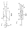
- FIG. 6 is a block diagram of an optical subsystem 130.
- the optical subsystem 130 includes, but is not necessarily limited to, a half-wave plate 132 and a Wollaston prism 136 configured to produce a first transmission beam 140 and a second transmission beam 142 based on a beam incident on the half-wave plate 132, such as the pulsed laser beam 18.
- the optical subsystem 130 provides two beams (e.g., the transmission beams 140 and 142) from a single beam (e.g., the pulsed laser beam 18), which may then be scanned, such as using the scanner 20 shown in FIG. 1 .
- a Wollaston prism manipulates polarized light by separating randomly polarized or unpolarized light into two orthogonal, linearly polarized outgoing beams.
- the Wollaston prism includes two calcite prisms that are coupled together to form two right trianglular prisms with orthogonal optical axes. Outgoing light beams diverge from the Wollaston prism resulting in the two differently polarized beams, with the angle of divergence determined by the prisms' wedge angle and the wavelength of the light.
- a first prism e.g., the first of the two coupled prisms encountered along the propagation direction
- an ordinary beam (O) and an extraordinary beam (A) are refracted in a first prism
- these two beams continue to propagate in the same direction.
- the ordinary beam (O) becomes an extraordinary beam at the boundary surface (e.g., between the two prisms).
- the half-wave plate 132 changes the polarization direction of light incident on the half-wave plate 132 (e.g., the pulsed laser beam 18).
- the linear polarized light is rotated to produce a first beam 134.
- the first transmission beam 140 e.g., linearly polarized along the plane of FIG. 6
- the second transmission beam 142 e.g., linearly polarized in/out of the plane of FIG. 6
- Each of the transmission beams 140 and 142 has an intensity associated therewith, I 1 and I 2 , respectively, and the intensity ratio of I 1 ,/I 2 can be continuously adjusted by the half-wave plate 132 (e.g., to provide a substantially unity ratio).
- FIG. 7 is a block diagram of an optical subsystem 150.
- the optical subsystem 150 includes tandem Wollaston prisms 152 and 158 to provide four beams (e.g., a first transmission beam 160, a second transmission beam 162, a third transmission beam 164, and a fourth transmission beam 166) from a single beam (e.g., the pulsed laser beam 18), which may then be scanned, such as using the scanner 20 shown in FIG. 1 .
- a first Wollaston prism 152 has orthogonal optical axes
- a second Wollaston prism 158 has optical axes that are orthogonal to one another and together rotated about 45° from the optical axes of the first Wollaston prism 152.
- the first Wollaston prism 152 receives the pulsed laser beam 18 and produces a first intermediate beam 154 having a first polarization and a second intermediate beam 156 having a second polarization orthogonal to the first polarization.
- the second Wollaston prism 158 produces the first and second transmission beam 160 and 162, respectively, from the first intermediate beam 154 and the third and fourth transmission beam 164 and 166, respectively, from the second intermediate beam 156.
- the first and second transmission beams 160 and 162 have orthogonal polarizations
- the third and forth transmission beams 164 and 166 have orthogonal polarizations.
- FIG. 8 is a top view of raster scan patterns 170, 180 formed on a material (e.g., glass).
- the pulsed laser beam 18 may be directed (e.g., without producing multiple beams by the optical subsystem 32) to the scanner 20 to produce the raster scan pattern 170.
- the raster scan pattern 170 has multiple raster lines 172, 174, 176, each corresponding to a different scan line, and each raster line 172, 174, 176 is formed from multiple spots.
- the raster scan pattern 170 was formed in glass with a 60 kHz laser and has a spot separation of about 7 ⁇ m (i.e., between adjacent spots along a raster line) and a scan line separation of about 14 ⁇ m (i.e., between adjacent raster lines).
- the raster scan pattern 180 has multiple pairs of raster lines, such as a first pair of raster lines 182 and 183, a second pair of raster lines 184 and 185, and a third pair of raster lines 186 and 187, and each raster line 182, 183, 184, 185, 186, and 187 is formed from multiple spots.
- Each of the pairs of raster lines 182 and 183, 184 and 185, 186 and 187 corresponds to a different scan line.
- the scanner 20 scans along a first scan line (Si) to produce the first pair of raster lines 182 and 183, along a second scan line (S 2 ) to produce the second pair of raster lines 184 and 185, and along a third scan line (S 3 ) to produce the third pair of raster lines 186 and 187.
- the raster scan pattern 180 was also formed in glass with the 60 kHz laser and has a spot separation of about 7 ⁇ m (i.e., between adjacent spots along a raster line) and a scan line separation of about 14 ⁇ m (i.e., between the adjacent scan lines).
- the optical subsystem 32 to produce the multiple beams 36 effectively doubles the scan spots and/or the raster lines while scanning at the same rate in comparison to scanning with the pulsed laser beam 18 to produce the raster scan pattern 170.
- the scan spots within a desired scan region can be increased without incurring additional scan time using the optical subsystem 32.
- the total scan time can be decreased using the optical subsystem 32.
- the optical subsystem 32 may also be configured to dynamically modify the pulsed laser beam 18 to produce the multiple beams 36.
- FIG. 9 is a side view of an optical subsystem 190 in accordance with the present invention, illustrating an "ON" configuration.
- FIG. 10 is a side view of the optical subsystem 190 shown in FIG. 9 illustrating an "OFF" configuration.
- the optical subsystem 190 may be implemented with the system 10 (e.g., substituted for the optical subsystem 32) and includes a first phase grating 191 substantially adjacent to a second phase grating 192.
- Each of the phase gratings 191, 192 has grooves 193 and 194, respectively, with a periodicity based on the wavelength of the pulsed laser beam 18.
- the grooves 193 of the first phase grating 191 face the grooves 194 of the second phase grating 192.
- the grooves 193 are aligned with the grooves 194 to phase shift the pulsed laser beam 18 and thereby produce multiple beams, such as the beams 44 and 46 shown in FIG. 2 .
- the grooves 193 are staggered with respect to the grooves 194 to shift light associated with each of the grooves 193, 194 by about a half period and thereby prevent the production of multiple beams.
- phase gratings 191 and 192 may be positioned with respect to one another to produce multiple beams from the pulsed laser beam 18 (e.g., using the ON configuration) or to pass the pulsed laser beam 18 (e.g., using the OFF configuration).
- the phase gratings 191 and 192 may also be positioned, according to the present invention, between the ON and OFF configurations to create a compound phase pattern.
- system for and method of photoaltering a material with multiple pulsed laser beams originating from a single input pulsed laser beam are disclosed.
- the system and method are suited to remove material, photoalter corneal tissue (not covered by the present invention) micromachine materials, surface profile various biological tissues, or the like.
- the optical subsystem 32 is simple to implement and integrate within the system 10 and improves the effective repetition rate of the pulsed laser beam by at least a factor of 2, 3, or greater.
- the optical subsystem 32 is used in the system 10, at least one of the following advantages may result: the overall procedure time associated with scanning is decreased, the energy associated with each scan spot is decreased, the relative smoothness of the scan bed is improved, and the scanning speed of the galvo is reduced.
Landscapes
- Optics & Photonics (AREA)
- Physics & Mathematics (AREA)
- Engineering & Computer Science (AREA)
- Health & Medical Sciences (AREA)
- Ophthalmology & Optometry (AREA)
- Plasma & Fusion (AREA)
- Mechanical Engineering (AREA)
- Biomedical Technology (AREA)
- Nuclear Medicine, Radiotherapy & Molecular Imaging (AREA)
- Surgery (AREA)
- Heart & Thoracic Surgery (AREA)
- Vascular Medicine (AREA)
- Life Sciences & Earth Sciences (AREA)
- Animal Behavior & Ethology (AREA)
- General Health & Medical Sciences (AREA)
- Public Health (AREA)
- Veterinary Medicine (AREA)
- Transplantation (AREA)
- Laser Beam Processing (AREA)
- Optical Recording Or Reproduction (AREA)
Description
- The field of the present invention is generally related to photoaltering materials and more particularly, to a system for and a method of photoaltering a natural according to the preamble of
claims 1 and 6 respectively (see, for example,EP 1 271 219 A - Pulsed laser beams include bursts or pulses of light, as implied by name, and have been used for photoalteration of materials, both inorganic and organic alike. Typically, a pulsed laser beam is focused onto a desired area of the material to photoalter the material in this area and, in some instances, the associated peripheral area. Examples of photoalteration of the material include, but are not necessarily limited to, chemical and physical alterations, chemical and physical breakdown, disintegration, ablation, vaporization, or the like.
- One example of photoalteration using pulsed laser beams is the photodisruption (e.g., via laser induced optical breakdown) of a material. Localized photodisruptions can be placed at or below the surface of the material to produce high-precision material processing. For example, a micro-optics scanning system may be used to scan the pulsed laser beams to produce an incision in the material and create a flap therefrom. The term "scan" or "scanning" refers to the movement of the focal point of the pulsed laser beam along a desired path or in a desired pattern. To create a flap of the material, the pulsed laser beam is typically scanned along a region within the material at a pre-determined scan rate and with a pre-determined focal spot size.
- For many applications, minimizing the scan time associated with photoalteration is generally desirable to expedite the overall procedure time. The repetition rate of the laser may be increased to generally decrease the scan time (e.g., for forming an incision in the material). In some laser systems, the repetition rate is typically limited by operating constraints of the amplifier or other components of the system. A simple increase in repetition rate may also affect other characteristics of the pulsed laser beam. For example, the pulse wavelength, the pulse duration, and the pulse intensity are inter-related. More specifically, the pulse intensity is proportional to the pulse energy and inversely proportional to the pulse duration, and the pulse energy is inversely proportional to the pulse wavelength.
- Accordingly, it is desirable to provide a system and method for photoaltering a material that increases the effective repetition rate of the pulsed laser beam. It is also desirable to provide a system and method for photoaltering a material with a pulsed laser beam that improves dissection quality and while reducing scanning speed associated with the photoalteration. Additionally, other desirable features and characteristics of the present invention will become apparent from the subsequent detailed description and the appended claims, taken in conjunction with the accompanying drawings and the foregoing technical field and background.
-
EP 1 271 219 A1 describes a laser beam delivery system that is able to separate a single laser beam into a plurality of equally sized and shaped laser beams. The laser beams are directed by a laser towards a rear surface of a computer-generated hologram. The equally sized and shaped laser beams exit the hologram on its rear surface. A pair of repeat positioners are provided for redirecting the equally sized and shaped collimated beams. - The present invention is directed towards photoaltering a material using a pulsed laser beam. In one embodiment, a system for photoaltering a material is defined in
claim 1. The system includes a laser source operable to produce a primary pulsed beam, a holographic optical element configured to receive the primary pulsed beam and transmit a plurality of secondary beams, and a scanner operable to direct the plurality of secondary beams to the material. The plurality of secondary beams is based on the primary pulsed beam. The primary pulsed beam has a first intensity. The holographic optical element is further configured to transmit a first secondary beam and a second secondary beam, in which the first secondary beam has a second intensity and the second secondary beam has a third intensity. A sum of the second and third intensities is greater than about 80% of the first intensity. - The present invention further relates to a method of photoaltering a material as defined in claim 6. The method includes phase shifting a pulsed laser beam to produce an input beam, holographically altering the input beam to produce a plurality of transmission beams, providing the input beam with a first intensity, providing a first transmission beam with a second intensity and a second transmission beam with a third intensity, wherein a sum of the second and third intensities is greater than about 80% of the first intensity, and scanning a portion of the material with the plurality of transmission beams.
- To enable a better understanding of the present invention, and to show how the same may be carried into effect, reference will now be made, by way of example only, to the accompanying drawings, wherein like reference numerals refer to similar components in which:
-
FIG. 1 is a block diagram of a laser scanner system; -
FIG. 2 is an elevational view of a holographic optical element; -
FIG. 3 is a block diagram of an optical subsystem; -
FIG. 4 is a block diagram of an optical subsystem; -
FIG. 5 is a block diagram of an optical subsystem; -
FIG. 6 is a block diagram of an optical subsystem; -
FIG. 7 is a block diagram of an optical subsystem; -
FIG. 8 is a top view of raster patterns formed in a material; -
FIG. 9 is a side view of an optical subsystem in accordance with one embodiment of the present invention illustrating an "ON" configuration; and -
FIG. 10 is a side view of the optical subsystem shown inFIG. 9 illustrating an "OFF" configuration. - The present invention provides a system and method for photoaltering a material with multiple beam scanning. Photoalteration of a material may be accomplished using a pulsed laser beam that is directed (e.g., via a scanner) at a desired region of the material. For example, a pulsed laser beam may be controlled to scan the desired region and to create a separation of the material (e.g., which may be used to produce a flap of the material, to separate a portion of the material for transplants, or for a variety of other uses). With the systems and methods of the present invention, multiple output laser beams are optically derived from a single input laser beam, and these output laser beams are simultaneously scanned in the desired region. In one embodiment, the input laser beam is converted to multiple laser beams using a holographic optical element, and the multiple beams are then scanned in the desired region of the material. The term "holographic optical element" (HOE) is defined herein to be an optical element that controls the production of a plurality of beams from a source beam via diffraction. The multiple beams may be produced from the single input laser beam using phase-based optical subsystems.
- Referring to the drawings, a
system 10 for photoaltering amaterial 12 is shown inFIG. 1 . Thesystem 10 includes, but is not necessarily limited to alaser source 14 capable of generating apulsed laser beam 18, anenergy control module 16 for varying the pulse energy of thepulsed laser beam 18, anoptical subsystem 32 for selectively converting thepulsed laser beam 18 to a plurality of beams 36 (e.g., multiple pulsed laser beams), ascanner 20, acontroller 22, and focusingoptics 28 that direct one or morefocal points 30 of thepulsed laser beam 18 or thebeams 36 onto the surface of or within the material 12 (e.g., sub-surface). The controller 22 (e.g., a processor operating suitable control software) communicates with one or more of thescanner 20,optical subsystem 32, and focusingoptics 28 to control the direction of thefocal point 30 as it is scanned along the material. In one scanning configuration, theoptical subsystem 32 converts thepulsed laser beam 18 to the plurality ofbeams 36 which is then provided to thescanner 20. In another scanning configuration, thepulsed laser beam 18 passes through theoptical subsystem 32 to thescanner 20. Thesystem 10 may switch between these scanning configurations (e.g., by manual selection, automatic selection in response to a programmed scanning procedure, any combination of manual and automatic selection, or other selection). - The
optical subsystem 32 is manually inserted into or removed from the propagation path of thepulsed laser beam 18 to thescanner 20 to receive thepulsed laser beam 18. In another embodiment, theoptical subsystem 32 is mechanically guided into the propagation path to capture thepulsed laser beam 18. Control signals may be automatically transmitted to the controller 22 (e.g., during execution of one or more programmed scanning procedures) or user input provided to thecontroller 22, which then actuates a servo component (not shown) coupled to theoptical subsystem 32. Various combinations of automated and manual control of theoptical subsystem 32 or other mechanisms may also be used to selectively produce thebeams 36 from thepulsed laser beam 18 via theoptical subsystem 32. In operation, thesystem 10 may have multiple scanning modes with at least one of the scanning modes engaging theoptical subsystem 32 to produce thebeams 36 when selected. The selective conversion of thepulsed laser beam 18 to thebeams 36 using theoptical subsystem 32 may thus be implemented in a variety of embodiments. - To impart at least a portion of the system control, software, firmware, or the like, can be used to command the actions and placement of the scanner via a motion control system, such as a closed-loop proportional integral derivative (PID) control system. In this case,. The
system 10 further includes abeam splitter 26 and adetector 24 coupled to thecontroller 22 to provide a feedback control mechanism for thepulsed laser beam 18 or thebeams 36. Thebeam splitter 26 anddetector 24 may also be omitted in other embodiments, for example, with different control mechanisms. - The
controller 22 includes computer hardware and/or software, often including one or more programmable processor unit running machine readable program instructions or code for implementing some or all of one or more of the methods described herein. The code is often embodied in a tangible media such as a memory (optionally a read only memory, a random access memory, a non-volatile memory, or the like) and/or a recording media (such as a floppy disk, a hard drive, a CD, a DVD, a memory stick, or the like). The code and/or associated data and signals may also be transmitted to or from the processor via a network connection (such as a wireless network, an Ethernet, an internet, an intranet, or the like), and some or all of the code may also be transmitted between components of thesystem 10 and within the controller via one or more bus, and appropriate standard or proprietary communications cards, connectors, cables, and the like will often be included in the controller. Thecontroller 22 is often configured to perform the calculations and signal transmission steps described herein at least in part by programming the controller with the software code, which may be written as a single program, a series of separate subroutines or related programs, or the like. Thecontroller 22 may include standard or proprietary digital and/or analog signal processing hardware, software, and/or firmware, and will typically have sufficient processing power to perform the calculations described herein during treatment. Thecontroller 22 optionally includes a personal computer, a notebook computer, a tablet computer, a proprietary processing unit, or a combination thereof. Standard or proprietary input devices (such as a mouse, keyboard, touchscreen, joystick, etc.) and output devices (such as a printer, speakers, display, etc.) associated with modern computer systems may also be included, and processors having a plurality of processing units (or even separate computers) may be employed in a wide range of centralized or distributed data processing architectures. - Movement of the focal point(s) 30 of the
pulsed laser beam 18 orbeams 36 is accomplished via thescanner 20 in response to thecontroller 22. In one case, thescanner 20 scans thepulsed laser beam 18 or thebeams 36 to produce an incision in the material. For a pre-determined scan rate, scanning thebeams 36 to produce an incision reduces the overall scan time in comparison with scanning the singlepulsed laser beam 18 to produce a substantially similar incision. For example, for a pre-determined scan spot distribution (e.g., as a result of scanning thebeam 18 in a pre-determined area), a similar scan spot distribution can be more rapidly produced by scanning thebeams 36 in the same area. When theoptical subsystem 32 outputs thebeams 36, thebeams 36 are simultaneously scanned to more rapidly produce a similar distribution of scan spots. - To provide the
pulsed laser beam 18, a chirped pulse laser amplification system, such as described inU.S. Pat. No. RE37,585 , may be used for photoalteration.U.S. Pat. Publication No. 2004/0243111 also describes other methods of photoalteration. Other devices or systems may be used to generate pulsed laser beams. For example, non-ultraviolet (UV), ultrashort pulsed laser technology can produce pulsed laser beams having pulse durations measured in femtoseconds. Some of the non-UV, ultrashort pulsed laser technology may be used in ophthalmic applications. For example,U.S. Pat. No. 5,993,438 discloses a device for performing ophthalmic surgical procedures to effect high-accuracy corrections of optical aberrations.U.S. Pat. No. 5,993,438 discloses an intrastromal photodisruption technique for reshaping the cornea using a non-UV, ultrashort (e.g., femtosecond pulse duration), pulsed laser beam that propagates through corneal tissue and is focused at a point below the surface of the cornea to photodisrupt stromal tissue at the focal point. Thepulsed laser beam 18 is preferably linearly polarized, but may be configured in a different polarization state (e.g., circularly polarized). - Although the
system 10 may be used to photoalter a variety of materials (e.g., organic, inorganic, or a combination thereof), thesystem 10 is suitable for ophthalmic applications. In this case, the focusingoptics 28 direct thepulsed laser beam 18 toward an eye (e.g., onto a cornea) for plasma mediated (e.g., non-UV) photoablation of superficial tissue, or into the stroma for intrastromal photodisruption of tissue. In this case, thesystem 10 may also include an applanation lens (not shown) to flatten the cornea prior to scanning thepulsed laser beam 18 toward the eye. A curved, or non-planar, lens may be substituted for the applanation lens to contact the cornea in other embodiments. - The
system 10 is capable of generating thepulsed laser beam 18 with physical characteristics similar to those of the laser beams generated by a laser system disclosed inU.S. Pat. No. 4,764,930 ,U.S. Pat. No. 5,993,438 , or the like. For example, thesystem 10 can produce a non-UV, ultrashort pulsed laser beam for use as an incising laser beam. This pulsed laser beam preferably has laser pulses with durations as long as a few nanoseconds or as short as a few femtoseconds. For intrastromal photodisruption of the tissue, thepulsed laser beam 18 has a wavelength that permits thepulsed laser beam 18 to pass through the cornea without absorption by the corneal tissue. The wavelength of thepulsed laser beam 18 is generally in the range of about 3 µm to about 1.9 nm, and preferably between about 400 nm to about 3000 nm. For accomplishing photodisruption of stromal tissues at the focal point, the irradiance of thepulsed laser beam 18 is preferably greater than the threshold for optical breakdown of the tissue. Although a non-UV, ultrashort pulsed laser beam is described in this embodiment, thepulsed laser beam 18 may have other pulse durations and different wavelengths in other embodiments. - Scanning is accomplished with the
scanner 20 via thecontroller 22 by selectively moving the focal point(s) 30 to produce a structured scan pattern (e.g., a raster pattern, a spiral pattern, or the like) of scan spots. Operating thescanner 20 to scan this structured pattern is particularly useful for controlling the spacing between scan spots of the pattern. The step rate at which thefocal point 30 is moved is referred to herein as the scan rate. For example, thescanner 20 can operate at scan rates between about 10 kHz and about 400 kHz, or at any other desired scan rate. In one embodiment, thescanner 20 generally moves the focal point of thepulsed laser beam 18 through the desired scan pattern at a substantially constant scan rate while maintaining a substantially constant separation between adjacent focal points. Further details of laser scanners are known in the art, such as described, for example, inU.S. Patent No. 5,549,632 , the entire disclosure of which is incorporated herein by reference. - In one case, the
scanner 20 includes, but is not necessarily limited to, a pair of scanning mirrors or other optics (not shown) to angularly deflect and scan one or more input beams (e.g, thepulsed laser beam 18 or beams 36). For example, scanning mirrors driven by galvanometers may be employed where each of the mirrors scans along different orthogonal axes (e.g., an x-axis and a y-axis). A focusing objective (not shown), having one or more lenses, images the input beam onto a focal plane of thesystem 10. Thefocal point 30 may thus be scanned in two dimensions (e.g., along the x-axis and the y-axis) within the focal plane of thesystem 10. Scanning along the third dimension, i.e., moving the focal plane along an optical axis (e.g., a z-axis), may be achieved by moving the focusing objective, or one or more lenses within the focusing objective, along the optical axis. - For ophthalmic applications, not covered by the present invention, (e.g., preparing a cornea for flap separation, corneal transplant, or the like), an area (e.g., substantially circular, oval, or other shape) may be scanned with a scan pattern based on the movement of the scanning mirrors. As the
focal point 30 is scanned along a corneal bed, thepulsed laser beam 18 orbeams 36 photoalter the stromal tissue. Using structured patterns, the distribution of scan spots is generally determined by the pulse frequency, the scan rate, the amount of scan line separation, and the number ofbeams - The
system 10 may additionally acquire detailed information about optical aberrations to be corrected, at least in part, using thesystem 10. Examples of such detailed information include, but are not necessarily limited to, the extent of the desired correction, and the location in the cornea of the eye associated with the correction (e.g., where the correction can be made most effectively). The refractive power of the cornea may be used to indicate corrections. Wavefront analysis techniques, made possible by devices such as a Hartmann-Shack type sensor (not shown), can be used to generate maps of corneal refractive power. Other wavefront analysis techniques and sensors may also be used. The maps of corneal refractive power, or similar refractive power information provided by other means, such as corneal topographs or the like, can then be used to identify and locate the optical aberrations of the cornea that require correction. - In general, when the
laser source 14 is activated, thefocal spot 30 is selectively directed (e.g., via the scanner 20) along a beam path to photoalter stromal tissue. For example, thefocal spot 30 is moved along a predetermined length of the beam path in one reference area. Thepulsed laser beam 18 orbeams 36 are then redirected through another reference area, and the process of photoalteration is repeated. The sequence for directing thepulsed laser beam 18 orbeams 36 through individually selected reference areas can be varied, and the extent of stromal tissue photoalteration while the incising laser beam is so directed, can be varied. Specifically, as indicated above, the amount of photoalteration can be based on the refractive power map. On the other hand, the sequence of reference areas that is followed during a customized procedure will depend on the particular objectives of the procedure. - The
scanner 20 may also scan a predetermined pattern using one or more scan patterns to one or more combinations of these reference areas or scan a single line (e.g., to produce a sidecut). One example of an ophthalmic scanning application is a laser assisted in-situ keratomilieusis (LASIK) type procedure where a flap is cut from the cornea to establish extracorporeal access to the tissue that is to be photoaltered. The flap may be created using random scanning or one or more scan patterns of pulsed laser beams. To create the corneal flap, a sidecut is created around a desired perimeter of the flap such that the ends of the sidecut terminate, without intersection, to leave an uncut segment. This uncut segment serves as a hinge for the flap. The flap is separated from the underlying stromal tissue by scanning the laser focal point across a resection bed, the perimeter of which is approximately defined by and slightly greater than the sidecut. Once this access has been achieved, photoalteration is completed, and the residual fragments of the photoaltered tissue are removed from the cornea, In another embodiment, the sidecut may be created completely around a desired perimeter (e.g., with the ends terminating with one another) to separate a portion of corneal tissue (e.g., for corneal transplant or the like) from the cornea. In another embodiment, intrastromal tissue may be photoaltered by thesystem 10 so as to create an isolated lenticle of intrastromal tissue. The lenticle of tissue can then be removed from the cornea. -
FIG. 2 is an elevational view of a holographicoptical element 42 in accordance with one embodiment. The holographicoptical element 42 may be used as theoptical subsystem 36, shown inFIG. 1 . Afirst transmission beam 44 and asecond transmission beam 46 are produced from an incident beam (i.e., the pulsed laser beam 18) on the holographicoptical element 42. In this embodiment, the phase shift between grating lines of the holographicoptical element 42 is about one-hundred and eighty degrees (180°) and results in secondary order diffracted beams from the incident beam while suppressing the zero order. The secondary order diffracted beams (e.g., the -1 and +1 order) have about eighty percent (80%) of the energy of the incident beam. Multi-level holographic optical elements can be produced which have lower losses (e.g., approaching about ninety-seven percent (97%) efficiency). The holographicoptical element 42 may be constructed to vary the angle of departure (i.e., from the angle of the incident beam) of the transmission beams 44, 46 as well as the number of output beams. - For example, each of the transmission beams 44, 46 may have a departure angle of about 0.25 rad from the incidence angle. In this example, the intensity (I1) associated with the
first transmission beam 44 is substantially similar to the intensity (I2) associated with the second transmission beam 46 (e.g., an average deviation from intensity symmetry of about 5%), and the average intensity associated with the transmission beams 44, 46 is greater than about 80% (e.g., (I1 + I2)/ I0) where I0 is the intensity associated with the pulsed laser beam 18). Total losses of the output beams 44, 46 in comparison with thepulsed laser beam 18 are less than about 200%. Thus, multiple beams are provided by the holographicoptical element 42 from thepulsed laser beam 18, which may then be scanned to form an incision. -
FIG. 3 is a block diagram of anoptical subsystem 50. Theoptical subsystem 50 includes, but is not necessarily limited to, a first quarter-wave plate 52, a firstpolarizing beam splitter 54, and an optics arrangement configured to produce afirst transmission beam 67 and asecond transmission beam 72 based on a beam incident on the quarter-wave plate 52, such as thepulsed laser beam 18. Thus, theoptical subsystem 50 provides two beams (e.g., the transmission beams 67 and 72) from a single beam (e.g., the pulsed laser beam 18), which may then be scanned, such as using thescanner 20 shown inFIG. 1 . - A wave plate or retarder is an optical device that alters the polarization state of an input light wave traveling therethrough. In one case, the wave plate operates by shifting the phase of the input light wave between two perpendicular polarization components. One example of a wave plate is a birefringent crystal having a a pre-determined thickness. This crystal is typically cut such that the extraordinary axis (i.e., polarized parallel to the axis of anisotropy) is parallel to the surfaces of the wave plate. When the extraordinary index is less than the ordinary (i.e., polarized perpendicularly to the axis of anisotropy) index, such as in calcite, the extraordinary axis is referred to as the "first axis," and the ordinary axis is referred to as the "slow axis." In general, light polarized along the first axis propagates faster than light polarized along the slow axis. Depending on the thickness of the crystal, input light with polarization components along both axes emerge from the crystal in a different polarization state.
- The wave plate is characterized by the amount of relative phase imparted on the two polarization components, which is related to the birefringence and the thickness of the crystal. For example, a quarter-wave plate creates a quarter wavelength phase shift and can change linearly polarized light to circular and vice versa (e.g., by adjusting the plane of the incident light to about a 45° angle with the fast axis). The resulting light has equal amplitude ordinary and extraordinary waves. A half-wave plate retards one polarization component by a half wavelength, or 180°, and thus rotates the polarization direction of linear polarized light.
- In operation, the quarter-
wave plate 52 converts thepulsed laser beam 18 from linear polarization to circular polarization, or more particularly, a circularly polarized pulsed laser beam. Thepolarizing beam splitter 54 receives the circularly polarized light and reflects light having one polarization (e.g., a first polarized beam 64) while transmitting light having a different polarization (e.g., a second polarized beam 68) than the reflected light. The first polarized beam 64 (e.g., linearly polarized along the plane ofFIG. 3 ) is reflected to a first optics group of the optics assembly, and the second polarized beam 68 (e.g., linearly polarized in/out of the plane ofFIG. 3 ) is transmitted to a second optics group of the optics assembly. - The first optics group includes a second quarter-
wave plate 56 and afirst mirror reflector 58. The firstpolarized beam 64 is incident on the quarter-wave plate 56, which converts the firstpolarized beam 64 to a circularly polarizedbeam 66, and themirror reflector 58 reflects the circularly polarizedbeam 66 back to the quarter-wave plate 56, which converts the circularly polarizedbeam 66 to thefirst transmission beam 67. Thefirst transmission beam 67 is linearly polarized orthogonal to the first polarized beam 64 (e.g., linearly polarized in/out of the plane ofFIG. 3 ) and is transmitted through thepolarizing beam splitter 54 to thescanner 20. - The second optics group includes a third quarter-
wave plate 60 and asecond mirror reflector 62 that is tiltable or may be pivoted. The secondpolarized beam 68 is incident on the quarter-wave plate 60, which converts the secondpolarized beam 68 to a circularly polarizedbeam 70, and themirror reflector 62 reflects the circularly polarizedbeam 70 back to the quarter-wave plate 60, which converts the circularly polarizedbeam 70 to thesecond transmission beam 72. Thesecond transmission beam 72 is linearly polarized orthogonal to the second polarized beam 68 (e.g., linearly polarized along the plane ofFIG. 3 ) and is reflected by thepolarizing beam splitter 54 to thescanner 20. Thefirst transmission beam 67 is angularly separated, and preferably divergent, from thesecond transmission beam 72 by the degree of tilt or pivot of thesecond mirror reflector 62, thereby controlling the separation between the focal points of the transmission beams 67, 72. -
FIG. 4 is a block diagram of anoptical subsystem 80. Theoptical subsystem 80 includes, but is not necessarily limited to, a firstpolarizing beam splitter 84, afirst mirror reflector 90 that is tillable or may be pivoted, asecond mirror reflector 94, and a secondpolarizing beam splitter 92. In one embodiment, abeam 82 incident on thepolarizing beam splitter 84, such as thepulsed laser beam 18, may have a polarization of about 45°±θ, where θ is selected for intensity ratio control. Thepolarizing beam splitters polarizing beam splitter 84 transmits a first polarized beam 86 (e.g., linearly polarized in/out of the plane ofFIG. 4 ) to themirror reflector 90 and reflects a second polarized beam 88 (e.g., linearly polarized along the plane ofFIG. 4 ) to themirror reflector 92. Both of thepolarized beams incident beam 82. Themirror reflector 90 reflects the firstpolarized beam 86 to thepolarizing beam splitter 92, and themirror reflector 94 reflects the secondpolarized beam 88 to thepolarizing beam splitter 92. Thepolarizing beam splitter 92 transmits the firstpolarized beam 86 and reflects the secondpolarized beam 88. Thus, theoptical subsystem 80 provides two beams (e.g., thepolarized beams 86 and 88) from a single beam (e.g., the pulsed laser beam 18), which may be provided to thescanner 20 shown inFIG. 1 . - The first
polarized beam 86 is angularly separated, and preferably divergent, from the secondpolarized beam 88 by the degree of tilt or pivot of themirror reflector 90, thereby controlling the separation between the focal points of thepolarized beams optical subsystem 80 generates two focal points (or two beams from a single beam), a different numbers of focal points (or multiple beams from a single beam) can be generated in other embodiments. For example, a tandem embodiment based on the optical subsystem 80 (e.g., series or parallel combinations of two of the optical subsystem 80) can be used to generate 4 focal points. -
FIG. 5 is a block diagram of anoptical subsystem 100. Theoptical subsystem 100 is based on a Fizeau wedge to produce two transmission beams from a single incident beam. A Fizeau wedge is generally formed by two optical elements at an angle to one another. Typically, an incident beam impinges on the front surface of the Fizeau wedge at an angle with the normal to the front surface. As this beam passes into the wedge, a portion of the incident beam is refracted as a second beam through the thickness of the wedge. The other portion of the incident beam not entering the wedge is reflected from the front surface. The second beam impinges on the internal side of the rear surface of the wedge and is reflected off the internal side of the rear surface towards the internal side of the front surface. Part of the reflected second beam exits the front surface of the wedge as a third beam. The other part of the reflected second beam is reflected back off the internal side of the front surface to the rear surface of the wedge as a fourth beam. - In this case, the
optical subsystem 100 includes, but is not necessarily limited to, anoptical element 102 and amirror reflector 108 oriented at a predetermined angle with respect to theoptical element 102. This angle may be adjusted depending on a desired focal point separation between at least two transmission beams. Theoptical element 102 has a predetermined reflectivity (R) that allows a majority of the incident light to pass through theoptical element 102. In one embodiment, the reflectivity is about 0.382 [R = (3/22)/2 = 0.382?], although theoptical element 102 may be configured with other values of reflectivity. - Based on this reflectivity, the
optical element 102 reflects a portion of a beam incident on the optical element 102 (e.g., the pulsed laser beam 18) and transmits another portion of thebeam 18. For example, theoptical element 102 reflects afirst beam 106 while reflecting asecond beam 104, where both the first andsecond beams beam 18. Themirror reflector 108 reflects thesecond beam 104 back to theoptical element 102, and theoptical element 102 transmits a portion of thesecond beam 104 while reflecting another portion of thesecond beam 104 based on the reflectivity, R. For example, theoptical element 102 transmits athird beam 109 while reflecting afourth beam 110, where both of thebeams second beam 104. This reflection bymirror reflector 108 and partial transmission and reflection byoptical element 102 can continue indefinitely. For example, themirror reflector 108 reflects thefourth beam 110 back to theoptical element 102. Based on the reflectivity, R, and thefourth beam 110, theoptical element 102 transmits afifth beam 112 while reflecting asixth beam 114. Themirror reflector 108 reflects thesixth beam 114 back to theoptical element 102. Based on the reflectivity, R, and thesixth beam 114, theoptical element 102 transmits aseventh beam 116 while reflecting aneighth beam 118. Themirror reflector 108 reflects theeighth beam 118 back to theoptical element 102. Based on the reflectivity, R, and theeighth beam 118, theoptical element 102 transmits aninth beam 120 while reflecting atenth beam 122. - In this case, the first and
third beams beams optical element 102 and themirror reflector 108. The beams other than the first andthird beams 106 and 109 (e.g., thebeams optical subsystem 100 have intensities (e.g., per pulse) that are substantially diminished from the intensities associated with each of the first andthird beams third beams fifth beam 112 may be represented by about 0.38 µJ, and the intensity of the seventh beam may be represented by about 0.147 µJ. The total percentage energy loss associated with thebeams third beams 106 and 109 (e.g., thebeams multiple beams pulsed laser beam 18 and can be directed to thescanner 20, shown inFIG. 1 . -
FIG. 6 is a block diagram of anoptical subsystem 130. Theoptical subsystem 130 includes, but is not necessarily limited to, a half-wave plate 132 and aWollaston prism 136 configured to produce afirst transmission beam 140 and asecond transmission beam 142 based on a beam incident on the half-wave plate 132, such as thepulsed laser beam 18. Thus, theoptical subsystem 130 provides two beams (e.g., the transmission beams 140 and 142) from a single beam (e.g., the pulsed laser beam 18), which may then be scanned, such as using thescanner 20 shown inFIG. 1 . - In general, a Wollaston prism manipulates polarized light by separating randomly polarized or unpolarized light into two orthogonal, linearly polarized outgoing beams. In one configuration, the Wollaston prism includes two calcite prisms that are coupled together to form two right trianglular prisms with orthogonal optical axes. Outgoing light beams diverge from the Wollaston prism resulting in the two differently polarized beams, with the angle of divergence determined by the prisms' wedge angle and the wavelength of the light. For example, light striking the surface of incidence at right angles is refracted in a first prism (e.g., the first of the two coupled prisms encountered along the propagation direction) into an ordinary beam (O) and an extraordinary beam (A). However, these two beams continue to propagate in the same direction. With the optical axis of the second prism being perpendicular to the optical axis of the first prism, the ordinary beam (O) becomes an extraordinary beam at the boundary surface (e.g., between the two prisms). The opposite applies to the original extraordinary beam (A), which becomes an ordinary beam.
- In this case, the half-
wave plate 132 changes the polarization direction of light incident on the half-wave plate 132 (e.g., the pulsed laser beam 18). By retarding one polarization component of thepulsed laser beam 18 by a half wavelength, the linear polarized light is rotated to produce afirst beam 134. At aboundary interface 138 of theWollaston prism 136, the first transmission beam 140 (e.g., linearly polarized along the plane ofFIG. 6 ) and the second transmission beam 142 (e.g., linearly polarized in/out of the plane ofFIG. 6 ) are produced from thefirst beam 134 and angularly separated by φ. In one embodiment, theWollaston prism 136 is constructed to produce an angle of separation φ = 6, although the angle of separation may vary in other embodiments. Each of the transmission beams 140 and 142 has an intensity associated therewith, I1 and I2, respectively, and the intensity ratio of I1,/I2 can be continuously adjusted by the half-wave plate 132 (e.g., to provide a substantially unity ratio). -
FIG. 7 is a block diagram of anoptical subsystem 150. Theoptical subsystem 150 includestandem Wollaston prisms first transmission beam 160, asecond transmission beam 162, athird transmission beam 164, and a fourth transmission beam 166) from a single beam (e.g., the pulsed laser beam 18), which may then be scanned, such as using thescanner 20 shown inFIG. 1 . In this embodiment, afirst Wollaston prism 152 has orthogonal optical axes, and asecond Wollaston prism 158 has optical axes that are orthogonal to one another and together rotated about 45° from the optical axes of thefirst Wollaston prism 152. In operation, thefirst Wollaston prism 152 receives thepulsed laser beam 18 and produces a firstintermediate beam 154 having a first polarization and a secondintermediate beam 156 having a second polarization orthogonal to the first polarization. Thesecond Wollaston prism 158 produces the first andsecond transmission beam intermediate beam 154 and the third andfourth transmission beam intermediate beam 156. The first and second transmission beams 160 and 162 have orthogonal polarizations, and the third and forth transmission beams 164 and 166 have orthogonal polarizations. -
FIG. 8 is a top view ofraster scan patterns 170, 180 formed on a material (e.g., glass). Referring toFIGS. 1 and8 , thepulsed laser beam 18 may be directed (e.g., without producing multiple beams by the optical subsystem 32) to thescanner 20 to produce theraster scan pattern 170. Theraster scan pattern 170 hasmultiple raster lines raster line raster scan pattern 170 was formed in glass with a 60 kHz laser and has a spot separation of about 7 µm (i.e., between adjacent spots along a raster line) and a scan line separation of about 14 µm (i.e., between adjacent raster lines). - When the
optical subsystem 32 produces themultiple beams 36 from thepulsed laser beam 18, thebeams 36 are directed to thescanner 20 to produce the raster scan pattern 180. The raster scan pattern 180 has multiple pairs of raster lines, such as a first pair ofraster lines 182 and 183, a second pair of raster lines 184 and 185, and a third pair of raster lines 186 and 187, and eachraster line 182, 183, 184, 185, 186, and 187 is formed from multiple spots. Each of the pairs ofraster lines 182 and 183, 184 and 185, 186 and 187 corresponds to a different scan line. For example, thescanner 20 scans along a first scan line (Si) to produce the first pair ofraster lines 182 and 183, along a second scan line (S2) to produce the second pair of raster lines 184 and 185, and along a third scan line (S3) to produce the third pair of raster lines 186 and 187. The raster scan pattern 180 was also formed in glass with the 60 kHz laser and has a spot separation of about 7 µm (i.e., between adjacent spots along a raster line) and a scan line separation of about 14 µm (i.e., between the adjacent scan lines). Using theoptical subsystem 32 to produce themultiple beams 36 effectively doubles the scan spots and/or the raster lines while scanning at the same rate in comparison to scanning with thepulsed laser beam 18 to produce theraster scan pattern 170. Thus, for a pre-determined scan rate, the scan spots within a desired scan region can be increased without incurring additional scan time using theoptical subsystem 32. Additionally, for a pre-determined scan rate and scan spot distribution, the total scan time can be decreased using theoptical subsystem 32. - The
optical subsystem 32 may also be configured to dynamically modify thepulsed laser beam 18 to produce the multiple beams 36.FIG. 9 is a side view of anoptical subsystem 190 in accordance with the present invention, illustrating an "ON" configuration.FIG. 10 is a side view of theoptical subsystem 190 shown inFIG. 9 illustrating an "OFF" configuration. Referring toFIGS. 1 ,9, and 10 , theoptical subsystem 190 may be implemented with the system 10 (e.g., substituted for the optical subsystem 32) and includes a first phase grating 191 substantially adjacent to a second phase grating 192. Each of thephase gratings grooves pulsed laser beam 18. Thegrooves 193 of the first phase grating 191 face thegrooves 194 of the second phase grating 192. In the ON configuration shown inFIG. 9 , thegrooves 193 are aligned with thegrooves 194 to phase shift thepulsed laser beam 18 and thereby produce multiple beams, such as thebeams FIG. 2 . In the OFF configuration, thegrooves 193 are staggered with respect to thegrooves 194 to shift light associated with each of thegrooves phase gratings phase gratings - Thus, system for and method of photoaltering a material with multiple pulsed laser beams originating from a single input pulsed laser beam are disclosed. The system and method are suited to remove material, photoalter corneal tissue (not covered by the present invention) micromachine materials, surface profile various biological tissues, or the like. The
optical subsystem 32 is simple to implement and integrate within thesystem 10 and improves the effective repetition rate of the pulsed laser beam by at least a factor of 2, 3, or greater. When theoptical subsystem 32 is used in thesystem 10, at least one of the following advantages may result: the overall procedure time associated with scanning is decreased, the energy associated with each scan spot is decreased, the relative smoothness of the scan bed is improved, and the scanning speed of the galvo is reduced. - While embodiments of this invention have been shown and described, it will be apparent to those skilled in the art that many more modifications are possible without departing from the inventive concepts as defined in the appended claims.
Claims (6)
- A system (10) for photoaltering a material (12), the system comprising:a laser source (14) operable to produce a primary pulsed beam (18);a holographic optical element (42) configured to receive the primary pulsed beam (18) and transmit a plurality of secondary beams (44, 46), the plurality of secondary beams (44, 46) based on the primary pulsed beam (18); anda scanner (20) operable to direct the plurality of secondary beams (44, 46) to the material (12),wherein the primary pulsed beam (18) has a first intensity (I0), wherein the holographic optical element (42) is further configured to transmit a first secondary beam (44) and a second secondary beam (46), the first secondary beam (44) having a second intensity (I1), the second secondary beam (46) having a third intensity (I2), and wherein a sum of the second (I1) and third (I2) intensities is greater than about 80% of the first intensity (I0),characterized in that the holographic optical element (42) comprises:a first phase grating (191) having a first surface and a second surface, the second surface of the first phase grating (191) opposing the first surface of the first phase grating (191), the first surface of the first phase grating (191) configured to receive the primary pulsed beam (18); anda second phase grating (192) having a first surface and a second surface, the second surface of the second phase grating (192) opposing the first surface of the second phase grating (192), the first surface of the second phase grating (192) adjacent to the second surface of the first phase grating (191), wherein the first phase grating (191) and the second phase grating (192) maybe positioned with respect to one another and the second surface of the second phase grating (192) configured to:transmit about 100% of the plurality of secondary beams (44, 46) when the first phase grating (191) and the second phase grating (192) are positioned in a first alignment;transmit about 0% of the plurality of secondary beams (44, 46) when the first phase grating (191) and the second phase grating (192) are positioned in a second alignment; andtransmit a variable portion of each of the plurality of secondary beams (44, 46) when the first phase grating (191) and the second phase grating (192) are positioned between the first alignment and the second alignment.
- The system (10) of claim 1, wherein the primary pulsed beam (18) has a first intensity (I0), wherein the holographic optical element (42) is further configured to transmit a first secondary beam (44) and a second secondary beam (46), the first secondary beam (44) having a second intensity (I1), the second secondary beam (46) having a third intensity (I2), and wherein a difference between the second intensity (I1) and the third intensity (I2) is less than about 5% of an average of the second (I1) and third (I2) intensities.
- The system (10) of claim 1, wherein the holographic optical element (42) is further configured to vary a spatial separation between each of the plurality of secondary beams (44, 46).
- The system (10) of claim 3, wherein the holographic optical element (42) has a transmission plane and an axis within the transmission plane, and wherein the holographic optical element (42) is configured to pivot the transmission plane about the axis.
- The system (10) of claim 1, wherein the system (10) has an optical axis extending between the holographic optical element (42) and the material (12), and wherein the holographic optical element (42) is further configured to rotate about the optical axis.
- A method of photoaltering a non-living material (12), the method comprising the steps of: producing an input beam (18) with a laser source (14);
holographically altering the input beam (18) to produce a plurality of transmission beams (44, 46);
providing the input beam (18) with a first intensity (I0);
providing a first transmission beam (44) with a second intensity (I1) and a second transmission beam (46) with a third intensity (I2), wherein a sum of the second (I1) and third (I2) intensities is greater than about 80% of the first intensity (I0); and
scanning a portion of the material (12) with the plurality of transmission beams (44, 46),
characterized in that the holographic optical element (42) comprises:a first phase grating (191) having a first surface and a second surface, the second surface of the first phase grating (191) opposing the first surface of the first phase grating (191), the first surface of the first phase grating (191) receiving the primary pulsed beam (18); anda second phase grating (192) having a first surface and a second surface, the second surface of the second phase grating (192) opposing the first surface of the second phase grating (192), the first surface of the second phase grating (192) adjacent to the second surface of the first phase grating (191), wherein the second surface of the second phase grating (192):transmits about 100% of the plurality of secondary beams (44, 46) when the first phase grating (191) and the second phase grating (192) are positioned in a first alignment;transmits about 0% of the plurality of secondary beams (44, 46) when the first phase grating (191) and the second phase grating (192) are positioned in a second alignment; andtransmits a variable portion of each of the plurality of secondary beams (44, 46) when the first phase grating (191) and the second phase grating (192) are positioned between the first alignment and the second alignment.
Applications Claiming Priority (2)
| Application Number | Priority Date | Filing Date | Title |
|---|---|---|---|
| US12/325,923 US8388609B2 (en) | 2008-12-01 | 2008-12-01 | System and method for multibeam scanning |
| PCT/US2009/066189 WO2010065498A2 (en) | 2008-12-01 | 2009-12-01 | System and method for multi-beam scanning |
Publications (2)
| Publication Number | Publication Date |
|---|---|
| EP2373454A2 EP2373454A2 (en) | 2011-10-12 |
| EP2373454B1 true EP2373454B1 (en) | 2015-04-22 |
Family
ID=41668475
Family Applications (1)
| Application Number | Title | Priority Date | Filing Date |
|---|---|---|---|
| EP09764673.1A Active EP2373454B1 (en) | 2008-12-01 | 2009-12-01 | Systems and method for laser photoaltering a material using multi-beam scanning |
Country Status (5)
| Country | Link |
|---|---|
| US (2) | US8388609B2 (en) |
| EP (1) | EP2373454B1 (en) |
| AU (1) | AU2009322589B2 (en) |
| CA (1) | CA2745296C (en) |
| WO (1) | WO2010065498A2 (en) |
Families Citing this family (32)
| Publication number | Priority date | Publication date | Assignee | Title |
|---|---|---|---|---|
| US9889043B2 (en) | 2006-01-20 | 2018-02-13 | Lensar, Inc. | System and apparatus for delivering a laser beam to the lens of an eye |
| US9545338B2 (en) | 2006-01-20 | 2017-01-17 | Lensar, Llc. | System and method for improving the accommodative amplitude and increasing the refractive power of the human lens with a laser |
| US10842675B2 (en) | 2006-01-20 | 2020-11-24 | Lensar, Inc. | System and method for treating the structure of the human lens with a laser |
| US8480659B2 (en) | 2008-07-25 | 2013-07-09 | Lensar, Inc. | Method and system for removal and replacement of lens material from the lens of an eye |
| US8500723B2 (en) | 2008-07-25 | 2013-08-06 | Lensar, Inc. | Liquid filled index matching device for ophthalmic laser procedures |
| EP2456384B1 (en) | 2009-07-24 | 2023-09-20 | LENSAR, Inc. | System for providing laser shot patterns to the lens of an eye |
| CN102639078B (en) | 2009-07-24 | 2015-10-21 | 能斯雅有限公司 | A system and method for performing lidar-assisted surgery on the lens of the eye |
| US8758332B2 (en) | 2009-07-24 | 2014-06-24 | Lensar, Inc. | Laser system and method for performing and sealing corneal incisions in the eye |
| US8382745B2 (en) | 2009-07-24 | 2013-02-26 | Lensar, Inc. | Laser system and method for astigmatic corrections in association with cataract treatment |
| US8617146B2 (en) | 2009-07-24 | 2013-12-31 | Lensar, Inc. | Laser system and method for correction of induced astigmatism |
| US8556425B2 (en) | 2010-02-01 | 2013-10-15 | Lensar, Inc. | Purkinjie image-based alignment of suction ring in ophthalmic applications |
| US8801186B2 (en) | 2010-10-15 | 2014-08-12 | Lensar, Inc. | System and method of scan controlled illumination of structures within an eye |
| USD694890S1 (en) | 2010-10-15 | 2013-12-03 | Lensar, Inc. | Laser system for treatment of the eye |
| USD695408S1 (en) | 2010-10-15 | 2013-12-10 | Lensar, Inc. | Laser system for treatment of the eye |
| US10463541B2 (en) | 2011-03-25 | 2019-11-05 | Lensar, Inc. | System and method for correcting astigmatism using multiple paired arcuate laser generated corneal incisions |
| CN103974678B (en) * | 2011-04-01 | 2017-02-08 | 雷萨公司 | Laser generated cornea and lens |
| EP2789059B1 (en) * | 2011-12-06 | 2018-12-05 | OFS Fitel, LLC | High-fidelity, high-energy ultrashort pulses from a net-normal-dispersion yb-fiber laser with an anomalous dispersion higher-order-mode fiber |
| JP6234296B2 (en) * | 2014-03-27 | 2017-11-22 | 住友重機械工業株式会社 | Laser processing apparatus and laser processing method |
| US10369663B1 (en) * | 2014-05-30 | 2019-08-06 | Gentex Corporation | Laser process with controlled polarization |
| FR3026940B1 (en) * | 2014-10-08 | 2021-09-03 | Univ Jean Monnet | DEVICE AND METHOD FOR CUTTING A HORN OR A CRYSTALLINE |
| JP6426443B2 (en) * | 2014-11-18 | 2018-11-21 | 株式会社ディスコ | Laser processing equipment |
| JP6430790B2 (en) * | 2014-11-25 | 2018-11-28 | 株式会社ディスコ | Laser processing equipment |
| FR3049847B1 (en) * | 2016-04-06 | 2022-06-10 | Keranova | PATTERN FOR CUTTING AN APPARATUS FOR CUTTING HUMAN OR ANIMAL TISSUE |
| PL3439594T3 (en) * | 2016-04-06 | 2021-12-20 | Keranova | Optical scanner for a human or animal tissue cutting device |
| FR3049853B1 (en) * | 2016-04-06 | 2018-04-27 | Keranova | OPTICAL SCANNER FOR SCANNING AN APPARATUS FOR CUTTING A HUMAN OR ANIMAL TISSUE |
| FR3049848B1 (en) * | 2016-04-06 | 2021-12-10 | Keranova | OPTICAL FOCUSING SYSTEM OF AN APPARATUS FOR CUTTING A HUMAN OR ANIMAL TISSUE |
| CA3060349A1 (en) | 2017-06-15 | 2018-12-20 | Alcon Inc. | Birefringent lens for laser beam delivery |
| CN113433710A (en) * | 2020-03-23 | 2021-09-24 | 广州印芯半导体技术有限公司 | Polarization beam splitting system |
| FR3115676B1 (en) | 2020-10-29 | 2022-12-16 | Keranova | SYSTEM FOR CUTTING OCULAR TISSUE INTO ELEMENTARY PORTIONS |
| DE102021106407A1 (en) | 2021-03-16 | 2022-09-22 | Carl Zeiss Meditec Ag | Beam splitting device, ophthalmic laser therapy system, method of scanning a patient's eye and method of splitting |
| FR3142882B1 (en) | 2022-12-12 | 2024-12-13 | Keranova | SYSTEM FOR CUTTING OCULAR TISSUE INTO ELEMENTARY PORTIONS |
| DE102024105034A1 (en) * | 2023-12-01 | 2025-06-05 | Carl Zeiss Meditec Ag | Ophthalmological laser therapy system and method, beam splitter for a laser therapy system, method and device for generating control data and software product for carrying out the said methods |
Family Cites Families (27)
| Publication number | Priority date | Publication date | Assignee | Title |
|---|---|---|---|---|
| JPS6011325B2 (en) * | 1977-01-21 | 1985-03-25 | キヤノン株式会社 | scanning device |
| DE3620744A1 (en) * | 1986-06-20 | 1987-12-23 | Rodenstock Instr | DEVICE FOR TREATING THE EYE WITH A LASER |
| US4764930A (en) * | 1988-01-27 | 1988-08-16 | Intelligent Surgical Lasers | Multiwavelength laser source |
| US5481384A (en) * | 1992-03-30 | 1996-01-02 | Holotek Ltd. | Deflector system which produces dual, oppositely directed scanning beams simultaneously or successively |
| US5549632A (en) * | 1992-10-26 | 1996-08-27 | Novatec Laser Systems, Inc. | Method and apparatus for ophthalmic surgery |
| US5993438A (en) * | 1993-11-12 | 1999-11-30 | Escalon Medical Corporation | Intrastromal photorefractive keratectomy |
| US5656186A (en) * | 1994-04-08 | 1997-08-12 | The Regents Of The University Of Michigan | Method for controlling configuration of laser induced breakdown and ablation |
| US5480396A (en) * | 1994-12-09 | 1996-01-02 | Simon; Gabriel | Laser beam ophthalmological surgery method and apparatus |
| US5599340A (en) * | 1994-12-09 | 1997-02-04 | Simon; Gabriel | Laser beam ophthalmological surgery method and apparatus |
| US6897957B2 (en) * | 2001-03-26 | 2005-05-24 | Candela Instruments | Material independent optical profilometer |
| US7714995B2 (en) * | 1997-09-22 | 2010-05-11 | Kla-Tencor Corporation | Material independent profiler |
| US6141826A (en) * | 1999-01-08 | 2000-11-07 | G.B.D. Corp. | Center air feed for cyclonic separator |
| JP4218209B2 (en) * | 1999-03-05 | 2009-02-04 | 三菱電機株式会社 | Laser processing equipment |
| US6538775B1 (en) * | 1999-09-16 | 2003-03-25 | Reveo, Inc. | Holographically-formed polymer dispersed liquid crystals with multiple gratings |
| EP1339522A1 (en) * | 2000-11-13 | 2003-09-03 | Micmacmo Aps | Laser ablation |
| US7345751B2 (en) * | 2001-03-26 | 2008-03-18 | Kla-Tencor Technologies Corporation | Material independent optical profilometer |
| US6804269B2 (en) | 2001-06-19 | 2004-10-12 | Hitachi Via Mechanics, Ltd. | Laser beam delivery system with trepanning module |
| US6610050B2 (en) * | 2001-07-27 | 2003-08-26 | 20/10 Perfect Vision, Optische Geraete Gmbh | Laser beam delivery system with multiple focal points |
| US6864478B2 (en) * | 2002-04-22 | 2005-03-08 | Visx, Incorporation | Beam position monitoring for laser eye surgery |
| US7351241B2 (en) * | 2003-06-02 | 2008-04-01 | Carl Zeiss Meditec Ag | Method and apparatus for precision working of material |
| US7633034B2 (en) * | 2004-06-18 | 2009-12-15 | Electro Scientific Industries, Inc. | Semiconductor structure processing using multiple laser beam spots overlapping lengthwise on a structure |
| US7116403B2 (en) * | 2004-06-28 | 2006-10-03 | Asml Netherlands B.V | Lithographic apparatus and device manufacturing method |
| US8382744B2 (en) * | 2006-08-23 | 2013-02-26 | Szymon Suckewer | Method and device for cornea reshaping by intrastromal tissue removal |
| US20080094711A1 (en) * | 2006-10-11 | 2008-04-24 | Oleg Efimov | Methods and apparatus for recording holographic gratings |
| ES2640088T3 (en) * | 2006-11-10 | 2017-10-31 | Topcon Medical Laser Systems Inc. | System to determine dosimetry in ophthalmic photo-medicine |
| US8568393B2 (en) * | 2007-03-13 | 2013-10-29 | Topcon Medical Laser Systems, Inc. | Computer guided patterned laser trabeculoplasty |
| JP5259154B2 (en) * | 2007-10-24 | 2013-08-07 | オリンパス株式会社 | Scanning laser microscope |
-
2008
- 2008-12-01 US US12/325,923 patent/US8388609B2/en active Active
-
2009
- 2009-12-01 EP EP09764673.1A patent/EP2373454B1/en active Active
- 2009-12-01 AU AU2009322589A patent/AU2009322589B2/en not_active Ceased
- 2009-12-01 CA CA2745296A patent/CA2745296C/en not_active Expired - Fee Related
- 2009-12-01 WO PCT/US2009/066189 patent/WO2010065498A2/en not_active Ceased
- 2009-12-18 US US12/641,493 patent/US20100331829A1/en not_active Abandoned
Also Published As
| Publication number | Publication date |
|---|---|
| WO2010065498A3 (en) | 2010-07-29 |
| US20100133246A1 (en) | 2010-06-03 |
| CA2745296C (en) | 2017-01-03 |
| US8388609B2 (en) | 2013-03-05 |
| AU2009322589A1 (en) | 2011-06-23 |
| CA2745296A1 (en) | 2010-06-10 |
| EP2373454A2 (en) | 2011-10-12 |
| AU2009322589B2 (en) | 2014-12-18 |
| WO2010065498A2 (en) | 2010-06-10 |
| US20100331829A1 (en) | 2010-12-30 |
Similar Documents
| Publication | Publication Date | Title |
|---|---|---|
| CA2745296C (en) | System and method for multi-beam scanning | |
| US10973684B2 (en) | Machining device and method | |
| JP4615735B2 (en) | Apparatus and method for ablating surfaces with partially overlapping craters with uniform curvature | |
| CA2904894C (en) | Free floating support for laser eye surgery system | |
| KR102499252B1 (en) | Beam multiplexers for writing refractive index changes into optical materials | |
| DK2976176T3 (en) | Method and apparatus for preparing a structure on the surfaces of components with a laser beam | |
| US20090118716A1 (en) | System and method for scanning a pulsed laser beam | |
| JP7455848B2 (en) | Calibration of the position of the laser beam focus | |
| CA2711879A1 (en) | Laser correction of vision conditions on the natural eye lens | |
| KR101624600B1 (en) | Laser-assisted epithelial removal | |
| WO2003068051A2 (en) | Flexible scanning beam imaging system | |
| AU2017202298B2 (en) | System and method for laser photoaltering a material using multi-beam scanning | |
| JP2024538244A (en) | Generating a bubble jet to break up and remove eye floaters | |
| US20230347171A1 (en) | Laser treatment apparatus | |
| US11738205B2 (en) | Laser treatment apparatus | |
| CA3125520C (en) | Calibrating the position of the focal point of a laser beam | |
| JP2024538228A (en) | Generating a bubble jet to break up and remove eye floaters |
Legal Events
| Date | Code | Title | Description |
|---|---|---|---|
| PUAI | Public reference made under article 153(3) epc to a published international application that has entered the european phase |
Free format text: ORIGINAL CODE: 0009012 |
|
| 17P | Request for examination filed |
Effective date: 20110531 |
|
| AK | Designated contracting states |
Kind code of ref document: A2 Designated state(s): AT BE BG CH CY CZ DE DK EE ES FI FR GB GR HR HU IE IS IT LI LT LU LV MC MK MT NL NO PL PT RO SE SI SK SM TR |
|
| DAX | Request for extension of the european patent (deleted) | ||
| GRAP | Despatch of communication of intention to grant a patent |
Free format text: ORIGINAL CODE: EPIDOSNIGR1 |
|
| INTG | Intention to grant announced |
Effective date: 20140701 |
|
| GRAP | Despatch of communication of intention to grant a patent |
Free format text: ORIGINAL CODE: EPIDOSNIGR1 |
|
| INTG | Intention to grant announced |
Effective date: 20140904 |
|
| GRAP | Despatch of communication of intention to grant a patent |
Free format text: ORIGINAL CODE: EPIDOSNIGR1 |
|
| INTG | Intention to grant announced |
Effective date: 20150121 |
|
| GRAS | Grant fee paid |
Free format text: ORIGINAL CODE: EPIDOSNIGR3 |
|
| GRAA | (expected) grant |
Free format text: ORIGINAL CODE: 0009210 |
|
| AK | Designated contracting states |
Kind code of ref document: B1 Designated state(s): AT BE BG CH CY CZ DE DK EE ES FI FR GB GR HR HU IE IS IT LI LT LU LV MC MK MT NL NO PL PT RO SE SI SK SM TR |
|
| REG | Reference to a national code |
Ref country code: GB Ref legal event code: FG4D |
|
| REG | Reference to a national code |
Ref country code: CH Ref legal event code: EP |
|
| REG | Reference to a national code |
Ref country code: AT Ref legal event code: REF Ref document number: 722916 Country of ref document: AT Kind code of ref document: T Effective date: 20150515 |
|
| REG | Reference to a national code |
Ref country code: IE Ref legal event code: FG4D |
|
| REG | Reference to a national code |
Ref country code: DE Ref legal event code: R096 Ref document number: 602009030808 Country of ref document: DE Effective date: 20150603 |
|
| REG | Reference to a national code |
Ref country code: NL Ref legal event code: T3 |
|
| REG | Reference to a national code |
Ref country code: AT Ref legal event code: MK05 Ref document number: 722916 Country of ref document: AT Kind code of ref document: T Effective date: 20150422 |
|
| REG | Reference to a national code |
Ref country code: LT Ref legal event code: MG4D |
|
| PG25 | Lapsed in a contracting state [announced via postgrant information from national office to epo] |
Ref country code: FI Free format text: LAPSE BECAUSE OF FAILURE TO SUBMIT A TRANSLATION OF THE DESCRIPTION OR TO PAY THE FEE WITHIN THE PRESCRIBED TIME-LIMIT Effective date: 20150422 Ref country code: HR Free format text: LAPSE BECAUSE OF FAILURE TO SUBMIT A TRANSLATION OF THE DESCRIPTION OR TO PAY THE FEE WITHIN THE PRESCRIBED TIME-LIMIT Effective date: 20150422 Ref country code: NO Free format text: LAPSE BECAUSE OF FAILURE TO SUBMIT A TRANSLATION OF THE DESCRIPTION OR TO PAY THE FEE WITHIN THE PRESCRIBED TIME-LIMIT Effective date: 20150722 Ref country code: LT Free format text: LAPSE BECAUSE OF FAILURE TO SUBMIT A TRANSLATION OF THE DESCRIPTION OR TO PAY THE FEE WITHIN THE PRESCRIBED TIME-LIMIT Effective date: 20150422 Ref country code: PT Free format text: LAPSE BECAUSE OF FAILURE TO SUBMIT A TRANSLATION OF THE DESCRIPTION OR TO PAY THE FEE WITHIN THE PRESCRIBED TIME-LIMIT Effective date: 20150824 Ref country code: ES Free format text: LAPSE BECAUSE OF FAILURE TO SUBMIT A TRANSLATION OF THE DESCRIPTION OR TO PAY THE FEE WITHIN THE PRESCRIBED TIME-LIMIT Effective date: 20150422 |
|
| REG | Reference to a national code |
Ref country code: FR Ref legal event code: PLFP Year of fee payment: 7 |
|
| PG25 | Lapsed in a contracting state [announced via postgrant information from national office to epo] |
Ref country code: LV Free format text: LAPSE BECAUSE OF FAILURE TO SUBMIT A TRANSLATION OF THE DESCRIPTION OR TO PAY THE FEE WITHIN THE PRESCRIBED TIME-LIMIT Effective date: 20150422 Ref country code: IS Free format text: LAPSE BECAUSE OF FAILURE TO SUBMIT A TRANSLATION OF THE DESCRIPTION OR TO PAY THE FEE WITHIN THE PRESCRIBED TIME-LIMIT Effective date: 20150822 Ref country code: AT Free format text: LAPSE BECAUSE OF FAILURE TO SUBMIT A TRANSLATION OF THE DESCRIPTION OR TO PAY THE FEE WITHIN THE PRESCRIBED TIME-LIMIT Effective date: 20150422 Ref country code: GR Free format text: LAPSE BECAUSE OF FAILURE TO SUBMIT A TRANSLATION OF THE DESCRIPTION OR TO PAY THE FEE WITHIN THE PRESCRIBED TIME-LIMIT Effective date: 20150723 |
|
| REG | Reference to a national code |
Ref country code: DE Ref legal event code: R097 Ref document number: 602009030808 Country of ref document: DE |
|
| PG25 | Lapsed in a contracting state [announced via postgrant information from national office to epo] |
Ref country code: EE Free format text: LAPSE BECAUSE OF FAILURE TO SUBMIT A TRANSLATION OF THE DESCRIPTION OR TO PAY THE FEE WITHIN THE PRESCRIBED TIME-LIMIT Effective date: 20150422 Ref country code: DK Free format text: LAPSE BECAUSE OF FAILURE TO SUBMIT A TRANSLATION OF THE DESCRIPTION OR TO PAY THE FEE WITHIN THE PRESCRIBED TIME-LIMIT Effective date: 20150422 |
|
| PLBE | No opposition filed within time limit |
Free format text: ORIGINAL CODE: 0009261 |
|
| STAA | Information on the status of an ep patent application or granted ep patent |
Free format text: STATUS: NO OPPOSITION FILED WITHIN TIME LIMIT |
|
| PG25 | Lapsed in a contracting state [announced via postgrant information from national office to epo] |
Ref country code: PL Free format text: LAPSE BECAUSE OF FAILURE TO SUBMIT A TRANSLATION OF THE DESCRIPTION OR TO PAY THE FEE WITHIN THE PRESCRIBED TIME-LIMIT Effective date: 20150422 Ref country code: RO Free format text: LAPSE BECAUSE OF NON-PAYMENT OF DUE FEES Effective date: 20150422 Ref country code: SK Free format text: LAPSE BECAUSE OF FAILURE TO SUBMIT A TRANSLATION OF THE DESCRIPTION OR TO PAY THE FEE WITHIN THE PRESCRIBED TIME-LIMIT Effective date: 20150422 Ref country code: CZ Free format text: LAPSE BECAUSE OF FAILURE TO SUBMIT A TRANSLATION OF THE DESCRIPTION OR TO PAY THE FEE WITHIN THE PRESCRIBED TIME-LIMIT Effective date: 20150422 |
|
| 26N | No opposition filed |
Effective date: 20160125 |
|
| PG25 | Lapsed in a contracting state [announced via postgrant information from national office to epo] |
Ref country code: IT Free format text: LAPSE BECAUSE OF FAILURE TO SUBMIT A TRANSLATION OF THE DESCRIPTION OR TO PAY THE FEE WITHIN THE PRESCRIBED TIME-LIMIT Effective date: 20150422 |
|
| PG25 | Lapsed in a contracting state [announced via postgrant information from national office to epo] |
Ref country code: BE Free format text: LAPSE BECAUSE OF NON-PAYMENT OF DUE FEES Effective date: 20151231 Ref country code: SI Free format text: LAPSE BECAUSE OF FAILURE TO SUBMIT A TRANSLATION OF THE DESCRIPTION OR TO PAY THE FEE WITHIN THE PRESCRIBED TIME-LIMIT Effective date: 20150422 |
|
| PG25 | Lapsed in a contracting state [announced via postgrant information from national office to epo] |
Ref country code: LU Free format text: LAPSE BECAUSE OF FAILURE TO SUBMIT A TRANSLATION OF THE DESCRIPTION OR TO PAY THE FEE WITHIN THE PRESCRIBED TIME-LIMIT Effective date: 20151201 Ref country code: MC Free format text: LAPSE BECAUSE OF FAILURE TO SUBMIT A TRANSLATION OF THE DESCRIPTION OR TO PAY THE FEE WITHIN THE PRESCRIBED TIME-LIMIT Effective date: 20150422 |
|
| PG25 | Lapsed in a contracting state [announced via postgrant information from national office to epo] |
Ref country code: BE Free format text: LAPSE BECAUSE OF FAILURE TO SUBMIT A TRANSLATION OF THE DESCRIPTION OR TO PAY THE FEE WITHIN THE PRESCRIBED TIME-LIMIT Effective date: 20150422 |
|
| REG | Reference to a national code |
Ref country code: IE Ref legal event code: MM4A |
|
| PG25 | Lapsed in a contracting state [announced via postgrant information from national office to epo] |
Ref country code: IE Free format text: LAPSE BECAUSE OF NON-PAYMENT OF DUE FEES Effective date: 20151201 |
|
| REG | Reference to a national code |
Ref country code: FR Ref legal event code: PLFP Year of fee payment: 8 |
|
| PG25 | Lapsed in a contracting state [announced via postgrant information from national office to epo] |
Ref country code: BG Free format text: LAPSE BECAUSE OF FAILURE TO SUBMIT A TRANSLATION OF THE DESCRIPTION OR TO PAY THE FEE WITHIN THE PRESCRIBED TIME-LIMIT Effective date: 20150422 Ref country code: SM Free format text: LAPSE BECAUSE OF FAILURE TO SUBMIT A TRANSLATION OF THE DESCRIPTION OR TO PAY THE FEE WITHIN THE PRESCRIBED TIME-LIMIT Effective date: 20150422 Ref country code: HU Free format text: LAPSE BECAUSE OF FAILURE TO SUBMIT A TRANSLATION OF THE DESCRIPTION OR TO PAY THE FEE WITHIN THE PRESCRIBED TIME-LIMIT; INVALID AB INITIO Effective date: 20091201 |
|
| PG25 | Lapsed in a contracting state [announced via postgrant information from national office to epo] |
Ref country code: CY Free format text: LAPSE BECAUSE OF FAILURE TO SUBMIT A TRANSLATION OF THE DESCRIPTION OR TO PAY THE FEE WITHIN THE PRESCRIBED TIME-LIMIT Effective date: 20150422 Ref country code: SE Free format text: LAPSE BECAUSE OF FAILURE TO SUBMIT A TRANSLATION OF THE DESCRIPTION OR TO PAY THE FEE WITHIN THE PRESCRIBED TIME-LIMIT Effective date: 20150422 |
|
| PG25 | Lapsed in a contracting state [announced via postgrant information from national office to epo] |
Ref country code: TR Free format text: LAPSE BECAUSE OF FAILURE TO SUBMIT A TRANSLATION OF THE DESCRIPTION OR TO PAY THE FEE WITHIN THE PRESCRIBED TIME-LIMIT Effective date: 20150422 Ref country code: MT Free format text: LAPSE BECAUSE OF FAILURE TO SUBMIT A TRANSLATION OF THE DESCRIPTION OR TO PAY THE FEE WITHIN THE PRESCRIBED TIME-LIMIT Effective date: 20150422 |
|
| REG | Reference to a national code |
Ref country code: FR Ref legal event code: PLFP Year of fee payment: 9 |
|
| REG | Reference to a national code |
Ref country code: CH Ref legal event code: NV Representative=s name: E. BLUM AND CO. AG PATENT- UND MARKENANWAELTE , CH |
|
| PG25 | Lapsed in a contracting state [announced via postgrant information from national office to epo] |
Ref country code: MK Free format text: LAPSE BECAUSE OF FAILURE TO SUBMIT A TRANSLATION OF THE DESCRIPTION OR TO PAY THE FEE WITHIN THE PRESCRIBED TIME-LIMIT Effective date: 20150422 |
|
| PGFP | Annual fee paid to national office [announced via postgrant information from national office to epo] |
Ref country code: NL Payment date: 20181114 Year of fee payment: 10 |
|
| PGFP | Annual fee paid to national office [announced via postgrant information from national office to epo] |
Ref country code: GB Payment date: 20181128 Year of fee payment: 10 Ref country code: FR Payment date: 20181123 Year of fee payment: 10 Ref country code: CH Payment date: 20181217 Year of fee payment: 10 |
|
| REG | Reference to a national code |
Ref country code: CH Ref legal event code: PL |
|
| REG | Reference to a national code |
Ref country code: NL Ref legal event code: MM Effective date: 20200101 |
|
| GBPC | Gb: european patent ceased through non-payment of renewal fee |
Effective date: 20191201 |
|
| PG25 | Lapsed in a contracting state [announced via postgrant information from national office to epo] |
Ref country code: NL Free format text: LAPSE BECAUSE OF NON-PAYMENT OF DUE FEES Effective date: 20200101 |
|
| PG25 | Lapsed in a contracting state [announced via postgrant information from national office to epo] |
Ref country code: FR Free format text: LAPSE BECAUSE OF NON-PAYMENT OF DUE FEES Effective date: 20191231 Ref country code: GB Free format text: LAPSE BECAUSE OF NON-PAYMENT OF DUE FEES Effective date: 20191201 |
|
| PG25 | Lapsed in a contracting state [announced via postgrant information from national office to epo] |
Ref country code: CH Free format text: LAPSE BECAUSE OF NON-PAYMENT OF DUE FEES Effective date: 20191231 Ref country code: LI Free format text: LAPSE BECAUSE OF NON-PAYMENT OF DUE FEES Effective date: 20191231 |
|
| PGFP | Annual fee paid to national office [announced via postgrant information from national office to epo] |
Ref country code: DE Payment date: 20241029 Year of fee payment: 16 |