EP2373235B1 - Force sensing distal femoral alignment system - Google Patents
Force sensing distal femoral alignment system Download PDFInfo
- Publication number
- EP2373235B1 EP2373235B1 EP09824192.0A EP09824192A EP2373235B1 EP 2373235 B1 EP2373235 B1 EP 2373235B1 EP 09824192 A EP09824192 A EP 09824192A EP 2373235 B1 EP2373235 B1 EP 2373235B1
- Authority
- EP
- European Patent Office
- Prior art keywords
- femoral
- knee
- medial
- adjustable
- lateral
- Prior art date
- Legal status (The legal status is an assumption and is not a legal conclusion. Google has not performed a legal analysis and makes no representation as to the accuracy of the status listed.)
- Not-in-force
Links
- 210000003127 knee Anatomy 0.000 claims description 168
- 210000000689 upper leg Anatomy 0.000 claims description 99
- 210000000988 bone and bone Anatomy 0.000 claims description 34
- 210000002303 tibia Anatomy 0.000 claims description 34
- 238000012795 verification Methods 0.000 claims description 34
- 238000005520 cutting process Methods 0.000 claims description 28
- 238000001356 surgical procedure Methods 0.000 claims description 28
- 230000000007 visual effect Effects 0.000 claims description 12
- 239000003990 capacitor Substances 0.000 claims description 2
- 238000012790 confirmation Methods 0.000 claims description 2
- 238000012545 processing Methods 0.000 claims description 2
- 238000000034 method Methods 0.000 description 28
- 238000013150 knee replacement Methods 0.000 description 16
- 210000002414 leg Anatomy 0.000 description 11
- 238000002271 resection Methods 0.000 description 8
- 210000004872 soft tissue Anatomy 0.000 description 7
- 238000005516 engineering process Methods 0.000 description 6
- 210000003041 ligament Anatomy 0.000 description 6
- 230000008878 coupling Effects 0.000 description 5
- 238000010168 coupling process Methods 0.000 description 5
- 238000005859 coupling reaction Methods 0.000 description 5
- 210000000629 knee joint Anatomy 0.000 description 5
- 210000004417 patella Anatomy 0.000 description 5
- 238000002595 magnetic resonance imaging Methods 0.000 description 4
- 230000000712 assembly Effects 0.000 description 3
- 238000000429 assembly Methods 0.000 description 3
- 210000004439 collateral ligament Anatomy 0.000 description 3
- 239000013589 supplement Substances 0.000 description 3
- 238000011883 total knee arthroplasty Methods 0.000 description 3
- 0 C1C**CC1 Chemical compound C1C**CC1 0.000 description 2
- 238000011882 arthroplasty Methods 0.000 description 2
- 238000002591 computed tomography Methods 0.000 description 2
- 239000007943 implant Substances 0.000 description 2
- 230000005499 meniscus Effects 0.000 description 2
- 125000006850 spacer group Chemical group 0.000 description 2
- 208000006820 Arthralgia Diseases 0.000 description 1
- 208000002193 Pain Diseases 0.000 description 1
- 210000003484 anatomy Anatomy 0.000 description 1
- 210000001264 anterior cruciate ligament Anatomy 0.000 description 1
- 230000002917 arthritic effect Effects 0.000 description 1
- 239000002775 capsule Substances 0.000 description 1
- 210000000845 cartilage Anatomy 0.000 description 1
- 238000004519 manufacturing process Methods 0.000 description 1
- 239000002184 metal Substances 0.000 description 1
- 238000012986 modification Methods 0.000 description 1
- 230000004048 modification Effects 0.000 description 1
- 238000012829 orthopaedic surgery Methods 0.000 description 1
- 210000002967 posterior cruciate ligament Anatomy 0.000 description 1
- 230000001681 protective effect Effects 0.000 description 1
- 238000007430 reference method Methods 0.000 description 1
Images















Classifications
-
- A—HUMAN NECESSITIES
- A61—MEDICAL OR VETERINARY SCIENCE; HYGIENE
- A61B—DIAGNOSIS; SURGERY; IDENTIFICATION
- A61B17/00—Surgical instruments, devices or methods
- A61B17/14—Surgical saws
- A61B17/15—Guides therefor
- A61B17/154—Guides therefor for preparing bone for knee prosthesis
- A61B17/155—Cutting femur
-
- A—HUMAN NECESSITIES
- A61—MEDICAL OR VETERINARY SCIENCE; HYGIENE
- A61B—DIAGNOSIS; SURGERY; IDENTIFICATION
- A61B17/00—Surgical instruments, devices or methods
- A61B17/02—Surgical instruments, devices or methods for holding wounds open, e.g. retractors; Tractors
- A61B17/025—Joint distractors
-
- A—HUMAN NECESSITIES
- A61—MEDICAL OR VETERINARY SCIENCE; HYGIENE
- A61B—DIAGNOSIS; SURGERY; IDENTIFICATION
- A61B17/00—Surgical instruments, devices or methods
- A61B17/02—Surgical instruments, devices or methods for holding wounds open, e.g. retractors; Tractors
- A61B17/025—Joint distractors
- A61B2017/0268—Joint distractors for the knee
-
- A—HUMAN NECESSITIES
- A61—MEDICAL OR VETERINARY SCIENCE; HYGIENE
- A61B—DIAGNOSIS; SURGERY; IDENTIFICATION
- A61B90/00—Instruments, implements or accessories specially adapted for surgery or diagnosis and not covered by any of the groups A61B1/00 - A61B50/00, e.g. for luxation treatment or for protecting wound edges
- A61B90/06—Measuring instruments not otherwise provided for
- A61B2090/064—Measuring instruments not otherwise provided for for measuring force, pressure or mechanical tension
Definitions
- the present invention relates generally to medical surgical systems. More specifically, the invention relates to systems for facilitating knee surgery procedures, in particular, knee replacement procedures.
- the knee is generally defined as the point of articulation of the femur with the tibia. Structures that make up the knee include the distal femur, the proximal tibia, the patella, and the soft tissues within and surrounding the knee joint, the soft tissues including the ligaments of the knee.
- the knee is generally divided into three compartments: medial (the inside part of the knee), lateral (the outside part of the knee), and patello-femoral (the joint between the kneecap and the femur).
- the medial compartment comprises the medial joint surfaces of the femur, tibia, and the meniscus wedged therebetween.
- the lateral compartment comprises the lateral joint surfaces of the femur, tibia, and the meniscus wedged therebetween.
- the patellofemoral compartment comprises the joint between the undersurface of the kneecap or patella and the femur.
- Four ligaments are especially important in the stability, alignment and functioning of the knee-the anterior cruciate ligament, the posterior cruciate ligament, the medial collateral ligament, and the lateral collateral ligament.
- protective cartilage at the point of articulation of the femur with the tibia is often worn away, allowing the femur to directly contact the tibia. This bone-on-bone contact can cause significant pain, discomfort, and disability for a patient and will often necessitate knee replacement or knee arthroplasty.
- Knee arthroplasty involves replacing the diseased and painful joint surface of the knee with metal and plastic components shaped to allow natural motion of the knee. Knee replacement may be total or partial.
- Total knee replacement surgery also referred to as total knee arthroplasty ("TKA"), involves a total replacement of the distal end of the femur, the proximal end of the tibia, and often the inner surface of the patella with prosthetic parts. Cuts are made on the distal end of the femur and the proximal end of the tibia. Prosthetic parts are then attached. The prosthetic parts create a stable knee joint that moves through a wide range of motion.
- the replacement of knee structures with prosthetic parts allows the knee to avoid bone-on-bone contact and provides smooth, well-aligned surfaces for joint movement.
- Reference geometry and physical or virtual measurements are often used to ultimately align bone-cutting guides or templates which facilitate bone resections (made with a surgical saw blade). These bone resections will typically properly orient a knee prosthesis in the correct location/alignment. Generally, none of these methods directly take the condition or tendencies of the soft-tissue structures, such as the lateral collateral and medial collateral ligaments, about the knee into consideration.
- surgeons performing total knee replacement surgery in the late 1970s and early 1980s would typically first resect the proximal tibia, creating a flat surface perpendicular to the shaft of the tibia. The leg was then brought to extension. Spacer blocks were shoved between the resected tibia and the uncut distal femur. The spacer blocks were selected from various thicknesses in order to distract the knee joint space to the extent the ligaments about the knee were somewhat taut. Once the knee joint was distracted to that taut condition, a distal femoral cutting guide was positioned in a way to yield a distal femoral bone cut parallel to the tibial cut.
- a distal femoral bone cut using this method of distracting the joint space between the tibia and femur would yield proper alignment of the mechanical axis of the leg.
- This method would often prove successful as practiced by a skilled surgeon and in the case of "passive deformities" of the knee.
- the distraction method would typically not have any accurate means of determining ligament forces between the medial side of the knee and/or the lateral side of the knee. As such, proper alignment would often not be restored.
- the method of first making a proximal tibial bone resection and then making a distal femoral bone resection parallel to the tibial bone resection did not restore proper alignment of the leg in the case of "fixed deformities" of the knee.
- the case of "fixed deformities" of the knee would otherwise require ligament releases to restore proper alignment of the knee. Accordingly, many early knee replacement surgeons determined the tibial bone resection and the distal femoral bone resections should be made independent of each other.
- Non-patent literature which may be of interest may include: Murray, David G., “Variable Axis(TM) Total Knee Surgical Technique,” Howmedica Surgical Techniques, Howmedica Inc. 1977 ; Mihalko, WH et al., “Comparison of Ligament-Balancing Techniques During Total Knee Arthroplasty," JnI. Bone & Jt. Surg., Vol. 85-A Supplement 4, 2003, 132-135 ; Eckhoff, D G et al., "Three-Dimensional Morphology and Kinematics of the Distal Part of the Femur Viewed in Virtual Reality, JnI. Bone & Jt. Surg., Vol.
- Patents of interest may include U.S. Patents Nos.
- Patents applications of interest may include co-assigned U.S. Patent Applications Nos. 10/773,608 , now U.S. Patent No. 7,442,196 , entitled "Dynamic Knee Balancer" (Attorney Docket No.
- US 2007/0244488 describes a tensor for use with a surgical navigation system.
- the tensor comprises a first bone engaging member engageable with a first bone and a second bone engaging member engageable with a second bone.
- a force-applying mechanism is confirmed to forcibly move the first and second bone engaging members relative to one another and a sensor detects the value of the force applied by the force-applying mechanism.
- a transmitter communicates a parameter associated with the tensor to the surgical navigation system.
- US 2005/0267485 describes a device for performing a surgical procedure on a knee comprising a stationary femoral member attachable to the distal femur, an adjustable femoral member moveable coupled with the stationary member to address tension in at least one ligament of or adjacent the knee and an adjustment mechanism coupled to the assembly.
- a femoral assembly is engaged with a distal femur and placed in the gap between the distal femur and proximal tibia.
- the femoral assembly comprises a stationary portion, an adjustable medial portion, and an adjustable lateral femoral portion.
- the positions of the medial and lateral femoral portions relative to the stationary portion can be separately adjusted to adjust the varus-valgus alignment of the knee, e.g., the angle between the femur and tibia, as well as the tension in the soft tissues adjacent the knee.
- the femoral assembly comprises adjustable posterior members that fill the posterior capsule of the knee with a thickness similar to the prosthetic femoral implant.
- a force sensor will be provided to sense the forces in the medial portion of the knee and the lateral portion of the knee, and the medial and lateral femoral portions will be adjusted so that the sensed forces are balanced.
- a visual display may be provided to show the surgeon the sensed forces.
- a thickness adapter may be provided to removable attach to the force sensor to fill the space between the femur and tibia to the point force readings are obtained.
- the alignment of the knee can be visually verified using a knee alignment verification member coupled to the femoral assembly, and further verified by angular graduation markings placed upon the femoral stationary portion.
- the knee alignment verification member may emit laser beams along the mechanical axes of the femur and tibia.
- alignment rods which align along the mechanical axes of the femur and tibia may be coupled to the knee alignment verification member. The alignment of the knee can be verified using with the laser beams and/or the alignment rods.
- placement pins may be positioned in the distal femur guided by the femoral assembly.
- the femoral assembly can then be removed and a cutting guide can be positioned on the distal femur based on the position of the placement pins.
- a cut parallel to a previously made cut on the tibia can then be made on the distal femur.
- a prosthetic knee placed on these cuts will maintain the proper alignment of the knee.
- the system comprises a femoral assembly that is removably engaged with a distal femur.
- the femoral assembly includes a stationary femoral portion, an adjustable medial femoral portion (which is coupled to the stationary femoral portion), and an adjustable lateral femoral portion (which is coupled to the stationary femoral portion.
- a knee alignment verification member is coupled with the stationary femoral portion of the femoral assembly and provides visual confirmation of a femoral and tibial mechanical axes of the knee.
- a force sensor is coupled with the stationary femoral portion of the femoral assembly. The force sensor comprises a medial portion for sensing a first force in a medial portion of the knee and a lateral portion for sensing a second force in a lateral portion of the knee.
- the knee alignment verification member means includes a laser knee alignment verification member is coupled to the stationary femoral portion.
- the laser knee alignment provides a first laser beam oriented along the femoral axis of the knee and a second laser beam oriented along the tibial axis of the knee.
- the knee alignment verification member includes a mechanical knee alignment verification assembly.
- the mechanical knee alignment verification assembly includes a knee alignment hub.
- a first rod is coupled with the knee alignment hub to be oriented along the femoral axis of the knee and a second rod is coupled with the knee alignment hub to be oriented along the tibial axis of the knee.
- the adjustable medial portion includes a medial paddle and the adjustable femoral portion includes a lateral paddle.
- the position of the adjustable medial femoral portion relative to the stationary femoral portion is adjustable.
- the position of the adjustable lateral femoral portion relative to the stationary femoral portion is adjustable.
- the adjustable medial femoral portion and the adjustable lateral femoral portion are separately adjustable.
- a medial rotatable screw couples the adjustable medial femoral portion with the stationary femoral portion.
- a lateral rotatable screw couples the adjustable lateral femoral portion with the stationary femoral portion.
- rotating the medial rotatable screw adjusts the position of the adjustable medial femoral portion relative to the stationary femoral portion.
- Rotating the lateral rotatable screw adjusts the position of the adjustable lateral femoral portion relative to the stationary femoral portion.
- the force sensor comprises a force sensing element selected from the group consisting of piezoelectric sensors, force sensing resistors, force sensing capacitors, strain gages, load cells, and pressure sensors.
- a processor is coupled with the force sensor for processing sensed force data into usable data and for providing the data to a user.
- a visual display is coupled with the processor and adapted to display the usable data.
- the visual display displays usable data representing a first force sensed in the medial portion of the knee and a second force sensed in the lateral portion of the knee.
- the system for aligning a knee during knee surgery includes a plurality of locating pins.
- the stationary femoral portion defines at least one medial aperture for positioning at least one locating pin on the distal femur and at least one lateral aperture for positioning at least a second locating pin on the distal femur.
- a cutting guide is removably engaged with the distal femur.
- the cutting guide is positioned relative to the distal femur based on the position of at least one first locating pin and the at least a second locating pin.
- the force sensor is removably coupled to a thickness adapter.
- the adapter fills the space between the femur and tibia.
- the adjustable medial femoral portion and the adjustable lateral femoral portion include a medial fulcrum and lateral fulcrum.
- the fulcrums are positioned against the provisionally cut distal femur when the distal femoral alignment assembly is mounted against the distal femur.
- a bone interface plate is disposed between the fulcrums and the distal femur.
- a method for aligning the knee during a surgical procedure on the knee including engaging a femoral assembly with a distal femur.
- the femoral assembly includes a stationary femoral portion, an adjustable medial femoral portion (coupled to the stationary femoral portion), and an adjustable lateral femoral portion (coupled to the stationary femoral portion).
- a force sensor is coupled with the stationary femoral portion of the femoral assembly.
- a first force is sensed in a medial portion of the knee and a second force is sensed in the lateral portion of the knee using the coupled force sensor.
- the position of the adjustable medial femoral portion can be adjusted separately relative to the stationary femoral portion based on the sensed first and second forces to align a femoral and tibial mechanical axes of the knee. Te alignment of the femoral and tibial mechanical axes of the knee are visually confirmed using a knee alignment verification assembly coupled with the stationary femoral portion of the femoral assembly.
- a method for aligning the knee during a surgical procedure on the knee comprises coupling a mechanical knee alignment verification assembly with the stationary femoral member of the femoral assembly.
- a first alignment rod of the mechanical knee alignment verification assembly is aligned along the femoral axis of the knee and a second alignment rod of the mechanical knee alignment verification assembly is aligned along the tibial axis of the knee.
- the femoral and tibial mechanical axes of the knee is visually confirmed by the alignment of the first alignment rod and the second alignment rod relative to each other.
- a laser knee alignment verification member is coupled with the stationary femoral member of the femoral assembly, A first laser beam from the laser knee alignment verification member is aligned along the femoral mechanical axis of the knee and a second laser beam from the laser knee alignment verification member is aligned along the tibial mechanical axis of the knee along the tibial axis of the knee, The alignment of the femoral and tibial mechanical axes of the knee is visually confirmed by the alignment of the first laser beam and the alignment of the second laser beam relative to each other.
- the positions of the adjustable medial femoral portion relative to the stationary femoral portion and of the adjustable lateral femoral portion relative to the stationary femoral portion are adjusted based on the sensed first force and the sensed second force so that the first and second forces are balanced.
- the first force in a medial portion of the knee is sensed and a second force in a lateral portion of the knee is sensed using the coupled force sensor.
- This includes transmitting a voltage to a sensor element of a thin force sensing portion of the force sensor and measuring the voltage after it has passed through the sensor element. The percentage of the voltage that passed through the sensor element is determined relative to the voltage transmitted to the sensor element. The measured force is derived from the percentage.
- the sensed first force and the sensed second force visually displayed by a display coupled to the force sensor.
- separately adjusting the position of the adjustable medial femoral portion relative to the stationary femoral portion and the position of the adjustable lateral femoral portion relative to the stationary femoral portion comprises rotating at least one of a lateral rotatable screw coupling the adjustable lateral femoral portion to the stationary femoral portion and a medial rotatable screw coupling the adjustable medial femoral portion to the stationary femoral portion.
- the stationary femoral portion defines at least one medial aperture and at least one lateral aperture.
- the method further includes positioning at least one locating pin on the distal femur based on at least one medial aperture and positioning at least a second locating pin on the distal femur based on the at least one lateral aperture.
- the femoral assembly is disengaged with the distal femur and engages a distal femoral cutting guide with the distal femur.
- the distal femoral cutting guide is positioned relative to the distal femur based on the position of at least one first and at least one second locating pins.
- cuts are made on the distal femur based on the position of the distal femoral cutting guide.
- the leg has a femur and a tibia.
- the femur has a mechanical axis, a distal end and a proximal end.
- the tibia has a mechanical axis, a distal end and a proximal end.
- the method of aligning the leg includes engaging a femoral assembly with the provisionally cut distal end of the femur.
- the femoral assembly includes a stationary femoral portion, an adjustable medial femoral portion that has a medial pivot fulcrum coupled to the stationary femoral portion, and an adjustable lateral femoral portion that has a lateral pivot fulcrum coupled to the stationary femoral portion.
- a force sensor is coupled with the stationary femoral portion of the femoral assembly.
- a medial posterior member is reversibly coupled to the medial side of the stationary femoral portion.
- a lateral posterior member is reversibly coupled to the lateral side of the stationary femoral portion. The medial member abuts the medial posterior femur and the lateral member abuts the lateral posterior femur.
- a first force is sensed in a medial portion of the knee and a second force is sensed in the lateral portion of the knee using the force sensor.
- the position of the adjustable medial femoral portion is adjusted relative to the stationary femoral portion and the position of the adjustable lateral femoral portion is (separately) adjusted relative to the stationary femoral portion based on the sensed first and second forces to align the femoral and tibial mechanical axes of the knee.
- the alignment of the femoral and tibial mechanical axes of the knee is visually confirmed using a knee alignment verification assembly which is coupled with the stationary femoral portion of the femoral assembly.
- the medial member abuts the medial posterior femur and the lateral member abuts the lateral posterior femur when the leg is fully extended.
- the medial and lateral fulcrums determine fixed distance points to adjust an angle.
- a bone interface plate is disposed between the adjustable medial and lateral femoral portions and the distal femur.
- Described herein are systems, devices, and methods for facilitating the alignment and balancing of the knee during knee replacement surgery and verifying such balance and alignment. Once the knee is properly aligned, a cut parallel to a previously made cut on the tibia can be made on the distal femur. A prosthetic knee placed on these cuts will maintain the proper alignment of the knee.
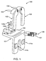
- distal femoral alignment assembly 100 is shown in an exploded view.
- distal femoral alignment assembly 100 can be used for either the left or right knee, i.e., one side of the distal femoral alignment assembly may be the medial side while the other is the lateral side and vice versa.
- Distal femoral alignment assembly 100 comprises a main body 101, an adjustable medial femoral portion coupled to the main body, and an adjustable lateral femoral portion coupled to the main body.
- the main body or stationary portion of the distal femoral alignment assembly is generally stationary with respect to the adjustable medial and lateral femoral portions.
- the adjustable medial and lateral femoral portions are adjusted with respect to the main body.
- Adjustable medial and lateral femoral portions respectively comprise medial and lateral paddles 102, 103.
- the medial and lateral paddles each comprise anti-rotation shafts 104, 105 which fit into slots 106 of the main body.
- Medial and lateral distraction screws 107, 108 respectively couple the medial and lateral paddles 102, 103 with the main body 101.
- Distraction screw capture pegs 109, 110 fix the axial position of the distraction screws 107, 108 relative to the main body 101 such that rotation of the medial and lateral distraction screws only adjusts the positions of the adjustable medial and lateral femoral portions with respect to the main body 101.
- the main body comprises mounts for attachment of a force sensor 111.
- the main body 101 of the distal femoral adjustment assembly 100 further defines cutting guide locating apertures on its medial 113a-c and lateral 112a-c sides. These apertures are cutting guide locating means, e.g., by facilitating the placement of placement pins from which provide points of reference for the placement of a cutting guide.
- the main body further defines slots or verification attachment slots or apertures 114a, 114b for attaching a knee alignment verification means as described below.
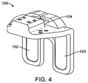
- Figures 2 and 4 show the distal femoral adjustment assembly 100 unadjusted.
- Figures 3 and 5 show the distal femoral adjustment assembly 100 adjusted, i.e., the position of one paddle of the distal femoral adjustment assembly has been moved relative to the other.
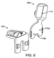
- Figures 6 and 7 show a perspective view of a knee alignment system 99a.
- the system comprises the distal femoral adjustment assembly 100 as described above.
- the system further comprises a electronic force-sensing means or force sensor 115 coupleable with the distal femoral adjustment assembly 100.
- the force sensor 115 comprises a handheld tool but may alternatively be a smaller device coupleable with the main body of the distal femoral adjustment assembly 100.
- the force sensor 115 senses the force between the medial portion of the distal femur and the medial portion of the tibial plateau as well as the force between the lateral portion of the distal femur and the lateral portion of the tibial plateau, for example, by comprising first and second force sensing portions 116a, 116b, the first force sensing portion 116a being a lateral force sensing portion while the second 116b is a medial force sensing portion and vice versa.
- the distal femur and tibial plateau are not shown in Figs. 6-7 .
- the force sensor 115 may be similar to those described U.S. Patent Applications Nos.
- Figure 8 shows a visual display 117 coupleable with the force sensor 115.
- the visual display displays data representative of the force sensed by the force sensor and may be similar to those described in U.S. Patent Applications Nos. 10/973,936 , now U.S. Patent No. 7,578,821 , entitled “Dynamic Knee Balancer with Pressure Sensing” (Attorney Docket No. 021976- 000210US); 61/090,535 entitled “Sensing Force During Partial and Total Knee Replacement Surgery” (Attorney Docket No. 021976-000800US); and 61/107,973 entitled “Dynamic Knee Balancing for Revision Procedures" (Attorney Docket No. 021976-000700US).
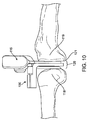
- Figures 9-23 show a method of using an exemplary knee alignment system during knee replacement surgery.
- the force sensor 115 is coupled to the distal femoral alignment assembly 100.
- the distal femoral alignment assembly 100 and the coupled force sensor 115 are placed in the gap 120 between the distal femur 118 and the tibial plateau 121 of the knee.
- the force sensor 115 senses the forces between the lateral and medial portions of the distal femur and the tibial plateau.
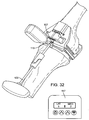
- the visual display 117 shows the sensed forces (as an example, the display shows the forces unbalanced).
- An adjustment wrench 122 is coupled to a rotatable distraction screw 107 of the distal femoral alignment assembly 100.
- the knee may be misaligned, i.e., the femoral axis and the tibial axis are not aligned with each other as in a normal knee.
- the knee may be misaligned, i.e., the femoral axis and the tibial axis are not aligned with each other as in a normal knee.
- the bottom surface of the distal femoral alignment assembly is 80° relative to the mechanical axis 123 of the femur 118.
- At least one of the rotatable screws 107, 108 is rotated with the adjustment wrench 122 to adjust the relative position of the adjustable medial and/or femoral portions and to correct the alignment of the knee.
- the adjustment wrench 122 to adjust the relative position of the adjustable medial and/or femoral portions and to correct the alignment of the knee.
- correct alignment of the knee can be achieved (as shown in the visual display).
- the distal femoral alignment assembly 100 has been adjusted so that the bottom surface of the distal femoral alignment assembly is 85° relative to the mechanical axis 123 of the femur 118.
- the system will typically further comprise a knee alignment verification means to verify the alignment of the knee by verifying the angle formed by the mechanical axes of the femur and tibia.
- the knee alignment verification means may be a laser knee alignment verification member 124 coupleable to the main body of the distal femoral alignment member 100.
- the laser knee alignment verification member 124 emits a femoral laser beam 125a to be aligned along the mechanical axis 123a of the femur and a tibial laser beam 125b to be aligned along the mechanical axis 123b of the tibia.
- the knee alignment verification means may be a mechanical knee alignment verification assembly 126.
- the mechanical knee alignment verification assembly 126 comprises a mechanical knee alignment verification hub 127, a femoral alignment rod 128 coupleable with the hub 127, and a tibial alignment rod 129 coupleable with the hub 127.
- the coupled femoral alignment rod 127 can be aligned along the mechanical axis 123a of the femur 118.
- the coupled tibial alignment rod 129 can be aligned along the mechanical axis 123b of the tibia 119.
- the angle of the femoral alignment rod 128 and the tibial alignment rod 129 relative to each other can be used by the surgeon to verify proper alignment of the knee.
- the system may further comprise a plurality of locating pins 130a, 130b.
- at least one locating pin 130a and/or 130b
- at least one locating pin may be placed on the medial side of the distal femur 118 and at least one locating pin may be placed on the lateral side of the distal femur as guided by the apertures of the distal femoral alignment assembly.
- the distal femoral alignment assembly 100 may be disengaged from the distal femur.
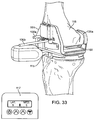
- the system may further comprise a distal femoral cutting guide 131 which can be coupled to the distal femur 118 and positioned based on the position of the locating pins 130a, 130b. Cuts are made on the distal femur 118, for example, with a surgical saw blades 132. Typically, these cuts will form the basis for positioning of the femoral portion of an artificial knee. Exemplary surgical saw blades which may be used to make these cuts on the distal femur are described co-assigned U.S. Patents Nos. 6,022,353 ; 6,503,253; and 6,723,101 .
- an alternative distal femoral alignment system 99b including cutting guide 131 for making a provisional cut on the distal femur in order to mount the distal femoral alignment assembly 100 flush against the provisionally cut distal femur.
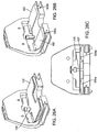
- angular graduation marks 133 are provided. The graduation marks correspond to movement created by adjusting either the medial or lateral distraction paddles 102, 103 as shown in Figure 26B .
- a right distal femur is shown in Figs. 27-28 and 34-35 and a right knee joint with femur and tibia is shown in Figures 29-33 .
- Convex shaped pivot fulcrums 500a, 500b are provided on the surfaces of the distraction paddles 102, 103 which directly contact the provisionally cut distal femur when the distal femoral alignment assembly 100 is mounted against the distal femur 118.
- the curved surface of the distraction paddles 102, 103 creates fixed distance fulcrum points to determine how much angle is being adjusted.
- Figures 26A and 26C show another embodiment of the distal femoral alignment assembly 100 of the alternative distal femoral alignment system 99b shown in Figure 24 , which includes bone interface plate 137.
- This plate 137 provides protection from convex shaped distraction paddles 102 and 103 from indenting the softer cancellous bone exposed as a result of a provisional cut being made on the distal femur 118 (not shown in Fig. 26).
- Figure 26C shows the bone interface plate 137 sitting on top of convex shaped distraction paddles 102 and 103 in their unadjusted position.
- Figures 27-35 a method of using an exemplary knee alignment system used during knee replacement surgery is shown.
- a bone cut has already been made on the proximal tibia 119 prior to the methods described in Figures 27-35 .
- Figure 27 shows provisional distal femoral cutting guide 131 moveably attached to the provisionally cut distal femur 118 via two pins 130a and 130b.
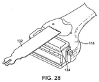
- Figure 28 shows provisional femoral cutting guide 131 and pins 130a and 130b now having been removed and femoral anterior-posterior cutting guide 134 is now removably attached to distal femur 1 18.
- Saw blade 132 is shown and the anterior and posterior bone cuts are performed on distal femur 118.
- Figure 29 shows now the "extension gap" with the proximal tibial cut having been made and a provisional distal femoral cut having been made.
- the posterior femoral cut has also been made but hidden from view in Figure 29 .
- the anterior cut has also been made on distal femur 118.
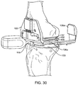
- distal femoral alignment assembly 100 and other components of the distal femoral alignment system 99b are shown between the proximal tibia 119 and the distal femur 118, with the leg in full extension.
- Thickness adapter 133 is shown moveably coupled to force sensor 115, and force sensor 115 is moveable coupled to distal femoral assembly 100.
- Adjustable posterior member 135a is shown adjacent to a longitudinal slot 400 open on the posterior side of distal femoral assembly 100, with the slot closed on the anterior side of the distal femoral assembly 100.
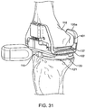
- Figure 31 shows adjustable posterior member 135a having now been moveably coupled within the longitudinal slot 400 along the medial side of distal femoral assembly 100.
- Moveable coupling means 136a, 136b can include magnets or other common coupling means such as screws or spring clips.
- Longitudinal slots are also provided on the opposite side of the distal femoral assembly 100. Longitudinal slots along the sides of distal femoral assembly 100 are of adequate length to allow for anterior-posterior adjustment of adjustable posterior member to abut the previously made posterior cut 401 of the distal femur 118.
- the adjustable posterior members further balance extension filling the posterior space with a condylar thickness similar to the posterior condylar thickness of the femoral component to be implanted thus taking into account soft-tissue tendancies, or bias.
- Figure 32 shows components and assemblies of the distal femoral alignment system 99b now completely in place between the proximal tibia and the distal femur and force readings coupled from force sensor 115 are being displayed on display 117, It is understood that display 117 may be integral to force sensor 115. The display 117 can also be separable from the sensor. The display 117 is showing force readings of 5 and 2 lateral and medial respectively, indicating lower force between the medial side of the distal femur and the medial side of the proximal tibia, in this example. Adjustment wrench 122 is shown in line with the medial distraction screw 107.
- Figure 33 shows the medial distraction paddle 102 having now been adjusted to a point wherein the forces being measured by sensor 115 and displayed by display 117 read 5 on both the lateral and the medial side.
- Pin 130a is shown being driven through a lateral side cutting guide locating aperture and pin 130b has yet to be driven through the medial side cutting guide locating aperture.
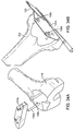
- Figure 34A shows both pins having now been driven through cutting guide locating apertures of distal femoral assembly 100, and distal femoral assembly 100 now having been removed from the distal femur 118.
- Cutting guide 131b is positioned over pins 130a and 130b.
- Figure 34B shows cutting guide 131 b now positioned over pins 130a and 130b and saw blade 132 will be used to make the final distal femoral cut at an angle "A" which is the plane of balanced resection as determined by the force sensor.
- Figure 35 shows femoral anterior-posterior cutting guide 134 now removably coupled to distal femur 118 and saw blade 132 is shown making a final cut on the anterior distal femur. Anterior and posterior chamfer cuts will also be made on the distal femur 118 at this point.
Landscapes
- Health & Medical Sciences (AREA)
- Surgery (AREA)
- Life Sciences & Earth Sciences (AREA)
- Medical Informatics (AREA)
- Molecular Biology (AREA)
- Veterinary Medicine (AREA)
- Nuclear Medicine, Radiotherapy & Molecular Imaging (AREA)
- Public Health (AREA)
- General Health & Medical Sciences (AREA)
- Engineering & Computer Science (AREA)
- Biomedical Technology (AREA)
- Heart & Thoracic Surgery (AREA)
- Animal Behavior & Ethology (AREA)
- Dentistry (AREA)
- Orthopedic Medicine & Surgery (AREA)
- Physical Education & Sports Medicine (AREA)
- Transplantation (AREA)
- Oral & Maxillofacial Surgery (AREA)
- Surgical Instruments (AREA)
Description
- The present application is a non-provisional of, and claims the benefit of priority under 35 U.S.C. $ 119(e),
U.S. Provisional Application No. 61/109,770 - The present invention relates generally to medical surgical systems. More specifically, the invention relates to systems for facilitating knee surgery procedures, in particular, knee replacement procedures.
- The knee is generally defined as the point of articulation of the femur with the tibia. Structures that make up the knee include the distal femur, the proximal tibia, the patella, and the soft tissues within and surrounding the knee joint, the soft tissues including the ligaments of the knee. The knee is generally divided into three compartments: medial (the inside part of the knee), lateral (the outside part of the knee), and patello-femoral (the joint between the kneecap and the femur). The medial compartment comprises the medial joint surfaces of the femur, tibia, and the meniscus wedged therebetween. The lateral compartment comprises the lateral joint surfaces of the femur, tibia, and the meniscus wedged therebetween. The patellofemoral compartment comprises the joint between the undersurface of the kneecap or patella and the femur. Four ligaments are especially important in the stability, alignment and functioning of the knee-the anterior cruciate ligament, the posterior cruciate ligament, the medial collateral ligament, and the lateral collateral ligament. In an arthritic knee, protective cartilage at the point of articulation of the femur with the tibia is often worn away, allowing the femur to directly contact the tibia. This bone-on-bone contact can cause significant pain, discomfort, and disability for a patient and will often necessitate knee replacement or knee arthroplasty.
- Knee arthroplasty involves replacing the diseased and painful joint surface of the knee with metal and plastic components shaped to allow natural motion of the knee. Knee replacement may be total or partial. Total knee replacement surgery, also referred to as total knee arthroplasty ("TKA"), involves a total replacement of the distal end of the femur, the proximal end of the tibia, and often the inner surface of the patella with prosthetic parts. Cuts are made on the distal end of the femur and the proximal end of the tibia. Prosthetic parts are then attached. The prosthetic parts create a stable knee joint that moves through a wide range of motion. The replacement of knee structures with prosthetic parts allows the knee to avoid bone-on-bone contact and provides smooth, well-aligned surfaces for joint movement.
- In knee replacement surgeries, it is often vital to restore the mechanical alignment of the knee, i.e., the proper alignment of the mechanical axes of the femur and tibia with each other. Many methods and devices currently are used to restore the mechanical alignment of the leg. These methods and devices are typically used during Total Knee Replacement surgery and include alignment rods, e.g., intramedullary and extramedullary rods, surgical navigation systems, and CT and or MRI based "bone morphing" or 'shape-fitting" technologies. Generally, empirical anatomical landmarks are used in these methods. These anatomical landmarks are either directly/mechanically observed intra-operatively, or indirectly relied upon, serving as the foundation of a computer generated reference method. Reference geometry and physical or virtual measurements are often used to ultimately align bone-cutting guides or templates which facilitate bone resections (made with a surgical saw blade). These bone resections will typically properly orient a knee prosthesis in the correct location/alignment. Generally, none of these methods directly take the condition or tendencies of the soft-tissue structures, such as the lateral collateral and medial collateral ligaments, about the knee into consideration.
- Historically, surgeons performing total knee replacement surgery in the late 1970s and early 1980s, would typically first resect the proximal tibia, creating a flat surface perpendicular to the shaft of the tibia. The leg was then brought to extension. Spacer blocks were shoved between the resected tibia and the uncut distal femur. The spacer blocks were selected from various thicknesses in order to distract the knee joint space to the extent the ligaments about the knee were somewhat taut. Once the knee joint was distracted to that taut condition, a distal femoral cutting guide was positioned in a way to yield a distal femoral bone cut parallel to the tibial cut. It was believed then, a distal femoral bone cut using this method of distracting the joint space between the tibia and femur, would yield proper alignment of the mechanical axis of the leg. This method would often prove successful as practiced by a skilled surgeon and in the case of "passive deformities" of the knee. However, the distraction method would typically not have any accurate means of determining ligament forces between the medial side of the knee and/or the lateral side of the knee. As such, proper alignment would often not be restored. Additionally, the method of first making a proximal tibial bone resection and then making a distal femoral bone resection parallel to the tibial bone resection did not restore proper alignment of the leg in the case of "fixed deformities" of the knee. The case of "fixed deformities" of the knee would otherwise require ligament releases to restore proper alignment of the knee. Accordingly, many early knee replacement surgeons determined the tibial bone resection and the distal femoral bone resections should be made independent of each other.
- As technology has advanced, including the introduction of CT scanners and MRI technology, the thought of computerized bone morphing has gained popularity as a means to accurately place cutting guides. The cutting guides in turn would be used in efforts to place prosthetic knee implants in a position in which the knee is properly aligned. Early studies have not found these bone morphing technologies always accurate, reporting proper alignment of the leg was not restored. However, a proper patient selection, e.g., patients with mild, passive deformities of the knee, might be viable candidates for bone morphing technology, assuming those patients/deformities could be properly corrected by simple anatomical referencing, as determined by a CT or MRI scan.
- However, bone morphing technology is often costly, requiring a CT or MRI scan to determine any given patient's anatomy. Electronic images from such scans must be "filtered" by a computer technician. The "filtered" scan data must be electronically conveyed to some type of fabrication machine, such as a CNC Machining Center or a Rapid Prototype Machine. Ultimately, "shape-matching" and "patient specific" cutting guides must be produced and delivered into surgery.
- As such, there is a clear need for systems, devices, and methods of knee surgery that can help surgeons quickly, accurately, and cost-effectively position the distal femoral cutting guide, thus restoring proper alignment and soft-tissue balance of the leg during total knee replacement surgery.
- Non-patent literature which may be of interest may include: Murray, David G., "Variable Axis(TM) Total Knee Surgical Technique," Howmedica Surgical Techniques, Howmedica Inc. 1977; Mihalko, WH et al., "Comparison of Ligament-Balancing Techniques During Total Knee Arthroplasty," JnI. Bone & Jt. Surg., Vol. 85-A ; Eckhoff, D G et al., "Three-Dimensional Morphology and Kinematics of the Distal Part of the Femur Viewed in Virtual Reality, JnI. Bone & Jt. Surg., Vol. 85-A ; and Ries, M D, et al., "Soft-Tissue Balance in Revision Total Knee Arthroplasty," JnI. Bone & Jt. Surg., Vol. 85-. Patents of interest may include
U.S. Patents Nos. 4,501,266 ;4,646,729 ;4,703,751 ;4,841,975 ;5,116,338 ;5,417,694 ;5,540,696 ;5,597,379 ;5,720,752 ;5,733,292 ;5,800,438 ;5,860,980 ;5,911,723 ;6,022,377 and6,758,850 . Patents applications of interest may include co-assignedU.S. Patent Applications Nos. 10/773,608 , nowU.S. Patent No. 7,442,196 , entitled "Dynamic Knee Balancer" (Attorney Docket No. 021976- 000200US);10/973,936 U.S. Patent No. 7,578,821 entitled "Dynamic Knee Balancer with Pressure Sensing" (Attorney Docket No. 021976-000210US);11/149,944 U.S. Patent Publication Application No. 2005/0267485 A1 entitled "Dynamic Knee Balancer with Opposing Adjustment Mechanism" (Attorney Docket No. 021976-000220US);61/090,535 61/107,973 -
US 2007/0244488 describes a tensor for use with a surgical navigation system. The tensor comprises a first bone engaging member engageable with a first bone and a second bone engaging member engageable with a second bone. A force-applying mechanism is confirmed to forcibly move the first and second bone engaging members relative to one another and a sensor detects the value of the force applied by the force-applying mechanism. A transmitter communicates a parameter associated with the tensor to the surgical navigation system. -
US 2005/0267485 describes a device for performing a surgical procedure on a knee comprising a stationary femoral member attachable to the distal femur, an adjustable femoral member moveable coupled with the stationary member to address tension in at least one ligament of or adjacent the knee and an adjustment mechanism coupled to the assembly. -
US 5,213,112 describes a tension meter for orthopaedic surgery for measuring the degree of tension between bones. - The present invention is set out in the appended claims. Described herein are devices, systems, and methods for facilitating a surgery performed on a knee, particularly by facilitating the aligning of the knee during a total knee replacement surgery. A femoral assembly is engaged with a distal femur and placed in the gap between the distal femur and proximal tibia. The femoral assembly comprises a stationary portion, an adjustable medial portion, and an adjustable lateral femoral portion. The positions of the medial and lateral femoral portions relative to the stationary portion can be separately adjusted to adjust the varus-valgus alignment of the knee, e.g., the angle between the femur and tibia, as well as the tension in the soft tissues adjacent the knee. Additionally, the femoral assembly comprises adjustable posterior members that fill the posterior capsule of the knee with a thickness similar to the prosthetic femoral implant. Typically, a force sensor will be provided to sense the forces in the medial portion of the knee and the lateral portion of the knee, and the medial and lateral femoral portions will be adjusted so that the sensed forces are balanced. A visual display may be provided to show the surgeon the sensed forces. In addition, a thickness adapter may be provided to removable attach to the force sensor to fill the space between the femur and tibia to the point force readings are obtained. The alignment of the knee can be visually verified using a knee alignment verification member coupled to the femoral assembly, and further verified by angular graduation markings placed upon the femoral stationary portion. The knee alignment verification member may emit laser beams along the mechanical axes of the femur and tibia. Or, alignment rods which align along the mechanical axes of the femur and tibia may be coupled to the knee alignment verification member. The alignment of the knee can be verified using with the laser beams and/or the alignment rods. When the knee is properly aligned, placement pins may be positioned in the distal femur guided by the femoral assembly. The femoral assembly can then be removed and a cutting guide can be positioned on the distal femur based on the position of the placement pins. A cut parallel to a previously made cut on the tibia can then be made on the distal femur. A prosthetic knee placed on these cuts will maintain the proper alignment of the knee.
- Described herein is a system for aligning the knee during a surgical procedure on the knee. The system comprises a femoral assembly that is removably engaged with a distal femur. The femoral assembly includes a stationary femoral portion, an adjustable medial femoral portion (which is coupled to the stationary femoral portion), and an adjustable lateral femoral portion (which is coupled to the stationary femoral portion. A knee alignment verification member is coupled with the stationary femoral portion of the femoral assembly and provides visual confirmation of a femoral and tibial mechanical axes of the knee. A force sensor is coupled with the stationary femoral portion of the femoral assembly. The force sensor comprises a medial portion for sensing a first force in a medial portion of the knee and a lateral portion for sensing a second force in a lateral portion of the knee.
- In one embodiment, the knee alignment verification member means includes a laser knee alignment verification member is coupled to the stationary femoral portion. The laser knee alignment provides a first laser beam oriented along the femoral axis of the knee and a second laser beam oriented along the tibial axis of the knee.
- In some embodiments, the knee alignment verification member includes a mechanical knee alignment verification assembly. The mechanical knee alignment verification assembly includes a knee alignment hub. A first rod is coupled with the knee alignment hub to be oriented along the femoral axis of the knee and a second rod is coupled with the knee alignment hub to be oriented along the tibial axis of the knee.
- In an embodiment, the adjustable medial portion includes a medial paddle and the adjustable femoral portion includes a lateral paddle.
- In still other embodiments, the position of the adjustable medial femoral portion relative to the stationary femoral portion is adjustable. The position of the adjustable lateral femoral portion relative to the stationary femoral portion is adjustable.
- In other embodiments, the adjustable medial femoral portion and the adjustable lateral femoral portion are separately adjustable.
- In some embodiments, a medial rotatable screw couples the adjustable medial femoral portion with the stationary femoral portion. A lateral rotatable screw couples the adjustable lateral femoral portion with the stationary femoral portion.
- In some embodiments, rotating the medial rotatable screw adjusts the position of the adjustable medial femoral portion relative to the stationary femoral portion. Rotating the lateral rotatable screw adjusts the position of the adjustable lateral femoral portion relative to the stationary femoral portion.
- In some embodiments, the force sensor comprises a force sensing element selected from the group consisting of piezoelectric sensors, force sensing resistors, force sensing capacitors, strain gages, load cells, and pressure sensors.
- In still other embodiments, a processor is coupled with the force sensor for processing sensed force data into usable data and for providing the data to a user. A visual display is coupled with the processor and adapted to display the usable data.
- In some embodiments, the visual display displays usable data representing a first force sensed in the medial portion of the knee and a second force sensed in the lateral portion of the knee.
- In some embodiments, the system for aligning a knee during knee surgery includes a plurality of locating pins. The stationary femoral portion defines at least one medial aperture for positioning at least one locating pin on the distal femur and at least one lateral aperture for positioning at least a second locating pin on the distal femur.
- In some embodiments, a cutting guide is removably engaged with the distal femur. The cutting guide is positioned relative to the distal femur based on the position of at least one first locating pin and the at least a second locating pin.
- In some embodiments, the force sensor is removably coupled to a thickness adapter. The adapter fills the space between the femur and tibia.
- In some embodiments, the adjustable medial femoral portion and the adjustable lateral femoral portion include a medial fulcrum and lateral fulcrum. The fulcrums are positioned against the provisionally cut distal femur when the distal femoral alignment assembly is mounted against the distal femur. In other embodiments, a bone interface plate is disposed between the fulcrums and the distal femur.
- Described herein is a method for aligning the knee during a surgical procedure on the knee including engaging a femoral assembly with a distal femur. The femoral assembly includes a stationary femoral portion, an adjustable medial femoral portion (coupled to the stationary femoral portion), and an adjustable lateral femoral portion (coupled to the stationary femoral portion). A force sensor is coupled with the stationary femoral portion of the femoral assembly. A first force is sensed in a medial portion of the knee and a second force is sensed in the lateral portion of the knee using the coupled force sensor. The position of the adjustable medial femoral portion can be adjusted separately relative to the stationary femoral portion based on the sensed first and second forces to align a femoral and tibial mechanical axes of the knee. Te alignment of the femoral and tibial mechanical axes of the knee are visually confirmed using a knee alignment verification assembly coupled with the stationary femoral portion of the femoral assembly.
- In one example, a method for aligning the knee during a surgical procedure on the knee comprises coupling a mechanical knee alignment verification assembly with the stationary femoral member of the femoral assembly. A first alignment rod of the mechanical knee alignment verification assembly is aligned along the femoral axis of the knee and a second alignment rod of the mechanical knee alignment verification assembly is aligned along the tibial axis of the knee. The femoral and tibial mechanical axes of the knee is visually confirmed by the alignment of the first alignment rod and the second alignment rod relative to each other.
- In another example, a laser knee alignment verification member is coupled with the stationary femoral member of the femoral assembly, A first laser beam from the laser knee alignment verification member is aligned along the femoral mechanical axis of the knee and a second laser beam from the laser knee alignment verification member is aligned along the tibial mechanical axis of the knee along the tibial axis of the knee, The alignment of the femoral and tibial mechanical axes of the knee is visually confirmed by the alignment of the first laser beam and the alignment of the second laser beam relative to each other.
- In some examples, the positions of the adjustable medial femoral portion relative to the stationary femoral portion and of the adjustable lateral femoral portion relative to the stationary femoral portion are adjusted based on the sensed first force and the sensed second force so that the first and second forces are balanced.
- In some examples, the first force in a medial portion of the knee is sensed and a second force in a lateral portion of the knee is sensed using the coupled force sensor. This includes transmitting a voltage to a sensor element of a thin force sensing portion of the force sensor and measuring the voltage after it has passed through the sensor element. The percentage of the voltage that passed through the sensor element is determined relative to the voltage transmitted to the sensor element. The measured force is derived from the percentage.
- In yet another example, the sensed first force and the sensed second force visually displayed by a display coupled to the force sensor.
- In some examples, separately adjusting the position of the adjustable medial femoral portion relative to the stationary femoral portion and the position of the adjustable lateral femoral portion relative to the stationary femoral portion comprises rotating at least one of a lateral rotatable screw coupling the adjustable lateral femoral portion to the stationary femoral portion and a medial rotatable screw coupling the adjustable medial femoral portion to the stationary femoral portion.
- In some examples, the stationary femoral portion defines at least one medial aperture and at least one lateral aperture. The method further includes positioning at least one locating pin on the distal femur based on at least one medial aperture and positioning at least a second locating pin on the distal femur based on the at least one lateral aperture.
- In an examples, the femoral assembly is disengaged with the distal femur and engages a distal femoral cutting guide with the distal femur. The distal femoral cutting guide is positioned relative to the distal femur based on the position of at least one first and at least one second locating pins.
- In some examples, cuts are made on the distal femur based on the position of the distal femoral cutting guide.
- Described herein is a method for aligning a leg during knee surgery. The leg has a femur and a tibia. The femur has a mechanical axis, a distal end and a proximal end. The tibia has a mechanical axis, a distal end and a proximal end. The method of aligning the leg includes engaging a femoral assembly with the provisionally cut distal end of the femur. The femoral assembly includes a stationary femoral portion, an adjustable medial femoral portion that has a medial pivot fulcrum coupled to the stationary femoral portion, and an adjustable lateral femoral portion that has a lateral pivot fulcrum coupled to the stationary femoral portion. A force sensor is coupled with the stationary femoral portion of the femoral assembly. A medial posterior member is reversibly coupled to the medial side of the stationary femoral portion. A lateral posterior member is reversibly coupled to the lateral side of the stationary femoral portion. The medial member abuts the medial posterior femur and the lateral member abuts the lateral posterior femur. A first force is sensed in a medial portion of the knee and a second force is sensed in the lateral portion of the knee using the force sensor. The position of the adjustable medial femoral portion is adjusted relative to the stationary femoral portion and the position of the adjustable lateral femoral portion is (separately) adjusted relative to the stationary femoral portion based on the sensed first and second forces to align the femoral and tibial mechanical axes of the knee. The alignment of the femoral and tibial mechanical axes of the knee is visually confirmed using a knee alignment verification assembly which is coupled with the stationary femoral portion of the femoral assembly.
- In one example, the medial member abuts the medial posterior femur and the lateral member abuts the lateral posterior femur when the leg is fully extended.
- In some examples, the medial and lateral fulcrums determine fixed distance points to adjust an angle.
- In some examples, a bone interface plate is disposed between the adjustable medial and lateral femoral portions and the distal femur.
-
-
Figure 1 shows an exploded view of a distal femoral alignment component assembly. -
Figure 2 shows a top view of the unadjusted distal femoral alignment assembly ofFigure 1 . -
Figure 3 shows a top view of the adjusted distal femoral alignment assembly ofFigure 1 . -
Figure 4 shows a perspective view of the unadjusted distal femoral alignment assembly ofFigure 1 . -
Figure 5 shows a perspective view of the adjusted distal femoral alignment assembly ofFigure 1 . -
Figures 6 and7 shows perspective views of a knee alignment system. -
Figure 8 shows a visual display of a knee alignment system. -
Figures 9-10 show a side view of a knee alignment system, including the distal femoral alignment component and the force sensor coupled together, being placed in the gap. -
Figures 11-12 show a perspective view of a knee alignment system, including the distal femoral alignment component and the force sensor coupled together, being placed in the gap. -
Figures 13-23 show a method of aligning a knee during surgery. -
Figure 24 A-B shows exploded views of a knee alignment system. -
Figure 25 shows a top view of the unadjusted distal femoral alignment assembly. -
Figures 26A and 26C show perspective posterior views of the unadjusted distal femoral alignment assembly shown inFigure 25 . -
Figure 26B shows a posterior perspective of the unadjusted distal femoral alignment assemblies shown inFigures 26A and 26C with the bone interface plate removed. -
Figures 27-35 show an alternative method of aligning a knee surgery. -
Figure 36 is a flow chart schematically illustrating a method for aligning and balancing a knee during knee surgery. - Described herein are systems, devices, and methods for facilitating the alignment and balancing of the knee during knee replacement surgery and verifying such balance and alignment. Once the knee is properly aligned, a cut parallel to a previously made cut on the tibia can be made on the distal femur. A prosthetic knee placed on these cuts will maintain the proper alignment of the knee.
- Referring now to
Figure 1 , a distal femoral alignment assembly orcomponent 100 is shown in an exploded view. As shown inFigure 1 , distalfemoral alignment assembly 100 can be used for either the left or right knee, i.e., one side of the distal femoral alignment assembly may be the medial side while the other is the lateral side and vice versa. Distalfemoral alignment assembly 100 comprises amain body 101, an adjustable medial femoral portion coupled to the main body, and an adjustable lateral femoral portion coupled to the main body. When the distalfemoral alignment assembly 100 is coupled to a distal femur, the main body or stationary portion of the distal femoral alignment assembly is generally stationary with respect to the adjustable medial and lateral femoral portions. The adjustable medial and lateral femoral portions are adjusted with respect to the main body.
Adjustable medial and lateral femoral portions respectively comprise medial andlateral paddles anti-rotation shafts slots 106 of the main body. Medial and lateral distraction screws 107, 108 respectively couple the medial andlateral paddles main body 101. Distraction screw capture pegs 109, 110 fix the axial position of the distraction screws 107, 108 relative to themain body 101 such that rotation of the medial and lateral distraction screws only adjusts the positions of the adjustable medial and lateral femoral portions with respect to themain body 101. The main body comprises mounts for attachment of a force sensor 111. - Referring now to
Figure 2 , themain body 101 of the distalfemoral adjustment assembly 100 further defines cutting guide locating apertures on its medial 113a-c and lateral 112a-c sides. These apertures are cutting guide locating means, e.g., by facilitating the placement of placement pins from which provide points of reference for the placement of a cutting guide. The main body further defines slots or verification attachment slots orapertures -
Figures 2 and4 show the distalfemoral adjustment assembly 100 unadjusted.Figures 3 and5 show the distalfemoral adjustment assembly 100 adjusted, i.e., the position of one paddle of the distal femoral adjustment assembly has been moved relative to the other. -
Figures 6 and7 show a perspective view of aknee alignment system 99a. The system comprises the distalfemoral adjustment assembly 100 as described above. The system further comprises a electronic force-sensing means orforce sensor 115 coupleable with the distalfemoral adjustment assembly 100. As shown, theforce sensor 115 comprises a handheld tool but may alternatively be a smaller device coupleable with the main body of the distalfemoral adjustment assembly 100. Theforce sensor 115 senses the force between the medial portion of the distal femur and the medial portion of the tibial plateau as well as the force between the lateral portion of the distal femur and the lateral portion of the tibial plateau, for example, by comprising first and secondforce sensing portions force sensing portion 116a being a lateral force sensing portion while the second 116b is a medial force sensing portion and vice versa. The distal femur and tibial plateau are not shown inFigs. 6-7 . Theforce sensor 115 may be similar to those describedU.S. Patent Applications Nos. 61/090,535
(Attorney Docket No. 021976-000800US) and 61/107,973 entitled "Dynamic Knee Balancing for Revision Procedures" (Attorney Docket No. 021976-000700US). -
Figure 8 shows avisual display 117 coupleable with theforce sensor 115. The visual display displays data representative of the force sensed by the force sensor and may be similar to those described inU.S. Patent Applications Nos. 10/973,936 , nowU.S. Patent No. 7,578,821 , entitled "Dynamic Knee Balancer with Pressure Sensing" (Attorney Docket No. 021976- 000210US);61/090,535 61/107,973 -
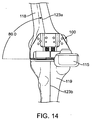
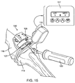
Figures 9-23 show a method of using an exemplary knee alignment system during knee replacement surgery. As shown inFigures 9 and11 , theforce sensor 115 is coupled to the distalfemoral alignment assembly 100. As shown inFigures 10 and12 , the distalfemoral alignment assembly 100 and the coupledforce sensor 115 are placed in thegap 120 between thedistal femur 118 and thetibial plateau 121 of the knee. As shown inFigure 13 , theforce sensor 115 senses the forces between the lateral and medial portions of the distal femur and the tibial plateau. Thevisual display 117 shows the sensed forces (as an example, the display shows the forces unbalanced). Anadjustment wrench 122 is coupled to arotatable distraction screw 107 of the distalfemoral alignment assembly 100. As shown inFigure 14 , when the unadjusted distalfemoral alignment assembly 100 and the coupledforce sensor 115 are first placed in thegap 120 between thedistal femur 118 and thetibial plateau 121, the knee may be misaligned, i.e., the femoral axis and the tibial axis are not aligned with each other as in a normal knee. As shown inFigure 14 , when the unadjusted distalfemoral alignment assembly 100 and the coupledforce sensor 115 are first placed in thegap 120 between thedistal femur 118 and thetibial plateau 121, the knee may be misaligned, i.e., the femoral axis and the tibial axis are not aligned with each other as in a normal knee. As shown inFigure 14 , the bottom surface of the distal femoral alignment assembly is 80° relative to the mechanical axis 123 of thefemur 118. As shown inFigure 15 , at least one of therotatable screws adjustment wrench 122 to adjust the relative position of the adjustable medial and/or femoral portions and to correct the alignment of the knee. Generally, by balancing the sensed forces in the medial and lateral portions of the knee, correct alignment of the knee can be achieved (as shown in the visual display). For example, as shown inFigure 16 , the distalfemoral alignment assembly 100 has been adjusted so that the bottom surface of the distal femoral alignment assembly is 85° relative to the mechanical axis 123 of thefemur 118. - The system will typically further comprise a knee alignment verification means to verify the alignment of the knee by verifying the angle formed by the mechanical axes of the femur and tibia. As shown in
Figures 17 and18 , the knee alignment verification means may be a laser kneealignment verification member 124 coupleable to the main body of the distalfemoral alignment member 100. As shown inFigure 18 , the laser kneealignment verification member 124 emits afemoral laser beam 125a to be aligned along themechanical axis 123a of the femur and a tibial laser beam 125b to be aligned along themechanical axis 123b of the tibia. The angle of the femoral laser beam and the tibial laser beam relative to each other can be used by the surgeon to verify the proper anatomical alignment of the knee, i.e., the angle between themechanical axes Figures 19 and20 , the knee alignment verification means may be a mechanical kneealignment verification assembly 126. The mechanical kneealignment verification assembly 126 comprises a mechanical kneealignment verification hub 127, afemoral alignment rod 128 coupleable with thehub 127, and atibial alignment rod 129 coupleable with thehub 127. The coupledfemoral alignment rod 127 can be aligned along themechanical axis 123a of thefemur 118. The coupledtibial alignment rod 129 can be aligned along themechanical axis 123b of thetibia 119. The angle of thefemoral alignment rod 128 and thetibial alignment rod 129 relative to each other can be used by the surgeon to verify proper alignment of the knee. - As shown in
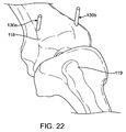
Figure 21 , the system may further comprise a plurality of locatingpins distal femur 118 and at least one locating pin may be placed on the lateral side of the distal femur as guided by the apertures of the distal femoral alignment assembly. As shown inFigure 22 , once the locatingpins distal femur 118, the distalfemoral alignment assembly 100 may be disengaged from the distal femur. - As shown in
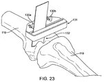
Figure 23 , the system may further comprise a distalfemoral cutting guide 131 which can be coupled to thedistal femur 118 and positioned based on the position of the locatingpins distal femur 118, for example, with asurgical saw blades 132. Typically, these cuts will form the basis for positioning of the femoral portion of an artificial knee. Exemplary surgical saw blades which may be used to make these cuts on the distal femur are described co-assignedU.S. Patents Nos. 6,022,353 ;6,503,253; and 6,723,101 - Referring now to
Figures 24A-B , an alternative distalfemoral alignment system 99b is shown including cuttingguide 131 for making a provisional cut on the distal femur in order to mount the distalfemoral alignment assembly 100 flush against the provisionally cut distal femur. As shown inFigure 25 , angular graduation marks 133 are provided. The graduation marks correspond to movement created by adjusting either the medial or lateral distraction paddles 102, 103 as shown inFigure 26B . For clarity purposes, a right distal femur is shown inFigs. 27-28 and34-35 and a right knee joint with femur and tibia is shown inFigures 29-33 . The medial side of components or assemblies of the distal femoral alignment system shown inFigure 24 are hereby described either medial or lateral based on their position when used on a right knee. Of course, the invention can be used on the left and/or right knees. Convex shapedpivot fulcrums femoral alignment assembly 100 is mounted against thedistal femur 118. The curved surface of the distraction paddles 102, 103 creates fixed distance fulcrum points to determine how much angle is being adjusted.Figures 26A and 26C show another embodiment of the distalfemoral alignment assembly 100 of the alternative distalfemoral alignment system 99b shown inFigure 24 , which includesbone interface plate 137. Thisplate 137 provides protection from convex shaped distraction paddles 102 and 103 from indenting the softer cancellous bone exposed as a result of a provisional cut being made on the distal femur 118 (not shown inFig. 26). Figure 26C shows thebone interface plate 137 sitting on top of convex shaped distraction paddles 102 and 103 in their unadjusted position.Shoulder screw 138 is shown, which slips through a loosely fittedhole 139 inbone interface plate 137 to allow for tilting ofbone interface plate 137 when convex shaped distraction paddles 102 and 103 are adjusted from their unadjusted position to an adjusted position. Spacing between convex shaped adjustment paddles 102 and 103 is maintained in the medial-lateral direction to provide for a known pivot fulcrum between the two convex shaped adjustment paddles, which corresponds toangular graduations 133 shown inFigure 25 . The angular gradations provide an indication of the angle between the femur and tibia - Referring now to
Figures 27-35 , a method of using an exemplary knee alignment system used during knee replacement surgery is shown. For purposes of clarity, a bone cut has already been made on theproximal tibia 119 prior to the methods described inFigures 27-35 .Figure 27 shows provisional distalfemoral cutting guide 131 moveably attached to the provisionally cutdistal femur 118 via twopins Figure 28 shows provisionalfemoral cutting guide 131 andpins posterior cutting guide 134 is now removably attached todistal femur 1 18.Saw blade 132 is shown and the anterior and posterior bone cuts are performed ondistal femur 118.Figure 29 shows now the "extension gap" with the proximal tibial cut having been made and a provisional distal femoral cut having been made. The posterior femoral cut has also been made but hidden from view inFigure 29 . The anterior cut has also been made ondistal femur 118. - Moving now to
Figure 30 , the distalfemoral alignment assembly 100 and other components of the distalfemoral alignment system 99b are shown between theproximal tibia 119 and thedistal femur 118, with the leg in full extension.Thickness adapter 133 is shown moveably coupled to forcesensor 115, andforce sensor 115 is moveable coupled to distalfemoral assembly 100.Adjustable posterior member 135a is shown adjacent to alongitudinal slot 400 open on the posterior side of distalfemoral assembly 100, with the slot closed on the anterior side of the distalfemoral assembly 100.Figure 31 showsadjustable posterior member 135a having now been moveably coupled within thelongitudinal slot 400 along the medial side
of distalfemoral assembly 100. Moveable coupling means 136a, 136b can include magnets or other common coupling means such as screws or spring clips. Longitudinal slots are also provided on the opposite side of the distalfemoral assembly 100. Longitudinal slots along the sides of distalfemoral assembly 100 are of adequate length to allow for anterior-posterior adjustment of adjustable posterior member to abut the previously madeposterior cut 401 of thedistal femur 118. The adjustable posterior members further balance extension filling the posterior space with a condylar thickness similar to the posterior condylar thickness of the femoral component to be implanted thus taking into account soft-tissue tendancies, or bias.Figure 32 shows components and assemblies of the distalfemoral alignment system 99b now completely in place between the proximal tibia and the distal femur and force readings coupled fromforce sensor 115 are being displayed ondisplay 117, It is understood thatdisplay 117 may be integral to forcesensor 115. Thedisplay 117 can also be separable from the sensor. Thedisplay 117 is showing force readings of 5 and 2 lateral and medial respectively, indicating lower force between the medial side of the distal femur and the medial side of the proximal tibia, in this example.Adjustment wrench 122 is shown in line with themedial distraction screw 107.Figure 33 shows themedial distraction paddle 102 having now been adjusted to a point wherein the forces being measured bysensor 115 and displayed bydisplay 117 read 5 on both the lateral and the medial side.Pin 130a is shown being driven through a lateral side cutting guide locating aperture andpin 130b has yet to be driven through the medial side cutting guide locating aperture.Figure 34A shows both pins having now been driven through cutting guide locating apertures of distalfemoral assembly 100, and distalfemoral assembly 100 now having been removed from thedistal femur 118. Cuttingguide 131b is positioned overpins Figure 34B shows cuttingguide 131 b now positioned overpins blade 132 will be used to make the final distal femoral cut at an angle "A" which is the plane of balanced resection as determined by the force sensor.Figure 35 shows femoral anterior-posterior cutting guide 134 now removably coupled todistal femur 118 and sawblade 132 is shown making a final cut on the anterior distal femur. Anterior and posterior chamfer cuts will also be made on thedistal femur 118 at this point. - While the above is a complete description of the preferred embodiments of the invention, various alternatives, modifications, and equivalents may be used. Therefore, the above description should not be taken as limiting in scope of the invention which is defined by the appended claims.
Claims (15)
- A system for aligning the knee during a surgical procedure on the knee, the system comprising:a femoral assembly (100) removably engagable with a distal femur, the femoral assembly including a stationary femoral portion (101), an adjustable medial femoral portion (102) coupled to the stationary femoral portion, and an adjustable lateral femoral portion (103) coupled to the stationary femoral portion;a knee alignment verification member (124; 126) coupleable with the stationary femoral portion (101) of the femoral assembly and providing visual confirmation of a relationship of femoral and tibial mechanical axes of the knee ; anda force sensor (111) coupleable with the stationary femoral portion (101) of the femoral assembly, the force sensor comprising a medial portion for sensing a first force in a medial portion of the knee and a lateral portion for sensing a second force in a lateral portion of the knee, characterised in that the relationship indicated by the knee alignment verification member (124;126) is less than 180 degrees such that the bottom surface of the distal femoral alignment assembly is less than 90 degrees relative to the femoral mechanical axis.
- The system of claim 1, wherein the knee alignment verification member means includes a laser knee alignment verification member (124) coupleable to the stationary femoral portion (101) and providing a first laser beam oriented along the femoral axis of the knee and a second laser beam oriented along the tibial axis of the knee.
- The system of claim 1, wherein the knee alignment verification member includes a mechanical knee alignment verification assembly (126), the mechanical knee alignment verification assembly comprising:a knee alignment hub (127);a first rod (128) coupleable with the knee alignment hub to be oriented along the femoral axis of the knee; anda second rod (129) coupleable with the knee alignment hub to be oriented along the tibial axis of the knee.
- The system of any one of claims 1 to 3, wherein the adjustable medial portion (102 comprises a medial paddle, and the adjustable femoral portion comprises a lateral paddle (103).
- The system of any one of claims 1 to 3, wherein the position of the adjustable medial femoral portion (102) relative to the stationary femoral portion (101) is adjustable, and the position of the adjustable lateral femoral portion (103)relative to the stationary femoral portion (101) is adjustable wherein the adjustable medial femoral portion and the adjustable lateral femoral portion are optionally separately adjustable.
- The system of claim 5, wherein a medial rotatable screw (107) couples the adjustable medial femoral portion (102) with the stationary femoral portion (101), and a lateral rotatable screw (108) couples the adjustable lateral femoral portion (103) with the stationary femoral portion (101).
- The system of claim 6, wherein rotating the medial rotatable screw (107) adjusts the position of the adjustable medial femoral portion (102) relative to the stationary femoral portion (101), and rotating the lateral rotatable screw (108) adjusts the position of the adjustable lateral femoral portion (103) relative to the stationary femoral portion (101).
- The system of any one of the preceding claims, wherein the force sensor (111) comprises a force sensing element selected from the group consisting of piezoelectric sensors, force sensing resistors, force sensing capacitors, strain gages, load cells, and pressure sensors.
- The system of any one of the preceding claims, further comprising:a processor coupled with the force sensor (111) for processing sensed force data into usable data for providing to a user; anda visual display (117) coupled with the processor and adapted to display the usable data.
- The system of claim 9, wherein the visual display (117) displays usable data representing a first force sensed in the medial portion of the knee and a second force sensed in the lateral portion of the knee.
- The system of any one of the preceding claims, further comprising a plurality of locating pins (130a, 130b), and wherein the stationary femoral portion (101) defines at least one medial aperture for positioning a first at least locating pin on the distal femur and at least one lateral aperture for positioning a second at least one locating pin on the distal femur.
- The system of claim 11, further comprising a cutting guide (131) removably engagable with the distal femur, the cutting guide (131) being positioned relative to the distal femur based on the position of at least one first locating pin (130a) and the at least one second locating pin (130b).
- The system of claim 1, wherein the force sensor (111) is removably coupleable to a thickness adapter, the adapter configured to fill the space between the femur and tibia.
- The system of claim 1, wherein the adjustable medial femoral portion (102) and the adjustable lateral femoral portion (103) include a medial fulcrum and lateral fulcrum, the fulcrums positionable against the provisionally cut distal femur when the distal femoral alignment assembly is mounted against the distal femur.
- The system of claim 14, wherein a bone interface plate (137) is disposed between the fulcrums and the distal femur.
Applications Claiming Priority (2)
| Application Number | Priority Date | Filing Date | Title |
|---|---|---|---|
| US10977008P | 2008-10-30 | 2008-10-30 | |
| PCT/US2009/062846 WO2010051490A1 (en) | 2008-10-30 | 2009-10-30 | Force sensing distal femoral alignment system and method of use |
Publications (3)
| Publication Number | Publication Date |
|---|---|
| EP2373235A1 EP2373235A1 (en) | 2011-10-12 |
| EP2373235A4 EP2373235A4 (en) | 2014-04-23 |
| EP2373235B1 true EP2373235B1 (en) | 2016-05-04 |
Family
ID=42129308
Family Applications (1)
| Application Number | Title | Priority Date | Filing Date |
|---|---|---|---|
| EP09824192.0A Not-in-force EP2373235B1 (en) | 2008-10-30 | 2009-10-30 | Force sensing distal femoral alignment system |
Country Status (3)
| Country | Link |
|---|---|
| US (2) | US20100198275A1 (en) |
| EP (1) | EP2373235B1 (en) |
| WO (1) | WO2010051490A1 (en) |
Families Citing this family (93)
| Publication number | Priority date | Publication date | Assignee | Title |
|---|---|---|---|---|
| US7559931B2 (en) | 2003-06-09 | 2009-07-14 | OrthAlign, Inc. | Surgical orientation system and method |
| WO2004112610A2 (en) | 2003-06-09 | 2004-12-29 | Vitruvian Orthopaedics, Llc | Surgical orientation device and method |
| US20100064216A1 (en) | 2008-07-24 | 2010-03-11 | OrthAlign, Inc. | Systems and methods for joint replacement |
| WO2010030809A1 (en) | 2008-09-10 | 2010-03-18 | Orthalign, Inc | Hip surgery systems and methods |
| US9439656B2 (en) | 2008-10-30 | 2016-09-13 | Synvasive Technology, Inc. | System for positioning a cutting guide in knee surgery |
| WO2010051490A1 (en) | 2008-10-30 | 2010-05-06 | Synvasive Technology, Inc. | Force sensing distal femoral alignment system and method of use |
| US8551023B2 (en) | 2009-03-31 | 2013-10-08 | Depuy (Ireland) | Device and method for determining force of a knee joint |
| US8740817B2 (en) * | 2009-03-31 | 2014-06-03 | Depuy (Ireland) | Device and method for determining forces of a patient's joint |
| US8597210B2 (en) * | 2009-03-31 | 2013-12-03 | Depuy (Ireland) | System and method for displaying joint force data |
| US8721568B2 (en) | 2009-03-31 | 2014-05-13 | Depuy (Ireland) | Method for performing an orthopaedic surgical procedure |
| US8556830B2 (en) * | 2009-03-31 | 2013-10-15 | Depuy | Device and method for displaying joint force data |
| GB0909121D0 (en) * | 2009-05-28 | 2009-07-01 | Depuy Int Ltd | Bone cutting assembly |
| US9259179B2 (en) | 2012-02-27 | 2016-02-16 | Orthosensor Inc. | Prosthetic knee joint measurement system including energy harvesting and method therefor |
| US8746062B2 (en) * | 2010-06-29 | 2014-06-10 | Orthosensor Inc. | Medical measurement system and method |
| US9462964B2 (en) | 2011-09-23 | 2016-10-11 | Orthosensor Inc | Small form factor muscular-skeletal parameter measurement system |
| US8679186B2 (en) | 2010-06-29 | 2014-03-25 | Ortho Sensor Inc. | Hermetically sealed prosthetic component and method therefor |
| US8714009B2 (en) | 2010-06-29 | 2014-05-06 | Orthosensor Inc. | Shielded capacitor sensor system for medical applications and method |
| US20100331733A1 (en) * | 2009-06-30 | 2010-12-30 | Orthosensor | Sensing device and method for an orthopedic joint |
| US8720270B2 (en) | 2010-06-29 | 2014-05-13 | Ortho Sensor Inc. | Prosthetic component for monitoring joint health |
| US10869771B2 (en) | 2009-07-24 | 2020-12-22 | OrthAlign, Inc. | Systems and methods for joint replacement |
| US8118815B2 (en) | 2009-07-24 | 2012-02-21 | OrthAlign, Inc. | Systems and methods for joint replacement |
| US20110112639A1 (en) | 2009-11-06 | 2011-05-12 | Moximed, Inc. | Positioning Systems and Methods for Implanting an Energy Absorbing System |
| AU2011341678B2 (en) | 2010-01-21 | 2014-12-11 | OrthAlign, Inc. | Systems and methods for joint replacement |
| US8926530B2 (en) | 2011-09-23 | 2015-01-06 | Orthosensor Inc | Orthopedic insert measuring system for having a sterilized cavity |
| US9332943B2 (en) | 2011-09-23 | 2016-05-10 | Orthosensor Inc | Flexible surface parameter measurement system for the muscular-skeletal system |
| BR112013001673B1 (en) | 2010-07-24 | 2021-02-09 | Zimmer, Inc | asymmetric tibia components for a knee prosthesis |
| WO2012018563A1 (en) | 2010-07-24 | 2012-02-09 | Zimmer, Inc. | Tibial prosthesis |
| ES2631181T3 (en) | 2010-09-10 | 2017-08-29 | Zimmer, Inc. | Tibia components that facilitate movement for a knee prosthesis |
| US9314341B2 (en) | 2010-10-29 | 2016-04-19 | Moximed, Inc. | Surgical methods and instruments for implanting a joint unloading system |
| US8603101B2 (en) | 2010-12-17 | 2013-12-10 | Zimmer, Inc. | Provisional tibial prosthesis system |
| US9597090B2 (en) | 2010-12-17 | 2017-03-21 | Zimmer, Inc. | Cut guide attachment for use in tibial prosthesis systems |
| US9232951B2 (en) | 2011-01-19 | 2016-01-12 | Synvasive Technology, Inc. | Knee arthroplasty apparatus and method |
| WO2012176077A1 (en) * | 2011-06-24 | 2012-12-27 | Stryker Global Technology Center | Anatomically matched patient alignment blocks |
| US8911448B2 (en) | 2011-09-23 | 2014-12-16 | Orthosensor, Inc | Device and method for enabling an orthopedic tool for parameter measurement |
| US9414940B2 (en) | 2011-09-23 | 2016-08-16 | Orthosensor Inc. | Sensored head for a measurement tool for the muscular-skeletal system |
| US9839374B2 (en) | 2011-09-23 | 2017-12-12 | Orthosensor Inc. | System and method for vertebral load and location sensing |
| EP2775966B1 (en) | 2011-10-24 | 2015-09-16 | Synvasive Technology, Inc. | Knee balancing systems |
| EP3388002B1 (en) | 2011-10-27 | 2019-11-20 | Smith & Nephew, Inc | Devices for performing knee arthroplasty |
| EP2779950B1 (en) | 2011-11-18 | 2015-12-16 | Zimmer, Inc. | Tibial bearing component for a knee prosthesis with improved articular characteristics |
| CN104093380B (en) | 2011-11-21 | 2016-08-31 | 捷迈有限公司 | Tibial baseplate with asymmetrically placed fixation structures |
| CN104203160B (en) | 2012-01-30 | 2016-05-11 | 捷迈有限公司 | For the asymmetric shin bone part of knee-joint prosthesis |
| US9844335B2 (en) | 2012-02-27 | 2017-12-19 | Orthosensor Inc | Measurement device for the muscular-skeletal system having load distribution plates |
| US9381011B2 (en) | 2012-03-29 | 2016-07-05 | Depuy (Ireland) | Orthopedic surgical instrument for knee surgery |
| US20130261759A1 (en) | 2012-03-30 | 2013-10-03 | Zimmer, Inc. | Tibial prosthesis systems, kits, and methods |
| US10070973B2 (en) | 2012-03-31 | 2018-09-11 | Depuy Ireland Unlimited Company | Orthopaedic sensor module and system for determining joint forces of a patient's knee joint |
| US10206792B2 (en) | 2012-03-31 | 2019-02-19 | Depuy Ireland Unlimited Company | Orthopaedic surgical system for determining joint forces of a patients knee joint |
| US9545459B2 (en) | 2012-03-31 | 2017-01-17 | Depuy Ireland Unlimited Company | Container for surgical instruments and system including same |
| AU2013262624B2 (en) | 2012-05-18 | 2018-03-01 | OrthAlign, Inc. | Devices and methods for knee arthroplasty |
| WO2014022055A1 (en) * | 2012-08-01 | 2014-02-06 | Moximed, Inc. | Surgical methods and instruments for implanting a joint unloading system |
| US9649160B2 (en) | 2012-08-14 | 2017-05-16 | OrthAlign, Inc. | Hip replacement navigation system and method |
| US20140135744A1 (en) | 2012-11-09 | 2014-05-15 | Orthosensor Inc | Motion and orientation sensing module or device for positioning of implants |
| WO2014097143A1 (en) * | 2012-12-17 | 2014-06-26 | Frolov Anthony | Device for training swimmers and performing physiotherapeutic exercises |
| US10004516B2 (en) | 2013-03-07 | 2018-06-26 | Zimmer, Inc. | Intramedullary resection guide and methods |
| US9955979B2 (en) | 2013-03-07 | 2018-05-01 | Zimmer, Inc. | Extramedullary resection guide and methods |
| US10582918B2 (en) * | 2013-05-23 | 2020-03-10 | Kirti MOHOLKAR | Assemblies for use in knee replacement surgery |
| US9925052B2 (en) | 2013-08-30 | 2018-03-27 | Zimmer, Inc. | Method for optimizing implant designs |
| CA2923733C (en) * | 2013-09-13 | 2023-08-15 | Orthosensor, Inc. | Kinetic assessment and alignment of the muscular-skeletal system and method therefor |
| US9592133B2 (en) | 2013-09-23 | 2017-03-14 | Zimmer, Inc. | Spacer block |
| US10918368B2 (en) | 2014-05-28 | 2021-02-16 | Mako Surgical Corp. | Force measuring joint distraction lever |
| US11253246B2 (en) | 2018-06-21 | 2022-02-22 | Mako Surgical Corp. | Electronic force measuring joint distraction lever and method of use thereof |
| US12082800B2 (en) | 2014-05-28 | 2024-09-10 | Mako Surgical Corp. | Force measuring joint distraction lever |
| US10363149B2 (en) | 2015-02-20 | 2019-07-30 | OrthAlign, Inc. | Hip replacement navigation system and method |
| US10278827B2 (en) | 2015-09-21 | 2019-05-07 | Zimmer, Inc. | Prosthesis system including tibial bearing component |
| US10327861B2 (en) | 2015-10-22 | 2019-06-25 | Straight Shot, LLC | Surgical implant alignment device |
| FR3045310B1 (en) * | 2015-12-22 | 2022-03-04 | Medicoscop | DEVICE FOR POSITIONING AT LEAST ONE CUTTING GUIDE FOR THE PLACEMENT OF A TIBIAL IMPLANT AND A FEMORAL IMPLANT |
| US10973659B2 (en) * | 2016-04-22 | 2021-04-13 | Jonathan Peter Cabot | Arrangement and method used in the preparation of the proximal surface of the tibia for the tibia component of a prosthetic knee joint |
| US11229489B2 (en) | 2016-06-16 | 2022-01-25 | Zimmer, Inc. | Soft tissue balancing in articular surgery |
| US10136952B2 (en) | 2016-06-16 | 2018-11-27 | Zimmer, Inc. | Soft tissue balancing in articular surgery |
| US11284873B2 (en) | 2016-12-22 | 2022-03-29 | Orthosensor Inc. | Surgical tensor where each distraction mechanism is supported and aligned by at least two guide shafts |
| US11185425B2 (en) | 2016-12-22 | 2021-11-30 | Orthosensor Inc. | Surgical tensor configured to distribute loading through at least two pivot points |
| US11399818B2 (en) | 2016-12-22 | 2022-08-02 | Orthosensor Inc. | Surgical apparatus to support installation of a prosthetic component with reduced alignment error |
| US11291437B2 (en) | 2016-12-22 | 2022-04-05 | Orthosensor Inc. | Tilting surgical tensor to support at least one bone cut |
| US11266512B2 (en) | 2016-12-22 | 2022-03-08 | Orthosensor Inc. | Surgical apparatus to support installation of a prosthetic component and method therefore |
| JP7214666B2 (en) * | 2017-03-07 | 2023-01-30 | ディーエスビー・シーオー・ピーティーワイ・リミテッド | Surgical device with sensor |
| ES3025978T3 (en) | 2017-03-10 | 2025-06-10 | Zimmer Inc | Tibial prosthesis with tibial bearing component securing feature |
| JP7344122B2 (en) * | 2017-03-14 | 2023-09-13 | オースアライン・インコーポレイテッド | Systems and methods for measuring and balancing soft tissue |
| EP3595554A4 (en) | 2017-03-14 | 2021-01-06 | OrthAlign, Inc. | Hip replacement navigation systems and methods |
| CN110636818B (en) | 2017-05-12 | 2021-06-04 | 捷迈有限公司 | Femoral prosthesis with size augmentation and size reduction capabilities |
| KR102019889B1 (en) * | 2017-08-24 | 2019-09-10 | 주식회사 코렌텍 | Smart surgical instruments for artificial joint replacement |
| US10639079B2 (en) | 2017-10-24 | 2020-05-05 | Straight Shot, LLC | Surgical implant alignment device |
| US11426282B2 (en) | 2017-11-16 | 2022-08-30 | Zimmer, Inc. | Implants for adding joint inclination to a knee arthroplasty |
| US11678894B2 (en) | 2017-12-15 | 2023-06-20 | Jonathan P. Cabot | Knee balancing instrument |
| US10835380B2 (en) | 2018-04-30 | 2020-11-17 | Zimmer, Inc. | Posterior stabilized prosthesis system |
| US11432811B2 (en) | 2019-05-09 | 2022-09-06 | Mako Surgical Corp. | Joint gap balancing lever and methods of use thereof |
| AU2020356372B2 (en) | 2019-09-24 | 2025-06-26 | Mako Surgical Corp. | System and method for ligament balancing using robotically held device |
| US20210228377A1 (en) | 2020-01-29 | 2021-07-29 | Howmedica Osteonics Corp. | Load Sensor Balancer Instruments |
| US12484891B2 (en) * | 2020-02-11 | 2025-12-02 | Smith & Nephew, Inc. | Joint tensioning device and methods of use thereof |
| US12370062B2 (en) | 2021-06-04 | 2025-07-29 | Zimmer, Inc. | Independently implantable sensors for orthopedic implants |
| CA3244346A1 (en) * | 2022-04-26 | 2023-11-02 | Statera Medical Inc. | Medical implant device |
| US12558235B2 (en) | 2022-07-11 | 2026-02-24 | Depuy Ireland Unlimited Company | Intraoperative sensor systems with adjustable sensor cover for joint arthroplasty |
| US12558234B2 (en) | 2022-07-11 | 2026-02-24 | Depuy Ireland Unlimited Company | Intraoperative sensor systems and techniques for joint arthroplasty |
| US12558236B2 (en) | 2022-07-11 | 2026-02-24 | Depuy Ireland Unlimited Company | Sensorized knee arthroplasty utilizing an intraoperative sensor system |
| CN116059016B (en) * | 2023-02-27 | 2023-07-28 | 北京壹点灵动科技有限公司 | Knee joint parameter processing method and device and electronic equipment |
Family Cites Families (37)
| Publication number | Priority date | Publication date | Assignee | Title |
|---|---|---|---|---|
| US4646729A (en) | 1982-02-18 | 1987-03-03 | Howmedica, Inc. | Prosthetic knee implantation |
| US4501266A (en) * | 1983-03-04 | 1985-02-26 | Biomet, Inc. | Knee distraction device |
| US4703751A (en) | 1986-03-27 | 1987-11-03 | Pohl Kenneth P | Method and apparatus for resecting a distal femoral surface |
| US5116338A (en) * | 1988-02-03 | 1992-05-26 | Pfizer Hospital Products Group, Inc. | Apparatus for knee prosthesis |
| US4841975A (en) | 1987-04-15 | 1989-06-27 | Cemax, Inc. | Preoperative planning of bone cuts and joint replacement using radiant energy scan imaging |
| US6022353A (en) | 1991-05-30 | 2000-02-08 | Synasive Technology, Inc. | Surgical saw blade |
| US6503253B1 (en) | 1993-11-16 | 2003-01-07 | Synvasive Technology, Inc. | Surgical saw blade |
| US5470354A (en) * | 1991-11-12 | 1995-11-28 | Biomet Inc. | Force sensing apparatus and method for orthopaedic joint reconstruction |
| US5213112A (en) * | 1992-01-29 | 1993-05-25 | Pfizer Hospital Products Group, Inc. | Tension meter for orthopedic surgery |
| US5720752A (en) | 1993-11-08 | 1998-02-24 | Smith & Nephew, Inc. | Distal femoral cutting guide apparatus with anterior or posterior referencing for use in knee joint replacement surgery |
| US5417694A (en) | 1993-11-08 | 1995-05-23 | Smith & Nephew Richards Inc. | Distal femoral cutting guide apparatus with anterior or posterior referencing for use in knee joint replacement surgery |
| US5597379A (en) * | 1994-09-02 | 1997-01-28 | Hudson Surgical Design, Inc. | Method and apparatus for femoral resection alignment |
| US5540696A (en) * | 1995-01-06 | 1996-07-30 | Zimmer, Inc. | Instrumentation for use in orthopaedic surgery |
| US5656785A (en) * | 1995-08-07 | 1997-08-12 | The Charles Stark Draper Laboratory, Inc. | Micromechanical contact load force sensor for sensing magnitude and distribution of loads and tool employing micromechanical contact load force sensor |
| US5733292A (en) * | 1995-09-15 | 1998-03-31 | Midwest Orthopaedic Research Foundation | Arthroplasty trial prosthesis alignment devices and associated methods |
| GB2306653B (en) * | 1995-10-23 | 1999-12-15 | Finsbury | Surgical tool |
| US5669914A (en) * | 1996-02-16 | 1997-09-23 | Board Of Regents Of The University Of Colorado | Rotation alignment instrument |
| GB9611074D0 (en) * | 1996-05-28 | 1996-07-31 | Howmedica | Surgical apparatus |
| JP2001509053A (en) | 1997-01-28 | 2001-07-10 | ニューヨーク ソサイエティ フォア ザ リリーフ オブ ザ ラプチャード アンド クリップルド メインティニング ザ ホスピタル フォア スペシャル サージャリー | Femoral bone resection method and device |
| US5860980A (en) * | 1997-09-15 | 1999-01-19 | Axelson, Jr.; Stuart L. | Surgical apparatus for use in total knee arthroplasty and surgical methods for using said apparatus |
| US6022377A (en) | 1998-01-20 | 2000-02-08 | Sulzer Orthopedics Inc. | Instrument for evaluating balance of knee joint |
| US7104996B2 (en) * | 2000-01-14 | 2006-09-12 | Marctec. Llc | Method of performing surgery |
| US6758850B2 (en) * | 2002-03-29 | 2004-07-06 | Depuy Orthopaedics, Inc. | Instruments and methods for flexion gap adjustment |
| US20070282347A9 (en) * | 2002-12-20 | 2007-12-06 | Grimm James E | Navigated orthopaedic guide and method |
| DE20315930U1 (en) | 2003-10-13 | 2005-02-24 | Herzberg, Wolfgang, Dr.Med. | Device for measuring the force vectors between femur and tibia in the flexion or plug gap to support the Chrirugen in knee prosthetics |
| US7442196B2 (en) | 2004-02-06 | 2008-10-28 | Synvasive Technology, Inc. | Dynamic knee balancer |
| FR2866556B1 (en) | 2004-02-23 | 2006-06-16 | Sofinordest | DEVICE FOR ASSISTING THE SURGEON IN THE SELECTION OF A FEMORAL AND / OR TIBIAL IMPLANT FOR THE PREPARATION OF A PROSTHESIS AND METHOD FOR IMPLEMENTING THE SAME |
| US20050240196A1 (en) * | 2004-03-09 | 2005-10-27 | Davis Kenneth P | Apparatus for use in orthopaedic surgery |
| US7615055B2 (en) * | 2005-03-31 | 2009-11-10 | Depuy Products, Inc. | Method and apparatus for use in balancing ligaments of a knee |
| CA2637290C (en) * | 2006-01-25 | 2012-08-14 | Orthosoft Ulc | Cas system for condyle measurement |
| US8323290B2 (en) * | 2006-03-03 | 2012-12-04 | Biomet Manufacturing Corp. | Tensor for use in surgical navigation |
| US8882777B2 (en) * | 2006-03-17 | 2014-11-11 | Zimmer Technology, Inc. | Indicator device for use with a surgical guide instrument |
| US20100064216A1 (en) * | 2008-07-24 | 2010-03-11 | OrthAlign, Inc. | Systems and methods for joint replacement |
| US9439656B2 (en) * | 2008-10-30 | 2016-09-13 | Synvasive Technology, Inc. | System for positioning a cutting guide in knee surgery |
| WO2010051490A1 (en) | 2008-10-30 | 2010-05-06 | Synvasive Technology, Inc. | Force sensing distal femoral alignment system and method of use |
| US9053508B2 (en) | 2013-01-11 | 2015-06-09 | International Business Machines Corporation | Personalized customer shopping experience |
| KR102820835B1 (en) | 2017-09-07 | 2025-06-13 | 워싱턴 스테이트 유니버시티 | Battery having an anode of carbon-coated macroporous silicon |
-
2009
- 2009-10-30 WO PCT/US2009/062846 patent/WO2010051490A1/en not_active Ceased
- 2009-10-30 US US12/609,666 patent/US20100198275A1/en not_active Abandoned
- 2009-10-30 EP EP09824192.0A patent/EP2373235B1/en not_active Not-in-force
-
2015
- 2015-04-21 US US14/692,117 patent/US9980735B2/en active Active
Also Published As
| Publication number | Publication date |
|---|---|
| US20100198275A1 (en) | 2010-08-05 |
| EP2373235A4 (en) | 2014-04-23 |
| US9980735B2 (en) | 2018-05-29 |
| WO2010051490A1 (en) | 2010-05-06 |
| EP2373235A1 (en) | 2011-10-12 |
| US20150230804A1 (en) | 2015-08-20 |
Similar Documents
| Publication | Publication Date | Title |
|---|---|---|
| US9980735B2 (en) | Force sensing distal femoral alignment system and method of use | |
| US10485554B2 (en) | System for positioning a cutting guide in knee surgery | |
| US11045213B2 (en) | Alignment devices and methods | |
| US8282646B2 (en) | Patient specific knee alignment guide and associated method | |
| US10966732B2 (en) | Tibial guides, tools and techniques for resecting the tibial plateau | |
| US8491589B2 (en) | Dynamic knee balancer with pressure sensing | |
| US9572588B2 (en) | Dynamic knee balancer with force or pressure sensing | |
| US8974459B1 (en) | Natural alignment knee instruments | |
| EP2475313B1 (en) | Alignment guides for use in computer assisted orthopedic surgery to prepare a bone element for an implant | |
| EP2626044B1 (en) | Tool | |
| US20050234465A1 (en) | Guided saw with pins | |
| US20030018338A1 (en) | Methods and tools for femoral resection in primary knee surgery | |
| EP2567665A2 (en) | Dynamic knee balancer | |
| WO2010125474A2 (en) | Device and method of determination of the knee flexion axis in computer assisted surgery | |
| Chauhan | Computer-assisted minimally invasive total knee arthroplasty | |
| CN119770239A (en) | A load and gap balancing system for knee replacement surgery | |
| US20060241638A1 (en) | Anatomical landmark guide | |
| Mattes et al. | Navigated total knee arthroplasty with the Navitrack® system |
Legal Events
| Date | Code | Title | Description |
|---|---|---|---|
| PUAI | Public reference made under article 153(3) epc to a published international application that has entered the european phase |
Free format text: ORIGINAL CODE: 0009012 |
|
| 17P | Request for examination filed |
Effective date: 20110511 |
|
| AK | Designated contracting states |
Kind code of ref document: A1 Designated state(s): AT BE BG CH CY CZ DE DK EE ES FI FR GB GR HR HU IE IS IT LI LT LU LV MC MK MT NL NO PL PT RO SE SI SK SM TR |
|
| DAX | Request for extension of the european patent (deleted) | ||
| A4 | Supplementary search report drawn up and despatched |
Effective date: 20140321 |
|
| RIC1 | Information provided on ipc code assigned before grant |
Ipc: A61B 17/60 20060101ALI20140317BHEP Ipc: A61B 17/02 20060101ALI20140317BHEP Ipc: A61B 17/15 20060101ALI20140317BHEP Ipc: A61F 2/00 20060101ALI20140317BHEP Ipc: A61B 17/58 20060101AFI20140317BHEP |
|
| GRAP | Despatch of communication of intention to grant a patent |
Free format text: ORIGINAL CODE: EPIDOSNIGR1 |
|
| INTG | Intention to grant announced |
Effective date: 20151126 |
|
| GRAS | Grant fee paid |
Free format text: ORIGINAL CODE: EPIDOSNIGR3 |
|
| GRAA | (expected) grant |
Free format text: ORIGINAL CODE: 0009210 |
|
| AK | Designated contracting states |
Kind code of ref document: B1 Designated state(s): AT BE BG CH CY CZ DE DK EE ES FI FR GB GR HR HU IE IS IT LI LT LU LV MC MK MT NL NO PL PT RO SE SI SK SM TR |
|
| REG | Reference to a national code |
Ref country code: GB Ref legal event code: FG4D |
|
| REG | Reference to a national code |
Ref country code: CH Ref legal event code: EP |
|
| REG | Reference to a national code |
Ref country code: AT Ref legal event code: REF Ref document number: 796173 Country of ref document: AT Kind code of ref document: T Effective date: 20160515 |
|
| REG | Reference to a national code |
Ref country code: IE Ref legal event code: FG4D |
|
| REG | Reference to a national code |
Ref country code: DE Ref legal event code: R096 Ref document number: 602009038498 Country of ref document: DE |
|
| REG | Reference to a national code |
Ref country code: NL Ref legal event code: MP Effective date: 20160504 |
|
| REG | Reference to a national code |
Ref country code: LT Ref legal event code: MG4D |
|
| REG | Reference to a national code |
Ref country code: FR Ref legal event code: PLFP Year of fee payment: 8 |
|
| PG25 | Lapsed in a contracting state [announced via postgrant information from national office to epo] |
Ref country code: LT Free format text: LAPSE BECAUSE OF FAILURE TO SUBMIT A TRANSLATION OF THE DESCRIPTION OR TO PAY THE FEE WITHIN THE PRESCRIBED TIME-LIMIT Effective date: 20160504 Ref country code: NL Free format text: LAPSE BECAUSE OF FAILURE TO SUBMIT A TRANSLATION OF THE DESCRIPTION OR TO PAY THE FEE WITHIN THE PRESCRIBED TIME-LIMIT Effective date: 20160504 Ref country code: NO Free format text: LAPSE BECAUSE OF FAILURE TO SUBMIT A TRANSLATION OF THE DESCRIPTION OR TO PAY THE FEE WITHIN THE PRESCRIBED TIME-LIMIT Effective date: 20160804 Ref country code: FI Free format text: LAPSE BECAUSE OF FAILURE TO SUBMIT A TRANSLATION OF THE DESCRIPTION OR TO PAY THE FEE WITHIN THE PRESCRIBED TIME-LIMIT Effective date: 20160504 |
|
| REG | Reference to a national code |
Ref country code: AT Ref legal event code: MK05 Ref document number: 796173 Country of ref document: AT Kind code of ref document: T Effective date: 20160504 |
|
| PG25 | Lapsed in a contracting state [announced via postgrant information from national office to epo] |
Ref country code: HR Free format text: LAPSE BECAUSE OF FAILURE TO SUBMIT A TRANSLATION OF THE DESCRIPTION OR TO PAY THE FEE WITHIN THE PRESCRIBED TIME-LIMIT Effective date: 20160504 Ref country code: GR Free format text: LAPSE BECAUSE OF FAILURE TO SUBMIT A TRANSLATION OF THE DESCRIPTION OR TO PAY THE FEE WITHIN THE PRESCRIBED TIME-LIMIT Effective date: 20160805 Ref country code: ES Free format text: LAPSE BECAUSE OF FAILURE TO SUBMIT A TRANSLATION OF THE DESCRIPTION OR TO PAY THE FEE WITHIN THE PRESCRIBED TIME-LIMIT Effective date: 20160504 Ref country code: PT Free format text: LAPSE BECAUSE OF FAILURE TO SUBMIT A TRANSLATION OF THE DESCRIPTION OR TO PAY THE FEE WITHIN THE PRESCRIBED TIME-LIMIT Effective date: 20160905 Ref country code: SE Free format text: LAPSE BECAUSE OF FAILURE TO SUBMIT A TRANSLATION OF THE DESCRIPTION OR TO PAY THE FEE WITHIN THE PRESCRIBED TIME-LIMIT Effective date: 20160504 Ref country code: LV Free format text: LAPSE BECAUSE OF FAILURE TO SUBMIT A TRANSLATION OF THE DESCRIPTION OR TO PAY THE FEE WITHIN THE PRESCRIBED TIME-LIMIT Effective date: 20160504 |
|
| PG25 | Lapsed in a contracting state [announced via postgrant information from national office to epo] |
Ref country code: IT Free format text: LAPSE BECAUSE OF FAILURE TO SUBMIT A TRANSLATION OF THE DESCRIPTION OR TO PAY THE FEE WITHIN THE PRESCRIBED TIME-LIMIT Effective date: 20160504 |
|
| PG25 | Lapsed in a contracting state [announced via postgrant information from national office to epo] |
Ref country code: EE Free format text: LAPSE BECAUSE OF FAILURE TO SUBMIT A TRANSLATION OF THE DESCRIPTION OR TO PAY THE FEE WITHIN THE PRESCRIBED TIME-LIMIT Effective date: 20160504 Ref country code: SK Free format text: LAPSE BECAUSE OF FAILURE TO SUBMIT A TRANSLATION OF THE DESCRIPTION OR TO PAY THE FEE WITHIN THE PRESCRIBED TIME-LIMIT Effective date: 20160504 Ref country code: RO Free format text: LAPSE BECAUSE OF FAILURE TO SUBMIT A TRANSLATION OF THE DESCRIPTION OR TO PAY THE FEE WITHIN THE PRESCRIBED TIME-LIMIT Effective date: 20160504 Ref country code: CZ Free format text: LAPSE BECAUSE OF FAILURE TO SUBMIT A TRANSLATION OF THE DESCRIPTION OR TO PAY THE FEE WITHIN THE PRESCRIBED TIME-LIMIT Effective date: 20160504 Ref country code: DK Free format text: LAPSE BECAUSE OF FAILURE TO SUBMIT A TRANSLATION OF THE DESCRIPTION OR TO PAY THE FEE WITHIN THE PRESCRIBED TIME-LIMIT Effective date: 20160504 |
|
| REG | Reference to a national code |
Ref country code: DE Ref legal event code: R097 Ref document number: 602009038498 Country of ref document: DE |
|
| PG25 | Lapsed in a contracting state [announced via postgrant information from national office to epo] |
Ref country code: AT Free format text: LAPSE BECAUSE OF FAILURE TO SUBMIT A TRANSLATION OF THE DESCRIPTION OR TO PAY THE FEE WITHIN THE PRESCRIBED TIME-LIMIT Effective date: 20160504 Ref country code: SM Free format text: LAPSE BECAUSE OF FAILURE TO SUBMIT A TRANSLATION OF THE DESCRIPTION OR TO PAY THE FEE WITHIN THE PRESCRIBED TIME-LIMIT Effective date: 20160504 Ref country code: BE Free format text: LAPSE BECAUSE OF FAILURE TO SUBMIT A TRANSLATION OF THE DESCRIPTION OR TO PAY THE FEE WITHIN THE PRESCRIBED TIME-LIMIT Effective date: 20160504 Ref country code: PL Free format text: LAPSE BECAUSE OF FAILURE TO SUBMIT A TRANSLATION OF THE DESCRIPTION OR TO PAY THE FEE WITHIN THE PRESCRIBED TIME-LIMIT Effective date: 20160504 |
|
| PLBE | No opposition filed within time limit |
Free format text: ORIGINAL CODE: 0009261 |
|
| STAA | Information on the status of an ep patent application or granted ep patent |
Free format text: STATUS: NO OPPOSITION FILED WITHIN TIME LIMIT |
|
| 26N | No opposition filed |
Effective date: 20170207 |
|
| PG25 | Lapsed in a contracting state [announced via postgrant information from national office to epo] |
Ref country code: SI Free format text: LAPSE BECAUSE OF FAILURE TO SUBMIT A TRANSLATION OF THE DESCRIPTION OR TO PAY THE FEE WITHIN THE PRESCRIBED TIME-LIMIT Effective date: 20160504 |
|
| REG | Reference to a national code |
Ref country code: CH Ref legal event code: PL |
|
| PG25 | Lapsed in a contracting state [announced via postgrant information from national office to epo] |
Ref country code: MC Free format text: LAPSE BECAUSE OF FAILURE TO SUBMIT A TRANSLATION OF THE DESCRIPTION OR TO PAY THE FEE WITHIN THE PRESCRIBED TIME-LIMIT Effective date: 20160504 |
|
| REG | Reference to a national code |
Ref country code: IE Ref legal event code: MM4A |
|
| PG25 | Lapsed in a contracting state [announced via postgrant information from national office to epo] |
Ref country code: CH Free format text: LAPSE BECAUSE OF NON-PAYMENT OF DUE FEES Effective date: 20161031 Ref country code: LI Free format text: LAPSE BECAUSE OF NON-PAYMENT OF DUE FEES Effective date: 20161031 |
|
| PG25 | Lapsed in a contracting state [announced via postgrant information from national office to epo] |
Ref country code: LU Free format text: LAPSE BECAUSE OF NON-PAYMENT OF DUE FEES Effective date: 20161030 |
|
| REG | Reference to a national code |
Ref country code: FR Ref legal event code: PLFP Year of fee payment: 9 |
|
| PG25 | Lapsed in a contracting state [announced via postgrant information from national office to epo] |
Ref country code: IE Free format text: LAPSE BECAUSE OF NON-PAYMENT OF DUE FEES Effective date: 20161030 |
|
| PG25 | Lapsed in a contracting state [announced via postgrant information from national office to epo] |
Ref country code: HU Free format text: LAPSE BECAUSE OF FAILURE TO SUBMIT A TRANSLATION OF THE DESCRIPTION OR TO PAY THE FEE WITHIN THE PRESCRIBED TIME-LIMIT; INVALID AB INITIO Effective date: 20091030 Ref country code: CY Free format text: LAPSE BECAUSE OF FAILURE TO SUBMIT A TRANSLATION OF THE DESCRIPTION OR TO PAY THE FEE WITHIN THE PRESCRIBED TIME-LIMIT Effective date: 20160504 |
|
| PG25 | Lapsed in a contracting state [announced via postgrant information from national office to epo] |
Ref country code: TR Free format text: LAPSE BECAUSE OF FAILURE TO SUBMIT A TRANSLATION OF THE DESCRIPTION OR TO PAY THE FEE WITHIN THE PRESCRIBED TIME-LIMIT Effective date: 20160504 Ref country code: MK Free format text: LAPSE BECAUSE OF FAILURE TO SUBMIT A TRANSLATION OF THE DESCRIPTION OR TO PAY THE FEE WITHIN THE PRESCRIBED TIME-LIMIT Effective date: 20160504 Ref country code: IS Free format text: LAPSE BECAUSE OF FAILURE TO SUBMIT A TRANSLATION OF THE DESCRIPTION OR TO PAY THE FEE WITHIN THE PRESCRIBED TIME-LIMIT Effective date: 20160504 Ref country code: MT Free format text: LAPSE BECAUSE OF NON-PAYMENT OF DUE FEES Effective date: 20161031 |
|
| PG25 | Lapsed in a contracting state [announced via postgrant information from national office to epo] |
Ref country code: BG Free format text: LAPSE BECAUSE OF FAILURE TO SUBMIT A TRANSLATION OF THE DESCRIPTION OR TO PAY THE FEE WITHIN THE PRESCRIBED TIME-LIMIT Effective date: 20160504 |
|
| REG | Reference to a national code |
Ref country code: FR Ref legal event code: PLFP Year of fee payment: 10 |
|
| PGFP | Annual fee paid to national office [announced via postgrant information from national office to epo] |
Ref country code: GB Payment date: 20200918 Year of fee payment: 12 Ref country code: FR Payment date: 20200917 Year of fee payment: 12 |
|
| PGFP | Annual fee paid to national office [announced via postgrant information from national office to epo] |
Ref country code: DE Payment date: 20200918 Year of fee payment: 12 |
|
| REG | Reference to a national code |
Ref country code: DE Ref legal event code: R119 Ref document number: 602009038498 Country of ref document: DE |
|
| GBPC | Gb: european patent ceased through non-payment of renewal fee |
Effective date: 20211030 |
|
| PG25 | Lapsed in a contracting state [announced via postgrant information from national office to epo] |
Ref country code: GB Free format text: LAPSE BECAUSE OF NON-PAYMENT OF DUE FEES Effective date: 20211030 Ref country code: DE Free format text: LAPSE BECAUSE OF NON-PAYMENT OF DUE FEES Effective date: 20220503 |
|
| PG25 | Lapsed in a contracting state [announced via postgrant information from national office to epo] |
Ref country code: FR Free format text: LAPSE BECAUSE OF NON-PAYMENT OF DUE FEES Effective date: 20211031 |