EP2372935A1 - Optical switch router - Google Patents
Optical switch router Download PDFInfo
- Publication number
- EP2372935A1 EP2372935A1 EP10191769A EP10191769A EP2372935A1 EP 2372935 A1 EP2372935 A1 EP 2372935A1 EP 10191769 A EP10191769 A EP 10191769A EP 10191769 A EP10191769 A EP 10191769A EP 2372935 A1 EP2372935 A1 EP 2372935A1
- Authority
- EP
- European Patent Office
- Prior art keywords
- optical
- outgoing
- incoming
- data stream
- optical data
- Prior art date
- Legal status (The legal status is an assumption and is not a legal conclusion. Google has not performed a legal analysis and makes no representation as to the accuracy of the status listed.)
- Ceased
Links
Images


Classifications
-
- H—ELECTRICITY
- H04—ELECTRIC COMMUNICATION TECHNIQUE
- H04Q—SELECTING
- H04Q11/00—Selecting arrangements for multiplex systems
- H04Q11/0001—Selecting arrangements for multiplex systems using optical switching
- H04Q11/0005—Switch and router aspects
-
- H—ELECTRICITY
- H04—ELECTRIC COMMUNICATION TECHNIQUE
- H04J—MULTIPLEX COMMUNICATION
- H04J14/00—Optical multiplex systems
- H04J14/02—Wavelength-division multiplex systems
- H04J14/0201—Add-and-drop multiplexing
- H04J14/0202—Arrangements therefor
- H04J14/021—Reconfigurable arrangements, e.g. reconfigurable optical add/drop multiplexers [ROADM] or tunable optical add/drop multiplexers [TOADM]
- H04J14/0212—Reconfigurable arrangements, e.g. reconfigurable optical add/drop multiplexers [ROADM] or tunable optical add/drop multiplexers [TOADM] using optical switches or wavelength selective switches [WSS]
-
- H—ELECTRICITY
- H04—ELECTRIC COMMUNICATION TECHNIQUE
- H04L—TRANSMISSION OF DIGITAL INFORMATION, e.g. TELEGRAPHIC COMMUNICATION
- H04L45/00—Routing or path finding of packets in data switching networks
-
- H—ELECTRICITY
- H04—ELECTRIC COMMUNICATION TECHNIQUE
- H04L—TRANSMISSION OF DIGITAL INFORMATION, e.g. TELEGRAPHIC COMMUNICATION
- H04L45/00—Routing or path finding of packets in data switching networks
- H04L45/60—Router architectures
-
- H—ELECTRICITY
- H04—ELECTRIC COMMUNICATION TECHNIQUE
- H04L—TRANSMISSION OF DIGITAL INFORMATION, e.g. TELEGRAPHIC COMMUNICATION
- H04L45/00—Routing or path finding of packets in data switching networks
- H04L45/62—Wavelength based
-
- H—ELECTRICITY
- H04—ELECTRIC COMMUNICATION TECHNIQUE
- H04J—MULTIPLEX COMMUNICATION
- H04J14/00—Optical multiplex systems
- H04J14/02—Wavelength-division multiplex systems
- H04J14/0201—Add-and-drop multiplexing
- H04J14/0202—Arrangements therefor
- H04J14/0205—Select and combine arrangements, e.g. with an optical combiner at the output after adding or dropping
-
- H—ELECTRICITY
- H04—ELECTRIC COMMUNICATION TECHNIQUE
- H04J—MULTIPLEX COMMUNICATION
- H04J14/00—Optical multiplex systems
- H04J14/02—Wavelength-division multiplex systems
- H04J14/0201—Add-and-drop multiplexing
- H04J14/0202—Arrangements therefor
- H04J14/0206—Express channels arrangements
-
- H—ELECTRICITY
- H04—ELECTRIC COMMUNICATION TECHNIQUE
- H04J—MULTIPLEX COMMUNICATION
- H04J14/00—Optical multiplex systems
- H04J14/02—Wavelength-division multiplex systems
- H04J14/0201—Add-and-drop multiplexing
- H04J14/0202—Arrangements therefor
- H04J14/021—Reconfigurable arrangements, e.g. reconfigurable optical add/drop multiplexers [ROADM] or tunable optical add/drop multiplexers [TOADM]
-
- H—ELECTRICITY
- H04—ELECTRIC COMMUNICATION TECHNIQUE
- H04Q—SELECTING
- H04Q11/00—Selecting arrangements for multiplex systems
- H04Q11/0001—Selecting arrangements for multiplex systems using optical switching
- H04Q11/0062—Network aspects
- H04Q11/0066—Provisions for optical burst or packet networks
-
- H—ELECTRICITY
- H04—ELECTRIC COMMUNICATION TECHNIQUE
- H04Q—SELECTING
- H04Q11/00—Selecting arrangements for multiplex systems
- H04Q11/0001—Selecting arrangements for multiplex systems using optical switching
- H04Q11/0005—Switch and router aspects
- H04Q2011/0007—Construction
- H04Q2011/0015—Construction using splitting combining
-
- H—ELECTRICITY
- H04—ELECTRIC COMMUNICATION TECHNIQUE
- H04Q—SELECTING
- H04Q11/00—Selecting arrangements for multiplex systems
- H04Q11/0001—Selecting arrangements for multiplex systems using optical switching
- H04Q11/0005—Switch and router aspects
- H04Q2011/0007—Construction
- H04Q2011/0016—Construction using wavelength multiplexing or demultiplexing
-
- H—ELECTRICITY
- H04—ELECTRIC COMMUNICATION TECHNIQUE
- H04Q—SELECTING
- H04Q11/00—Selecting arrangements for multiplex systems
- H04Q11/0001—Selecting arrangements for multiplex systems using optical switching
- H04Q11/0005—Switch and router aspects
- H04Q2011/0037—Operation
- H04Q2011/0039—Electrical control
-
- H—ELECTRICITY
- H04—ELECTRIC COMMUNICATION TECHNIQUE
- H04Q—SELECTING
- H04Q11/00—Selecting arrangements for multiplex systems
- H04Q11/0001—Selecting arrangements for multiplex systems using optical switching
- H04Q11/0005—Switch and router aspects
- H04Q2011/0037—Operation
- H04Q2011/005—Arbitration and scheduling
-
- H—ELECTRICITY
- H04—ELECTRIC COMMUNICATION TECHNIQUE
- H04Q—SELECTING
- H04Q11/00—Selecting arrangements for multiplex systems
- H04Q11/0001—Selecting arrangements for multiplex systems using optical switching
- H04Q11/0062—Network aspects
- H04Q2011/0073—Provisions for forwarding or routing, e.g. lookup tables
Definitions
- the present invention relates generally to optical networking, and more particularly to an optical switch router.
- Optical communication facilities provide vast amounts of bandwidth for extremely high-speed communications.
- an optical fiber typically carries multiple optical data streams, with each optical data stream at a different wavelength. This is typically referred to as Wavelength Division Multiplexing (WDM).
- WDM Wavelength Division Multiplexing
- optical communication signals are typically converted into electronic signals for processing by the devices, and are converted back into optical signals when necessary for transmitting the signals over the optical communication facilities.
- optical-to-electronic and electronic-to-optical signal conversions add substantial delay to communication paths and also add complexity to the devices.
- an optical switch router performs both optical switching and traditional routing.
- the optical switch router includes optical interfaces for coupling to one or more incoming optical fibers and to one or more outgoing optical fibers, and also includes a number of traditional router ports.
- Individual incoming optical data streams received over the incoming optical fiber(s) can be selectively passed through to one or more of the outgoing optical fibers or "dropped" from the optical communication path for traditional routing.
- Routed traffic which can be received over the router ports or from the "dropped” optical data streams, can be forwarded over optical data streams that are "added" to the outgoing optical fiber(s).
- the "added" optical data streams may be added to the outgoing optical fiber(s) at any unused wavelengths, including, but not limited to, the wavelengths of the "dropped” optical data streams.
- optical switch router does not perform optical-electrical-optical conversions in order to pass an optical data stream through from an incoming optical fiber to an outgoing optical fiber. Instead, the optical data stream is passed through unchanged in optical form. This essentially eliminates any processing by the optical switch router for optical data streams that are passed through.
- optical switch router can automatically and dynamically switch between passing through an incoming optical data stream and dropping the incoming optical data stream for local processing by the optical switch router.
- the optical switch router can pass through an optical data stream during one period of time and drop the optical data stream for local processing during another period of time.
- the optical switch router only needs to convert an optical data stream from optical form into electrical form during that period that the optical data stream is being dropped for local processing by the optical switch router.
- an optical switch router performs both optical switching and traditional routing.
- the optical switch router includes optical interfaces for coupling to one or more incoming optical fibers and to one or more outgoing optical fibers, and also includes a number of traditional router ports.
- Individual incoming optical data streams received over the incoming optical fiber(s) can be selectively passed through to one or more of the outgoing optical fibers or "dropped" from the optical communication path for traditional routing.
- Routed traffic which can be received over the router ports or from the "dropped” optical data streams, can be forwarded over optical data streams that are "added" to the outgoing optical fiber(s).
- the "added" optical data streams may be added to the outgoing optical fiber(s) at any unused wavelengths, including, but not limited to, the wavelengths of the "dropped” optical data streams.
- FIG. 1 shows a representation of an optical switch router 100 in accordance with an embodiment of the present invention.
- the optical switch router 100 includes one or more incoming optical interface(s) 110, switching/routing logic 120, one or more outgoing optical interface(s) 130, and a number of router ports 140.
- the optical switch router 100 is couplable to one or more incoming optical fibers via the incoming optical interface(s) 110 for receiving optical data streams at various wavelengths.
- the optical switch router 100 is also couplable to one or more outgoing optical fibers via the outgoing optical interface(s) 130 for outputting optical data streams at various wavelengths.
- the switching/routing logic 120 is coupled between the incoming optical interface(s) 110 and the outgoing optical interface(s) 130, and is also coupled to the router ports 140.
- the switching/routing logic 120 includes optical switching logic as well as traditional routing logic. For each individual incoming optical data stream received via the incoming optical interface(s) 110, the switching/routing logic 120 can be dynamically configured to either pass the incoming optical data stream through to the outgoing optical fiber(s) via the outgoing optical interface(s) 130 or "drop" the incoming optical data stream from the optical communication path for traditional routing.
- the switching/routing logic 120 obtains routable information, such as Internet Protocol (IP) packets, from the "dropped" optical data stream(s) as well as from the router ports 140, and forwards the routable information using traditional routing techniques.
- IP Internet Protocol
- the switching/routing logic 120 can forward the routed information over the router ports 140 and/or over one or more optical data streams "added” to the outgoing optical fiber(s) via the outgoing optical interface(s) 130.
- the "added" optical data stream(s) may be added to the outgoing optical fiber(s) at any unused wavelength(s), including, but not limited to, the wavelength(s) of the "dropped” optical data stream(s).
- FIG. 2 shows a representation of the switching/routing logic 120 in accordance with an embodiment of the present invention.
- the switching/routing logic 120 includes optical switching logic 210 and routing logic 240.
- the optical switching logic 210 is coupled between the incoming optical interface(s) 110 and the outgoing optical interface(s) 130.
- the optical switching logic 210 can be dynamically configured to either pass the incoming optical data stream through to the outgoing optical fiber(s) via the outgoing optical interface(s) 130 or "drop" the incoming optical data stream to the routing logic 240 over the interface 220.
- the routing logic 240 obtains routable information, such as IP packets, from the "dropped" optical data stream(s) received from the optical switching logic 210 over the interface 220 as well as from the router ports 140, and forwards the routable information using traditional routing techniques.
- the routing logic 240 can forward the routed information over the router ports 140 and/or to the optical switching logic 210 over the interface 230 for transmission by the optical switching logic 210 over one or more optical data streams "added” to the outgoing optical fiber(s) via the outgoing optical interface(s) 130.
- the "added" optical data stream(s) may be added to the outgoing optical fiber(s) at any unused wavelength(s), including, but not limited to, the wavelength(s) of the "dropped” optical data stream(s).
- Optical switching can be done for any of a variety of reasons.
- a particular optical data stream may be "dropped" for processing by the routing logic 240 in order to implement multicasting, in which case the incoming optical data stream is terminated by the optical switching logic 210 and multicast traffic is routed by the routing logic 240 according to a predetermined multicast routing mechanism (e.g., PIM).
- PIM multicast routing mechanism
- Dynamic configuration of the optical switching logic 210 can be done for any of a variety of reasons.
- the optical switching logic 210 may be dynamically configured based upon network conditions (e.g., route changes caused by node/link failures, traffic volume, congestion), cost concerns, application requirements, or other end-user requirements, to name but a few.
- the present invention is in no way limited by the reason for dynamic configuration of the optical switching logic 210.
- Dynamic configuration of the optical switching logic 210 can be accomplished using any of a variety of mechanisms.
- the optical switching logic 210 may be dynamically configured under control of the routing logic 240, particularly as network routes change pursuant to a routing protocol, such as Routing Information Protocol (RIP) or Open Shortest Path First (OSPF).
- RIP Routing Information Protocol
- OSPF Open Shortest Path First
- the optical switching logic 210 may be dynamically configured under control of a management agent (not shown).
- the present invention is in no way limited by the mechanism by which dynamic configuration of the optical switching logic 210 is accomplished.
- the optical switching logic 210 includes a number of optical add/drop multiplexers (OADM).
- Each OADM is typically coupled to one of the incoming optical interface(s) 110 for processing incoming optical data streams received over a single incoming optical fiber and to one of the outgoing optical interface(s) 130 for outputting optical data streams over a single outgoing optical fiber.
- the OADM In order to process the incoming optical data streams received over the single incoming optical fiber, the OADM typically demultiplexes the incoming optical data streams from the incoming optical fiber.
- the OADM is configured to pass through certain of the incoming optical data streams to the outgoing optical fiber and to "drop" one or more of the incoming optical data streams from the optical communication path for traditional routing.
- Each "dropped" optical data stream is sent to an optical receiver, which converts the optical data stream into a digital format and forwards the digital information to the routing logic 240.
- the optical switching logic 210 receives a number of digital data streams from the routing logic 240 for forwarding as outgoing optical data streams over one or more outgoing optical fibers.
- Each digital data stream received from the routing logic 240 is processed by an optical transmitter, which converts the forwarded information from a digital format into an optical data stream at a predetermined wavelength and forwards the optical data stream to one of the OADMs.
- the OADM "adds" the optical data stream to the outgoing optical fiber.
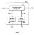
- FIG. 3 shows a representation of the optical switching logic 210 in accordance with an embodiment of the present invention.
- FIG. 3 shows an embodiment of optical switching logic 210 having one OADM 310, one optical receiver 340, and one optical transmitter 350.
- the optical switching logic 210 may (and typically does) include multiple OADMs, multiple optical receivers, and multiple optical transmitters.
- the OADM 310 is coupled to one of the incoming optical interface(s) 110 for processing incoming optical data streams received over a single incoming optical fiber and to one of the outgoing optical interface(s) 130 for outputting optical data streams over a single outgoing optical fiber.
- the OADM 310 demultiplexes a number of incoming optical data streams from the incoming optical fiber. For each individual incoming optical data stream, the OADM 310 can be configured to either pass the incoming optical data stream through to the outgoing optical fiber via the outgoing optical interface 130 or "drop" the incoming optical data stream to the optical receiver 340 over the interface 320.
- the optical receiver 340 which acts as a termination point for a "dropped” optical data stream, converts the "dropped" optical data stream into a digital format and forwards the converted optical data stream to the routing logic 240 over the interface 220.
- the optical transmitter 350 receives forwarded information from the routing logic 240 over the interface 230.
- the optical transmitter 350 converts the forwarded information from a digital format into an optical data stream at a predetermined wavelength and forwards the optical data stream to the OADM 310 over the interface 330.
- the OADM 310 "adds" the optical data stream to the outgoing optical fiber via the outgoing optical interface 130.
- the OADM 310 can use any of a number of technologies for dropping and adding optical data streams.
- a typical OADM 310 includes at least a demultiplexer for demultiplexing the incoming optical data streams from the incoming optical fiber, some means for dropping one or more optical data streams, and some means for adding one or more optical data streams.
- Various embodiments of an OADM 310 are described in the related application entitled SYSTEM, DEVICE, AND METHOD FOR DROPPING AND ADDING OPTICAL DATA STREAMS IN AN OPTICAL COMMUNICATION NETWORK, which was incorporated by reference above. Two exemplary embodiments of an OADM 310 are described below with reference to FIGs. 4-5 . It should be noted, however, that the present invention is in no way limited by the technology for dropping and adding optical data streams by the OADM 310.
- FIG. 4 shows an embodiment of an OADM 310 that includes a demultiplexer 410, an optical add/drop fabric 420, and a multiplexer 430.
- the demultiplexer 410 is coupled to the incoming optical interface 110 for processing incoming optical data streams received over the incoming optical fiber 110.
- the demultiplexer 410 demultiplexes a number of incoming optical data streams from the incoming optical fiber 110, and outputs the demultiplexed optical data streams to the optical add/drop fabric 420.
- the optical add/drop fabric 420 receives optical data streams from the demultiplexer 410 and also receives any "added" optical data streams from the interface 330. For each optical data stream received from the demultiplexer 410, the optical add/drop fabric 420 can be configured to either pass the optical data stream through to the multiplexer 430 or "drop" the incoming optical data stream to the optical receiver 340 over the interface 320. The optical add/drop fabric 420 can also be configured to output the "added” optical data streams to the multiplexer 430. Due to the operation of the optical add/drop fabric 420, the "added" optical data streams are typically limited to the wavelengths of the "dropped" optical data streams.
- the multiplexer 430 receives optical data streams of different wavelengths from the optical add/drop fabric 420.
- the multiplexer 430 combines the various optical data streams onto a single optical fiber over the outgoing optical interface 130.
- the optical add/drop fabric 420 is a Micro Electro Mechanical System (MEMS) that includes double-sided mirrors or double mirror combinations for selectively passing, dropping, and adding optical data streams at various wavelengths.
- MEMS Micro Electro Mechanical System
- MOEMS Micro Opto Electro Mechanical System
- bubble (champagne) technology lithium niobate technology
- liquid crystal technology or other optical/photonic switching technology.
- FIG. 5 shows an embodiment of an OADM 310 that includes a demultiplexer 510, an optical drop-only fabric 520, and an external combiner 530.
- the demultiplexer 510 is coupled to the incoming optical interface 110 for processing incoming optical data streams received over the incoming optical fiber 110.
- the demultiplexer 510 demultiplexes a number of incoming optical data streams from the incoming optical fiber 110, and outputs the demultiplexed optical data streams to the optical drop-only fabric 520.
- the optical drop-only fabric 520 receives optical data streams from the demultiplexer 510. For each optical data stream received from the demultiplexer 510, the optical drop-only fabric 520 can be configured to either pass the optical data stream through to the external combiner 530 or "drop" the incoming optical data stream to the optical receiver 340 over the interface 320.
- the external combiner 530 receives optical data streams from the optical drop-only fabric 520 and also receives any "added” optical data streams from the interface 330.
- the external combiner 530 combines the various optical data streams onto a single outgoing optical fiber over the outgoing optical interface 130. Because the "added" optical data streams are added to the optical communication path outside of the optical drop-only fabric 520, the “added” optical data streams are typically not limited to the wavelengths of the "dropped" optical data streams.
- the optical drop-only fabric 520 is a Micro Electro Mechanical System (MEMS) that includes single-sided mirrors for selectively passing and dropping optical data streams at various wavelengths.
- MEMS Micro Electro Mechanical System
- MOEMS Micro Opto Electro Mechanical System
- bubble (champagne) technology lithium niobate technology
- liquid crystal technology or other optical/photonic switching technology.
- the optical receiver 340 is coupled to receive a "dropped" optical data stream at a particular wavelength from the OADM 310 over the interface 320.
- the optical receiver 340 acts as a termination point for the "dropped” optical data stream.
- the optical receiver 340 converts the "dropped" optical data stream into a digital format and forwards the converted optical data stream to the routing logic 240 over the interface 220.
- FIG. 6 shows a representation of the optical receiver 340.
- the optical receiver 340 includes an optical-to-digital converter 610 and a receiver ASIC (Application Specific Integrated Circuit) 620.
- the optical-to-digital converter 610 converts the "dropped" optical data stream into a digital data stream and forwards the digital data stream to the receiver ASIC 620 over the interface 630.
- the receiver ASIC includes logic for receiving the digital data stream over the interface 630, processing the digital data stream, and forwarding the processed digital data stream to the routing logic 240 over the interface 220.
- the optical transmitter 350 is coupled to the interface 230 for receiving forwarded information from the routing logic 240.
- the optical transmitter 350 converts the forwarded information received from the routing logic 240 over the interface 230 from a digital format into an optical data stream at a predetermined wavelength and forwards the optical data stream to the OADM 310 over the interface 330.
- FIG. 7 shows a representation of the optical transmitter 350.
- the optical transmitter 350 includes a digital-to-optical converter 710 and a transmitter ASIC (Application Specific Integrated Circuit) 720.
- the transmitter ASIC 720 includes logic for processing the forwarded information received from the routing logic 240 over the interface 230 and forwarding the processed information to the digital-to-optical converter 710 over the interface 730.
- the digital-to-optical converter 710 receives the forwarded information over the interface 730, converts the forwarded information from a digital format into an optical data stream at a predetermined wavelength, and forwards the optical data stream to the OADM 310 over the interface 330.
- the digital-to-optical converter 710 can use any of a variety of technologies for producing the optical data stream at the predetermined wavelength.
- a typical digital-to-optical converter 710 includes a laser for producing an optical carrier at the predetermined wavelength and an external modulator for modulating the optical carrier based upon the digital information.
- Various embodiments for producing a optical data stream at a predetermined wavelength are described in the related application entitled SYSTEM, DEVICE, AND METHOD FOR PRODUCING OPTICAL DATA STREAMS IN AN OPTICAL COMMUNICATION NETWORK, which was incorporated by reference above.
- Three exemplary embodiments of a digital-to-optical converter 710 are described below with reference to FIGs. 8-10 . It should be noted, however, that the present invention is in no way limited by the way in which optical data streams are produced by the optical transmitter 350.
- FIG. 8 shows an embodiment of a digital-to-optical converter 710 that employs a tunable (agile) laser to produce the optical data stream at the predetermined wavelength.
- the digital-to-optical converter 710 includes a tunable laser 810 and an external modulator 820.
- the tunable laser 810 is tunable to any of a number of wavelengths, and is tuned to the predetermined wavelength in order to produce an optical carrier at the predetermined wavelength.
- the external modulator 820 is coupled to receive the optical carrier from the tunable laser 810 and to receive the forwarded information from the interface 730.
- the external modulator 820 modulates the optical carrier based upon the forwarded information in order to produce the optical data stream at the predetermined wavelength and forward the optical data stream to the OADM 310 over the interface 330.
- FIG. 9 shows an embodiment of a digital-to-optical converter 710 that employs fixed wavelength lasers and digital switching to produce the optical data stream at the predetermined wavelength.
- the digital-to-optical converter 710 includes N fixed wavelength lasers 920 1 -920 N coupled respectively to N external modulators 930 1 -930 N . Each laser/modulator pair is capable of producing an optical data stream at one and only one wavelength.
- a digital switch 910 routes the forwarded information from the interface 730 to the external modulator of the laser/modulator pair at the predetermined wavelength.
- the external modulator modulates the optical carrier based upon the forwarded information in order to produce the optical data stream at the predetermined wavelength and forward the optical data stream to the OADM 310 over the interface 330.
- FIG.10 shows an embodiment of a digital-to-optical converter 710 that employs fixed wavelength lasers and photonic switching to produce the optical data stream at the predetermined wavelength.
- the digital-to-optical converter 710 includes M fixed wavelength lasers 1010 1 -1010 M and an external modulator 1030. Each fixed wavelength laser is capable of producing an optical carrier at one and only one wavelength.
- a photonic switch 1020 routes the optical carrier from the fixed wavelength laser having the predetermined wavelength to the external modulator 1030.
- the external modulator 1030 modulates the optical carrier based upon the forwarded information received over the interface 730 in order to produce the optical data stream at the predetermined wavelength and forward the optical data stream to the OADM 310 over the interface 330.
- optical switching logic is implemented as an optical line card that can be installed in a router. Multiple optical line cards may be installed in a router. Each optical line card interfaces with an optical network through an optical physical (PHY) card in the router.
- the optical PHY card typically includes at least incoming and outgoing optical interfaces for coupling with incoming and outgoing optical fiber(s), respectively.
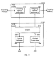
- FIG. 11 shows representation of an optical PHY card 1110 and an optical line card 1120 for use in an optical switch router.
- the optical PHY card 1110 includes, among other things, a number of incoming optical interfaces 110 and a number of outgoing optical interfaces 130 for interfacing the optical line card 1120 to an optical network.
- the optical line card 1120 includes, among other things, the OADM 310, the optical receiver 340, and the optical transmitter 350.
- optical receiver 340 and the optical transmitter 350 may be placed on the optical PHY card 1110 rather than the optical line card 1120, for example, to make room for additional components on the optical line card 1120.
- the optical PHY card 1110 may include additional optical interfaces for interfacing to other optical PHY cards and to other optical line cards within the router.
- the configuration of components on the optical PHY card 1110 and the optical line card 1120 depend on a number of factors including, but not limited to, the size of cards, the type of components (e.g., fixed wavelength lasers versus tunable lasers, digital switches versus photonic switches), the size of the components, the number of fibers supported, the number of optical data streams per fiber, the optical line rate (i.e., the data rate of each optical data stream), the frequency spacing of optical data streams on each fiber, the number of optical data streams that can be dropped and added, and the cost of the components, to name but a few.
- the size of cards e.g., the type of components (e.g., fixed wavelength lasers versus tunable lasers, digital switches versus photonic switches), the size of the components, the number of fibers supported, the number of optical data streams per fiber, the optical line rate (i.e., the data rate of each optical data stream), the frequency spacing of optical data streams on each fiber, the number of optical data streams that can be dropped and added,
- wavelength density i.e., number of optical data streams on an optical fiber
- optical line rates i.e., increased optical line rates
- wavelength spacing i.e., spacing between optical data streams on an optical fiber
- wavelength agility i.e., the ability to drop and/or add optical data streams at varying wavelengths rather than at fixed, predetermined wavelengths
- component costs generally increases the component costs.
- a convenient and cost-effective optical line card implementation supports two incoming optical fibers and two outgoing optical fibers, each having eight 10 Gb/s optical data streams spaced at 100 GHz.
- the number of optical data streams that can be dropped by the optical switching logic is typically limited to a maximum of two or four.
- Supporting two incoming optical fibers with a wavelength density of eight optical data streams per optical fiber typically provides for a less expensive implementation compared to, for example, a single incoming optical fiber having sixteen optical data streams. This is true even though two OADMs are needed, one for each incoming optical fiber, since, generally speaking, doubling the wavelength density (e.g., from eight to sixteen wavelengths on an optical fiber) typically triples the cost for components such as the optical demultiplexer/mulitiplexer. There is a small space premium to pay to support two optical fibers of eight wavelengths each rather than a single fiber with sixteen wavelengths.
- a typical sixteen wavelength multiplexer / demulitiplexer is approximately 4"x5", while a typical eight wavelength multiplexer/demultiplexer is approximately 3"x5".
- the 10 Gb/s line rate is convenient due to accelerating interest in 10 GbE (Gigabit Ethernet).
- other optical line rates such as a common line rate of 2.5 Gb/s can also be supported.
- the 100 GHz wavelength spacing typically provides for a less expensive implementation compared to, for example, a wavelength spacing of 50 GHz.
- the tighter wavelength spacing of 50 GHz is possible but more expensive, since optical mux/demux functions typically increase by a factor of 3 to 4 at 50 Ghz spacing over 100 Ghz spacing while only doubling the capacity of the optical fiber. Additionally, the cost of lasers would increase to meet the tighter wavelength stability requirements of 50 Ghz spacing. So by using 100 Ghz spacing and 10 Gb/s per channel, the aggregate bit rate is increase by a factor of 4 over 2.5 Gb/s while maintaining the lower cost wavelength spacing.
- the four exemplary embodiments are all based upon an implementation using two incoming optical fibers with eight 10 Gb/s optical data streams on each optical fiber spaced at 100 GHz, with an additional fiber input that is used in the event of a network/fiber fault on one of the primary fibers.
- the optical links are presumed to be short haul links.
- the optical components are presumed to be "pigtail" devices, and the space allowed for these pigtails is equal to the package size (which is an appropriate approximation for the smaller devices, but is an overly conservative approximation for the larger devices such as the optical mux/demux).
- the estimated cost for an optical receiver increases to $2,000 if long haul links are supported.
- two optical data streams can be dropped at the optical line card, one from each incoming fiber.
- the dropped wavelengths are fixed in that they can only be changed by manually disconnecting and reconnecting fibers outside of the demultiplexer and multiplexer.
- the component, cost, and space estimates for this embodiment are as follows: (2) 1x8 Optical Demux $16,000 (2) 3"x5" + pigtails 60 sq in (2) 8x1 Optical Mux $16,000 (2) 3"x5" + pigtails 60 sq in (2) 2x2 Optical Switch $ 600 (2) 1"x2" + pigtails 8 sq in (2) ITU Lasers + Modulator $ 8,000 (2) 2"x2" + pigtail 16 sq in (2) Optical Receiver $ 2,000 (2) 2"x2" + pigtail 16 sq in TOTAL: $42,600 160 sq in
- two optical data streams can be dropped at the optical line card, one from each incoming optical fiber.
- the dropped wavelengths are tunable, for example, under software control.
- the component, cost, and space estimates for this embodiment are as follows: (2) 1x8 Optical Demux $16,000 (2) 3"x5" + pigtails 60 sq in (2) 8x1 Optical Mux $16,000 (2) 3"x5" + pigtails 60 sq in (2) 2x2 Optical Switch $ 600 (2) 1"x2" + pigtails 8 sq in (16) 2x2 Optical Switch $ 4,800 (16) 1"x2" + pigtails 64 sq in (2) 1x2 Optical coupler $ 400 (2) 1"x2" + pigtails 8 sq in (2) Agile Lasers + Modulator $16,000 (2) 2"x2" + pigtail 16 sq in (1) Laser Control Circuit $ 200 (1) 2"x3" 6 sq in (2) Optical Receiver $ 2,000 (2) 2"x2" + pigtail 16 sq in (8) 8x1 Optical Switch $
- a maximum of four optical data streams can be dropped at the optical line card from either or both of the incoming optical fibers (e.g., three dropped from one fiber, one dropped from the other fiber).
- the dropped wavelengths are fixed in that they can only be changed by manually disconnecting and reconnecting fibers outside of the demultiplexer and multiplexer.
- the component, cost, and space estimates for this embodiment are as follows:.
- four optical data streams can be dropped at the optical line card, two from each incoming optical fiber.
- the dropped wavelengths are tunable, for example, under software control.
- the component, cost, and space estimates for this embodiment are as follows: (2) 1x8 Optical Demux $16,000 (2) 3"x5" + pigtail 60 sq in (2) 8x1 Optical Mux $16,000 (2) 3"x5" + pigtails 60 sq in (2) 2x2 Optical Switch $ 600 (2) 1"x2" + pigtails 8 sq in (16) 2x2 Optical Switch $ 4,800 (16) 1"x2" + pigtails 64 sq in (1) 1x2 Optical coupler $ 200 (1) 1"x2" + pigtails 4 sq in (1) 1x4 Optical coupler $ 200 (1) 1"x2" + pigtails 4 sq in (4) Agile Lasers + Modulator $32,000 (2) 2"x2" + pigtail 32 sq in (4) Laser Control Circuit $ 200 (2) 2"x3" 12 sq in (4) Optical Receiver
- the increase in cost and size for the optical portion of the line card is not substantial between adding/dropping two wavelengths versus add/dropping four wavelengths. Also, the increase in cost to use agile lasers is not great, but the increase in board space is significant. However, all four exemplary embodiments should be capable of fitting on a single optical line card. Therefore, whether a particular implementation supports a two dropped/added wavelengths or four dropped/added wavelengths and whether the dropped/added wavelengths are fixed or agile depends to a large degree on any additional circuitry/functions that are included on the optical line card. For example, if the termination circuitry for the 10 Gb/s data streams is included on the optical line card, then there will likely only be enough room for components supporting two dropped/added wavelengths. On the other hand, if the termination circuitry is placed elsewhere (for example, on another line card), then there should be enough room for components supporting four agile dropped/added wavelengths.
- component cost and size estimates are used for comparison purposes only. Actual component costs and sizes may be different, and may change. Historically, the costs and sizes of communication system components tend to decrease as the technology curve advances. Such decreases in cost and size may enable certain component configurations to fit on a single optical line card and/or be implemented in a more cost-effective manner. Thus, for example, with lower component costs and sizes, it may be possible to support more optical fibers, higher line rates, closer wavelength spacing, more dropped/added wavelengths, and/or additional circuitry/functions. Thus, the present invention is in no way limited to any particular implementation or implementations due to constraints imposed by component costs or sizes.
- optical switching logic 210 may perform a "drop” only function, an "add” only function, or both "drop” and “add” functions.
- various embodiments of the present invention may provide for dropping incoming optical data streams without adding new optical data streams to the outgoing fiber (i.e., "drop” only function), adding new optical data streams to the outgoing fiber without dropping optical data streams from the incoming optical fiber ("add" only function), or dropping and adding optical data streams.
- the present invention is not limited to any particular routing mechanism by which the routing logic 240 routes information.
- the routed information consists of IP packets that are routed based upon some routing protocol, such as RIP or OSPF.
- the present invention is not limited to these or to any other protocol(s).
- multiplexer and “combiner” are used herein for discussing two different embodiments of an optical add/drop multiplexer.
- a multiplexer is a combiner
- a combiner is a multiplexer, as both aggregate multiple optical data streams onto a single outgoing optical fiber.
- the present invention is in no way limited by the use of these terms.
- a communication device may include, without limitation, a bridge, router, bridge-router (brouter), switch, node, or other communication device.
- the present invention may be embodied in many different forms, including, but in no way limited to, computer program logic for use with a processor (e.g ., a microprocessor, microcontroller, digital signal processor, or general purpose computer), programmable logic for use with a programmable logic device (e.g ., a Field Programmable Gate Array (FPGA) or other PLD), discrete components, integrated circuitry (e.g ., an Application Specific Integrated Circuit (ASIC)), or any other means including any combination thereof.
- a processor e.g ., a microprocessor, microcontroller, digital signal processor, or general purpose computer
- programmable logic for use with a programmable logic device
- FPGA Field Programmable Gate Array
- ASIC Application Specific Integrated Circuit
- Source code may include a series of computer program instructions implemented in any of various programming languages (e.g., an object code, an assembly language, or a high-level language such as Fortran, C, C++, JAVA, or HTML) for use with various operating systems or operating environments.
- the source code may define and use various data structures and communication messages.
- the source code may be in a computer executable form ( e.g ., via an interpreter), or the source code may be converted ( e.g ., via a translator, assembler, or compiler) into a computer executable form.
- the computer program may be fixed in any form (e.g ., source code form, computer executable form, or an intermediate form) either permanently or transitorily in a tangible storage medium, such as a semiconductor memory device (e.g ., a RAM, ROM, PROM, EEPROM, or Flash-Programmable RAM), a magnetic memory device (e.g ., a diskette or fixed disk), an optical memory device (e.g ., a CD-ROM), a PC card (e.g ., PCMCIA card), or other memory device.
- a semiconductor memory device e.g ., a RAM, ROM, PROM, EEPROM, or Flash-Programmable RAM
- a magnetic memory device e.g ., a diskette or fixed disk
- an optical memory device e.g ., a CD-ROM
- PC card e.g ., PCMCIA card
- the computer program may be fixed in any form in a signal that is transmittable to a computer using any of various communication technologies, including, but in no way limited to, analog technologies, digital technologies, optical technologies, wireless technologies (e.g ., Bluetooth), networking technologies, and internetworking technologies.
- the computer program may be distributed in any form as a removable storage medium with accompanying printed or electronic documentation (e.g ., shrink wrapped software), preloaded with a computer system (e.g ., on system ROM or fixed disk), or distributed from a server or electronic bulletin board over the communication system (e.g ., the Internet or World Wide Web).
- Hardware logic including programmable logic for use with a programmable logic device
- implementing all or part of the functionality previously described herein may be designed using traditional manual methods, or may be designed, captured, simulated, or documented electronically using various tools, such as Computer Aided Design (CAD), a hardware description language (e.g ., VHDL or AHDL), or a PLD programming language (e.g., PALASM, ABEL, or CUPL).
- CAD Computer Aided Design
- a hardware description language e.g ., VHDL or AHDL
- PLD programming language e.g., PALASM, ABEL, or CUPL
- Programmable logic may be fixed either permanently or transitorily in a tangible storage medium, such as a semiconductor memory device (e.g., a RAM, ROM, PROM, EEPROM, or Flash-Programmable RAM), a magnetic memory device (e.g., a diskette or fixed disk), an optical memory device (e.g ., a CD-ROM), or other memory device.
- a semiconductor memory device e.g., a RAM, ROM, PROM, EEPROM, or Flash-Programmable RAM
- a magnetic memory device e.g., a diskette or fixed disk
- an optical memory device e.g ., a CD-ROM
- the programmable logic may be fixed in a signal that is transmittable to a computer using any of various communication technologies, including, but in no way limited to, analog technologies, digital technologies, optical technologies, wireless technologies (e.g., Bluetooth), networking technologies, and internetworking technologies.
- the programmable logic may be distributed as a removable storage medium with accompanying printed or electronic documentation (e.g., shrink wrapped software), preloaded with a computer system (e.g., on system ROM or fixed disk), or distributed from a server or electronic bulletin board over the communication system (e.g., the Internet or World Wide Web).
- printed or electronic documentation e.g., shrink wrapped software
- a computer system e.g., on system ROM or fixed disk
- server or electronic bulletin board e.g., the Internet or World Wide Web
- the optical switching logic may be operably coupled to receive an incoming optical data stream from an incoming optical fiber over an incoming optical interface and selectively pass the incoming optical data stream through to an outgoing optical fiber over an outgoing optical interface or divert the incoming optical data stream for processing by the routing logic.
- the optical switching logic may comprise a demultiplexer operably coupled to demultiplex the incoming optical data stream from a number of incoming optical data streams received from the incoming optical fiber over the incoming optical interface.
- the optical switching logic may further comprise an optical switch perably coupled to receive the incoming optical data stream from the demultiplexer and to selectively pass the incoming optical data stream through to the outgoing optical fiber over the outgoing optical interface or divert the incoming optical data stream for processing by the routing logic.
- the optical switch may comprise an optical add/ drop fabric.
- the optical switch may comprise an optical drop-only fabric.
- the optical switching logic may further comprise an optical receiver operably coupled to receive the diverted incoming optical data stream from the optical switch and convert the diverted incoming optical data stream into incoming digitally formatted information for processing by the routing logic.
- the routing logic may be operably coupled to receive the incoming digitally formatted information from the optical receiver and route the incoming digitally formatted information based upon a routing mechanism.
- the routing logic may be operably coupled to forward outgoing digitally formatted information to the optical switching logic for forwarding to an outgoing optical fiber over an outgoing optical interface.
- the optical switching logic may be operably coupled to receive the outgoing digitally formatted information from the routing logic and output an outgoing optical data stream to the outgoing optical fiber over the outgoing optical interface.
- the optical switching logic may comprise an optical transmitter operably coupled to receive the outgoing digitally formatted information from the routing logic and produce the outgoing optical data stream from the digitally formatted information at a predetermined wavelength.
- the optical transmitter may comprise a fixed wavelength laser for producing the outgoing optical data stream at the predetermined wavelength.
- the optical transmitter may comprise a tunable laser tuned to produce the outgoing optical data stream at the predetermined wavelength.
- the optical switching logic may further comprise:
- the optical switch may comprise an optical add/ drop fabric.
- the optical switching logic may further comprise a combiner operably coupled to receive the outgoing optical data stream from the optical transmitter and add the outgoing optical data stream to the outgoing optical fiber over the outgoing optical interface.
- the networking device may be an optical switch router.
- a system comprising: optical switching logic coupled to a number of optical interfaces for sending or receiving an optical data stream over at least one optical fiber; and routing logic operably coupled to the optical switching logic and to a number of ports for routing information based upon a routing mechanism, wherein the optical switching logic and the routing logic interoperate to switch and route information for sending or receiving the optical data stream over the at least one optical fiber.
- the optical switching logic may be operably coupled to receive an incoming optical data stream from an incoming optical fiber over an incoming optical interface and selectively pass the incoming optical data stream through to an outgoing optical fiber over an outgoing optical interface or divert the incoming optical data stream for processing by the routing logic.
- the optical switching logic may comprise a demultiplexer operably coupled to demultiplex the incoming optical data stream from a number of incoming optical data streams received from the incoming optical fiber over the incoming optical interface.
- the optical switching logic may further comprise an optical switch operably coupled to receive the incoming optical data stream from the demultiplexer and to selectively pass the incoming optical data stream through to the outgoing optical fiber over the outgoing optical interface or divert the incoming optical data stream for processing by the routing logic.
- the optical switch may comprise an optical add/ drop fabric.
- the optical switch may comprise an optical drop-only fabric.
- the optical switching logic may further comprise an optical receiver operably coupled to receive the diverted incoming optical data stream from the optical switch and convert the diverted incoming optical data stream into incoming digitally formatted information for processing by the routing logic.
- the routing logic may be operably coupled to receive the incoming digitally formatted information from the optical receiver and route the incoming digitally formatted information based upon a routing mechanism.
- the routing logic may be operably coupled to forward outgoing digitally formatted information to the optical switching logic for forwarding to an outgoing optical fiber over an outgoing optical interface.
- the optical switching logic may be operably coupled to receive the outgoing digitally formatted information from the routing logic and output an outgoing optical data stream to the outgoing optical fiber over the outgoing optical interface.
- the optical switching logic may comprise an optical transmitter operably coupled to receive the outgoing digitally formatted information from the routing logic and produce the outgoing optical data stream from the digitally formatted information at a predetermined wavelength.
- the optical transmitter may comprise a fixed wavelength laser for producing the outgoing optical data stream at the predetermined wavelength.
- the optical transmitter may comprise a tunable laser tuned to produce the outgoing optical data stream at the predetermined wavelength.
- the optical switching logic may further comprise: an optical switch operably coupled to receive the outgoing optical data stream from the optical transmitter; and a multiplexer operably coupled to receive the outgoing optical data stream from the optical switch and add the outgoing optical data stream to the outgoing optical fiber over the outgoing optical interface.
- the optical switch may comprise an optical add/ drop fabric.
- the optical switching logic may further comprise a combiner operably coupled to receive the outgoing optical data stream from the optical transmitter and add the outgoing optical data stream to the outgoing optical fiber over the outgoing optical interface.
- the system may be an optical switching/routing system.
- An optical line card for use in a networking device, the optical line card comprising: a router interface; and optical switching logic operably coupled to receive an incoming optical data stream from an incoming optical fiber over an incoming optical interface and selectively pass the incoming optical data stream through to an outgoing optical fiber over an outgoing optical interface or divert the incoming optical data stream over the router interface for processing by routing logic.
- the optical switching logic may comprise a demultiplexer operably coupled to demultiplex the incoming optical data stream from a number of incoming optical data streams received from the incoming optical fiber over the incoming optical interface.
- the optical switching logic may further comprise an optical switch operably coupled to receive the incoming optical data stream from the demultiplexer and to selectively pass the incoming optical data stream through to the outgoing optical fiber over the outgoing optical interface or divert the incoming optical data stream over the router interface for processing by the routing logic.
- the optical switch may comprise an optical add/drop fabric.
- the optical switch may comprise an optical drop-only fabric.
- the optical switching logic may further comprise an optical receiver operably coupled to receive the diverted incoming optical data stream from the optical switch and convert the diverted incoming optical data stream into incoming digitally formatted information for processing by the routing logic.
- the routing logic may be operably coupled to receive the incoming digitally formatted information from the optical receiver and route the incoming digitally formatted information based upon a routing mechanism.
- the optical switching logic may be operably coupled to receive outgoing digitally formatted information from the routing logic over the router interface and output an outgoing optical data stream to the outgoing optical fiber over the outgoing optical interface.
- the optical switching logic may comprise an optical transmitter operably coupled to receive the outgoing digitally formatted information from the routing logic over the router interface and produce the outgoing optical data stream from the digitally formatted information at a predetermined wavelength.
- the optical transmitter may comprise a fixed wavelength laser for producing the outgoing optical data stream at the predetermined wavelength.
- the optical transmitter may comprise a tunable laser tuned to produce the outgoing optical data stream at the predetermined wavelength.
- the optical switching logic may further comprise: an optical switch operably coupled to receive the outgoing optical data stream from the optical transmitter; and a multiplexer operably coupled to receive the outgoing optical data stream from the optical switch and add the outgoing optical data stream to the outgoing optical fiber over the outgoing optical interface.
- the optical switch may comprise an optical add/ drop fabric.
- the optical switching logic may further comprise a combiner operably coupled to receive the outgoing optical data stream from the optical transmitter and add the outgoing optical data stream to the outgoing optical fiber over the outgoing optical interface.
- the incoming optical interface and the outgoing optical interface may be on an optical physical card, and wherein the optical line card further comprises a physical card interface for coupling the optical switching logic to the incoming optical interface and the outgoing optical interface.
- a method for multicasting in an optical communication system comprising: receiving an optical data stream including multicast traffic; terminating the optical data stream; and routing the multicast traffic using a predetermined multicast routing mechanism.
- the receiving the optical data stream including multicast traffic may comprise: receiving the optical data stream over an incoming optical fiber.
- the terminating the optical data stream may comprise: dropping the optical data stream from the incoming optical fiber; and converting the multicast traffic from an optical form into a digital form suitable for routing.
Abstract
Description
- The present application may be related to the following commonly-owned United States patent applications, which are hereby incorporated herein by reference in their entireties:
- United States Patent Application No.
09/740,705 - United States Patent Application No.
09/740,706 - United States Patent Application No. XX/XXX,XXX entitled SYSTEM AND DEVICE FOR PROVIDING COMMUNICATION SERVICES IN AN OPTICAL COMMUNICATION SYSTEM, which was filed on even date herewith in the names of Bruce A. Schofield, Indermohan S. Monga, and Stephen Suryaputra.
- The present invention relates generally to optical networking, and more particularly to an optical switch router.
- Optical communication facilities provide vast amounts of bandwidth for extremely high-speed communications. In an optical communication system, an optical fiber typically carries multiple optical data streams, with each optical data stream at a different wavelength. This is typically referred to as Wavelength Division Multiplexing (WDM).
- Unfortunately, devices that communicate over optical communication facilities are often unable to process information and otherwise operate at the extremely high speeds of the optical communication facilities. Therefore, optical communication signals are typically converted into electronic signals for processing by the devices, and are converted back into optical signals when necessary for transmitting the signals over the optical communication facilities. Such optical-to-electronic and electronic-to-optical signal conversions add substantial delay to communication paths and also add complexity to the devices.
- In accordance with one aspect of the invention, an optical switch router performs both optical switching and traditional routing. The optical switch router includes optical interfaces for coupling to one or more incoming optical fibers and to one or more outgoing optical fibers, and also includes a number of traditional router ports. Individual incoming optical data streams received over the incoming optical fiber(s) can be selectively passed through to one or more of the outgoing optical fibers or "dropped" from the optical communication path for traditional routing. Routed traffic, which can be received over the router ports or from the "dropped" optical data streams, can be forwarded over optical data streams that are "added" to the outgoing optical fiber(s). The "added" optical data streams may be added to the outgoing optical fiber(s) at any unused wavelengths, including, but not limited to, the wavelengths of the "dropped" optical data streams.
- One advantage of such an optical switch router over a traditional router is that the optical switch router does not perform optical-electrical-optical conversions in order to pass an optical data stream through from an incoming optical fiber to an outgoing optical fiber. Instead, the optical data stream is passed through unchanged in optical form. This essentially eliminates any processing by the optical switch router for optical data streams that are passed through.
- Another advantage of such an optical switch router over a traditional router is that the optical switch router can automatically and dynamically switch between passing through an incoming optical data stream and dropping the incoming optical data stream for local processing by the optical switch router. Thus, the optical switch router can pass through an optical data stream during one period of time and drop the optical data stream for local processing during another period of time. The optical switch router only needs to convert an optical data stream from optical form into electrical form during that period that the optical data stream is being dropped for local processing by the optical switch router.
- Other aspects and advantages of the present invention will become apparent from the following disclosure.
- In the accompanying drawings:
-
FIG.1 is a block diagram showing relevant components of an optical switch router in accordance with an embodiment of the present invention; -
FIG. 2 is a block diagram showing relevant components of the switching/routing logic of the optical switch router in accordance with an embodiment of the present invention; -
FIG. 3 is a block diagram showing relevant components of the optical switching logic of the switching/routing logic of the optical switch router in accordance with an embodiment of the present invention; -
FIG. 4 is a block diagram showing an optical add/drop multiplexer that includes an optical add/drop fabric in accordance with an embodiment of the present invention; -
FIG. 5 is a block diagram showing an optical add/drop multiplexer that include an optical drop-only fabric with external combiner in accordance with an embodiment of the present invention; -
FIG. 6 is a block diagram showing relevant components of an optical receiver in accordance with an embodiment of the present invention; -
FIG. 7 is a block diagram showing relevant components of an optical transmitter in accordance with an embodiment of the present invention; -
FIG. 8 is a block diagram showing a digital-to-optical converter that employs a tunable (agile) laser to produce an optical data stream at a predetermined wavelength in accordance with an embodiment of the present invention; -
FIG. 9 is a block diagram showing a digital-to-optical converter that employs fixed wavelength lasers and digital switching to produce an optical data stream at a predetermined wavelength in accordance with an embodiment of the present invention; -
FIG. 10 is a block diagram showing a digital-to-optical converter that employs fixed wavelength lasers and photonic switching to produce an optical data stream at a predetermined wavelength in accordance with an embodiment of the present invention; and -
FIG. 11 is a block diagram showing relevant components of an optical PHY card and an optical line card for use in an optical switch router in accordance with an embodiment of the present invention. - In an embodiment of the invention, an optical switch router performs both optical switching and traditional routing. The optical switch router includes optical interfaces for coupling to one or more incoming optical fibers and to one or more outgoing optical fibers, and also includes a number of traditional router ports. Individual incoming optical data streams received over the incoming optical fiber(s) can be selectively passed through to one or more of the outgoing optical fibers or "dropped" from the optical communication path for traditional routing. Routed traffic, which can be received over the router ports or from the "dropped" optical data streams, can be forwarded over optical data streams that are "added" to the outgoing optical fiber(s). The "added" optical data streams may be added to the outgoing optical fiber(s) at any unused wavelengths, including, but not limited to, the wavelengths of the "dropped" optical data streams.
-
FIG. 1 shows a representation of an optical switch router 100 in accordance with an embodiment of the present invention. Among other things, the optical switch router 100 includes one or more incoming optical interface(s) 110, switching/routing logic 120, one or more outgoing optical interface(s) 130, and a number ofrouter ports 140. The optical switch router 100 is couplable to one or more incoming optical fibers via the incoming optical interface(s) 110 for receiving optical data streams at various wavelengths. The optical switch router 100 is also couplable to one or more outgoing optical fibers via the outgoing optical interface(s) 130 for outputting optical data streams at various wavelengths. The switching/routing logic 120 is coupled between the incoming optical interface(s) 110 and the outgoing optical interface(s) 130, and is also coupled to therouter ports 140. The switching/routing logic 120 includes optical switching logic as well as traditional routing logic. For each individual incoming optical data stream received via the incoming optical interface(s) 110, the switching/routing logic 120 can be dynamically configured to either pass the incoming optical data stream through to the outgoing optical fiber(s) via the outgoing optical interface(s) 130 or "drop" the incoming optical data stream from the optical communication path for traditional routing. The switching/routing logic 120 obtains routable information, such as Internet Protocol (IP) packets, from the "dropped" optical data stream(s) as well as from therouter ports 140, and forwards the routable information using traditional routing techniques. The switching/routing logic 120 can forward the routed information over therouter ports 140 and/or over one or more optical data streams "added" to the outgoing optical fiber(s) via the outgoing optical interface(s) 130. The "added" optical data stream(s) may be added to the outgoing optical fiber(s) at any unused wavelength(s), including, but not limited to, the wavelength(s) of the "dropped" optical data stream(s). -
FIG. 2 shows a representation of the switching/routing logic 120 in accordance with an embodiment of the present invention. Among other things, the switching/routing logic 120 includesoptical switching logic 210 androuting logic 240. Theoptical switching logic 210 is coupled between the incoming optical interface(s) 110 and the outgoing optical interface(s) 130. For each individual incoming optical data stream received via the incoming optical interface(s) 110, theoptical switching logic 210 can be dynamically configured to either pass the incoming optical data stream through to the outgoing optical fiber(s) via the outgoing optical interface(s) 130 or "drop" the incoming optical data stream to therouting logic 240 over theinterface 220. Therouting logic 240 obtains routable information, such as IP packets, from the "dropped" optical data stream(s) received from theoptical switching logic 210 over theinterface 220 as well as from therouter ports 140, and forwards the routable information using traditional routing techniques. Therouting logic 240 can forward the routed information over therouter ports 140 and/or to theoptical switching logic 210 over theinterface 230 for transmission by theoptical switching logic 210 over one or more optical data streams "added" to the outgoing optical fiber(s) via the outgoing optical interface(s) 130. The "added" optical data stream(s) may be added to the outgoing optical fiber(s) at any unused wavelength(s), including, but not limited to, the wavelength(s) of the "dropped" optical data stream(s). - Optical switching (i.e., dropping and/or adding optical data streams) can be done for any of a variety of reasons. For example, a particular optical data stream may be "dropped" for processing by the
routing logic 240 in order to implement multicasting, in which case the incoming optical data stream is terminated by theoptical switching logic 210 and multicast traffic is routed by therouting logic 240 according to a predetermined multicast routing mechanism (e.g., PIM). The present invention is in no way limited by the reason for optical switching. - Dynamic configuration of the
optical switching logic 210 can be done for any of a variety of reasons. For example, theoptical switching logic 210 may be dynamically configured based upon network conditions (e.g., route changes caused by node/link failures, traffic volume, congestion), cost concerns, application requirements, or other end-user requirements, to name but a few. The present invention is in no way limited by the reason for dynamic configuration of theoptical switching logic 210. - Dynamic configuration of the
optical switching logic 210 can be accomplished using any of a variety of mechanisms. For one example, theoptical switching logic 210 may be dynamically configured under control of therouting logic 240, particularly as network routes change pursuant to a routing protocol, such as Routing Information Protocol (RIP) or Open Shortest Path First (OSPF). For another example, theoptical switching logic 210 may be dynamically configured under control of a management agent (not shown). The present invention is in no way limited by the mechanism by which dynamic configuration of theoptical switching logic 210 is accomplished. - In a typical embodiment of the present invention, the
optical switching logic 210 includes a number of optical add/drop multiplexers (OADM). Each OADM is typically coupled to one of the incoming optical interface(s) 110 for processing incoming optical data streams received over a single incoming optical fiber and to one of the outgoing optical interface(s) 130 for outputting optical data streams over a single outgoing optical fiber. In order to process the incoming optical data streams received over the single incoming optical fiber, the OADM typically demultiplexes the incoming optical data streams from the incoming optical fiber. The OADM is configured to pass through certain of the incoming optical data streams to the outgoing optical fiber and to "drop" one or more of the incoming optical data streams from the optical communication path for traditional routing. Each "dropped" optical data stream is sent to an optical receiver, which converts the optical data stream into a digital format and forwards the digital information to therouting logic 240. Theoptical switching logic 210 receives a number of digital data streams from therouting logic 240 for forwarding as outgoing optical data streams over one or more outgoing optical fibers. Each digital data stream received from therouting logic 240 is processed by an optical transmitter, which converts the forwarded information from a digital format into an optical data stream at a predetermined wavelength and forwards the optical data stream to one of the OADMs. The OADM "adds" the optical data stream to the outgoing optical fiber. -
FIG. 3 shows a representation of theoptical switching logic 210 in accordance with an embodiment of the present invention. For the sake of simplicity,FIG. 3 shows an embodiment ofoptical switching logic 210 having oneOADM 310, oneoptical receiver 340, and oneoptical transmitter 350. It should be noted, however, that in various alternative embodiments of the present invention, theoptical switching logic 210 may (and typically does) include multiple OADMs, multiple optical receivers, and multiple optical transmitters. - As shown in
FIG. 3 , theOADM 310 is coupled to one of the incoming optical interface(s) 110 for processing incoming optical data streams received over a single incoming optical fiber and to one of the outgoing optical interface(s) 130 for outputting optical data streams over a single outgoing optical fiber. TheOADM 310 demultiplexes a number of incoming optical data streams from the incoming optical fiber. For each individual incoming optical data stream, theOADM 310 can be configured to either pass the incoming optical data stream through to the outgoing optical fiber via the outgoingoptical interface 130 or "drop" the incoming optical data stream to theoptical receiver 340 over theinterface 320. Theoptical receiver 340, which acts as a termination point for a "dropped" optical data stream, converts the "dropped" optical data stream into a digital format and forwards the converted optical data stream to therouting logic 240 over theinterface 220. Theoptical transmitter 350 receives forwarded information from therouting logic 240 over theinterface 230. Theoptical transmitter 350 converts the forwarded information from a digital format into an optical data stream at a predetermined wavelength and forwards the optical data stream to theOADM 310 over theinterface 330. TheOADM 310 "adds" the optical data stream to the outgoing optical fiber via the outgoingoptical interface 130. - The
OADM 310 can use any of a number of technologies for dropping and adding optical data streams. Atypical OADM 310 includes at least a demultiplexer for demultiplexing the incoming optical data streams from the incoming optical fiber, some means for dropping one or more optical data streams, and some means for adding one or more optical data streams. Various embodiments of anOADM 310 are described in the related application entitled SYSTEM, DEVICE, AND METHOD FOR DROPPING AND ADDING OPTICAL DATA STREAMS IN AN OPTICAL COMMUNICATION NETWORK, which was incorporated by reference above. Two exemplary embodiments of anOADM 310 are described below with reference toFIGs. 4-5 . It should be noted, however, that the present invention is in no way limited by the technology for dropping and adding optical data streams by theOADM 310. -
FIG. 4 shows an embodiment of anOADM 310 that includes ademultiplexer 410, an optical add/drop fabric 420, and amultiplexer 430. Thedemultiplexer 410 is coupled to the incomingoptical interface 110 for processing incoming optical data streams received over the incomingoptical fiber 110. Thedemultiplexer 410 demultiplexes a number of incoming optical data streams from the incomingoptical fiber 110, and outputs the demultiplexed optical data streams to the optical add/drop fabric 420. - The optical add/
drop fabric 420 receives optical data streams from thedemultiplexer 410 and also receives any "added" optical data streams from theinterface 330. For each optical data stream received from thedemultiplexer 410, the optical add/drop fabric 420 can be configured to either pass the optical data stream through to themultiplexer 430 or "drop" the incoming optical data stream to theoptical receiver 340 over theinterface 320. The optical add/drop fabric 420 can also be configured to output the "added" optical data streams to themultiplexer 430. Due to the operation of the optical add/drop fabric 420, the "added" optical data streams are typically limited to the wavelengths of the "dropped" optical data streams. - The
multiplexer 430 receives optical data streams of different wavelengths from the optical add/drop fabric 420. Themultiplexer 430 combines the various optical data streams onto a single optical fiber over the outgoingoptical interface 130. - In a typical embodiment of the present invention, the optical add/
drop fabric 420 is a Micro Electro Mechanical System (MEMS) that includes double-sided mirrors or double mirror combinations for selectively passing, dropping, and adding optical data streams at various wavelengths. However, the present invention is in no way limited to a MEMS. Rather, the optical add/drop fabric 420 can use any of a variety of technologies, including, but not limited to, Micro Electro Mechanical System (MEMS) technology, Micro Opto Electro Mechanical System (MOEMS) technology, bubble (champagne) technology, lithium niobate technology, liquid crystal technology, or other optical/photonic switching technology. -
FIG. 5 shows an embodiment of anOADM 310 that includes ademultiplexer 510, an optical drop-onlyfabric 520, and anexternal combiner 530. Thedemultiplexer 510 is coupled to the incomingoptical interface 110 for processing incoming optical data streams received over the incomingoptical fiber 110. Thedemultiplexer 510 demultiplexes a number of incoming optical data streams from the incomingoptical fiber 110, and outputs the demultiplexed optical data streams to the optical drop-onlyfabric 520. - The optical drop-only
fabric 520 receives optical data streams from thedemultiplexer 510. For each optical data stream received from thedemultiplexer 510, the optical drop-onlyfabric 520 can be configured to either pass the optical data stream through to theexternal combiner 530 or "drop" the incoming optical data stream to theoptical receiver 340 over theinterface 320. - The
external combiner 530 receives optical data streams from the optical drop-onlyfabric 520 and also receives any "added" optical data streams from theinterface 330. Theexternal combiner 530 combines the various optical data streams onto a single outgoing optical fiber over the outgoingoptical interface 130. Because the "added" optical data streams are added to the optical communication path outside of the optical drop-onlyfabric 520, the "added" optical data streams are typically not limited to the wavelengths of the "dropped" optical data streams. - In a typical embodiment of the present invention, the optical drop-only
fabric 520 is a Micro Electro Mechanical System (MEMS) that includes single-sided mirrors for selectively passing and dropping optical data streams at various wavelengths. However, the present invention is in no way limited to a MEMS. Rather, the optical add/drop fabric 420 can use any of a variety of technologies, including, but not limited to, Micro Electro Mechanical System (MEMS) technology, Micro Opto Electro Mechanical System (MOEMS) technology, bubble (champagne) technology, lithium niobate technology, liquid crystal technology, or other optical/photonic switching technology. - With reference again to
FIG. 3 , theoptical receiver 340 is coupled to receive a "dropped" optical data stream at a particular wavelength from theOADM 310 over theinterface 320. Theoptical receiver 340 acts as a termination point for the "dropped" optical data stream. Theoptical receiver 340 converts the "dropped" optical data stream into a digital format and forwards the converted optical data stream to therouting logic 240 over theinterface 220. -
FIG. 6 shows a representation of theoptical receiver 340. Among other things, theoptical receiver 340 includes an optical-to-digital converter 610 and a receiver ASIC (Application Specific Integrated Circuit) 620. The optical-to-digital converter 610 converts the "dropped" optical data stream into a digital data stream and forwards the digital data stream to thereceiver ASIC 620 over theinterface 630. The receiver ASIC includes logic for receiving the digital data stream over theinterface 630, processing the digital data stream, and forwarding the processed digital data stream to therouting logic 240 over theinterface 220. - With reference again to
FIG. 3 , theoptical transmitter 350 is coupled to theinterface 230 for receiving forwarded information from therouting logic 240. Theoptical transmitter 350 converts the forwarded information received from therouting logic 240 over theinterface 230 from a digital format into an optical data stream at a predetermined wavelength and forwards the optical data stream to theOADM 310 over theinterface 330. -
FIG. 7 shows a representation of theoptical transmitter 350. Among other things, theoptical transmitter 350 includes a digital-to-optical converter 710 and a transmitter ASIC (Application Specific Integrated Circuit) 720. Thetransmitter ASIC 720 includes logic for processing the forwarded information received from therouting logic 240 over theinterface 230 and forwarding the processed information to the digital-to-optical converter 710 over theinterface 730. The digital-to-optical converter 710 receives the forwarded information over theinterface 730, converts the forwarded information from a digital format into an optical data stream at a predetermined wavelength, and forwards the optical data stream to theOADM 310 over theinterface 330. - The digital-to-
optical converter 710 can use any of a variety of technologies for producing the optical data stream at the predetermined wavelength. A typical digital-to-optical converter 710 includes a laser for producing an optical carrier at the predetermined wavelength and an external modulator for modulating the optical carrier based upon the digital information. Various embodiments for producing a optical data stream at a predetermined wavelength are described in the related application entitled SYSTEM, DEVICE, AND METHOD FOR PRODUCING OPTICAL DATA STREAMS IN AN OPTICAL COMMUNICATION NETWORK, which was incorporated by reference above. Three exemplary embodiments of a digital-to-optical converter 710 are described below with reference toFIGs. 8-10 . It should be noted, however, that the present invention is in no way limited by the way in which optical data streams are produced by theoptical transmitter 350. -
FIG. 8 shows an embodiment of a digital-to-optical converter 710 that employs a tunable (agile) laser to produce the optical data stream at the predetermined wavelength. Among other things, the digital-to-optical converter 710 includes atunable laser 810 and anexternal modulator 820. Thetunable laser 810 is tunable to any of a number of wavelengths, and is tuned to the predetermined wavelength in order to produce an optical carrier at the predetermined wavelength. Theexternal modulator 820 is coupled to receive the optical carrier from thetunable laser 810 and to receive the forwarded information from theinterface 730. Theexternal modulator 820 modulates the optical carrier based upon the forwarded information in order to produce the optical data stream at the predetermined wavelength and forward the optical data stream to theOADM 310 over theinterface 330. -
FIG. 9 shows an embodiment of a digital-to-optical converter 710 that employs fixed wavelength lasers and digital switching to produce the optical data stream at the predetermined wavelength. Among other things, the digital-to-optical converter 710 includes N fixed wavelength lasers 9201-920N coupled respectively to N external modulators 9301-930N. Each laser/modulator pair is capable of producing an optical data stream at one and only one wavelength. Adigital switch 910 routes the forwarded information from theinterface 730 to the external modulator of the laser/modulator pair at the predetermined wavelength. The external modulator modulates the optical carrier based upon the forwarded information in order to produce the optical data stream at the predetermined wavelength and forward the optical data stream to theOADM 310 over theinterface 330. -
FIG.10 shows an embodiment of a digital-to-optical converter 710 that employs fixed wavelength lasers and photonic switching to produce the optical data stream at the predetermined wavelength. Among other things, the digital-to-optical converter 710 includes M fixed wavelength lasers 10101-1010M and anexternal modulator 1030. Each fixed wavelength laser is capable of producing an optical carrier at one and only one wavelength. Aphotonic switch 1020 routes the optical carrier from the fixed wavelength laser having the predetermined wavelength to theexternal modulator 1030. Theexternal modulator 1030 modulates the optical carrier based upon the forwarded information received over theinterface 730 in order to produce the optical data stream at the predetermined wavelength and forward the optical data stream to theOADM 310 over theinterface 330. - In a typical embodiment of the present invention, optical switching logic is implemented as an optical line card that can be installed in a router. Multiple optical line cards may be installed in a router. Each optical line card interfaces with an optical network through an optical physical (PHY) card in the router. The optical PHY card typically includes at least incoming and outgoing optical interfaces for coupling with incoming and outgoing optical fiber(s), respectively.
-
FIG. 11 shows representation of anoptical PHY card 1110 and anoptical line card 1120 for use in an optical switch router. In this example, theoptical PHY card 1110 includes, among other things, a number of incomingoptical interfaces 110 and a number of outgoingoptical interfaces 130 for interfacing theoptical line card 1120 to an optical network. Theoptical line card 1120 includes, among other things, theOADM 310, theoptical receiver 340, and theoptical transmitter 350. - It should be noted that the
optical receiver 340 and theoptical transmitter 350 may be placed on theoptical PHY card 1110 rather than theoptical line card 1120, for example, to make room for additional components on theoptical line card 1120. Also, theoptical PHY card 1110 may include additional optical interfaces for interfacing to other optical PHY cards and to other optical line cards within the router. - In various embodiments of the invention, the configuration of components on the
optical PHY card 1110 and theoptical line card 1120 depend on a number of factors including, but not limited to, the size of cards, the type of components (e.g., fixed wavelength lasers versus tunable lasers, digital switches versus photonic switches), the size of the components, the number of fibers supported, the number of optical data streams per fiber, the optical line rate (i.e., the data rate of each optical data stream), the frequency spacing of optical data streams on each fiber, the number of optical data streams that can be dropped and added, and the cost of the components, to name but a few. - Generally speaking, there is a trade-off between performance, cost, and component size. The cost and size of many of the components generally increases with increased wavelength density (i.e., number of optical data streams on an optical fiber), increased optical line rates, and decreased wavelength spacing (i.e., spacing between optical data streams on an optical fiber). Likewise, wavelength agility (i.e., the ability to drop and/or add optical data streams at varying wavelengths rather than at fixed, predetermined wavelengths) generally increases the component costs.
- Although the present invention is not limited to any particular wavelength density, optical line rate, or wavelength spacing, a convenient and cost-effective optical line card implementation supports two incoming optical fibers and two outgoing optical fibers, each having eight 10 Gb/s optical data streams spaced at 100 GHz. The number of optical data streams that can be dropped by the optical switching logic is typically limited to a maximum of two or four.
- Supporting two incoming optical fibers with a wavelength density of eight optical data streams per optical fiber typically provides for a less expensive implementation compared to, for example, a single incoming optical fiber having sixteen optical data streams. This is true even though two OADMs are needed, one for each incoming optical fiber, since, generally speaking, doubling the wavelength density (e.g., from eight to sixteen wavelengths on an optical fiber) typically triples the cost for components such as the optical demultiplexer/mulitiplexer. There is a small space premium to pay to support two optical fibers of eight wavelengths each rather than a single fiber with sixteen wavelengths. A typical sixteen wavelength multiplexer / demulitiplexer is approximately 4"x5", while a typical eight wavelength multiplexer/demultiplexer is approximately 3"x5". In addition, both need room for fiber pigtails to be curled up.
- The 10 Gb/s line rate is convenient due to accelerating interest in 10 GbE (Gigabit Ethernet). However, other optical line rates (such as a common line rate of 2.5 Gb/s) can also be supported.
- The 100 GHz wavelength spacing typically provides for a less expensive implementation compared to, for example, a wavelength spacing of 50 GHz. The tighter wavelength spacing of 50 GHz is possible but more expensive, since optical mux/demux functions typically increase by a factor of 3 to 4 at 50 Ghz spacing over 100 Ghz spacing while only doubling the capacity of the optical fiber. Additionally, the cost of lasers would increase to meet the tighter wavelength stability requirements of 50 Ghz spacing. So by using 100 Ghz spacing and 10 Gb/s per channel, the aggregate bit rate is increase by a factor of 4 over 2.5 Gb/s while maintaining the lower cost wavelength spacing.
- Four exemplary embodiments of the present invention are discussed below. The four exemplary embodiments are all based upon an implementation using two incoming optical fibers with eight 10 Gb/s optical data streams on each optical fiber spaced at 100 GHz, with an additional fiber input that is used in the event of a network/fiber fault on one of the primary fibers. The optical links are presumed to be short haul links. The optical components are presumed to be "pigtail" devices, and the space allowed for these pigtails is equal to the package size (which is an appropriate approximation for the smaller devices, but is an overly conservative approximation for the larger devices such as the optical mux/demux). Estimates of the hardware components, cost, and space requirements (excluding control and interface circuitry) are given for each of the four exemplary embodiments. The cost estimates are based upon the following component cost estimates:
1x8 Optical Demux $8,000 8x1 Optical Mux $8,000 2x2 Optical Switch $ 300 Fixed Laser + Modulator $4,000 Agile Laser + Modulator $8,000 Optical Receiver $1,000 - An agile (tunable) laser is presumed to be tunable within one second. Fast tuning typically costs substantially more, and it's added benefit is unclear.
- The estimated cost for an optical receiver increases to $2,000 if long haul links are supported.
- In a first exemplary embodiment, two optical data streams can be dropped at the optical line card, one from each incoming fiber. The dropped wavelengths are fixed in that they can only be changed by manually disconnecting and reconnecting fibers outside of the demultiplexer and multiplexer. The component, cost, and space estimates for this embodiment are as follows:
(2) 1x8 Optical Demux $16,000 (2) 3"x5" + pigtails 60 sq in (2) 8x1 Optical Mux $16,000 (2) 3"x5" + pigtails 60 sq in (2) 2x2 Optical Switch $ 600 (2) 1"x2" + pigtails 8 sq in (2) ITU Lasers + Modulator $ 8,000 (2) 2"x2" + pigtail 16 sq in (2) Optical Receiver $ 2,000 (2) 2"x2" + pigtail 16 sq in TOTAL: $42,600 160 sq in - In a second exemplary embodiment, two optical data streams can be dropped at the optical line card, one from each incoming optical fiber. The dropped wavelengths are tunable, for example, under software control. The component, cost, and space estimates for this embodiment are as follows:
(2) 1x8 Optical Demux $16,000 (2) 3"x5" + pigtails 60 sq in (2) 8x1 Optical Mux $16,000 (2) 3"x5" + pigtails 60 sq in (2) 2x2 Optical Switch $ 600 (2) 1"x2" + pigtails 8 sq in (16) 2x2 Optical Switch $ 4,800 (16) 1"x2" + pigtails 64 sq in (2) 1x2 Optical coupler $ 400 (2) 1"x2" + pigtails 8 sq in (2) Agile Lasers + Modulator $16,000 (2) 2"x2" + pigtail 16 sq in (1) Laser Control Circuit $ 200 (1) 2"x3" 6 sq in (2) Optical Receiver $ 2,000 (2) 2"x2" + pigtail 16 sq in (8) 8x1 Optical Switch $ 2,000 (2) 4"x4" + pigtails 32 sq in TOTAL: $58,000 270 sq in - In a third exemplary embodiment, a maximum of four optical data streams can be dropped at the optical line card from either or both of the incoming optical fibers (e.g., three dropped from one fiber, one dropped from the other fiber). The dropped wavelengths are fixed in that they can only be changed by manually disconnecting and reconnecting fibers outside of the demultiplexer and multiplexer. The component, cost, and space estimates for this embodiment are as follows:.
(2) 1x8 Optical Demux $16,000 (2) 3"x5" + pigtails 60 sq in (2) 8x1 Optical Mux $16,000 (2) 3"x5" + pigtails 60 sq in (2) 2x2 Optical Switch $ 600 (2) 1"x2" + pigtails 8 sq in (4) ITU Lasers + Modulator $16,000 (2) 2"x2" + pigtail 32 sq in (4) Optical Receiver $ 4,000 (2) 2"x2" + pigtail 32 sq in. TOTAL: $52,600 192 sq in - In a fourth exemplary embodiment, four optical data streams can be dropped at the optical line card, two from each incoming optical fiber. The dropped wavelengths are tunable, for example, under software control. The component, cost, and space estimates for this embodiment are as follows:
(2) 1x8 Optical Demux $16,000 (2) 3"x5" + pigtail 60 sq in (2) 8x1 Optical Mux $16,000 (2) 3"x5" + pigtails 60 sq in (2) 2x2 Optical Switch $ 600 (2) 1"x2" + pigtails 8 sq in (16) 2x2 Optical Switch $ 4,800 (16) 1"x2" + pigtails 64 sq in (1) 1x2 Optical coupler $ 200 (1) 1"x2" + pigtails 4 sq in (1) 1x4 Optical coupler $ 200 (1) 1"x2" + pigtails 4 sq in (4) Agile Lasers + Modulator $32,000 (2) 2"x2" + pigtail 32 sq in (4) Laser Control Circuit $ 200 (2) 2"x3" 12 sq in (4) Optical Receiver $ 4,000 (2) 2"x2" + pigtail 32 sq in (4) 8x1 Optical Switch $ 4,000 (4) 4"x4" + pigtail 64 sq in TOTAL: $74,000 340 sq in - Based upon these estimates, the increase in cost and size for the optical portion of the line card is not substantial between adding/dropping two wavelengths versus add/dropping four wavelengths. Also, the increase in cost to use agile lasers is not great, but the increase in board space is significant. However, all four exemplary embodiments should be capable of fitting on a single optical line card. Therefore, whether a particular implementation supports a two dropped/added wavelengths or four dropped/added wavelengths and whether the dropped/added wavelengths are fixed or agile depends to a large degree on any additional circuitry/functions that are included on the optical line card. For example, if the termination circuitry for the 10 Gb/s data streams is included on the optical line card, then there will likely only be enough room for components supporting two dropped/added wavelengths. On the other hand, if the termination circuitry is placed elsewhere (for example, on another line card), then there should be enough room for components supporting four agile dropped/added wavelengths.
- It should be noted that these component cost and size estimates are used for comparison purposes only. Actual component costs and sizes may be different, and may change. Historically, the costs and sizes of communication system components tend to decrease as the technology curve advances. Such decreases in cost and size may enable certain component configurations to fit on a single optical line card and/or be implemented in a more cost-effective manner. Thus, for example, with lower component costs and sizes, it may be possible to support more optical fibers, higher line rates, closer wavelength spacing, more dropped/added wavelengths, and/or additional circuitry/functions. Thus, the present invention is in no way limited to any particular implementation or implementations due to constraints imposed by component costs or sizes.
- It should be noted that, although the exemplary embodiments of the
optical switching logic 210 described above include an optical add/drop multiplexer 310 that performs both "drop" and "add" functions, the present invention is in no way limited to an optical add/drop multiplexer that performs both "drop" and "add" functions. Theoptical switching logic 210 may perform a "drop" only function, an "add" only function, or both "drop" and "add" functions. Thus, various embodiments of the present invention may provide for dropping incoming optical data streams without adding new optical data streams to the outgoing fiber (i.e., "drop" only function), adding new optical data streams to the outgoing fiber without dropping optical data streams from the incoming optical fiber ("add" only function), or dropping and adding optical data streams. - It should be noted that the present invention is not limited to any particular routing mechanism by which the
routing logic 240 routes information. In a typical embodiment of the present invention, the routed information consists of IP packets that are routed based upon some routing protocol, such as RIP or OSPF. However, the present invention is not limited to these or to any other protocol(s). - It should be noted that the terms "multiplexer" and "combiner" are used herein for discussing two different embodiments of an optical add/drop multiplexer. Within the context of the present invention, a multiplexer is a combiner, and a combiner is a multiplexer, as both aggregate multiple optical data streams onto a single outgoing optical fiber. The present invention is in no way limited by the use of these terms.
- It should be noted that terms such as "switch" and "router" are used herein to describe communication devices and communication functions that may be used in a communication system, and should not be construed to limit the present invention to any particular communication device type. Thus, a communication device may include, without limitation, a bridge, router, bridge-router (brouter), switch, node, or other communication device.
- The present invention may be embodied in many different forms, including, but in no way limited to, computer program logic for use with a processor (e.g., a microprocessor, microcontroller, digital signal processor, or general purpose computer), programmable logic for use with a programmable logic device (e.g., a Field Programmable Gate Array (FPGA) or other PLD), discrete components, integrated circuitry (e.g., an Application Specific Integrated Circuit (ASIC)), or any other means including any combination thereof.
- Computer program logic implementing all or part of the functionality previously described herein may be embodied in various forms, including, but in no way limited to, a source code form, a computer executable form, and various intermediate forms (e.g., forms generated by an assembler, compiler, linker, or locator). Source code may include a series of computer program instructions implemented in any of various programming languages (e.g., an object code, an assembly language, or a high-level language such as Fortran, C, C++, JAVA, or HTML) for use with various operating systems or operating environments. The source code may define and use various data structures and communication messages. The source code may be in a computer executable form (e.g., via an interpreter), or the source code may be converted (e.g., via a translator, assembler, or compiler) into a computer executable form.
- The computer program may be fixed in any form (e.g., source code form, computer executable form, or an intermediate form) either permanently or transitorily in a tangible storage medium, such as a semiconductor memory device (e.g., a RAM, ROM, PROM, EEPROM, or Flash-Programmable RAM), a magnetic memory device (e.g., a diskette or fixed disk), an optical memory device (e.g., a CD-ROM), a PC card (e.g., PCMCIA card), or other memory device. The computer program may be fixed in any form in a signal that is transmittable to a computer using any of various communication technologies, including, but in no way limited to, analog technologies, digital technologies, optical technologies, wireless technologies (e.g., Bluetooth), networking technologies, and internetworking technologies. The computer program may be distributed in any form as a removable storage medium with accompanying printed or electronic documentation (e.g., shrink wrapped software), preloaded with a computer system (e.g., on system ROM or fixed disk), or distributed from a server or electronic bulletin board over the communication system (e.g., the Internet or World Wide Web).
- Hardware logic (including programmable logic for use with a programmable logic device) implementing all or part of the functionality previously described herein may be designed using traditional manual methods, or may be designed, captured, simulated, or documented electronically using various tools, such as Computer Aided Design (CAD), a hardware description language (e.g., VHDL or AHDL), or a PLD programming language (e.g., PALASM, ABEL, or CUPL).
- Programmable logic may be fixed either permanently or transitorily in a tangible storage medium, such as a semiconductor memory device (e.g., a RAM, ROM, PROM, EEPROM, or Flash-Programmable RAM), a magnetic memory device (e.g., a diskette or fixed disk), an optical memory device (e.g., a CD-ROM), or other memory device. The programmable logic may be fixed in a signal that is transmittable to a computer using any of various communication technologies, including, but in no way limited to, analog technologies, digital technologies, optical technologies, wireless technologies (e.g., Bluetooth), networking technologies, and internetworking technologies. The programmable logic may be distributed as a removable storage medium with accompanying printed or electronic documentation (e.g., shrink wrapped software), preloaded with a computer system (e.g., on system ROM or fixed disk), or distributed from a server or electronic bulletin board over the communication system (e.g., the Internet or World Wide Web).
- The present invention may be embodied in other specific forms without departing from the true scope of the invention. The described embodiments are to be considered in all respects only as illustrative and not restrictive.
- Embodiments of the invention may be summarized as follows:
- A networking device comprising: optical switching logic coupled to a number of optical interfaces for sending or receiving an optical data stream over at least one optical fiber; and routing logic operably coupled to the optical switching logic and to a number of ports for routing information based upon a routing mechanism, wherein the optical switching logic and the routing logic interoperate to switch and route information for sending or receiving the optical data stream over the at least one optical fiber.
- The optical switching logic may be operably coupled to receive an incoming optical data stream from an incoming optical fiber over an incoming optical interface and selectively pass the incoming optical data stream through to an outgoing optical fiber over an outgoing optical interface or divert the incoming optical data stream for processing by the routing logic.
- The optical switching logic may comprise a demultiplexer operably coupled to demultiplex the incoming optical data stream from a number of incoming optical data streams received from the incoming optical fiber over the incoming optical interface.
- The optical switching logic may further comprise an optical switch perably coupled to receive the incoming optical data stream from the demultiplexer and to selectively pass the incoming optical data stream through to the outgoing optical fiber over the outgoing optical interface or divert the incoming optical data stream for processing by the routing logic.
- The optical switch may comprise an optical add/ drop fabric.
- The optical switch may comprise an optical drop-only fabric.
- The optical switching logic may further comprise an optical receiver operably coupled to receive the diverted incoming optical data stream from the optical switch and convert the diverted incoming optical data stream into incoming digitally formatted information for processing by the routing logic.
- The routing logic may be operably coupled to receive the incoming digitally formatted information from the optical receiver and route the incoming digitally formatted information based upon a routing mechanism.
- The routing logic may be operably coupled to forward outgoing digitally formatted information to the optical switching logic for forwarding to an outgoing optical fiber over an outgoing optical interface.
- The optical switching logic may be operably coupled to receive the outgoing digitally formatted information from the routing logic and output an outgoing optical data stream to the outgoing optical fiber over the outgoing optical interface.
- The optical switching logic may comprise an optical transmitter operably coupled to receive the outgoing digitally formatted information from the routing logic and produce the outgoing optical data stream from the digitally formatted information at a predetermined wavelength.
- The optical transmitter may comprise a fixed wavelength laser for producing the outgoing optical data stream at the predetermined wavelength.
- The optical transmitter may comprise a tunable laser tuned to produce the outgoing optical data stream at the predetermined wavelength.
- The optical switching logic may further comprise:
- an optical switch operably coupled to receive the outgoing optical data stream from the optical transmitter; and
- a multiplexer operably coupled to receive the outgoing optical data stream from the optical switch and add the outgoing optical data stream to the outgoing optical fiber over the outgoing optical interface.
- The optical switch may comprise an optical add/ drop fabric.
- The optical switching logic may further comprise a combiner operably coupled to receive the outgoing optical data stream from the optical transmitter and add the outgoing optical data stream to the outgoing optical fiber over the outgoing optical interface.
- The networking device may be an optical switch router.
- A system comprising: optical switching logic coupled to a number of optical interfaces for sending or receiving an optical data stream over at least one optical fiber; and routing logic operably coupled to the optical switching logic and to a number of ports for routing information based upon a routing mechanism, wherein the optical switching logic and the routing logic interoperate to switch and route information for sending or receiving the optical data stream over the at least one optical fiber.
- The optical switching logic may be operably coupled to receive an incoming optical data stream from an incoming optical fiber over an incoming optical interface and selectively pass the incoming optical data stream through to an outgoing optical fiber over an outgoing optical interface or divert the incoming optical data stream for processing by the routing logic.
- The optical switching logic may comprise a demultiplexer operably coupled to demultiplex the incoming optical data stream from a number of incoming optical data streams received from the incoming optical fiber over the incoming optical interface.
- The optical switching logic may further comprise an optical switch operably coupled to receive the incoming optical data stream from the demultiplexer and to selectively pass the incoming optical data stream through to the outgoing optical fiber over the outgoing optical interface or divert the incoming optical data stream for processing by the routing logic.
- The optical switch may comprise an optical add/ drop fabric.
- The optical switch may comprise an optical drop-only fabric.
- The optical switching logic may further comprise an optical receiver operably coupled to receive the diverted incoming optical data stream from the optical switch and convert the diverted incoming optical data stream into incoming digitally formatted information for processing by the routing logic.
- The routing logic may be operably coupled to receive the incoming digitally formatted information from the optical receiver and route the incoming digitally formatted information based upon a routing mechanism.
- The routing logic may be operably coupled to forward outgoing digitally formatted information to the optical switching logic for forwarding to an outgoing optical fiber over an outgoing optical interface.
- The optical switching logic may be operably coupled to receive the outgoing digitally formatted information from the routing logic and output an outgoing optical data stream to the outgoing optical fiber over the outgoing optical interface.
- The optical switching logic may comprise an optical transmitter operably coupled to receive the outgoing digitally formatted information from the routing logic and produce the outgoing optical data stream from the digitally formatted information at a predetermined wavelength.
- The optical transmitter may comprise a fixed wavelength laser for producing the outgoing optical data stream at the predetermined wavelength.
- The optical transmitter may comprise a tunable laser tuned to produce the outgoing optical data stream at the predetermined wavelength.
- The optical switching logic may further comprise: an optical switch operably coupled to receive the outgoing optical data stream from the optical transmitter; and a multiplexer operably coupled to receive the outgoing optical data stream from the optical switch and add the outgoing optical data stream to the outgoing optical fiber over the outgoing optical interface.
- The optical switch may comprise an optical add/ drop fabric.
- The optical switching logic may further comprise a combiner operably coupled to receive the outgoing optical data stream from the optical transmitter and add the outgoing optical data stream to the outgoing optical fiber over the outgoing optical interface.
- The system may be an optical switching/routing system.
- An optical line card for use in a networking device, the optical line card comprising: a router interface; and optical switching logic operably coupled to receive an incoming optical data stream from an incoming optical fiber over an incoming optical interface and selectively pass the incoming optical data stream through to an outgoing optical fiber over an outgoing optical interface or divert the incoming optical data stream over the router interface for processing by routing logic.
- The optical switching logic may comprise a demultiplexer operably coupled to demultiplex the incoming optical data stream from a number of incoming optical data streams received from the incoming optical fiber over the incoming optical interface.
- The optical switching logic may further comprise an optical switch operably coupled to receive the incoming optical data stream from the demultiplexer and to selectively pass the incoming optical data stream through to the outgoing optical fiber over the outgoing optical interface or divert the incoming optical data stream over the router interface for processing by the routing logic.
- The optical switch may comprise an optical add/drop fabric.
- The optical switch may comprise an optical drop-only fabric.
- The optical switching logic may further comprise an optical receiver operably coupled to receive the diverted incoming optical data stream from the optical switch and convert the diverted incoming optical data stream into incoming digitally formatted information for processing by the routing logic.
- The routing logic may be operably coupled to receive the incoming digitally formatted information from the optical receiver and route the incoming digitally formatted information based upon a routing mechanism.
- The optical switching logic may be operably coupled to receive outgoing digitally formatted information from the routing logic over the router interface and output an outgoing optical data stream to the outgoing optical fiber over the outgoing optical interface.
- The optical switching logic may comprise an optical transmitter operably coupled to receive the outgoing digitally formatted information from the routing logic over the router interface and produce the outgoing optical data stream from the digitally formatted information at a predetermined wavelength.
- The optical transmitter may comprise a fixed wavelength laser for producing the outgoing optical data stream at the predetermined wavelength.
- The optical transmitter may comprise a tunable laser tuned to produce the outgoing optical data stream at the predetermined wavelength.
- The optical switching logic may further comprise: an optical switch operably coupled to receive the outgoing optical data stream from the optical transmitter; and a multiplexer operably coupled to receive the outgoing optical data stream from the optical switch and add the outgoing optical data stream to the outgoing optical fiber over the outgoing optical interface.
- The optical switch may comprise an optical add/ drop fabric.
- The optical switching logic may further comprise a combiner operably coupled to receive the outgoing optical data stream from the optical transmitter and add the outgoing optical data stream to the outgoing optical fiber over the outgoing optical interface.
- The incoming optical interface and the outgoing optical interface may be on an optical physical card, and wherein the optical line card further comprises a physical card interface for coupling the optical switching logic to the incoming optical interface and the outgoing optical interface.
- A method for multicasting in an optical communication system, the method comprising: receiving an optical data stream including multicast traffic; terminating the optical data stream; and routing the multicast traffic using a predetermined multicast routing mechanism.
- The receiving the optical data stream including multicast traffic may comprise: receiving the optical data stream over an incoming optical fiber.
- The terminating the optical data stream may comprise: dropping the optical data stream from the incoming optical fiber; and converting the multicast traffic from an optical form into a digital form suitable for routing.
Claims (2)
- An optical line card device for use in a networking device having digital routing logic for routing digitally formatted information, the optical line card device comprising:a router interface for exchanging digitally formatted information with the digital routing logic; andoptical switching logic operably coupled to selectively switch each of a number of incoming optical data streams received over a number of incoming optical interfaces to either one of a number of outgoing optical interfaces or the router interface and to selectively switch digitally formatted information received over the router interface to the outgoing optical interfaces in the form of outgoing optical data streams.
- The optical line card of claim 1, wherein the incoming optical interfaces and the outgoing optical interfaces are on an optical physical card, and wherein the optical line card further comprises a physical card interface for coupling the optical switching logic to the incoming and outgoing optical interfaces.
Applications Claiming Priority (2)
| Application Number | Priority Date | Filing Date | Title |
|---|---|---|---|
| US22559400P | 2000-08-15 | 2000-08-15 | |
| EP01964031.7A EP1323255B1 (en) | 2000-08-15 | 2001-08-15 | Optical switch router |
Related Parent Applications (1)
| Application Number | Title | Priority Date | Filing Date |
|---|---|---|---|
| EP01964031.7 Division | 2001-08-15 |
Publications (1)
| Publication Number | Publication Date |
|---|---|
| EP2372935A1 true EP2372935A1 (en) | 2011-10-05 |
Family
ID=22845485
Family Applications (3)
| Application Number | Title | Priority Date | Filing Date |
|---|---|---|---|
| EP01964031.7A Expired - Lifetime EP1323255B1 (en) | 2000-08-15 | 2001-08-15 | Optical switch router |
| EP10191771A Expired - Lifetime EP2333995B1 (en) | 2000-08-15 | 2001-08-15 | Optical switch router |
| EP10191769A Ceased EP2372935A1 (en) | 2000-08-15 | 2001-08-15 | Optical switch router |
Family Applications Before (2)
| Application Number | Title | Priority Date | Filing Date |
|---|---|---|---|
| EP01964031.7A Expired - Lifetime EP1323255B1 (en) | 2000-08-15 | 2001-08-15 | Optical switch router |
| EP10191771A Expired - Lifetime EP2333995B1 (en) | 2000-08-15 | 2001-08-15 | Optical switch router |
Country Status (6)
| Country | Link |
|---|---|
| US (1) | US7283747B2 (en) |
| EP (3) | EP1323255B1 (en) |
| CN (1) | CN1451211A (en) |
| AU (1) | AU2001284931A1 (en) |
| CA (1) | CA2419547C (en) |
| WO (1) | WO2002015451A1 (en) |
Families Citing this family (14)
| Publication number | Priority date | Publication date | Assignee | Title |
|---|---|---|---|---|
| US7437449B1 (en) | 2000-08-15 | 2008-10-14 | Nortel Networks Limited | System, device, and method for managing service level agreements in an optical communication system |
| JP4495388B2 (en) | 2002-04-01 | 2010-07-07 | 富士通株式会社 | Signal transmission method in wavelength division multiplexing transmission system, wavelength division multiplexing transmitter used in wavelength division multiplexing transmission system, optical add / drop apparatus and transmission apparatus |
| JP4291281B2 (en) * | 2005-02-03 | 2009-07-08 | 富士通株式会社 | Information processing system, calculation node, and information processing system control method |
| BRPI0707207A2 (en) | 2006-01-23 | 2011-04-26 | Hills Pet Nutrition Inc | methods for reducing feed intake by an animal, and for controlling an animal's weight, kit, means for communicating information or instructions on feeding an animal, article of manufacture, feed, and feed use |
| US8315159B2 (en) | 2008-09-11 | 2012-11-20 | Rockstar Bidco, LP | Utilizing optical bypass links in a communication network |
| EP2377326B1 (en) * | 2008-12-22 | 2012-10-10 | Telefonaktiebolaget L M Ericsson (PUBL) | Configuring synchronous optical switches |
| FR2950765B1 (en) * | 2009-09-29 | 2012-07-27 | Alcatel Lucent | DEVICE FOR SWITCHING OPTICAL PACKETS |
| WO2013182246A1 (en) * | 2012-06-08 | 2013-12-12 | Telefonaktiebolaget L M Ericsson (Publ) | Optical routing apparatus and method |
| EP2693769B1 (en) * | 2012-07-30 | 2014-10-08 | Alcatel Lucent | High capacity network node |
| US8964739B1 (en) | 2013-09-13 | 2015-02-24 | SMG Holdings—Anova Technologies, LLC | Self-healing data transmission system and method to achieve deterministic and lower latency |
| GB2533532A (en) | 2013-09-13 | 2016-06-22 | Smg Holdings-Anova Tech Llc | High payload data packet transmission system and relay to lower latency |
| GB2542220A (en) | 2013-09-13 | 2017-03-15 | Smg Holdings-Anova Tech Llc | Packet sharing data transmission system and relay to lower latency |
| US9612412B2 (en) | 2013-10-31 | 2017-04-04 | The United States Of America As Represented By The Secretary Of The Army | Optical device for beam combining and/or routing and method |
| US9860614B2 (en) * | 2015-05-13 | 2018-01-02 | Huawei Technologies Co., Ltd. | System and method for hybrid photonic electronic switching |
Citations (5)
| Publication number | Priority date | Publication date | Assignee | Title |
|---|---|---|---|---|
| WO1995013687A1 (en) * | 1993-11-08 | 1995-05-18 | British Telecommunications Public Limited Company | A cross-connect for an optical network |
| WO1998031184A1 (en) * | 1997-01-07 | 1998-07-16 | Tellium, Inc. | Hybrid wavelength-interchanging cross-connect |
| WO1999060740A1 (en) * | 1998-05-18 | 1999-11-25 | 3Com Corporation | Ring network utilizing wave division multiplexing |
| US6002502A (en) * | 1995-12-07 | 1999-12-14 | Bell Atlantic Network Services, Inc. | Switchable optical network unit |
| EP1569494A2 (en) * | 2004-02-26 | 2005-08-31 | Fujitsu Limited | Optical network with selective mode switching |
Family Cites Families (16)
| Publication number | Priority date | Publication date | Assignee | Title |
|---|---|---|---|---|
| IT1217130B (en) * | 1987-03-12 | 1990-03-14 | Cselt Centro Studi Lab Telecom | SWITCHING SYSTEM IN OPTICAL TECHNOLOGY |
| FR2720883B1 (en) * | 1994-06-07 | 1997-01-10 | Cit Alcatel | Optical spectral insertion-extraction multiplexer. |
| US5488500A (en) * | 1994-08-31 | 1996-01-30 | At&T Corp. | Tunable add drop optical filtering method and apparatus |
| US5566014A (en) * | 1994-12-28 | 1996-10-15 | At&T Corp. | Tunable add/drop optical filter providing arbitrary channel arrangements |
| US6016211A (en) * | 1995-06-19 | 2000-01-18 | Szymanski; Ted | Optoelectronic smart pixel array for a reconfigurable intelligent optical interconnect |
| US6005697A (en) * | 1996-07-23 | 1999-12-21 | Macro-Vision Communications, L.L.C. | Multi-wavelength cross-connect optical network |
| JP2002515134A (en) * | 1996-07-26 | 2002-05-21 | イタルテル ソシエタ ペル アチオニ | Tunable increase / decrease optics |
| US5953141A (en) * | 1996-10-03 | 1999-09-14 | International Business Machines Corporation | Dynamic optical add-drop multiplexers and wavelength-routing networks with improved survivability and minimized spectral filtering |
| US5987027A (en) * | 1996-11-08 | 1999-11-16 | Alcatel | Cross-connect multirate/multicast SDH/SONET rearrangement procedure and cross-connect using same |
| US5986783A (en) * | 1997-02-10 | 1999-11-16 | Optical Networks, Inc. | Method and apparatus for operation, protection, and restoration of heterogeneous optical communication networks |
| US6134581A (en) | 1997-10-06 | 2000-10-17 | Sun Microsystems, Inc. | Method and system for remotely browsing objects |
| US6111673A (en) * | 1998-07-17 | 2000-08-29 | Telcordia Technologies, Inc. | High-throughput, low-latency next generation internet networks using optical tag switching |
| US6647208B1 (en) * | 1999-03-18 | 2003-11-11 | Massachusetts Institute Of Technology | Hybrid electronic/optical switch system |
| US6661789B1 (en) * | 1999-09-10 | 2003-12-09 | Alcatel | Dynamic burstification based on fully/partially shared multicast entities |
| JP2001177566A (en) * | 1999-12-15 | 2001-06-29 | Nippon Telegr & Teleph Corp <Ntt> | Distributed selection type optical switching network, distributed selection type optical transmitting and receiving node and its communication controlling method |
| US7039009B2 (en) * | 2000-01-28 | 2006-05-02 | At&T Corp. | Control of optical connections in an optical network |
-
2001
- 2001-08-15 AU AU2001284931A patent/AU2001284931A1/en not_active Abandoned
- 2001-08-15 US US09/931,643 patent/US7283747B2/en not_active Expired - Fee Related
- 2001-08-15 EP EP01964031.7A patent/EP1323255B1/en not_active Expired - Lifetime
- 2001-08-15 CA CA2419547A patent/CA2419547C/en not_active Expired - Fee Related
- 2001-08-15 EP EP10191771A patent/EP2333995B1/en not_active Expired - Lifetime
- 2001-08-15 EP EP10191769A patent/EP2372935A1/en not_active Ceased
- 2001-08-15 CN CN01814245A patent/CN1451211A/en active Pending
- 2001-08-15 WO PCT/US2001/025520 patent/WO2002015451A1/en active Application Filing
Patent Citations (5)
| Publication number | Priority date | Publication date | Assignee | Title |
|---|---|---|---|---|
| WO1995013687A1 (en) * | 1993-11-08 | 1995-05-18 | British Telecommunications Public Limited Company | A cross-connect for an optical network |
| US6002502A (en) * | 1995-12-07 | 1999-12-14 | Bell Atlantic Network Services, Inc. | Switchable optical network unit |
| WO1998031184A1 (en) * | 1997-01-07 | 1998-07-16 | Tellium, Inc. | Hybrid wavelength-interchanging cross-connect |
| WO1999060740A1 (en) * | 1998-05-18 | 1999-11-25 | 3Com Corporation | Ring network utilizing wave division multiplexing |
| EP1569494A2 (en) * | 2004-02-26 | 2005-08-31 | Fujitsu Limited | Optical network with selective mode switching |
Non-Patent Citations (1)
| Title |
|---|
| CASTELLANO W A ET AL: "Optical switching system for MPP, LAN, or WAN systems", COMMUNICATIONS, COMPUTERS AND SIGNAL PROCESSING, 1997. 10 YEARS PACRIM 1987-1997 - NETWORKING THE PACIFIC RIM. 1997 IEEE PACIFIC RIM CONFERE NCE ON VICTORIA, BC, CANADA 20-22 AUG. 1997, NEW YORK, NY, USA,IEEE, US, vol. 1, 20 August 1997 (1997-08-20), pages 260 - 264, XP010244965, ISBN: 978-0-7803-3905-7 * |
Also Published As
| Publication number | Publication date |
|---|---|
| EP1323255B1 (en) | 2013-05-29 |
| EP2333995A1 (en) | 2011-06-15 |
| CA2419547A1 (en) | 2002-02-21 |
| EP2333995B1 (en) | 2013-04-03 |
| US20070025731A1 (en) | 2007-02-01 |
| EP1323255A1 (en) | 2003-07-02 |
| AU2001284931A1 (en) | 2002-02-25 |
| US7283747B2 (en) | 2007-10-16 |
| CA2419547C (en) | 2010-05-11 |
| CN1451211A (en) | 2003-10-22 |
| EP1323255A4 (en) | 2008-08-06 |
| WO2002015451A1 (en) | 2002-02-21 |
Similar Documents
| Publication | Publication Date | Title |
|---|---|---|
| US8625994B2 (en) | Directionless reconfigurable optical add-drop multiplexer systems and methods | |
| US7515828B2 (en) | System and method for implementing optical light-trails | |
| US7369765B2 (en) | Optical network with selective mode switching | |
| US7616891B2 (en) | System and method for transmission and reception of traffic in optical light-trails | |
| EP1659724B1 (en) | Optical ring network for extended broadcasting | |
| US7457540B2 (en) | System and method for shaping traffic in optical light-trails | |
| US7787763B2 (en) | System and method for protecting optical light-trails | |
| US8155521B2 (en) | Multi-degree cross-connector system, operating method and optical communication network using the same | |
| EP1613001A1 (en) | Hybrid optical ring network | |
| US7283747B2 (en) | Optical switch router | |
| WO2013171042A1 (en) | Optical data transmission system | |
| US20070009262A1 (en) | Modular adaptation and configuration of a nework node architecture | |
| CA2648478A1 (en) | Tunable bidirectional add/drop multiplexer/demultiplexer for optical transmission systems | |
| JP2013514694A (en) | Large capacity switching system | |
| EP2838217A1 (en) | Optical communication with multi-wavelength optical packet | |
| EP1508216A2 (en) | Optical ring network with nodes and method | |
| JP2005253084A (en) | System and method for transmitting traffic between optical rings | |
| EP2458761A1 (en) | Optical packet switching node | |
| JP2006191643A (en) | Optical network, hub node, and access node | |
| JP5681394B2 (en) | Opto-electric hybrid node | |
| EP1111953B1 (en) | An optical switching node and method for operating same | |
| US20040258411A1 (en) | Node for an optical network | |
| US20040175175A1 (en) | Optical packet router for an optical node in a packet switched WDM optical network | |
| US20020141453A1 (en) | Flexible add-drop multiplexer for optical telecommunication networks | |
| EP1335626A2 (en) | High speed healing ring for optical transport networks |
Legal Events
| Date | Code | Title | Description |
|---|---|---|---|
| PUAI | Public reference made under article 153(3) epc to a published international application that has entered the european phase |
Free format text: ORIGINAL CODE: 0009012 |
|
| AC | Divisional application: reference to earlier application |
Ref document number: 1323255 Country of ref document: EP Kind code of ref document: P |
|
| AK | Designated contracting states |
Kind code of ref document: A1 Designated state(s): DE FR GB |
|
| 17P | Request for examination filed |
Effective date: 20120405 |
|
| 17Q | First examination report despatched |
Effective date: 20120725 |
|
| RAP1 | Party data changed (applicant data changed or rights of an application transferred) |
Owner name: ROCKSTAR CONSORTIUM US LP |
|
| STAA | Information on the status of an ep patent application or granted ep patent |
Free format text: STATUS: THE APPLICATION HAS BEEN REFUSED |
|
| 18R | Application refused |
Effective date: 20151219 |