EP2372897A2 - Generatorvorrichtung für ein kombiniertes Wärme- und Stromsystem, Verfahren zur Bedienung der Generatorvorrichtung und kombiniertes Wärme- und Stromsystem - Google Patents
Generatorvorrichtung für ein kombiniertes Wärme- und Stromsystem, Verfahren zur Bedienung der Generatorvorrichtung und kombiniertes Wärme- und Stromsystem Download PDFInfo
- Publication number
- EP2372897A2 EP2372897A2 EP11159187A EP11159187A EP2372897A2 EP 2372897 A2 EP2372897 A2 EP 2372897A2 EP 11159187 A EP11159187 A EP 11159187A EP 11159187 A EP11159187 A EP 11159187A EP 2372897 A2 EP2372897 A2 EP 2372897A2
- Authority
- EP
- European Patent Office
- Prior art keywords
- generator
- voltage
- combined heat
- power system
- generator apparatus
- Prior art date
- Legal status (The legal status is an assumption and is not a legal conclusion. Google has not performed a legal analysis and makes no representation as to the accuracy of the status listed.)
- Withdrawn
Links
Images
Classifications
-
- H—ELECTRICITY
- H02—GENERATION; CONVERSION OR DISTRIBUTION OF ELECTRIC POWER
- H02P—CONTROL OR REGULATION OF ELECTRIC MOTORS, ELECTRIC GENERATORS OR DYNAMO-ELECTRIC CONVERTERS; CONTROLLING TRANSFORMERS, REACTORS OR CHOKE COILS
- H02P9/00—Arrangements for controlling electric generators for the purpose of obtaining a desired output
- H02P9/04—Control effected upon non-electric prime mover and dependent upon electric output value of the generator
-
- F—MECHANICAL ENGINEERING; LIGHTING; HEATING; WEAPONS; BLASTING
- F02—COMBUSTION ENGINES; HOT-GAS OR COMBUSTION-PRODUCT ENGINE PLANTS
- F02G—HOT GAS OR COMBUSTION-PRODUCT POSITIVE-DISPLACEMENT ENGINE PLANTS; USE OF WASTE HEAT OF COMBUSTION ENGINES; NOT OTHERWISE PROVIDED FOR
- F02G1/00—Hot gas positive-displacement engine plants
- F02G1/04—Hot gas positive-displacement engine plants of closed-cycle type
- F02G1/043—Hot gas positive-displacement engine plants of closed-cycle type the engine being operated by expansion and contraction of a mass of working gas which is heated and cooled in one of a plurality of constantly communicating expansible chambers, e.g. Stirling cycle type engines
-
- H—ELECTRICITY
- H02—GENERATION; CONVERSION OR DISTRIBUTION OF ELECTRIC POWER
- H02J—CIRCUIT ARRANGEMENTS OR SYSTEMS FOR SUPPLYING OR DISTRIBUTING ELECTRIC POWER; SYSTEMS FOR STORING ELECTRIC ENERGY
- H02J3/00—Circuit arrangements for AC mains or AC distribution networks
- H02J3/38—Arrangements for parallely feeding a single network by two or more generators, converters or transformers
- H02J3/40—Synchronising a generator for connection to a network or to another generator
-
- H—ELECTRICITY
- H02—GENERATION; CONVERSION OR DISTRIBUTION OF ELECTRIC POWER
- H02P—CONTROL OR REGULATION OF ELECTRIC MOTORS, ELECTRIC GENERATORS OR DYNAMO-ELECTRIC CONVERTERS; CONTROLLING TRANSFORMERS, REACTORS OR CHOKE COILS
- H02P9/00—Arrangements for controlling electric generators for the purpose of obtaining a desired output
- H02P9/10—Control effected upon generator excitation circuit to reduce harmful effects of overloads or transients, e.g. sudden application of load, sudden removal of load, sudden change of load
- H02P9/102—Control effected upon generator excitation circuit to reduce harmful effects of overloads or transients, e.g. sudden application of load, sudden removal of load, sudden change of load for limiting effects of transients
-
- F—MECHANICAL ENGINEERING; LIGHTING; HEATING; WEAPONS; BLASTING
- F02—COMBUSTION ENGINES; HOT-GAS OR COMBUSTION-PRODUCT ENGINE PLANTS
- F02G—HOT GAS OR COMBUSTION-PRODUCT POSITIVE-DISPLACEMENT ENGINE PLANTS; USE OF WASTE HEAT OF COMBUSTION ENGINES; NOT OTHERWISE PROVIDED FOR
- F02G2280/00—Output delivery
Definitions
- the invention relates to a generator apparatus for a combined heat and power system.
- the invention further relates to a combined heat and power system.
- the invention relates to a method for operating a generator apparatus of a combined heat and power system.
- a first aspect of the present invention provides a generator apparatus for a combined heat and power system, comprising a generator coupled to a motor, in particular to a Stirling engine, for the conversion of mechanical energy into electrical energy and a regulating device for controlling the generator and connection to a voltage network is characterised in that a converter device is connected between the generator and the regulating device in order to efficiently operate and/or maintain optimised performance of the generator apparatus under varying ambient conditions such as different powers and/or voltages.
- the converter device is configured as a voltage converter which allows connection to different voltage networks and/or to voltage networks (3) being subject to transient voltage changes.
- the converter device has a switch by which means an adaptation to different voltage networks and/or to voltage networks (3) being subject to transient voltage changes can be switched.
- a further embodiment of the present invention provides that the switch is configured as an incremental switch to effect an incremental switching.
- the converter device comprises a coil with windings as well as a plurality of connection points to the windings which can be coupled to the generator and/or the regulating device in a selectable manner by means of the switch.
- a second aspect of the present invention provides a combined heat and power system according to the invention, comprising a generator unit coupled to a motor for conversion of mechanical energy into electrical energy, characterised in that the generator unit is configured as a generator device according to the first aspect of the invention.
- a third aspect of the present invention provides a method according to the invention for operating a generator apparatus of a combined heat and power system, comprising the step of converting mechanical energy into electrical energy by means of a generator coupled to a motor, wherein the generator is controlled by means of a regulating device and is connected a voltage network, is characterised in that the electrical energy is converted by means of a converter device between generator and regulating device in order to effect efficient generation of electrical energy and/or maximise generated electrical output.
- the conversion is carried out as a function of a voltage of the coupled voltage network and/or voltage of the generator and/or generator power.
- the conversion is carried out as a function of the heat input to or electrical power output of the engine.
- the conversion is carried out in a switchable manner, in particular in an incrementally switchable manner.
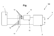
- the figure shows schematically a section of the generator apparatus 100 according to the invention as a circuit diagram.
- the generator apparatus according to the figure comprises a motor 1, which is preferably configured as a Stirling engine or the like.
- the motor comprises at least one alternating working piston which produces mechanical energy in the form of a movement during corresponding operation, for example, during combustion of a fuel.
- Coupled to the motor 1 is a generator not shown here which converts the mechanical energy into electrical energy.
- the generator is designed for an optimal operating point, for example, for a voltage of 230 V.
- a regulating device 2 configured as a motor control and voltage network connection is provided for generating electrical energy via the generator.
- the motor is driven via the motor control so that this generates energy.
- the generated energy is fed into a voltage network 3.
- a converter device 10 is connected between motor 1 and motor control 2 so that the generated energy is not coupled directly into the voltage network 3. If other mains parameters are available, as for example, elsewhere in Europe, an adaptation to the changed relationships is provided by means of the converter device 10 so that the motor 1 continues to operate at the optimal operating point.
- the converter device 10 comprises, inter alia, a coil 11 with a plurality of windings 12.
- a plurality of connection points 13 to the windings is provided which can be coupled to the generator and/or the regulating device 2 selectively by means of a switch 15.
- Various voltage relationships can be set by means of this plurality of connection points 13 which can each be adapted to the applied voltage network 3.
- the switching can take place manually or automatically, wherein in the case of automatic switching, detection is provided to identify relationships deviating from an optimal operating point.
- the switch 15 shown is configured as an incremental switch in order to effect an incremental switching.
- the generator apparatus 100 shown in the figure can preferably be used in combined heat and power systems and here in particular in so-called micro-combined heat and power systems.
- such systems can be designed to be small without any loss of power taking place.
- micro-combined heat and power systems are used in many different countries having different voltage networks.
- an automatic adaptation to different voltage should be provided for ease of operation.
- the performance of micro-combined heat and power appliances can be sensitive to variations in network voltage and operating power. As such an automatic adaptation to different voltage or power should be provided to optimise performance of the unit in relation to efficiency and power output.
Landscapes
- Engineering & Computer Science (AREA)
- Power Engineering (AREA)
- Chemical & Material Sciences (AREA)
- Combustion & Propulsion (AREA)
- Mechanical Engineering (AREA)
- General Engineering & Computer Science (AREA)
- Control Of Eletrric Generators (AREA)
Applications Claiming Priority (1)
| Application Number | Priority Date | Filing Date | Title |
|---|---|---|---|
| GB1004935A GB2478947A (en) | 2010-03-24 | 2010-03-24 | Combined heat and power system with efficient operating mode |
Publications (2)
| Publication Number | Publication Date |
|---|---|
| EP2372897A2 true EP2372897A2 (de) | 2011-10-05 |
| EP2372897A3 EP2372897A3 (de) | 2014-05-14 |
Family
ID=42228259
Family Applications (1)
| Application Number | Title | Priority Date | Filing Date |
|---|---|---|---|
| EP11159187.1A Withdrawn EP2372897A3 (de) | 2010-03-24 | 2011-03-22 | Generatorvorrichtung für ein kombiniertes Wärme- und Stromsystem, Verfahren zur Bedienung der Generatorvorrichtung und kombiniertes Wärme- und Stromsystem |
Country Status (2)
| Country | Link |
|---|---|
| EP (1) | EP2372897A3 (de) |
| GB (1) | GB2478947A (de) |
Family Cites Families (3)
| Publication number | Priority date | Publication date | Assignee | Title |
|---|---|---|---|---|
| JP5005271B2 (ja) * | 2006-06-23 | 2012-08-22 | アイシン精機株式会社 | 電源装置 |
| EP2014880A1 (de) * | 2007-07-09 | 2009-01-14 | Universiteit Gent | Verbessertes kombiniertes Wärme- und Stromsystem |
| WO2009073841A1 (en) * | 2007-12-05 | 2009-06-11 | Sunpower, Inc. | Hybrid electrical power source |
-
2010
- 2010-03-24 GB GB1004935A patent/GB2478947A/en not_active Withdrawn
-
2011
- 2011-03-22 EP EP11159187.1A patent/EP2372897A3/de not_active Withdrawn
Non-Patent Citations (1)
| Title |
|---|
| None |
Also Published As
| Publication number | Publication date |
|---|---|
| EP2372897A3 (de) | 2014-05-14 |
| GB2478947A (en) | 2011-09-28 |
| GB201004935D0 (en) | 2010-05-12 |
Similar Documents
| Publication | Publication Date | Title |
|---|---|---|
| US7190085B2 (en) | Wind turbine for producing electrical power and a method of operating the same | |
| KR100612816B1 (ko) | 풍력장치 작동 방법 및 풍력장치 | |
| US9541067B2 (en) | Method for operating a wind turbine or a wind farm | |
| CN106208071B (zh) | 混合式ac及dc分配系统和使用方法 | |
| US9024557B2 (en) | Variable switching frequency power converter | |
| RU2014141647A (ru) | Способ управления устройством для ввода электрического тока в сеть электроснабжения | |
| GB2458807A (en) | Starting variable speed generators | |
| US7038329B1 (en) | Quality power from induction generator feeding variable speed motors | |
| JP2015509698A (ja) | 電気ユニットの使用方法 | |
| EP2372897A2 (de) | Generatorvorrichtung für ein kombiniertes Wärme- und Stromsystem, Verfahren zur Bedienung der Generatorvorrichtung und kombiniertes Wärme- und Stromsystem | |
| RU2724104C1 (ru) | Автономная двухагрегатная электростанция | |
| KR101019676B1 (ko) | 서보모터를 이용한 저소음 발전시스템 | |
| KR102800740B1 (ko) | 블로어 및 유압기에 적용되는 전동기의 스마트 제어 장치 | |
| RU158933U1 (ru) | Автономная ветро-дизель-электрическая установка | |
| AU2022287680B2 (en) | Hybrid generator | |
| CN204174655U (zh) | 电动液压挖掘机交流变频调速控制系统 | |
| RU103259U1 (ru) | Электроэнергетическая установка | |
| EP2416489B1 (de) | System zum Erzeugen von Strom und Verfahren zum Betreiben des Systems | |
| RU2588001C1 (ru) | Автономная мультимодульная установка генерирования электрической энергии ограниченной мощности | |
| RU2460203C1 (ru) | Электроэнергетическая установка | |
| EP2106010B1 (de) | Kraftwerk und Verfahren zur Steuerung des Kraftwerkes | |
| KR101068893B1 (ko) | 고효율 발전 시스템 | |
| JP2015111962A (ja) | 並列運転電源システム | |
| CN114244200A (zh) | 一种大功率通用型整流装置及其控制方法 | |
| JP2015037363A (ja) | 電力変換装置 |
Legal Events
| Date | Code | Title | Description |
|---|---|---|---|
| PUAI | Public reference made under article 153(3) epc to a published international application that has entered the european phase |
Free format text: ORIGINAL CODE: 0009012 |
|
| AK | Designated contracting states |
Kind code of ref document: A2 Designated state(s): AL AT BE BG CH CY CZ DE DK EE ES FI FR GB GR HR HU IE IS IT LI LT LU LV MC MK MT NL NO PL PT RO RS SE SI SK SM TR |
|
| AX | Request for extension of the european patent |
Extension state: BA ME |
|
| PUAL | Search report despatched |
Free format text: ORIGINAL CODE: 0009013 |
|
| AK | Designated contracting states |
Kind code of ref document: A3 Designated state(s): AL AT BE BG CH CY CZ DE DK EE ES FI FR GB GR HR HU IE IS IT LI LT LU LV MC MK MT NL NO PL PT RO RS SE SI SK SM TR |
|
| AX | Request for extension of the european patent |
Extension state: BA ME |
|
| RIC1 | Information provided on ipc code assigned before grant |
Ipc: H02P 4/00 20060101AFI20140408BHEP Ipc: H02P 9/04 20060101ALN20140408BHEP Ipc: H02P 9/10 20060101ALI20140408BHEP Ipc: H02P 9/30 20060101ALI20140408BHEP |
|
| STAA | Information on the status of an ep patent application or granted ep patent |
Free format text: STATUS: THE APPLICATION IS DEEMED TO BE WITHDRAWN |
|
| 18D | Application deemed to be withdrawn |
Effective date: 20141115 |