EP2372880A2 - Démarreur-générateur à profil bas - Google Patents
Démarreur-générateur à profil bas Download PDFInfo
- Publication number
- EP2372880A2 EP2372880A2 EP11156502A EP11156502A EP2372880A2 EP 2372880 A2 EP2372880 A2 EP 2372880A2 EP 11156502 A EP11156502 A EP 11156502A EP 11156502 A EP11156502 A EP 11156502A EP 2372880 A2 EP2372880 A2 EP 2372880A2
- Authority
- EP
- European Patent Office
- Prior art keywords
- electric machine
- shaft
- exciter
- generator
- axis
- Prior art date
- Legal status (The legal status is an assumption and is not a legal conclusion. Google has not performed a legal analysis and makes no representation as to the accuracy of the status listed.)
- Withdrawn
Links
Images


Classifications
-
- H—ELECTRICITY
- H02—GENERATION; CONVERSION OR DISTRIBUTION OF ELECTRIC POWER
- H02K—DYNAMO-ELECTRIC MACHINES
- H02K7/00—Arrangements for handling mechanical energy structurally associated with dynamo-electric machines, e.g. structural association with mechanical driving motors or auxiliary dynamo-electric machines
- H02K7/006—Structural association of a motor or generator with the drive train of a motor vehicle
-
- B—PERFORMING OPERATIONS; TRANSPORTING
- B60—VEHICLES IN GENERAL
- B60K—ARRANGEMENT OR MOUNTING OF PROPULSION UNITS OR OF TRANSMISSIONS IN VEHICLES; ARRANGEMENT OR MOUNTING OF PLURAL DIVERSE PRIME-MOVERS IN VEHICLES; AUXILIARY DRIVES FOR VEHICLES; INSTRUMENTATION OR DASHBOARDS FOR VEHICLES; ARRANGEMENTS IN CONNECTION WITH COOLING, AIR INTAKE, GAS EXHAUST OR FUEL SUPPLY OF PROPULSION UNITS IN VEHICLES
- B60K6/00—Arrangement or mounting of plural diverse prime-movers for mutual or common propulsion, e.g. hybrid propulsion systems comprising electric motors and internal combustion engines ; Control systems therefor, i.e. systems controlling two or more prime movers, or controlling one of these prime movers and any of the transmission, drive or drive units Informative references: mechanical gearings with secondary electric drive F16H3/72; arrangements for handling mechanical energy structurally associated with the dynamo-electric machine H02K7/00; machines comprising structurally interrelated motor and generator parts H02K51/00; dynamo-electric machines not otherwise provided for in H02K see H02K99/00
- B60K6/20—Arrangement or mounting of plural diverse prime-movers for mutual or common propulsion, e.g. hybrid propulsion systems comprising electric motors and internal combustion engines ; Control systems therefor, i.e. systems controlling two or more prime movers, or controlling one of these prime movers and any of the transmission, drive or drive units Informative references: mechanical gearings with secondary electric drive F16H3/72; arrangements for handling mechanical energy structurally associated with the dynamo-electric machine H02K7/00; machines comprising structurally interrelated motor and generator parts H02K51/00; dynamo-electric machines not otherwise provided for in H02K see H02K99/00 the prime-movers consisting of electric motors and internal combustion engines, e.g. HEVs
- B60K6/42—Arrangement or mounting of plural diverse prime-movers for mutual or common propulsion, e.g. hybrid propulsion systems comprising electric motors and internal combustion engines ; Control systems therefor, i.e. systems controlling two or more prime movers, or controlling one of these prime movers and any of the transmission, drive or drive units Informative references: mechanical gearings with secondary electric drive F16H3/72; arrangements for handling mechanical energy structurally associated with the dynamo-electric machine H02K7/00; machines comprising structurally interrelated motor and generator parts H02K51/00; dynamo-electric machines not otherwise provided for in H02K see H02K99/00 the prime-movers consisting of electric motors and internal combustion engines, e.g. HEVs characterised by the architecture of the hybrid electric vehicle
- B60K6/48—Parallel type
-
- B—PERFORMING OPERATIONS; TRANSPORTING
- B60—VEHICLES IN GENERAL
- B60L—PROPULSION OF ELECTRICALLY-PROPELLED VEHICLES; SUPPLYING ELECTRIC POWER FOR AUXILIARY EQUIPMENT OF ELECTRICALLY-PROPELLED VEHICLES; ELECTRODYNAMIC BRAKE SYSTEMS FOR VEHICLES IN GENERAL; MAGNETIC SUSPENSION OR LEVITATION FOR VEHICLES; MONITORING OPERATING VARIABLES OF ELECTRICALLY-PROPELLED VEHICLES; ELECTRIC SAFETY DEVICES FOR ELECTRICALLY-PROPELLED VEHICLES
- B60L1/00—Supplying electric power to auxiliary equipment of vehicles
- B60L1/02—Supplying electric power to auxiliary equipment of vehicles to electric heating circuits
-
- B—PERFORMING OPERATIONS; TRANSPORTING
- B60—VEHICLES IN GENERAL
- B60L—PROPULSION OF ELECTRICALLY-PROPELLED VEHICLES; SUPPLYING ELECTRIC POWER FOR AUXILIARY EQUIPMENT OF ELECTRICALLY-PROPELLED VEHICLES; ELECTRODYNAMIC BRAKE SYSTEMS FOR VEHICLES IN GENERAL; MAGNETIC SUSPENSION OR LEVITATION FOR VEHICLES; MONITORING OPERATING VARIABLES OF ELECTRICALLY-PROPELLED VEHICLES; ELECTRIC SAFETY DEVICES FOR ELECTRICALLY-PROPELLED VEHICLES
- B60L3/00—Electric devices on electrically-propelled vehicles for safety purposes; Monitoring operating variables, e.g. speed, deceleration or energy consumption
- B60L3/0023—Detecting, eliminating, remedying or compensating for drive train abnormalities, e.g. failures within the drive train
- B60L3/0061—Detecting, eliminating, remedying or compensating for drive train abnormalities, e.g. failures within the drive train relating to electrical machines
-
- B—PERFORMING OPERATIONS; TRANSPORTING
- B60—VEHICLES IN GENERAL
- B60L—PROPULSION OF ELECTRICALLY-PROPELLED VEHICLES; SUPPLYING ELECTRIC POWER FOR AUXILIARY EQUIPMENT OF ELECTRICALLY-PROPELLED VEHICLES; ELECTRODYNAMIC BRAKE SYSTEMS FOR VEHICLES IN GENERAL; MAGNETIC SUSPENSION OR LEVITATION FOR VEHICLES; MONITORING OPERATING VARIABLES OF ELECTRICALLY-PROPELLED VEHICLES; ELECTRIC SAFETY DEVICES FOR ELECTRICALLY-PROPELLED VEHICLES
- B60L50/00—Electric propulsion with power supplied within the vehicle
- B60L50/10—Electric propulsion with power supplied within the vehicle using propulsion power supplied by engine-driven generators, e.g. generators driven by combustion engines
- B60L50/16—Electric propulsion with power supplied within the vehicle using propulsion power supplied by engine-driven generators, e.g. generators driven by combustion engines with provision for separate direct mechanical propulsion
-
- H—ELECTRICITY
- H02—GENERATION; CONVERSION OR DISTRIBUTION OF ELECTRIC POWER
- H02K—DYNAMO-ELECTRIC MACHINES
- H02K19/00—Synchronous motors or generators
- H02K19/16—Synchronous generators
- H02K19/26—Synchronous generators characterised by the arrangement of exciting windings
- H02K19/28—Synchronous generators characterised by the arrangement of exciting windings for self-excitation
-
- H—ELECTRICITY
- H02—GENERATION; CONVERSION OR DISTRIBUTION OF ELECTRIC POWER
- H02K—DYNAMO-ELECTRIC MACHINES
- H02K19/00—Synchronous motors or generators
- H02K19/16—Synchronous generators
- H02K19/38—Structural association of synchronous generators with exciting machines
-
- B—PERFORMING OPERATIONS; TRANSPORTING
- B60—VEHICLES IN GENERAL
- B60K—ARRANGEMENT OR MOUNTING OF PROPULSION UNITS OR OF TRANSMISSIONS IN VEHICLES; ARRANGEMENT OR MOUNTING OF PLURAL DIVERSE PRIME-MOVERS IN VEHICLES; AUXILIARY DRIVES FOR VEHICLES; INSTRUMENTATION OR DASHBOARDS FOR VEHICLES; ARRANGEMENTS IN CONNECTION WITH COOLING, AIR INTAKE, GAS EXHAUST OR FUEL SUPPLY OF PROPULSION UNITS IN VEHICLES
- B60K6/00—Arrangement or mounting of plural diverse prime-movers for mutual or common propulsion, e.g. hybrid propulsion systems comprising electric motors and internal combustion engines ; Control systems therefor, i.e. systems controlling two or more prime movers, or controlling one of these prime movers and any of the transmission, drive or drive units Informative references: mechanical gearings with secondary electric drive F16H3/72; arrangements for handling mechanical energy structurally associated with the dynamo-electric machine H02K7/00; machines comprising structurally interrelated motor and generator parts H02K51/00; dynamo-electric machines not otherwise provided for in H02K see H02K99/00
- B60K6/20—Arrangement or mounting of plural diverse prime-movers for mutual or common propulsion, e.g. hybrid propulsion systems comprising electric motors and internal combustion engines ; Control systems therefor, i.e. systems controlling two or more prime movers, or controlling one of these prime movers and any of the transmission, drive or drive units Informative references: mechanical gearings with secondary electric drive F16H3/72; arrangements for handling mechanical energy structurally associated with the dynamo-electric machine H02K7/00; machines comprising structurally interrelated motor and generator parts H02K51/00; dynamo-electric machines not otherwise provided for in H02K see H02K99/00 the prime-movers consisting of electric motors and internal combustion engines, e.g. HEVs
- B60K6/42—Arrangement or mounting of plural diverse prime-movers for mutual or common propulsion, e.g. hybrid propulsion systems comprising electric motors and internal combustion engines ; Control systems therefor, i.e. systems controlling two or more prime movers, or controlling one of these prime movers and any of the transmission, drive or drive units Informative references: mechanical gearings with secondary electric drive F16H3/72; arrangements for handling mechanical energy structurally associated with the dynamo-electric machine H02K7/00; machines comprising structurally interrelated motor and generator parts H02K51/00; dynamo-electric machines not otherwise provided for in H02K see H02K99/00 the prime-movers consisting of electric motors and internal combustion engines, e.g. HEVs characterised by the architecture of the hybrid electric vehicle
- B60K6/48—Parallel type
- B60K2006/4816—Electric machine connected or connectable to gearbox internal shaft
-
- B—PERFORMING OPERATIONS; TRANSPORTING
- B60—VEHICLES IN GENERAL
- B60K—ARRANGEMENT OR MOUNTING OF PROPULSION UNITS OR OF TRANSMISSIONS IN VEHICLES; ARRANGEMENT OR MOUNTING OF PLURAL DIVERSE PRIME-MOVERS IN VEHICLES; AUXILIARY DRIVES FOR VEHICLES; INSTRUMENTATION OR DASHBOARDS FOR VEHICLES; ARRANGEMENTS IN CONNECTION WITH COOLING, AIR INTAKE, GAS EXHAUST OR FUEL SUPPLY OF PROPULSION UNITS IN VEHICLES
- B60K6/00—Arrangement or mounting of plural diverse prime-movers for mutual or common propulsion, e.g. hybrid propulsion systems comprising electric motors and internal combustion engines ; Control systems therefor, i.e. systems controlling two or more prime movers, or controlling one of these prime movers and any of the transmission, drive or drive units Informative references: mechanical gearings with secondary electric drive F16H3/72; arrangements for handling mechanical energy structurally associated with the dynamo-electric machine H02K7/00; machines comprising structurally interrelated motor and generator parts H02K51/00; dynamo-electric machines not otherwise provided for in H02K see H02K99/00
- B60K6/20—Arrangement or mounting of plural diverse prime-movers for mutual or common propulsion, e.g. hybrid propulsion systems comprising electric motors and internal combustion engines ; Control systems therefor, i.e. systems controlling two or more prime movers, or controlling one of these prime movers and any of the transmission, drive or drive units Informative references: mechanical gearings with secondary electric drive F16H3/72; arrangements for handling mechanical energy structurally associated with the dynamo-electric machine H02K7/00; machines comprising structurally interrelated motor and generator parts H02K51/00; dynamo-electric machines not otherwise provided for in H02K see H02K99/00 the prime-movers consisting of electric motors and internal combustion engines, e.g. HEVs
- B60K6/42—Arrangement or mounting of plural diverse prime-movers for mutual or common propulsion, e.g. hybrid propulsion systems comprising electric motors and internal combustion engines ; Control systems therefor, i.e. systems controlling two or more prime movers, or controlling one of these prime movers and any of the transmission, drive or drive units Informative references: mechanical gearings with secondary electric drive F16H3/72; arrangements for handling mechanical energy structurally associated with the dynamo-electric machine H02K7/00; machines comprising structurally interrelated motor and generator parts H02K51/00; dynamo-electric machines not otherwise provided for in H02K see H02K99/00 the prime-movers consisting of electric motors and internal combustion engines, e.g. HEVs characterised by the architecture of the hybrid electric vehicle
- B60K6/48—Parallel type
- B60K2006/4825—Electric machine connected or connectable to gearbox input shaft
-
- B—PERFORMING OPERATIONS; TRANSPORTING
- B60—VEHICLES IN GENERAL
- B60K—ARRANGEMENT OR MOUNTING OF PROPULSION UNITS OR OF TRANSMISSIONS IN VEHICLES; ARRANGEMENT OR MOUNTING OF PLURAL DIVERSE PRIME-MOVERS IN VEHICLES; AUXILIARY DRIVES FOR VEHICLES; INSTRUMENTATION OR DASHBOARDS FOR VEHICLES; ARRANGEMENTS IN CONNECTION WITH COOLING, AIR INTAKE, GAS EXHAUST OR FUEL SUPPLY OF PROPULSION UNITS IN VEHICLES
- B60K6/00—Arrangement or mounting of plural diverse prime-movers for mutual or common propulsion, e.g. hybrid propulsion systems comprising electric motors and internal combustion engines ; Control systems therefor, i.e. systems controlling two or more prime movers, or controlling one of these prime movers and any of the transmission, drive or drive units Informative references: mechanical gearings with secondary electric drive F16H3/72; arrangements for handling mechanical energy structurally associated with the dynamo-electric machine H02K7/00; machines comprising structurally interrelated motor and generator parts H02K51/00; dynamo-electric machines not otherwise provided for in H02K see H02K99/00
- B60K6/20—Arrangement or mounting of plural diverse prime-movers for mutual or common propulsion, e.g. hybrid propulsion systems comprising electric motors and internal combustion engines ; Control systems therefor, i.e. systems controlling two or more prime movers, or controlling one of these prime movers and any of the transmission, drive or drive units Informative references: mechanical gearings with secondary electric drive F16H3/72; arrangements for handling mechanical energy structurally associated with the dynamo-electric machine H02K7/00; machines comprising structurally interrelated motor and generator parts H02K51/00; dynamo-electric machines not otherwise provided for in H02K see H02K99/00 the prime-movers consisting of electric motors and internal combustion engines, e.g. HEVs
- B60K6/42—Arrangement or mounting of plural diverse prime-movers for mutual or common propulsion, e.g. hybrid propulsion systems comprising electric motors and internal combustion engines ; Control systems therefor, i.e. systems controlling two or more prime movers, or controlling one of these prime movers and any of the transmission, drive or drive units Informative references: mechanical gearings with secondary electric drive F16H3/72; arrangements for handling mechanical energy structurally associated with the dynamo-electric machine H02K7/00; machines comprising structurally interrelated motor and generator parts H02K51/00; dynamo-electric machines not otherwise provided for in H02K see H02K99/00 the prime-movers consisting of electric motors and internal combustion engines, e.g. HEVs characterised by the architecture of the hybrid electric vehicle
- B60K6/48—Parallel type
- B60K6/485—Motor-assist type
-
- B—PERFORMING OPERATIONS; TRANSPORTING
- B60—VEHICLES IN GENERAL
- B60L—PROPULSION OF ELECTRICALLY-PROPELLED VEHICLES; SUPPLYING ELECTRIC POWER FOR AUXILIARY EQUIPMENT OF ELECTRICALLY-PROPELLED VEHICLES; ELECTRODYNAMIC BRAKE SYSTEMS FOR VEHICLES IN GENERAL; MAGNETIC SUSPENSION OR LEVITATION FOR VEHICLES; MONITORING OPERATING VARIABLES OF ELECTRICALLY-PROPELLED VEHICLES; ELECTRIC SAFETY DEVICES FOR ELECTRICALLY-PROPELLED VEHICLES
- B60L2240/00—Control parameters of input or output; Target parameters
- B60L2240/10—Vehicle control parameters
- B60L2240/36—Temperature of vehicle components or parts
-
- Y—GENERAL TAGGING OF NEW TECHNOLOGICAL DEVELOPMENTS; GENERAL TAGGING OF CROSS-SECTIONAL TECHNOLOGIES SPANNING OVER SEVERAL SECTIONS OF THE IPC; TECHNICAL SUBJECTS COVERED BY FORMER USPC CROSS-REFERENCE ART COLLECTIONS [XRACs] AND DIGESTS
- Y02—TECHNOLOGIES OR APPLICATIONS FOR MITIGATION OR ADAPTATION AGAINST CLIMATE CHANGE
- Y02T—CLIMATE CHANGE MITIGATION TECHNOLOGIES RELATED TO TRANSPORTATION
- Y02T10/00—Road transport of goods or passengers
- Y02T10/60—Other road transportation technologies with climate change mitigation effect
- Y02T10/62—Hybrid vehicles
-
- Y—GENERAL TAGGING OF NEW TECHNOLOGICAL DEVELOPMENTS; GENERAL TAGGING OF CROSS-SECTIONAL TECHNOLOGIES SPANNING OVER SEVERAL SECTIONS OF THE IPC; TECHNICAL SUBJECTS COVERED BY FORMER USPC CROSS-REFERENCE ART COLLECTIONS [XRACs] AND DIGESTS
- Y02—TECHNOLOGIES OR APPLICATIONS FOR MITIGATION OR ADAPTATION AGAINST CLIMATE CHANGE
- Y02T—CLIMATE CHANGE MITIGATION TECHNOLOGIES RELATED TO TRANSPORTATION
- Y02T10/00—Road transport of goods or passengers
- Y02T10/60—Other road transportation technologies with climate change mitigation effect
- Y02T10/64—Electric machine technologies in electromobility
-
- Y—GENERAL TAGGING OF NEW TECHNOLOGICAL DEVELOPMENTS; GENERAL TAGGING OF CROSS-SECTIONAL TECHNOLOGIES SPANNING OVER SEVERAL SECTIONS OF THE IPC; TECHNICAL SUBJECTS COVERED BY FORMER USPC CROSS-REFERENCE ART COLLECTIONS [XRACs] AND DIGESTS
- Y02—TECHNOLOGIES OR APPLICATIONS FOR MITIGATION OR ADAPTATION AGAINST CLIMATE CHANGE
- Y02T—CLIMATE CHANGE MITIGATION TECHNOLOGIES RELATED TO TRANSPORTATION
- Y02T10/00—Road transport of goods or passengers
- Y02T10/60—Other road transportation technologies with climate change mitigation effect
- Y02T10/70—Energy storage systems for electromobility, e.g. batteries
-
- Y—GENERAL TAGGING OF NEW TECHNOLOGICAL DEVELOPMENTS; GENERAL TAGGING OF CROSS-SECTIONAL TECHNOLOGIES SPANNING OVER SEVERAL SECTIONS OF THE IPC; TECHNICAL SUBJECTS COVERED BY FORMER USPC CROSS-REFERENCE ART COLLECTIONS [XRACs] AND DIGESTS
- Y02—TECHNOLOGIES OR APPLICATIONS FOR MITIGATION OR ADAPTATION AGAINST CLIMATE CHANGE
- Y02T—CLIMATE CHANGE MITIGATION TECHNOLOGIES RELATED TO TRANSPORTATION
- Y02T10/00—Road transport of goods or passengers
- Y02T10/60—Other road transportation technologies with climate change mitigation effect
- Y02T10/7072—Electromobility specific charging systems or methods for batteries, ultracapacitors, supercapacitors or double-layer capacitors
Definitions
- the present invention generally relates to electrical power in a vehicle. More particularly, the present invention relates to vehicular electric machines (starters, generators and starter-generators).
- an electric machine directly between an output shaft of an engine and a transmission of the vehicle.
- This may be a particularly desirable arrangement when the vehicle has on-board electrical loads which require large amounts of power and the electric machine may have a large electrical output capacity.
- the electric machine may be positioned so that it consumes minimal space in an engine/transmission envelope.
- the electric machine may be positioned coaxially with a drive shaft of the engine and may not need to be placed alongside the engine.
- coaxially positioned electric machines are constructed as permanent magnet (PM) electric machines.
- PM electric machines may produce power with a voltage that varies as a function of their rotational speed and the electrical load. When such machines are driven by a variable speed engine, their output must be conditioned prior to being delivered to electrical loads.
- wound field starter-generators may produce output power that may be controlled to a fixed voltage even though rotational speed of, and/or the electrical load on, the wound field machine may vary.
- Wound field machines may have advantages in vehicular applications because they may output power that may not require use of power conditioning equipment. Thus overall weight and cost of a wound-field based electrical system may be lower than that of a PM-based electrical system because there may be no need for on-board power conditioning equipment.
- PM systems have heretofore been employed in applications that require a coaxial arrangement of a starter-generator with its respective engine output shaft.
- a typical PM machine may be constructed with a smaller axial length than a typical wound field machine.
- a typical wound field machine may consist of an exciter generator and a main generator. Thus two generators may consume side-by-side space in many wound-field machine designs.
- Some newly developed wound field machines have their exciter generators and their main generators concentrically arranged in a so-called "low profile" configuration. Such a machine is described in US Patent 7,230,363 , which is incorporated by reference herein.
- While the concentrically arranged wound-field machine of US Patent 7,230,363 may have a desirably small envelope, it nevertheless is not configured for positioning between an engine and a transmission coaxially with an output shaft of an engine. This is because the machine of US Patent 7,230,363 does not have a through-shaft configuration for transferring mechanical power to the vehicle transmission.
- a power system for a vehicle may comprise an electric machine interposed between an engine and a transmission of the vehicle; the electric machine comprising; an exciter generator with exciter armature windings surrounding an axis; a main generator with main field windings surrounding the axis so that the exciter generator and the main generator are concentric; a rotor coaxial with the axis and the rotor supporting the exciter armature windings and the main field windings; wherein the rotor has a first end attached to the engine power output shaft and a second end adapted to deliver mechanical power from the engine to the transmission.
- an electric machine for a vehicle may comprise a housing and a rotor assembly.
- the rotor assembly may comprise an exciter armature winding; a main generator field winding; and a shaft for supporting the exciter armature winding and the main generator field winding concentrically with an axis of the shaft.
- the shaft may have a first end accessible at a first end of the housing and a second end accessible at a second end of the housing, so that mechanical power can be transmitted through the electric machine.
- a method for operating a vehicle may comprise the steps of rotating a rotor of an electric machine with a power output shaft of an engine of the vehicle; rotating a transmission of the vehicle with the rotor of the electric machine; generating electrical excitation with the rotation of the rotor, and generating electrical power with the rotor and with the excitation.
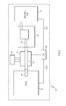
- FIG. 1 is a block diagram of a power system in accordance with an embodiment of the invention.
- Figure 2 is a partial cross-sectional elevation view of a first configuration of an electric machine in accordance with an embodiment of the invention
- Figure 3 is a partial cross-sectional elevation view of a second configuration of an electric machine in accordance with an embodiment of the invention.
- Figure 4 is a flow chart of for operating an electrical power system in accordance with an embodiment of the invention.
- embodiments of the present invention generally provide a vehicular electrical system in which a through-shaft wound field electric machine may be positioned between an engine output shaft and a transmission of a vehicle so that the electric machine may be directly driven by the engine and so that the engine may directly deliver mechanical power to the transmission.
- the through-shaft wound field electric machine may advantageously have a low profile configuration.
- a power system 10 for a vehicle may comprise an engine 12, an electric machine 14, a transmission 16, electrical loads 18 and mechanical loads 20.
- the electric machine 14 may be a wound-field generator or starter/generator.
- the electric machine 14 may have a shaft 22 which may be aligned coaxially with an engine power output shaft 24.
- the transmission 16 may have a power input shaft 26 which may be aligned coaxially with the shaft 22.
- the transmission 16 may be positioned to deliver mechanical power to the mechanical loads 20.
- the electric machine 14 may be connected to deliver electrical power to the electrical loads 18.
- a generator control unit (GCU) 30 may receive signals 30-1 that may be indicative of the generator output voltage.
- the GCU 30 may control excitation levels in the electric machine 14 so that the electric machine 14 may produce electrical power with a desired voltage, irrespective of rotational speed of the engine 12, or the magnitude of electrical load.
- the electric machine may comprise an exciter generator 14-2 concentrically positioned with a main generator 14-4. More specifically, the electric machine 14 may comprise a housing 40 a rotor assembly 42, a main stator 44 and an exciter stator 46.
- the rotor assembly 42 may comprise an exciter armature winding 42-2, a main field winding 42-4 and the electric machine shaft 22.
- the shaft 22 may support the exciter armature winding 42-2 and the main field winding 42-4 concentrically with an axis 22-2 of the shaft 22.
- the shaft 22 may be a through shaft and may have a first end 22-4 accessible at a first end 40-2 of the housing 40 and a second end 22-6 accessible at a second end 40-4 of the housing (housing) 40, so that mechanical power may be transmitted through the electric machine 14.
- the shaft 22 may be connected to an intermediate electricmachine output shaft (not shown) which intermediate shaft may be connected to the transmission 16.
- the electric machine 14 may be considered to have its rotor assembly 42 adapted to deliver mechanical power to the transmission 16.
- the exciter stator 46 may be positioned concentrically with the axis 22-2 and concentrically with the exciter armature winding 42-2 and the main field winding 42-4.
- the main stator 44 may be positioned concentrically with the axis 22-2 and may surround the main field winding 42-4.
- the electric machine shaft 22 may comprise a central member 22-8 and an annular member 22-10 surrounding the central member 22-8 and attached to the central member 22-8.
- a cylindrical member 22-12 of the shaft 22 may be attached to the annular 22-10 member concentrically with the axis 22-2 of shaft 22 of the electric machine 14.
- the exciter armature winding 42-2 may be supported on an inner side 22-12-2 of the cylindrical member 22-12.
- the main field winding 42-4 may be supported on an outer side 22-12-4 of the cylindrical member 22-12.
- the exciter armature winding 42-2 may be configured so that it delivers three-phase AC power to rectifying diodes 23 so that DC excitation current may be supplied to the main field windings 42-4.
- the diodes 23 may be attached to the inner side 22-12-2 of the cylindrical member 22-12 in a full-bridge configuration.
- the term “inner side” may refer to those objects which are radially closer to an axis such as the axis 22-2. Conversely, the term “outer side” may refer to those objects which are radially further from an axis such as the axis 22-2.
- the electric machine 14 may also comprise a first bearing 50 and a second bearing 52 which may facilitate relative rotational motion between the shaft 22 and the housing 40.
- the annular member 22-10 of the shaft 22 may be interposed axially between the first and the second bearing 50 and 52.
- the bearings 50 and 52 may be sealed bearings.
- the housing 40 may comprise an outer cylindrical housing shell 40-1 and an inner cylindrical housing shell 40-3
- the housing end 40-2 may attached to the outer cylindrical housing shell 40-1 and the inner cylindrical housing shell 40-3.
- the housing end 40-4 may be attached to the outer cylindrical housing shell 40-1.
- the bearing 50 may be interposed radially between the inner cylindrical housing shell 40-3 and the shaft 22.
- the bearing 52 may be interposed radially between the housing end 40-4 and the shaft 22
- an electric machine 15 may comprise an exciter generator 15-2 concentrically positioned with a main generator 15-4. More specifically, the electric machine 15 may comprise a housing (housing) 140, a rotor assembly 142, a main stator 144 and an exciter stator 146.
- the rotor assembly 142 may comprise an exciter armature winding 142-2, a main field winding 142-4 and an electric machine shaft 122 which may support the exciter armature winding 142-2 and the main field winding 142-4 concentrically with an axis 122-2 of the shaft 122.
- the shaft 122 may have a first end 122-4 accessible at a first end 140-2 of the housing 140 and a second end 122-6 accessible at a second end 140-4 of the housing (housing) 140, so that mechanical power may be transmitted through the electric machine 15.
- the exciter stator 146 may be positioned concentrically with the axis 122-2 and concentrically with the exciter armature winding 142-2 and the main field winding 142-4.
- the main stator 144 may be positioned concentrically with the axis 122-2 and may surround the main field winding 142-4.
- the electric machine shaft 122 may comprise a central member 122-8, an annular member 122-10 surrounding the central member 122-8 and attached to the central member 122-8.
- a cylindrical member 122-12 of the shaft 122 may be attached to the annular 122-10 member concentrically with the axis 122-2 the shaft 122 of the electric machine 15.
- the exciter armature winding 142-2 may be supported on an inner side 122-12-2 of the cylindrical member 122-12.
- the main field winding 142-4 may be supported on an outer side 122-12-4 of the cylindrical member 122-12.
- the housing 140 may comprise an outer cylindrical housing shell 140-8 with an inner side 140-8-2 and an outer side 140-8-4; an inner cylindrical housing shell 140-10 with an inner side 140-10-2 and an outer side 140-10-4; and an intermediate cylindrical housing shell 140-12 having an inner side 140-12-2 and an outer side 140-12-4.
- the cylindrical housing shells 140-8, 140-10 and 140-12 may be positioned concentrically with the axis 122-2 of the shaft 122.
- the intermediate cylindrical housing shell 140-12 may be interposed radially between the outer cylindrical housing shell 140-8 and the inner cylindrical housing shell 140-10.
- the main stator winding 144 may be attached to the inner side 140-8-2 of the outer cylindrical housing shell 140-8.
- the exciter stator winding 146 may be attached to the outer side 140-10-4 of the inner cylindrical housing shell 140-10.
- a first bearing 150 may be radially interposed between the central member 122-8 of the shaft 122 and the end 140-4 of the housing 140.
- a second bearing 152 may be radially interposed between the inner side 122-12-2 of the cylindrical member 122-12 of the shaft 122 and the outer side 140-12-4 of the intermediate cylindrical housing shell 140-12 of the housing 140.
- a seal 154 may be positioned at the end 140-2 of the housing 140 and in engagement with the central member 122-8 of the shaft 122.
- the bearings 150 and 152 may facilitate relative rotational motion between the shaft 122 and the housing 140.
- the annular member 122-10 of the shaft 22 may be interposed axially between the bearings 150 and 152.
- the bearing 150 may be a sealed bearing. Cooling fluid 54 may be sprayed in the electric machine 15 and the sealed bearing 150 and the seal 154 may prevent leakage of the cooling fluid 54 from the electric machine 15
- a flow chart 400 may illustrate an exemplary method which may be employed to operate the power system 10 in accordance with an embodiment the invention.
- an electric machine may be rotated by an engine (e.g., the rotor 42 of the electric machine 14 may be rotated by the drive shaft 24 of the engine 12).
- a transmission of a vehicle may be driven by a shaft of the electric machine (e.g., the shaft 22, which may be integral with the rotor 42 may transmit rotational force from the drive shaft 24 of the engine 12 to the transmission 16).
- the transmission may drive mechanical loads of the vehicle (e.g., the transmission 16 may transmit mechanical power from the engine 12 and the shaft 22 to the mechanical loads 20).
- excitation current may be generated and controlled as a function of generator voltage so that electrical loads on the vehicle are provided with electrical power with constant voltage irrespective of speed of the engine.
- the rotor 42 may rotate the exciter armature windings 42-2 through an electrical field of the exciter stator winding 46 by rotational force imparted by rotation of the shaft 22.
- main electrical power may be produced (e.g., the rotor 42 may rotate the main field windings 42-4 to produce electrical current in the main stator windings 44 by rotational force imparted by rotation of the shaft 22).
- electrical power from step 410 may be used to drive electrical loads (e.g., electrical current from the main stator windings 44 may be transferred to the electrical loads 18).
Landscapes
- Engineering & Computer Science (AREA)
- Power Engineering (AREA)
- Transportation (AREA)
- Mechanical Engineering (AREA)
- Life Sciences & Earth Sciences (AREA)
- Sustainable Development (AREA)
- Sustainable Energy (AREA)
- Chemical & Material Sciences (AREA)
- Combustion & Propulsion (AREA)
- Synchronous Machinery (AREA)
- Connection Of Motors, Electrical Generators, Mechanical Devices, And The Like (AREA)
Applications Claiming Priority (1)
| Application Number | Priority Date | Filing Date | Title |
|---|---|---|---|
| US12/749,810 US20110241465A1 (en) | 2010-03-30 | 2010-03-30 | Low profile starter-generator |
Publications (1)
| Publication Number | Publication Date |
|---|---|
| EP2372880A2 true EP2372880A2 (fr) | 2011-10-05 |
Family
ID=44310323
Family Applications (1)
| Application Number | Title | Priority Date | Filing Date |
|---|---|---|---|
| EP11156502A Withdrawn EP2372880A2 (fr) | 2010-03-30 | 2011-03-01 | Démarreur-générateur à profil bas |
Country Status (2)
| Country | Link |
|---|---|
| US (1) | US20110241465A1 (fr) |
| EP (1) | EP2372880A2 (fr) |
Cited By (4)
| Publication number | Priority date | Publication date | Assignee | Title |
|---|---|---|---|---|
| WO2016188856A1 (fr) * | 2015-05-22 | 2016-12-01 | Continental Automotive Gmbh | Ensemble moteur pour l'entraînement d'un véhicule |
| CN106253620A (zh) * | 2015-06-08 | 2016-12-21 | 科勒公司 | 双轴交流发电机 |
| RU182651U1 (ru) * | 2017-11-29 | 2018-08-24 | Акционерное общество "Шадринский автоагрегатный завод" | Генератор тепловоза |
| CN114665682A (zh) * | 2020-12-22 | 2022-06-24 | 马勒国际有限公司 | 他励电机 |
Families Citing this family (11)
| Publication number | Priority date | Publication date | Assignee | Title |
|---|---|---|---|---|
| JP6191645B2 (ja) * | 2015-03-31 | 2017-09-06 | トヨタ自動車株式会社 | 磁石レス回転電機 |
| US10148207B2 (en) * | 2015-10-16 | 2018-12-04 | Kohler Co. | Segmented waveform converter on controlled field variable speed generator |
| US10778123B2 (en) * | 2015-10-16 | 2020-09-15 | Kohler Co. | Synchronous inverter |
| US10063097B2 (en) * | 2015-10-16 | 2018-08-28 | Kohler Co. | Segmented waveform converter on controlled field variable speed generator |
| US10148202B2 (en) | 2015-10-16 | 2018-12-04 | Kohler Co. | Hybrid device with segmented waveform converter |
| CN105978222A (zh) * | 2016-06-04 | 2016-09-28 | 浙江大学 | 车轴动能回收装置 |
| GB201719053D0 (en) * | 2017-11-17 | 2018-01-03 | Cummins Generator Technologies | Excitation system |
| CA3061496C (fr) * | 2018-11-16 | 2022-10-04 | Enedym Inc. | Machine a reluctance commutee a double stator a simple bobinage |
| US11454172B2 (en) * | 2019-12-26 | 2022-09-27 | Unison Industries, Llc | Starter/generator system |
| DE102021210710A1 (de) | 2021-09-24 | 2023-03-30 | Mahle International Gmbh | Fremderregte elektrische Maschine |
| DE102022124446A1 (de) | 2022-09-23 | 2024-03-28 | Schaeffler Technologies AG & Co. KG | Kontaktlose Energieübertragungsvorrichtung, Kit-of-parts zur Herstellung einer kontaktlosen Energieübertragungsvorrichtung, Rotor einer elektrischen Maschine und elektrische Maschine sowie Verfahren zur Montage eines Rotors |
Citations (1)
| Publication number | Priority date | Publication date | Assignee | Title |
|---|---|---|---|---|
| US7230363B2 (en) | 2004-03-30 | 2007-06-12 | Honeywell International, Inc. | Low profile generator configuration |
Family Cites Families (4)
| Publication number | Priority date | Publication date | Assignee | Title |
|---|---|---|---|---|
| US4501982A (en) * | 1983-03-03 | 1985-02-26 | Harrison Equipment Co., Inc. | Electric generator with replaceable motor |
| FR2911917B1 (fr) * | 2007-01-31 | 2013-05-17 | Hispano Suiza Sa | Architecture distribuee de demarreur-generateur de turbine a gaz |
| US7791245B1 (en) * | 2009-03-24 | 2010-09-07 | Gm Global Technology Operations, Inc. | Optimized electric machine for smart actuators |
| US20110006545A1 (en) * | 2009-07-08 | 2011-01-13 | Hamilton Sundstrand Corporation | Nested exciter and main generator stages for a wound field generator |
-
2010
- 2010-03-30 US US12/749,810 patent/US20110241465A1/en not_active Abandoned
-
2011
- 2011-03-01 EP EP11156502A patent/EP2372880A2/fr not_active Withdrawn
Patent Citations (1)
| Publication number | Priority date | Publication date | Assignee | Title |
|---|---|---|---|---|
| US7230363B2 (en) | 2004-03-30 | 2007-06-12 | Honeywell International, Inc. | Low profile generator configuration |
Cited By (9)
| Publication number | Priority date | Publication date | Assignee | Title |
|---|---|---|---|---|
| WO2016188856A1 (fr) * | 2015-05-22 | 2016-12-01 | Continental Automotive Gmbh | Ensemble moteur pour l'entraînement d'un véhicule |
| CN106253620A (zh) * | 2015-06-08 | 2016-12-21 | 科勒公司 | 双轴交流发电机 |
| EP3113341A3 (fr) * | 2015-06-08 | 2017-04-19 | Kohler Co. | Alternateur à entrefer double |
| US10273876B2 (en) | 2015-06-08 | 2019-04-30 | Kohler Co. | Dual axis alternator |
| US11286848B2 (en) | 2015-06-08 | 2022-03-29 | Kohler Co. | Dual axis alternator |
| US11905878B2 (en) | 2015-06-08 | 2024-02-20 | Kohler Co. | Dual axis alternator |
| RU182651U1 (ru) * | 2017-11-29 | 2018-08-24 | Акционерное общество "Шадринский автоагрегатный завод" | Генератор тепловоза |
| CN114665682A (zh) * | 2020-12-22 | 2022-06-24 | 马勒国际有限公司 | 他励电机 |
| US12081086B2 (en) | 2020-12-22 | 2024-09-03 | Mahle International Gmbh | Externally excited electric machine |
Also Published As
| Publication number | Publication date |
|---|---|
| US20110241465A1 (en) | 2011-10-06 |
Similar Documents
| Publication | Publication Date | Title |
|---|---|---|
| EP2372880A2 (fr) | Démarreur-générateur à profil bas | |
| US10250102B2 (en) | Reversible electrical machine for an aircraft | |
| US20060087123A1 (en) | Dual-rotor, single input/output starter-generator | |
| RU2566590C2 (ru) | Электроснабжение для устройств, поддерживаемых ротором авиационного двигателя | |
| CN1897421B (zh) | 车辆用串联旋转电机 | |
| US6707205B2 (en) | High-speed, high-power rotary electrodynamic machine with dual rotors | |
| EP2001121A2 (fr) | Système de démarrage de moteur doté d'une excitation CA en quadrature | |
| CA2708458C (fr) | Turbine a gaz comprenant un arbre magnetique faisant partie d'une ensemble generatrice/moteur | |
| EP1550808A1 (fr) | Système d'entraínement de compresseur | |
| US10500937B2 (en) | Electric drive unit, hybrid drive device, and vehicle | |
| CN101205835A (zh) | 用于涡扇和涡轴发动机的集成增压腔环式发电机 | |
| EP2273656A2 (fr) | Excitateur intégré et étages de générateur principal pour un générateur de champ bobiné | |
| US6278196B1 (en) | Motor vehicle with electrical generator | |
| JP2011517744A (ja) | ターボ発電機 | |
| CN111197535A (zh) | 发动机组件 | |
| US20040090204A1 (en) | Electric motor driven engine accessories | |
| EP1657803B1 (fr) | Alternateur pour véhicule automobile avec suppresseur magnétique de fluctuations pour éliminer les fluctuations dans le mouvement rotatif | |
| US10541634B2 (en) | Generator arrangements and methods of controlling generator arrangements | |
| EP3583320B1 (fr) | Pompe de circulation d'un fluide de refroidissement pour moteurs thermiques avec dispositif de commande de moteur électrique | |
| US8680734B2 (en) | Compact starter-generator with common core for main and exciter winding | |
| RU2382208C1 (ru) | Газотурбинный двигатель | |
| CN113937920B (zh) | 一种用于盘式双转子双绕组电机的无线供电系统结构 | |
| US11641139B2 (en) | Lubricant supported electric motor | |
| JP4742822B2 (ja) | 車両用交流発電機 | |
| KR20220142572A (ko) | 프로펠러 구동장치 및 이를 이용한 드론 |
Legal Events
| Date | Code | Title | Description |
|---|---|---|---|
| PUAI | Public reference made under article 153(3) epc to a published international application that has entered the european phase |
Free format text: ORIGINAL CODE: 0009012 |
|
| 17P | Request for examination filed |
Effective date: 20110301 |
|
| AK | Designated contracting states |
Kind code of ref document: A2 Designated state(s): AL AT BE BG CH CY CZ DE DK EE ES FI FR GB GR HR HU IE IS IT LI LT LU LV MC MK MT NL NO PL PT RO RS SE SI SK SM TR |
|
| AX | Request for extension of the european patent |
Extension state: BA ME |
|
| STAA | Information on the status of an ep patent application or granted ep patent |
Free format text: STATUS: THE APPLICATION HAS BEEN WITHDRAWN |
|
| 18W | Application withdrawn |
Effective date: 20120601 |