EP2372879A2 - Motor stator and rotary compressor - Google Patents
Motor stator and rotary compressor Download PDFInfo
- Publication number
- EP2372879A2 EP2372879A2 EP11160704A EP11160704A EP2372879A2 EP 2372879 A2 EP2372879 A2 EP 2372879A2 EP 11160704 A EP11160704 A EP 11160704A EP 11160704 A EP11160704 A EP 11160704A EP 2372879 A2 EP2372879 A2 EP 2372879A2
- Authority
- EP
- European Patent Office
- Prior art keywords
- shaped grooves
- circumferential
- insulators
- engagement claws
- iron core
- Prior art date
- Legal status (The legal status is an assumption and is not a legal conclusion. Google has not performed a legal analysis and makes no representation as to the accuracy of the status listed.)
- Granted
Links
Images


Classifications
-
- H—ELECTRICITY
- H02—GENERATION; CONVERSION OR DISTRIBUTION OF ELECTRIC POWER
- H02K—DYNAMO-ELECTRIC MACHINES
- H02K3/00—Details of windings
- H02K3/46—Fastening of windings on the stator or rotor structure
- H02K3/52—Fastening salient pole windings or connections thereto
- H02K3/521—Fastening salient pole windings or connections thereto applicable to stators only
- H02K3/522—Fastening salient pole windings or connections thereto applicable to stators only for generally annular cores with salient poles
-
- H—ELECTRICITY
- H02—GENERATION; CONVERSION OR DISTRIBUTION OF ELECTRIC POWER
- H02K—DYNAMO-ELECTRIC MACHINES
- H02K1/00—Details of the magnetic circuit
- H02K1/06—Details of the magnetic circuit characterised by the shape, form or construction
- H02K1/12—Stationary parts of the magnetic circuit
- H02K1/14—Stator cores with salient poles
- H02K1/146—Stator cores with salient poles consisting of a generally annular yoke with salient poles
-
- H—ELECTRICITY
- H02—GENERATION; CONVERSION OR DISTRIBUTION OF ELECTRIC POWER
- H02K—DYNAMO-ELECTRIC MACHINES
- H02K2203/00—Specific aspects not provided for in the other groups of this subclass relating to the windings
- H02K2203/06—Machines characterised by the wiring leads, i.e. conducting wires for connecting the winding terminations
Definitions
- the embodiments discussed herein are directed to a rotary compressor that compresses refrigerant and discharges the compressed refrigerant and a stator of a motor built in the rotary compressor.
- a conventionally known motor is provided with a rotor and a stator that is located on the outside of the rotor in the radial direction.
- the stator includes a stator core, insulators assembled with both axial-direction end surfaces of the stator core, respectively, and a coil wound around the stator core and the insulators.
- the stator core and the insulators are provided with a wrong assembly prevention mechanism that prevents the insulators from being wrongly assembled with the end surfaces of the stator core.
- the wrong assembly prevention mechanism prevents the wrong assembly of each insulator with respect to a circumferential position on each end surface of the stator core.
- Japanese Laid-open Patent Publication No. 2008-167516 discloses a conventional technology related to such a wrong assembly prevention mechanism.
- the wrong assembly prevention mechanism has a plurality of engagement holes provided to the stator core and a plurality of engagement claws provided to the insulators.
- the engagement claws engage the engagement holes, respectively.
- the center angles between adjacent pairs of the engagement claws differ from one another, while the center angles between adjacent pairs of the engagement holes differ from one another correspondingly to the center angles between adjacent pairs of the engagement claws.
- stator core is provided with the engagement holes dedicated to engage the engagement claws, which increases the fabrication cost of the stator core.
- a motor stator includes a substantially cylindrical stator iron core and insulators.
- the stator iron core includes a ring-like yoke, teeth, and a plurality of U-shaped grooves.
- the teeth radially extend from the yoke toward the center.
- the U-shaped grooves are formed on the circumference of the yoke in the axial direction.
- the insulators as insulating coatings on axial-direction ends of the stator iron core, includes a ring-like outer circumference wall, a plurality of hoisting drums, inner guards, and at least three engagement claws. The hoisting drums radially extend from the outer circumference wall toward the center.
- the inner guards extend from inner ends of the hoisting drums in the axial direction, respectively.
- the engagement claws are located spaced apart in the circumferential direction on the outside of the outer circumference wall and fitted in axial-direction of the U-shaped grooves, respectively.
- One of the engagement claws is arranged such that a first circumferential-direction side portion of the engagement claw is in contact with a first side wall of one of the U-shaped grooves.
- Another one of the engagement claws is arranged such that a second circumferential-direction side portion of the engagement claw is in contact with a second side wall of another one of the U-shaped grooves.
- a rotary compressor includes a housing that houses a motor including a motor stator and a refrigerant gas compressor driven by the motor.
- the motor stator includes a substantially cylindrical stator iron core and insulators.
- the stator iron core includes a ring-like yoke, teeth, and a plurality of U-shaped grooves. The teeth radially extend from the yoke toward the center.
- the U-shaped grooves are formed on the circumference of the yoke in axial direction.
- the insulators as insulating on axial-direction ends of the stator iron core, includes a ring-like outer circumference wall, a plurality of hoisting drums, inner guards, and at least three engagement claws.
- the hoisting drums radially extend from the circumference wall toward the center.
- the inner guards extend from inner ends of the hoisting drums in the axial direction, respectively.
- the engagement claws are located spaced apart in the circumferential direction on the outside of the outer circumference wall and fitted in axial-direction ends of the U-shaped grooves, respectively.
- One of the engagement claws is arranged such that a first circumferential-direction side portion of the engagement claw is in contact with a first side wall of one of the U-shaped grooves.
- Another one of the engagement claws is arranged such that a second circumferential-direction side portion of the engagement claw is in contact with a second side wall of another one of the U-shaped grooves.
- the U-shaped grooves of the stator iron core serve as return passages of refrigerant oil lubricating the refrigerant gas compressor.
- FIG. 1 is an exploded perspective view of a motor stator according to an embodiment.
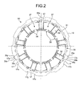
- FIG. 2 is a plan view of the motor stator of the embodiment.
- FIG. 3 is a side view of the motor stator of the embodiment.
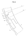
- FIG. 4 is a partial enlarged view of the engagement between a U-shaped groove of a stator iron core and an engagement claw of an insulator of the embodiment.
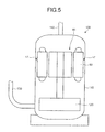
- FIG. 5 is a schematic cross-sectional view of a rotary compressor of the embodiment.
- a motor stator 90 of the embodiment is configured to be built in a rotary compressor 100 (see FIG. 5 ) that compresses refrigerant and discharges the compressed refrigerant.
- the motor stator 90 includes a stator iron core 10, an insulating film 20, and two insulators 30, 30.
- the insulating film 20 is inserted in a slot 11 of the stator iron core 10 to insulate between the slot 11 and a coil 1 (not illustrated).
- the insulators 30, 30 includes upper and lower insulators that are provided to both axial-direction ends 16, 16 of the stator iron core 10, respectively, to insulate between the axial-direction ends 16, 16 and the coil.
- the stator iron core 10 is made of a magnetic steel plate punched into rings, which are stacked to form substantially a cylindrical shape.
- the stator iron core 10 includes a ring-like yoke 12, teeth 13, edges 14, and a plurality of (nine) shallow-bottomed U-shaped grooves 17.
- the teeth 13 extend from the yoke 12 toward the center.
- the edges 14 extend from the teeth 13 in the circumferential direction.
- the U-shaped grooves 17 are formed on the circumference of the yoke 12 in the axial direction and serve as return passages of refrigerant and refrigerant oil in the rotary compressor 100.
- the U-shaped grooves 17 each include side walls 17x and 17y.
- the side walls 17x and 17y extend in the redial direction from both circumferential-direction ends of the bottom of the U-shaped groove 17 extending in the axial direction, respectively.
- the side wall 17x located counterclockwise from the center of the bottom of the U-shaped groove 17 is referred to as a first side wall
- the side wall 17y located clockwise is referred to as a second side wall.
- the slot 11 is formed as a fan-shaped space surrounded by the yoke 12, the teeth 13, and the edges 14.
- a slot opening 15 is formed between an opposing pair of the edges 14.
- the insulating film 20 is made of a polyester film or the like, and is bent into a cylinder having a fan-shaped cross section to be in close contact with the inner surface of the slot 11. Both circumferential-direction ends of the insulating film 20 are bent toward the inside of the cylinder to form bent portions 21. A film opening 23 is formed between the bent portions 21. The film opening 23 has a width equal to or wider than the slot opening 15.
- the insulating file 20 is longer than the stator iron core 10 in the axial direction. Accordingly, when the insulating film 20 is inserted in the slot 11, an axial-direction end 22 of the insulating film 20 protrudes from the axial direction end 16 of the stator iron core 10.
- the insulating film 20 need not necessarily be made of a polyester film, and may be made of various materials depending on a machine to which the motor is applied. For example, if the motor is applied to a compressor that compresses refrigerant, a flame-proof insulating film, such as a polyphenylene sulfide film, an insulating film made of aramid fiber, etc., is preferably used instead of a polyester film.
- a flame-proof insulating film such as a polyphenylene sulfide film, an insulating film made of aramid fiber, etc.
- the insulators 30 are each formed into a short cylinder by resin molding.
- the insulator 30 includes an outer circumference wall 31, hoisting drums 32, insulator edges 33, inner guards 34, and three engagement claws 35a, 35b, and 35c.
- the outer circumference wall 31 is located on the yoke 12 of the stator iron core 10.
- the hoisting drums 32 radially extend from the outer circumference wall 31 on the stator iron core 10 side (lower side) toward the center (inside) and covers the teeth 13 of the stator iron core 10.
- the insulator edges 33 extend from the inner ends of the hoisting drums 32 in the circumferential direction.
- the inner guards 34 are provided to the insulator edges 33 on the side opposite the stator iron core 10 (i.e., the inner guards 34 extend from the inner ends of the hoisting drums 32 in the axial direction).
- the engagement claws 35a, 35b, and 35c are located spaced apart in the circumferential direction on the outside of the outer circumference wall 31 on the stator iron core 10 side (lower side).
- the engagement claws 35a, 35b, and 35c are fitted in the axial-direction ends of the U-shaped grooves 17, respectively.
- the insulators 30 serves as insulating coatings on the axial-direction ends 16, 16 of the stator iron core 10. There may be four or more engagement claws.
- the engagement claws 35a, 35b, and 35c each include two side portions 35x and 35y.
- the side portion 35x located counterclockwise is referred to as a first circumferential side portion
- the side portion 35y located clockwise is referred to as a second circumferential side portion.
- An insulator slot 37 and an insulator opening 36 are formed in substantially the same shape as the slot 11 and the slot opening 15 of the stator iron core 10, respectively, such that they are surrounded by the outer circumference wall 31 on the stator iron core 10 side, the hoisting drums 32, and the insulator edges 33.
- a slit 75 formed in the outer circumference wall 31 is used to pass through a neutral wire and a crossover 50 of the coil and also to thin the outer circumference wall 31.
- the outer diameter M of the end is smaller than the outer diameter N of the stator iron core 10 (i.e., the inner diameter of a housing 110 of the rotary compressor 100) and the circumferential-direction width is smaller than the width of the U-shaped grooves 17 such that the engagement claws 35a, 35b, and 35c are located in the return passages (the U-shaped grooves 17) of refrigerant and refrigerant oil in the housing 110.
- each of the engagement claws 35a, 35b, and 35c there is a space between the end of each of the engagement claws 35a, 35b, and 35c and the inner wall of the housing 110 and at least either between the first circumferential-direction side portion 35x of each of the engagement claws 35a, 35b, and 35c and the first side wall 17x of the U-shaped groove 17 or between the second circumferential-direction side portion 35y and the second side wall 17y.
- the refrigerant oil is not prevented from flowing down along the inner wall of the housing 110.
- the insulator 30 is arranged such that one of the engagement claws 35a, 35b, and 35c, for example, the engagement claw 35b is located with the first circumferential-direction side portion 35x in contact with the first side wall 17x of one of the U-shaped grooves 17, the engagement claw 35c is located with the second circumferential-direction side portion 35y in contact with the second side wall 17y of another one of the U-shaped grooves 17, and the engagement claw 35a is located in the circumferential-direction center of still another one of the U-shaped grooves 17.
- those near the engagement claw 35a can be set as where the coil starts winding to a winding machine without error.
- the engagement claws 35b and 35c arranged as above are locked because the first circumferential-direction side portion 35x of the engagement claw 35b is in contact with the first side wall 17x of one of the U-shaped grooves 17, and the second circumferential-direction side portion 35y of the engagement claw 35c is in contact with the second side wall 17y of another one of the U-shaped grooves 17.
- the engagement claws 35b and 35c (or the three engagement claws 35a, 35b, and 35c) are located at different positions in the U-shaped grooves 17. Accordingly, the upper and lower insulators 30, 30 can be aligned in the circumferential direction by visually checking the engagement claws 35b and 35c (and 35a) from the side of the motor stator 90.
- the insulator 30 is not displaced in the circumferential direction when the coil is wound. Thus, insulation failure can be prevented. Moreover, since the existing U-shaped grooves 17 are used to lock the engagement claws 35b and 35c, there is no increase in the fabrication cost of the stator iron core 10.
- the rotary compressor 100 can be obtained.
- the rotary compressor 100 sucks in a low-pressure refrigerant gas from an accumulator (not illustrated) through a low-pressure communication pipe 130.
- the rotary compressor 100 then compresses the refrigerant gas in the refrigerant gas compressor 120 and discharges the compressed gas from a discharge pipe 140.
- the U-shaped grooves 17 of the stator iron core 10 serve as return passages of refrigerant oil lubricating the refrigerant gas compressor 120.
Landscapes
- Engineering & Computer Science (AREA)
- Power Engineering (AREA)
- Insulation, Fastening Of Motor, Generator Windings (AREA)
- Compressor (AREA)
- Iron Core Of Rotating Electric Machines (AREA)
Abstract
Description
- The embodiments discussed herein are directed to a rotary compressor that compresses refrigerant and discharges the compressed refrigerant and a stator of a motor built in the rotary compressor.
- A conventionally known motor is provided with a rotor and a stator that is located on the outside of the rotor in the radial direction. The stator includes a stator core, insulators assembled with both axial-direction end surfaces of the stator core, respectively, and a coil wound around the stator core and the insulators. The stator core and the insulators are provided with a wrong assembly prevention mechanism that prevents the insulators from being wrongly assembled with the end surfaces of the stator core. The wrong assembly prevention mechanism prevents the wrong assembly of each insulator with respect to a circumferential position on each end surface of the stator core.
- For example, Japanese Laid-open Patent Publication No.
2008-167516 - With the conventional technology, there are a plurality of engagement holes provided to the stator core and a plurality of engagement claws provided to the insulators that engage the engagement holes, respectively. When a winding wire is wound around the stator core and the insulators by a winding machine, a nozzle of the winding machine moves in the circumferential direction as passing through a slot upward or downward and moves to the next slot. At this time, if a circumferential force acts on the insulator due to the tension of the winding wire, the insulator is not displaced in the circumferential direction with respect to the stator core.
- With the conventional technology, however, the stator core is provided with the engagement holes dedicated to engage the engagement claws, which increases the fabrication cost of the stator core.
- Accordingly, it is an object in one aspect of an embodiment of the invention to provide a motor stator in which an insulator is not displaced in the circumferential direction when a coil is wound and there is no increase in the fabrication cost of a stator core, and a rotary compressor having the motor stator built therein.
- According to an aspect of an embodiment, a motor stator includes a substantially cylindrical stator iron core and insulators. The stator iron core includes a ring-like yoke, teeth, and a plurality of U-shaped grooves. The teeth radially extend from the yoke toward the center. The U-shaped grooves are formed on the circumference of the yoke in the axial direction. The insulators, as insulating coatings on axial-direction ends of the stator iron core, includes a ring-like outer circumference wall, a plurality of hoisting drums, inner guards, and at least three engagement claws. The hoisting drums radially extend from the outer circumference wall toward the center. The inner guards extend from inner ends of the hoisting drums in the axial direction, respectively. The engagement claws are located spaced apart in the circumferential direction on the outside of the outer circumference wall and fitted in axial-direction of the U-shaped grooves, respectively. One of the engagement claws is arranged such that a first circumferential-direction side portion of the engagement claw is in contact with a first side wall of one of the U-shaped grooves. Another one of the engagement claws is arranged such that a second circumferential-direction side portion of the engagement claw is in contact with a second side wall of another one of the U-shaped grooves.
- According to another aspect of an embodiment, a rotary compressor includes a housing that houses a motor including a motor stator and a refrigerant gas compressor driven by the motor. The motor stator includes a substantially cylindrical stator iron core and insulators. The stator iron core includes a ring-like yoke, teeth, and a plurality of U-shaped grooves. The teeth radially extend from the yoke toward the center. The U-shaped grooves are formed on the circumference of the yoke in axial direction. The insulators, as insulating on axial-direction ends of the stator iron core, includes a ring-like outer circumference wall, a plurality of hoisting drums, inner guards, and at least three engagement claws. The hoisting drums radially extend from the circumference wall toward the center. The inner guards extend from inner ends of the hoisting drums in the axial direction, respectively. The engagement claws are located spaced apart in the circumferential direction on the outside of the outer circumference wall and fitted in axial-direction ends of the U-shaped grooves, respectively. One of the engagement claws is arranged such that a first circumferential-direction side portion of the engagement claw is in contact with a first side wall of one of the U-shaped grooves. Another one of the engagement claws is arranged such that a second circumferential-direction side portion of the engagement claw is in contact with a second side wall of another one of the U-shaped grooves. The U-shaped grooves of the stator iron core serve as return passages of refrigerant oil lubricating the refrigerant gas compressor.
-
-
FIG. 1 is an exploded perspective view of a motor stator according to an embodiment; -
FIG. 2 is a plan view of the motor stator of the embodiment; -
FIG. 3 is a side view of the motor stator of the embodiment; -
FIG. 4 is a partial enlarged view of the engagement between a U-shaped groove of a stator iron core and an engagement claw of an insulator of the embodiment; and -
FIG. 5 is a schematic cross-sectional view of a rotary compressor of the embodiment. - Exemplary embodiments of the present invention will be described in detail with reference to the accompanying drawings.
-
FIG. 1 is an exploded perspective view of a motor stator according to an embodiment.FIG. 2 is a plan view of the motor stator of the embodiment.FIG. 3 is a side view of the motor stator of the embodiment.FIG. 4 is a partial enlarged view of the engagement between a U-shaped groove of a stator iron core and an engagement claw of an insulator of the embodiment.FIG. 5 is a schematic cross-sectional view of a rotary compressor of the embodiment. - As illustrated in
FIG. 1 , amotor stator 90 of the embodiment is configured to be built in a rotary compressor 100 (seeFIG. 5 ) that compresses refrigerant and discharges the compressed refrigerant. Themotor stator 90 includes astator iron core 10, aninsulating film 20, and twoinsulators insulating film 20 is inserted in aslot 11 of thestator iron core 10 to insulate between theslot 11 and a coil 1 (not illustrated). Theinsulators stator iron core 10, respectively, to insulate between the axial-direction ends 16, 16 and the coil. - The
stator iron core 10 is made of a magnetic steel plate punched into rings, which are stacked to form substantially a cylindrical shape. Thestator iron core 10 includes a ring-like yoke 12,teeth 13,edges 14, and a plurality of (nine) shallow-bottomed U-shaped grooves 17. Theteeth 13 extend from theyoke 12 toward the center. - The
edges 14 extend from theteeth 13 in the circumferential direction. The U-shapedgrooves 17 are formed on the circumference of theyoke 12 in the axial direction and serve as return passages of refrigerant and refrigerant oil in therotary compressor 100. The U-shapedgrooves 17 each includeside walls side walls U-shaped groove 17 extending in the axial direction, respectively. In the plan view of themotor stator 90 illustrated inFIG. 2 , theside wall 17x located counterclockwise from the center of the bottom of theU-shaped groove 17 is referred to as a first side wall, while theside wall 17y located clockwise is referred to as a second side wall. - The
slot 11 is formed as a fan-shaped space surrounded by theyoke 12, theteeth 13, and theedges 14. Aslot opening 15 is formed between an opposing pair of theedges 14. - As illustrated in
FIG. 1 , the insulatingfilm 20 is made of a polyester film or the like, and is bent into a cylinder having a fan-shaped cross section to be in close contact with the inner surface of theslot 11. Both circumferential-direction ends of the insulatingfilm 20 are bent toward the inside of the cylinder to formbent portions 21. Afilm opening 23 is formed between thebent portions 21. Thefilm opening 23 has a width equal to or wider than theslot opening 15. The insulatingfile 20 is longer than thestator iron core 10 in the axial direction. Accordingly, when the insulatingfilm 20 is inserted in theslot 11, an axial-direction end 22 of the insulatingfilm 20 protrudes from the axial direction end 16 of thestator iron core 10. - The insulating
film 20 need not necessarily be made of a polyester film, and may be made of various materials depending on a machine to which the motor is applied. For example, if the motor is applied to a compressor that compresses refrigerant, a flame-proof insulating film, such as a polyphenylene sulfide film, an insulating film made of aramid fiber, etc., is preferably used instead of a polyester film. - As illustrated in
FIGS. 1 to 3 , theinsulators 30 are each formed into a short cylinder by resin molding. Theinsulator 30 includes anouter circumference wall 31, hoistingdrums 32, insulator edges 33,inner guards 34, and threeengagement claws outer circumference wall 31 is located on theyoke 12 of thestator iron core 10. The hoisting drums 32 radially extend from theouter circumference wall 31 on thestator iron core 10 side (lower side) toward the center (inside) and covers theteeth 13 of thestator iron core 10. The insulator edges 33 extend from the inner ends of the hoistingdrums 32 in the circumferential direction. Theinner guards 34 are provided to the insulator edges 33 on the side opposite the stator iron core 10 (i.e., theinner guards 34 extend from the inner ends of the hoistingdrums 32 in the axial direction). Theengagement claws outer circumference wall 31 on thestator iron core 10 side (lower side). Theengagement claws U-shaped grooves 17, respectively. Theinsulators 30 serves as insulating coatings on the axial-direction ends 16, 16 of thestator iron core 10. There may be four or more engagement claws. Theengagement claws side portions motor stator 90 illustrated inFIG. 2 , theside portion 35x located counterclockwise is referred to as a first circumferential side portion, while theside portion 35y located clockwise is referred to as a second circumferential side portion. - An
insulator slot 37 and aninsulator opening 36 are formed in substantially the same shape as theslot 11 and the slot opening 15 of thestator iron core 10, respectively, such that they are surrounded by theouter circumference wall 31 on thestator iron core 10 side, the hoistingdrums 32, and the insulator edges 33. - A slit 75 formed in the
outer circumference wall 31 is used to pass through a neutral wire and acrossover 50 of the coil and also to thin theouter circumference wall 31. As illustrated inFIG. 4 , regarding theengagement claws housing 110 of the rotary compressor 100) and the circumferential-direction width is smaller than the width of theU-shaped grooves 17 such that theengagement claws housing 110. Accordingly, there is a space between the end of each of theengagement claws housing 110 and at least either between the first circumferential-direction side portion 35x of each of theengagement claws first side wall 17x of theU-shaped groove 17 or between the second circumferential-direction side portion 35y and thesecond side wall 17y. Thus, the refrigerant oil is not prevented from flowing down along the inner wall of thehousing 110. - A description will be given of a characteristic structure of the
insulator 30 of the embodiment. Theinsulator 30 is arranged such that one of theengagement claws engagement claw 35b is located with the first circumferential-direction side portion 35x in contact with thefirst side wall 17x of one of theU-shaped grooves 17, theengagement claw 35c is located with the second circumferential-direction side portion 35y in contact with thesecond side wall 17y of another one of theU-shaped grooves 17, and theengagement claw 35a is located in the circumferential-direction center of still another one of theU-shaped grooves 17. Using theengagement claw 35a located in the circumferential-direction center of theU-shaped groove 17 as a reference, among theteeth 13 and the hoisting drums 32, those near theengagement claw 35a can be set as where the coil starts winding to a winding machine without error. - The
engagement claws direction side portion 35x of theengagement claw 35b is in contact with thefirst side wall 17x of one of theU-shaped grooves 17, and the second circumferential-direction side portion 35y of theengagement claw 35c is in contact with thesecond side wall 17y of another one of theU-shaped grooves 17. Accordingly, when a nozzle of the winding machine moves in the circumferential direction as passing through theslot 11 upward or downward or moves to thenext slot 11 to wind a winding wire around theteeth 13 of thestator iron core 10 via theinsulators 30 and the insulatingfilm 20 by the winding machine, if a circumferential force acts on theinsulator 30 due to the tension of the winding wire, theinsulator 30 is not displaced in the circumferential direction with respect to thestator iron core 10. - Besides, the
engagement claws engagement claws U-shaped grooves 17. Accordingly, the upper andlower insulators engagement claws motor stator 90. - As described above, in the
motor stator 90 according to the embodiment, theinsulator 30 is not displaced in the circumferential direction when the coil is wound. Thus, insulation failure can be prevented. Moreover, since the existingU-shaped grooves 17 are used to lock theengagement claws stator iron core 10. - As illustrated in
FIG. 5 , by installing amotor 80 including themotor stator 90 of the embodiment and arefrigerant gas compressor 120 driven by themotor 80 in thehousing 110, therotary compressor 100 can be obtained. Therotary compressor 100 sucks in a low-pressure refrigerant gas from an accumulator (not illustrated) through a low-pressure communication pipe 130. Therotary compressor 100 then compresses the refrigerant gas in therefrigerant gas compressor 120 and discharges the compressed gas from adischarge pipe 140. In therotary compressor 100 including themotor stator 90 of the embodiment, theU-shaped grooves 17 of thestator iron core 10 serve as return passages of refrigerant oil lubricating therefrigerant gas compressor 120.
Claims (4)
- A motor stator comprising:a substantially cylindrical stator iron core (10) including
a ring-like yoke (12),
teeth (13) that radially extend from the yoke (12) toward a center, and
a plurality of U-shaped grooves (17) that are formed on a circumference of the yoke (12) in an axial direction; andinsulators (30) as insulating coatings on axial-direction ends (16) of the stator iron core (10), the insulators (30) each including :a ring-like outer circumference wall (31),a plurality of hoisting drums (32) that radially extend from the outer circumference wall (31) toward a center,inner guards (34) that extend from inner ends of the hoisting drums (32) in the axial direction, respectively, andat least three engagement claws (35a, 35b, 35c) that are located spaced apart in a circumferential direction on outside of the outer circumference wall (31) and fitted in axial-direction ends of the U-shaped grooves (17), respectively,wherein one of the engagement claws (35a, 35b, 35c) is arranged such that a first circumferential-direction side portion (35x) of the engagement claw (35b) is in contact with a first side wall (17x) of one of the U-shaped grooves (17), andanother one of the engagement claws (35a, 35b, and 35c) is arranged such that a second circumferential-direction side portion (35y) of the engagement claw (35c) is in contact with a second side wall (17y) of another one of the U-shaped grooves (17). - The motor stator according to claim 1, wherein
the insulators (30) include upper and lower insulators (30), and
still another one of the engagement claws (35a, 35b, and 35c) is located in a circumferential-direction center of still another one of the U-shaped grooves (17) and is used as a reference to align the upper and lower insulators (30) in the circumferential direction or to start winding a coil. - A rotary compressor comprising a housing (110) that houses a motor (80) including a motor stator (90) and a refrigerant compressor (120) driven by the motor (80), the motor stator (90) including
a substantially cylindrical stator iron core (10) including
a ring-like yoke (12),
teeth (13) that radially extend from the yoke (12) toward a center, and
a plurality of U-shaped grooves that are formed on a circumference of the yoke (12) in an axial direction; and
insulators (30) as insulating coatings on axial-direction ends (16) of the stator iron core (10), the insulators (30) each including
a ring-like outer circumference wall (31),
a plurality of hoisting drums (32) that radially extend from the outer circumference wall (31) toward a center,
inner guards (34) that extend from inner ends of the hoisting drums (32) in the axial direction, respectively, and
at least three engagement claws (35a, 35b, 35c) that are located spaced apart in a circumferential direction on outside of the outer circumference wall (31) and fitted in axial-direction ends of the U-shaped grooves (17), respectively,
wherein one of the engagement claws (35a, 35b, 35c) is arranged such that a first circumferential-direction side portion (35x) of the engagement claw (35b) is in contact with a first side wall (17x) of one of the U-shaped grooves (17),
another one of the engagement claws (35a, 35b, and 35c) is arranged such that a second circumferential-direction side portion (35y) of the engagement claw (35c) is in contact with a second side wall (17y) of another one of the U-shaped grooves (17), and
the U-shaped grooves (17) of the stator iron core (10) serve as return passages of refrigerant oil lubricating the refrigerant gas compressor (120). - The rotary compressor according to claim 3, wherein an outer diameter of an end of the engagement claws (35a, 35b, and 35c) is smaller than an inner diameter of the hosing.
Applications Claiming Priority (1)
| Application Number | Priority Date | Filing Date | Title |
|---|---|---|---|
| JP2010082622A JP5482383B2 (en) | 2010-03-31 | 2010-03-31 | Electric motor stator and rotary compressor |
Publications (3)
| Publication Number | Publication Date |
|---|---|
| EP2372879A2 true EP2372879A2 (en) | 2011-10-05 |
| EP2372879A3 EP2372879A3 (en) | 2016-12-28 |
| EP2372879B1 EP2372879B1 (en) | 2019-12-18 |
Family
ID=44278568
Family Applications (1)
| Application Number | Title | Priority Date | Filing Date |
|---|---|---|---|
| EP11160704.0A Active EP2372879B1 (en) | 2010-03-31 | 2011-03-31 | Motor stator and rotary compressor |
Country Status (5)
| Country | Link |
|---|---|
| US (1) | US8608462B2 (en) |
| EP (1) | EP2372879B1 (en) |
| JP (1) | JP5482383B2 (en) |
| CN (1) | CN102208839B (en) |
| AU (1) | AU2011201412B2 (en) |
Cited By (6)
| Publication number | Priority date | Publication date | Assignee | Title |
|---|---|---|---|---|
| FR2991831A1 (en) * | 2012-06-12 | 2013-12-13 | Valeo Equip Electr Moteur | INSULATING ELEMENT FOR STATOR OF ELECTRIC MACHINE |
| FR2991830A1 (en) * | 2012-06-12 | 2013-12-13 | Valeo Equip Electr Moteur | ELEMENT FOR MAINTAINING WINDING WIRES OF A STATOR OF ELECTRIC MACHINE |
| WO2014095819A3 (en) * | 2012-12-20 | 2014-12-11 | Hilti Aktiengesellschaft | Two-component isolation of bl stators |
| EP2611000A3 (en) * | 2011-12-28 | 2017-07-26 | Fujitsu General Limited | Electric motor |
| EP3624310A1 (en) * | 2018-09-11 | 2020-03-18 | Lakeview Innovation Ltd. | Stator with compact isolation and method for manufacturing such a stator |
| WO2021122255A1 (en) * | 2019-12-17 | 2021-06-24 | Valeo Siemens Eautomotive Germany Gmbh | Insulating device, stator device, electrical machine and method for producing a stator device |
Families Citing this family (21)
| Publication number | Priority date | Publication date | Assignee | Title |
|---|---|---|---|---|
| JP5917109B2 (en) * | 2011-11-29 | 2016-05-11 | アイチエレック株式会社 | End insulating member, stator and rotating machine |
| US9143015B2 (en) | 2012-05-23 | 2015-09-22 | Black & Decker Inc. | Brush holder for a brush assembly for a power tool motor |
| DE102012223976A1 (en) | 2012-12-20 | 2014-06-26 | Hilti Aktiengesellschaft | Stator pressed with winding head support |
| CN104079086A (en) * | 2013-03-29 | 2014-10-01 | 珠海格力节能环保制冷技术研究中心有限公司 | Stator, motor with stator and compressor |
| JP5950865B2 (en) * | 2013-05-14 | 2016-07-13 | ジョンソンコントロールズ ヒタチ エア コンディショニング テクノロジー(ホンコン)リミテッド | Electric motor and air conditioner using the same |
| CN103580313B (en) * | 2013-10-30 | 2017-02-08 | 广东美芝精密制造有限公司 | Stator of motor, motor provided with same and compressor |
| JP5741747B1 (en) | 2014-03-28 | 2015-07-01 | 株式会社富士通ゼネラル | Insulator and brushless DC motor using the same |
| DE102015200095B4 (en) | 2015-01-07 | 2026-03-19 | Robert Bosch Gmbh | Stator for an electric machine and method for manufacturing one |
| CN104578474A (en) * | 2015-01-30 | 2015-04-29 | 安徽美芝制冷设备有限公司 | Stator component and compressor with same |
| JP6398954B2 (en) * | 2015-11-17 | 2018-10-03 | 株式会社デンソー | Rotating electric machine |
| JP6849326B2 (en) * | 2016-06-20 | 2021-03-24 | マブチモーター株式会社 | Stator and motor |
| JP6428739B2 (en) * | 2016-09-30 | 2018-11-28 | 株式会社富士通ゼネラル | Compressor |
| JP2019180216A (en) * | 2018-03-30 | 2019-10-17 | 株式会社豊田自動織機 | Stator of rotary electric machine and the rotary electric machine |
| JP2020022242A (en) * | 2018-07-31 | 2020-02-06 | 日立グローバルライフソリューションズ株式会社 | Stator, motor including the same, and compressor |
| JP7326770B2 (en) | 2019-02-28 | 2023-08-16 | 株式会社富士通ゼネラル | motor and compressor |
| WO2020240735A1 (en) * | 2019-05-29 | 2020-12-03 | 三菱電機株式会社 | Electric motor and compressor equipped with same |
| DE102019124206A1 (en) * | 2019-09-10 | 2021-03-11 | Audi Ag | Electrical machine and method for applying at least one winding to a winding carrier of an electrical machine |
| JP7770913B2 (en) * | 2021-12-27 | 2025-11-17 | 愛知電機株式会社 | Electric motors and compressors |
| JP2023097280A (en) | 2021-12-27 | 2023-07-07 | 愛知電機株式会社 | electric motor and compressor |
| JP7824074B2 (en) | 2021-12-27 | 2026-03-04 | 愛知電機株式会社 | Electric motors and compressors |
| JP7807914B2 (en) | 2021-12-27 | 2026-01-28 | 愛知電機株式会社 | Electric motors and compressors |
Citations (1)
| Publication number | Priority date | Publication date | Assignee | Title |
|---|---|---|---|---|
| JP2008167516A (en) | 2006-12-27 | 2008-07-17 | Daikin Ind Ltd | Motor and compressor |
Family Cites Families (10)
| Publication number | Priority date | Publication date | Assignee | Title |
|---|---|---|---|---|
| US4075522A (en) * | 1976-08-16 | 1978-02-21 | General Motors Corporation | Self clamping armature casing for an electric motor driven fluid pump |
| US4765054A (en) * | 1983-08-11 | 1988-08-23 | Black & Decker, Inc. | Method of making a field subassembly |
| US4603273A (en) * | 1985-08-14 | 1986-07-29 | Westinghouse Electric Corp. | Dynamoelectric machine with extended cleat assembly |
| US5398397A (en) * | 1993-08-04 | 1995-03-21 | A. O. Smith Corporation | Method of manufacturing an electric vehicle |
| TW552352B (en) * | 1999-06-29 | 2003-09-11 | Sanyo Electric Co | Sealed rotary compressor |
| US7414347B2 (en) * | 2004-03-23 | 2008-08-19 | Emerson Electric Co. | End cap for segmented stator |
| WO2008027535A2 (en) * | 2006-09-01 | 2008-03-06 | Sears David B | Insulator for stator assembly of brushless dc motor |
| JP4607964B2 (en) * | 2007-02-26 | 2011-01-05 | 三菱電機株式会社 | Electric motor stator, electric motor, pump, and electric motor manufacturing method |
| JP5353017B2 (en) * | 2008-01-25 | 2013-11-27 | ダイキン工業株式会社 | Compressor |
| DE102008024378A1 (en) * | 2008-05-20 | 2009-12-03 | Miele & Cie. Kg | Electric motor with sensor and / or thermal protection switch |
-
2010
- 2010-03-31 JP JP2010082622A patent/JP5482383B2/en not_active Expired - Fee Related
-
2011
- 2011-03-28 AU AU2011201412A patent/AU2011201412B2/en not_active Ceased
- 2011-03-29 US US13/074,448 patent/US8608462B2/en not_active Expired - Fee Related
- 2011-03-30 CN CN201110079242.0A patent/CN102208839B/en not_active Expired - Fee Related
- 2011-03-31 EP EP11160704.0A patent/EP2372879B1/en active Active
Patent Citations (1)
| Publication number | Priority date | Publication date | Assignee | Title |
|---|---|---|---|---|
| JP2008167516A (en) | 2006-12-27 | 2008-07-17 | Daikin Ind Ltd | Motor and compressor |
Cited By (8)
| Publication number | Priority date | Publication date | Assignee | Title |
|---|---|---|---|---|
| EP2611000A3 (en) * | 2011-12-28 | 2017-07-26 | Fujitsu General Limited | Electric motor |
| FR2991831A1 (en) * | 2012-06-12 | 2013-12-13 | Valeo Equip Electr Moteur | INSULATING ELEMENT FOR STATOR OF ELECTRIC MACHINE |
| FR2991830A1 (en) * | 2012-06-12 | 2013-12-13 | Valeo Equip Electr Moteur | ELEMENT FOR MAINTAINING WINDING WIRES OF A STATOR OF ELECTRIC MACHINE |
| WO2013186459A3 (en) * | 2012-06-12 | 2014-12-24 | Valeo Equipements Electriques Moteur | Insulating element for electric machine stator |
| WO2013186460A3 (en) * | 2012-06-12 | 2014-12-24 | Valeo Equipements Electriques Moteur | Element for holding winding wires of an electric machine stator |
| WO2014095819A3 (en) * | 2012-12-20 | 2014-12-11 | Hilti Aktiengesellschaft | Two-component isolation of bl stators |
| EP3624310A1 (en) * | 2018-09-11 | 2020-03-18 | Lakeview Innovation Ltd. | Stator with compact isolation and method for manufacturing such a stator |
| WO2021122255A1 (en) * | 2019-12-17 | 2021-06-24 | Valeo Siemens Eautomotive Germany Gmbh | Insulating device, stator device, electrical machine and method for producing a stator device |
Also Published As
| Publication number | Publication date |
|---|---|
| JP5482383B2 (en) | 2014-05-07 |
| EP2372879B1 (en) | 2019-12-18 |
| US20110243768A1 (en) | 2011-10-06 |
| JP2011217503A (en) | 2011-10-27 |
| AU2011201412B2 (en) | 2014-11-20 |
| CN102208839B (en) | 2015-05-13 |
| US8608462B2 (en) | 2013-12-17 |
| AU2011201412A1 (en) | 2011-10-20 |
| EP2372879A3 (en) | 2016-12-28 |
| CN102208839A (en) | 2011-10-05 |
Similar Documents
| Publication | Publication Date | Title |
|---|---|---|
| EP2372879A2 (en) | Motor stator and rotary compressor | |
| EP2320539B1 (en) | Rotary machine stator | |
| US9685832B2 (en) | Stator insulator structure with reduced residual stress and improved durability | |
| CN101494399B (en) | Motor and motor integrated pump with the motor | |
| EP2159906A2 (en) | Oil cooling system for motor | |
| US12149138B2 (en) | Electrical insulator assembly, stator and motor | |
| KR19990023654A (en) | Core formed by lamination of rotating laminate, electric motor and core manufacturing method including the core | |
| US20190312473A1 (en) | Rotary electric machine and rotor mounted therein | |
| JP2010193706A (en) | Stator of ac motor | |
| EP3285370B1 (en) | Stator, and motor and compressor which have same | |
| US10284041B2 (en) | Stator of motor having insulating structure | |
| JP2011139549A (en) | Insulator and stator of motor | |
| KR102796969B1 (en) | Motor | |
| US12101006B2 (en) | Motor, and method for manufacturing stator provided in motor | |
| CN114977595A (en) | Stator and Motor | |
| US20260058504A1 (en) | Stator core | |
| JP2016046890A (en) | Slot insulation paper, stator, rotary electric machine, and manufacturing method of stator | |
| JP2014050290A (en) | Stator, motor, and compressor | |
| JP7151118B2 (en) | Rotating electric machine | |
| CN114243982B (en) | Stator assembly and motor | |
| JP6854664B2 (en) | Stator and compressor | |
| JP2016192880A (en) | Stator, motor, and compressor provided with lead wire restraints | |
| US20090127968A1 (en) | Electrical machine with an end-side deflection of electrical conductors | |
| EP4207563A1 (en) | Insulator, motor, and applied device | |
| US11515766B2 (en) | Manufacturing method of electric pump |
Legal Events
| Date | Code | Title | Description |
|---|---|---|---|
| PUAI | Public reference made under article 153(3) epc to a published international application that has entered the european phase |
Free format text: ORIGINAL CODE: 0009012 |
|
| AK | Designated contracting states |
Kind code of ref document: A2 Designated state(s): AL AT BE BG CH CY CZ DE DK EE ES FI FR GB GR HR HU IE IS IT LI LT LU LV MC MK MT NL NO PL PT RO RS SE SI SK SM TR |
|
| AX | Request for extension of the european patent |
Extension state: BA ME |
|
| PUAL | Search report despatched |
Free format text: ORIGINAL CODE: 0009013 |
|
| AK | Designated contracting states |
Kind code of ref document: A3 Designated state(s): AL AT BE BG CH CY CZ DE DK EE ES FI FR GB GR HR HU IE IS IT LI LT LU LV MC MK MT NL NO PL PT RO RS SE SI SK SM TR |
|
| AX | Request for extension of the european patent |
Extension state: BA ME |
|
| RIC1 | Information provided on ipc code assigned before grant |
Ipc: H02K 1/14 20060101ALI20161118BHEP Ipc: H02K 3/52 20060101ALI20161118BHEP Ipc: H02K 3/34 20060101AFI20161118BHEP |
|
| STAA | Information on the status of an ep patent application or granted ep patent |
Free format text: STATUS: REQUEST FOR EXAMINATION WAS MADE |
|
| 17P | Request for examination filed |
Effective date: 20170627 |
|
| RBV | Designated contracting states (corrected) |
Designated state(s): AL AT BE BG CH CY CZ DE DK EE ES FI FR GB GR HR HU IE IS IT LI LT LU LV MC MK MT NL NO PL PT RO RS SE SI SK SM TR |
|
| GRAP | Despatch of communication of intention to grant a patent |
Free format text: ORIGINAL CODE: EPIDOSNIGR1 |
|
| STAA | Information on the status of an ep patent application or granted ep patent |
Free format text: STATUS: GRANT OF PATENT IS INTENDED |
|
| INTG | Intention to grant announced |
Effective date: 20190607 |
|
| GRAJ | Information related to disapproval of communication of intention to grant by the applicant or resumption of examination proceedings by the epo deleted |
Free format text: ORIGINAL CODE: EPIDOSDIGR1 |
|
| STAA | Information on the status of an ep patent application or granted ep patent |
Free format text: STATUS: REQUEST FOR EXAMINATION WAS MADE |
|
| GRAR | Information related to intention to grant a patent recorded |
Free format text: ORIGINAL CODE: EPIDOSNIGR71 |
|
| GRAS | Grant fee paid |
Free format text: ORIGINAL CODE: EPIDOSNIGR3 |
|
| STAA | Information on the status of an ep patent application or granted ep patent |
Free format text: STATUS: GRANT OF PATENT IS INTENDED |
|
| GRAJ | Information related to disapproval of communication of intention to grant by the applicant or resumption of examination proceedings by the epo deleted |
Free format text: ORIGINAL CODE: EPIDOSDIGR1 |
|
| GRAP | Despatch of communication of intention to grant a patent |
Free format text: ORIGINAL CODE: EPIDOSNIGR1 |
|
| GRAS | Grant fee paid |
Free format text: ORIGINAL CODE: EPIDOSNIGR3 |
|
| GRAJ | Information related to disapproval of communication of intention to grant by the applicant or resumption of examination proceedings by the epo deleted |
Free format text: ORIGINAL CODE: EPIDOSDIGR1 |
|
| GRAP | Despatch of communication of intention to grant a patent |
Free format text: ORIGINAL CODE: EPIDOSNIGR1 |
|
| GRAS | Grant fee paid |
Free format text: ORIGINAL CODE: EPIDOSNIGR3 |
|
| GRAJ | Information related to disapproval of communication of intention to grant by the applicant or resumption of examination proceedings by the epo deleted |
Free format text: ORIGINAL CODE: EPIDOSDIGR1 |
|
| GRAR | Information related to intention to grant a patent recorded |
Free format text: ORIGINAL CODE: EPIDOSNIGR71 |
|
| GRAS | Grant fee paid |
Free format text: ORIGINAL CODE: EPIDOSNIGR3 |
|
| GRAJ | Information related to disapproval of communication of intention to grant by the applicant or resumption of examination proceedings by the epo deleted |
Free format text: ORIGINAL CODE: EPIDOSDIGR1 |
|
| GRAR | Information related to intention to grant a patent recorded |
Free format text: ORIGINAL CODE: EPIDOSNIGR71 |
|
| GRAS | Grant fee paid |
Free format text: ORIGINAL CODE: EPIDOSNIGR3 |
|
| INTC | Intention to grant announced (deleted) | ||
| GRAA | (expected) grant |
Free format text: ORIGINAL CODE: 0009210 |
|
| STAA | Information on the status of an ep patent application or granted ep patent |
Free format text: STATUS: THE PATENT HAS BEEN GRANTED |
|
| INTG | Intention to grant announced |
Effective date: 20191022 |
|
| INTG | Intention to grant announced |
Effective date: 20191029 |
|
| INTG | Intention to grant announced |
Effective date: 20191107 |
|
| AK | Designated contracting states |
Kind code of ref document: B1 Designated state(s): AL AT BE BG CH CY CZ DE DK EE ES FI FR GB GR HR HU IE IS IT LI LT LU LV MC MK MT NL NO PL PT RO RS SE SI SK SM TR |
|
| REG | Reference to a national code |
Ref country code: GB Ref legal event code: FG4D |
|
| REG | Reference to a national code |
Ref country code: CH Ref legal event code: EP |
|
| REG | Reference to a national code |
Ref country code: DE Ref legal event code: R096 Ref document number: 602011064053 Country of ref document: DE |
|
| REG | Reference to a national code |
Ref country code: IE Ref legal event code: FG4D |
|
| REG | Reference to a national code |
Ref country code: AT Ref legal event code: REF Ref document number: 1215645 Country of ref document: AT Kind code of ref document: T Effective date: 20200115 |
|
| REG | Reference to a national code |
Ref country code: NL Ref legal event code: MP Effective date: 20191218 |
|
| PG25 | Lapsed in a contracting state [announced via postgrant information from national office to epo] |
Ref country code: LT Free format text: LAPSE BECAUSE OF FAILURE TO SUBMIT A TRANSLATION OF THE DESCRIPTION OR TO PAY THE FEE WITHIN THE PRESCRIBED TIME-LIMIT Effective date: 20191218 Ref country code: LV Free format text: LAPSE BECAUSE OF FAILURE TO SUBMIT A TRANSLATION OF THE DESCRIPTION OR TO PAY THE FEE WITHIN THE PRESCRIBED TIME-LIMIT Effective date: 20191218 Ref country code: SE Free format text: LAPSE BECAUSE OF FAILURE TO SUBMIT A TRANSLATION OF THE DESCRIPTION OR TO PAY THE FEE WITHIN THE PRESCRIBED TIME-LIMIT Effective date: 20191218 Ref country code: NO Free format text: LAPSE BECAUSE OF FAILURE TO SUBMIT A TRANSLATION OF THE DESCRIPTION OR TO PAY THE FEE WITHIN THE PRESCRIBED TIME-LIMIT Effective date: 20200318 Ref country code: GR Free format text: LAPSE BECAUSE OF FAILURE TO SUBMIT A TRANSLATION OF THE DESCRIPTION OR TO PAY THE FEE WITHIN THE PRESCRIBED TIME-LIMIT Effective date: 20200319 Ref country code: BG Free format text: LAPSE BECAUSE OF FAILURE TO SUBMIT A TRANSLATION OF THE DESCRIPTION OR TO PAY THE FEE WITHIN THE PRESCRIBED TIME-LIMIT Effective date: 20200318 Ref country code: FI Free format text: LAPSE BECAUSE OF FAILURE TO SUBMIT A TRANSLATION OF THE DESCRIPTION OR TO PAY THE FEE WITHIN THE PRESCRIBED TIME-LIMIT Effective date: 20191218 |
|
| REG | Reference to a national code |
Ref country code: LT Ref legal event code: MG4D |
|
| PG25 | Lapsed in a contracting state [announced via postgrant information from national office to epo] |
Ref country code: RS Free format text: LAPSE BECAUSE OF FAILURE TO SUBMIT A TRANSLATION OF THE DESCRIPTION OR TO PAY THE FEE WITHIN THE PRESCRIBED TIME-LIMIT Effective date: 20191218 Ref country code: HR Free format text: LAPSE BECAUSE OF FAILURE TO SUBMIT A TRANSLATION OF THE DESCRIPTION OR TO PAY THE FEE WITHIN THE PRESCRIBED TIME-LIMIT Effective date: 20191218 |
|
| PG25 | Lapsed in a contracting state [announced via postgrant information from national office to epo] |
Ref country code: AL Free format text: LAPSE BECAUSE OF FAILURE TO SUBMIT A TRANSLATION OF THE DESCRIPTION OR TO PAY THE FEE WITHIN THE PRESCRIBED TIME-LIMIT Effective date: 20191218 |
|
| PG25 | Lapsed in a contracting state [announced via postgrant information from national office to epo] |
Ref country code: PT Free format text: LAPSE BECAUSE OF FAILURE TO SUBMIT A TRANSLATION OF THE DESCRIPTION OR TO PAY THE FEE WITHIN THE PRESCRIBED TIME-LIMIT Effective date: 20200513 Ref country code: EE Free format text: LAPSE BECAUSE OF FAILURE TO SUBMIT A TRANSLATION OF THE DESCRIPTION OR TO PAY THE FEE WITHIN THE PRESCRIBED TIME-LIMIT Effective date: 20191218 Ref country code: NL Free format text: LAPSE BECAUSE OF FAILURE TO SUBMIT A TRANSLATION OF THE DESCRIPTION OR TO PAY THE FEE WITHIN THE PRESCRIBED TIME-LIMIT Effective date: 20191218 Ref country code: RO Free format text: LAPSE BECAUSE OF FAILURE TO SUBMIT A TRANSLATION OF THE DESCRIPTION OR TO PAY THE FEE WITHIN THE PRESCRIBED TIME-LIMIT Effective date: 20191218 Ref country code: CZ Free format text: LAPSE BECAUSE OF FAILURE TO SUBMIT A TRANSLATION OF THE DESCRIPTION OR TO PAY THE FEE WITHIN THE PRESCRIBED TIME-LIMIT Effective date: 20191218 |
|
| PG25 | Lapsed in a contracting state [announced via postgrant information from national office to epo] |
Ref country code: IS Free format text: LAPSE BECAUSE OF FAILURE TO SUBMIT A TRANSLATION OF THE DESCRIPTION OR TO PAY THE FEE WITHIN THE PRESCRIBED TIME-LIMIT Effective date: 20200418 Ref country code: SK Free format text: LAPSE BECAUSE OF FAILURE TO SUBMIT A TRANSLATION OF THE DESCRIPTION OR TO PAY THE FEE WITHIN THE PRESCRIBED TIME-LIMIT Effective date: 20191218 Ref country code: SM Free format text: LAPSE BECAUSE OF FAILURE TO SUBMIT A TRANSLATION OF THE DESCRIPTION OR TO PAY THE FEE WITHIN THE PRESCRIBED TIME-LIMIT Effective date: 20191218 |
|
| REG | Reference to a national code |
Ref country code: DE Ref legal event code: R097 Ref document number: 602011064053 Country of ref document: DE |
|
| REG | Reference to a national code |
Ref country code: AT Ref legal event code: MK05 Ref document number: 1215645 Country of ref document: AT Kind code of ref document: T Effective date: 20191218 |
|
| PLBE | No opposition filed within time limit |
Free format text: ORIGINAL CODE: 0009261 |
|
| STAA | Information on the status of an ep patent application or granted ep patent |
Free format text: STATUS: NO OPPOSITION FILED WITHIN TIME LIMIT |
|
| PG25 | Lapsed in a contracting state [announced via postgrant information from national office to epo] |
Ref country code: DK Free format text: LAPSE BECAUSE OF FAILURE TO SUBMIT A TRANSLATION OF THE DESCRIPTION OR TO PAY THE FEE WITHIN THE PRESCRIBED TIME-LIMIT Effective date: 20191218 Ref country code: ES Free format text: LAPSE BECAUSE OF FAILURE TO SUBMIT A TRANSLATION OF THE DESCRIPTION OR TO PAY THE FEE WITHIN THE PRESCRIBED TIME-LIMIT Effective date: 20191218 Ref country code: MC Free format text: LAPSE BECAUSE OF FAILURE TO SUBMIT A TRANSLATION OF THE DESCRIPTION OR TO PAY THE FEE WITHIN THE PRESCRIBED TIME-LIMIT Effective date: 20191218 |
|
| REG | Reference to a national code |
Ref country code: CH Ref legal event code: PL |
|
| 26N | No opposition filed |
Effective date: 20200921 |
|
| PG25 | Lapsed in a contracting state [announced via postgrant information from national office to epo] |
Ref country code: AT Free format text: LAPSE BECAUSE OF FAILURE TO SUBMIT A TRANSLATION OF THE DESCRIPTION OR TO PAY THE FEE WITHIN THE PRESCRIBED TIME-LIMIT Effective date: 20191218 Ref country code: SI Free format text: LAPSE BECAUSE OF FAILURE TO SUBMIT A TRANSLATION OF THE DESCRIPTION OR TO PAY THE FEE WITHIN THE PRESCRIBED TIME-LIMIT Effective date: 20191218 |
|
| REG | Reference to a national code |
Ref country code: BE Ref legal event code: MM Effective date: 20200331 |
|
| PG25 | Lapsed in a contracting state [announced via postgrant information from national office to epo] |
Ref country code: LU Free format text: LAPSE BECAUSE OF NON-PAYMENT OF DUE FEES Effective date: 20200331 |
|
| PG25 | Lapsed in a contracting state [announced via postgrant information from national office to epo] |
Ref country code: IT Free format text: LAPSE BECAUSE OF FAILURE TO SUBMIT A TRANSLATION OF THE DESCRIPTION OR TO PAY THE FEE WITHIN THE PRESCRIBED TIME-LIMIT Effective date: 20191218 Ref country code: IE Free format text: LAPSE BECAUSE OF NON-PAYMENT OF DUE FEES Effective date: 20200331 Ref country code: CH Free format text: LAPSE BECAUSE OF NON-PAYMENT OF DUE FEES Effective date: 20200331 Ref country code: LI Free format text: LAPSE BECAUSE OF NON-PAYMENT OF DUE FEES Effective date: 20200331 |
|
| PG25 | Lapsed in a contracting state [announced via postgrant information from national office to epo] |
Ref country code: BE Free format text: LAPSE BECAUSE OF NON-PAYMENT OF DUE FEES Effective date: 20200331 Ref country code: PL Free format text: LAPSE BECAUSE OF FAILURE TO SUBMIT A TRANSLATION OF THE DESCRIPTION OR TO PAY THE FEE WITHIN THE PRESCRIBED TIME-LIMIT Effective date: 20191218 |
|
| PGFP | Annual fee paid to national office [announced via postgrant information from national office to epo] |
Ref country code: GB Payment date: 20220210 Year of fee payment: 12 Ref country code: DE Payment date: 20220203 Year of fee payment: 12 |
|
| PG25 | Lapsed in a contracting state [announced via postgrant information from national office to epo] |
Ref country code: TR Free format text: LAPSE BECAUSE OF FAILURE TO SUBMIT A TRANSLATION OF THE DESCRIPTION OR TO PAY THE FEE WITHIN THE PRESCRIBED TIME-LIMIT Effective date: 20191218 Ref country code: MT Free format text: LAPSE BECAUSE OF FAILURE TO SUBMIT A TRANSLATION OF THE DESCRIPTION OR TO PAY THE FEE WITHIN THE PRESCRIBED TIME-LIMIT Effective date: 20191218 Ref country code: CY Free format text: LAPSE BECAUSE OF FAILURE TO SUBMIT A TRANSLATION OF THE DESCRIPTION OR TO PAY THE FEE WITHIN THE PRESCRIBED TIME-LIMIT Effective date: 20191218 |
|
| PGFP | Annual fee paid to national office [announced via postgrant information from national office to epo] |
Ref country code: FR Payment date: 20220209 Year of fee payment: 12 |
|
| PG25 | Lapsed in a contracting state [announced via postgrant information from national office to epo] |
Ref country code: MK Free format text: LAPSE BECAUSE OF FAILURE TO SUBMIT A TRANSLATION OF THE DESCRIPTION OR TO PAY THE FEE WITHIN THE PRESCRIBED TIME-LIMIT Effective date: 20191218 |
|
| REG | Reference to a national code |
Ref country code: DE Ref legal event code: R119 Ref document number: 602011064053 Country of ref document: DE |
|
| GBPC | Gb: european patent ceased through non-payment of renewal fee |
Effective date: 20230331 |
|
| PG25 | Lapsed in a contracting state [announced via postgrant information from national office to epo] |
Ref country code: GB Free format text: LAPSE BECAUSE OF NON-PAYMENT OF DUE FEES Effective date: 20230331 |
|
| PG25 | Lapsed in a contracting state [announced via postgrant information from national office to epo] |
Ref country code: GB Free format text: LAPSE BECAUSE OF NON-PAYMENT OF DUE FEES Effective date: 20230331 Ref country code: FR Free format text: LAPSE BECAUSE OF NON-PAYMENT OF DUE FEES Effective date: 20230331 Ref country code: DE Free format text: LAPSE BECAUSE OF NON-PAYMENT OF DUE FEES Effective date: 20231003 |