EP2372841A1 - Spiral antenna - Google Patents
Spiral antenna Download PDFInfo
- Publication number
- EP2372841A1 EP2372841A1 EP10252152A EP10252152A EP2372841A1 EP 2372841 A1 EP2372841 A1 EP 2372841A1 EP 10252152 A EP10252152 A EP 10252152A EP 10252152 A EP10252152 A EP 10252152A EP 2372841 A1 EP2372841 A1 EP 2372841A1
- Authority
- EP
- European Patent Office
- Prior art keywords
- antenna
- spiral
- radio wave
- wave absorber
- shape
- Prior art date
- Legal status (The legal status is an assumption and is not a legal conclusion. Google has not performed a legal analysis and makes no representation as to the accuracy of the status listed.)
- Withdrawn
Links
- 239000006096 absorbing agent Substances 0.000 claims abstract description 24
- 239000000758 substrate Substances 0.000 claims abstract description 6
- 230000005855 radiation Effects 0.000 description 5
- 238000004088 simulation Methods 0.000 description 4
- 238000000034 method Methods 0.000 description 3
- 238000012986 modification Methods 0.000 description 3
- 230000004048 modification Effects 0.000 description 3
- 230000007423 decrease Effects 0.000 description 2
- 239000000463 material Substances 0.000 description 2
- 230000002542 deteriorative effect Effects 0.000 description 1
- 230000000694 effects Effects 0.000 description 1
- 239000002184 metal Substances 0.000 description 1
- 238000006467 substitution reaction Methods 0.000 description 1
Images


Classifications
-
- H—ELECTRICITY
- H01—ELECTRIC ELEMENTS
- H01Q—ANTENNAS, i.e. RADIO AERIALS
- H01Q9/00—Electrically-short antennas having dimensions not more than twice the operating wavelength and consisting of conductive active radiating elements
- H01Q9/04—Resonant antennas
- H01Q9/16—Resonant antennas with feed intermediate between the extremities of the antenna, e.g. centre-fed dipole
- H01Q9/26—Resonant antennas with feed intermediate between the extremities of the antenna, e.g. centre-fed dipole with folded element or elements, the folded parts being spaced apart a small fraction of operating wavelength
- H01Q9/27—Spiral antennas
-
- H—ELECTRICITY
- H01—ELECTRIC ELEMENTS
- H01Q—ANTENNAS, i.e. RADIO AERIALS
- H01Q17/00—Devices for absorbing waves radiated from an antenna; Combinations of such devices with active antenna elements or systems
-
- H—ELECTRICITY
- H01—ELECTRIC ELEMENTS
- H01Q—ANTENNAS, i.e. RADIO AERIALS
- H01Q19/00—Combinations of primary active antenna elements and units with secondary devices, e.g. with quasi-optical devices, for giving the antenna a desired directional characteristic
- H01Q19/10—Combinations of primary active antenna elements and units with secondary devices, e.g. with quasi-optical devices, for giving the antenna a desired directional characteristic using reflecting surfaces
Definitions
- Embodiments described herein relate generally to a spiral antenna having a wideband characteristic.
- a wideband characteristic and low profile are achieved by inserting a radio wave absorptive material into a space between the antenna and a cavity (see, e.g., Jpn. Pat. Appln. KOKAI Publication No. 2000-252738 ).
- a spiral antenna in general, according to one embodiment, includes an antenna element, a cavity, and a radio wave absorber.
- the spiral antenna is formed into a spiral shape on a dielectric substrate.
- the cavity is formed to have a space with the antenna element.
- the radio wave absorber is placed to cover a terminal end portion of the spiral.
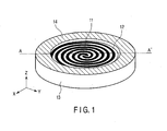
- FIG. 1 is a perspective view of the outer shape of an antenna according to an embodiment of the present embodiment.
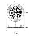
- FIG. 2 is a sectional view showing section A-A' of the antenna shown in FIG. 1 .
- This spiral antenna includes an antenna element 11 formed into spiral patterns on a dielectric substrate 12, a metal cavity 13 for supporting the dielectric substrate 12 so as to form a predetermined space with the antenna element 11, and a radio wave absorber 14 formed to cover the terminal end portions of the spirals of the antenna element 11.
- the radio wave absorber 14 is formed into a ring shape so as to be brought into contact with the cavity 13, and placed on the upper surface of the dielectric substrate 12 so as to cover the terminal end portions of the spirals of the antenna element 11 from above.
- the operation principle of the spiral antenna can be explained by the band theory. That is, radiation occurs from the antenna in a region (one-wavelength circumference) where the wavelength corresponding to the operating frequency and the outer periphery of the antenna are equal. Accordingly, if the outermost periphery of the spiral antenna is smaller than the one-wavelength circumference at the lower-limit operating frequency, no radiation occurs from the spiral antenna at the frequency, and a current flowing through a spiral arm is reflected by the terminal end portion of the spiral arm, thereby deteriorating the characteristics. As a technique of suppressing this reflected wave, a method of spreading a radio wave absorber between the spiral antenna and cavity is generally used. However, this method poses the problem of the increase in weight.
- FIG. 3 shows the frequency responses of the radiation efficiency in the positive Z-axial direction.
- the abscissa represents the frequency [GHz], and the ordinate represents the radiation efficiency [%].
- the broken line represents a simulation result when a radio wave absorber is spread between the spiral antenna and cavity.
- the solid line represents a simulation result when a thin radio wave absorber such as a film is placed on the spiral arms as in this embodiment.
- FIG. 4 shows the frequency responses of the gain in the positive Z-axial direction in the simulations shown in FIG. 3 .
- the abscissa represents the frequency [GHz], and the ordinate represents the absolute gain [dBi].
- FIG. 5 shows the frequency responses of the axial ratio in the positive Z-axial direction in the simulations shown in FIG. 3 .
- the abscissa represents the frequency [GHz], and the ordinate represents the axial ratio [dB].
- the gain and axial ratio remain almost the same even when the radio wave absorber is placed on the spiral arms as in this embodiment.
- the placement region can be made smaller than that when the radio wave absorber is placed between the spiral antenna and cavity. That is, since the amount of radio wave absorber usage decreases, the radiated energy increases. This helps increase the antenna efficiency.
- the radio wave absorber is formed to cover the terminal end portions of the spiral antenna. This makes it possible to increase the antenna efficiency while ensuring the wideband characteristic and low profile.
- the spiral antenna is circular in the above embodiment, but the shape need not be a circle.
- the same effect is obtained even when the spiral shape is a polygon such as a square.
- the circular antenna element has the two arms, and the feeding point in the center. As shown in FIG. 7 , however, it is also possible to form a single-arm spiral antenna. As shown in FIGS. 8 and 9 , the shape of the inner periphery of the radio wave absorber 14 may be a polygonal shape or wavy shape. Furthermore, the radio wave absorber 14 has a ring-like shape in the above embodiment. However, as shown in FIG. 10 , radio wave absorbers may be arranged in portions of the periphery so as to cover only the terminal end portions of the spiral arms of the antenna element 11. As shown in FIG. 11 , it is also possible to combine an antenna device having a polygonal shape such as a square with a circular spiral antenna.
Landscapes
- Aerials With Secondary Devices (AREA)
- Details Of Aerials (AREA)
- Shielding Devices Or Components To Electric Or Magnetic Fields (AREA)
- Control Of Motors That Do Not Use Commutators (AREA)
- Support Of Aerials (AREA)
Abstract
According to one embodiment, a spiral antenna includes an antenna element (11), a cavity (13), and a radio wave absorber (14). The spiral antenna is formed into a spiral shape on a dielectric substrate (12). The cavity is formed to have a space with the antenna element. The radio wave absorber is placed to cover a terminal end portion of the spiral.
Description
- Embodiments described herein relate generally to a spiral antenna having a wideband characteristic.
- In a spiral antenna that radiates electromagnetic waves in the forward direction, a wideband characteristic and low profile are achieved by inserting a radio wave absorptive material into a space between the antenna and a cavity (see, e.g., Jpn. Pat. Appln. KOKAI Publication No.
2000-252738 - If the lower limit of the operating frequency is lowered, however, the space between the cavity and spiral antenna physically widens, so the amount of radio wave absorptive material to be used increases. This makes it difficult to decrease the weight of the antenna.
-
-
FIG. 1 is a perspective view showing the outer shape of a spiral antenna according to an embodiment; -
FIG. 2 is a view showing section A-A' of the spiral antenna shown inFIG. 1 ; -
FIG. 3 is a graph showing the radiation efficiency of the spiral antenna according to the embodiment; -
FIG. 4 is a graph showing the gain of the spiral antenna according to the embodiment; -
FIG. 5 is a graph showing the axial ratio of the spiral antenna according to the embodiment; -
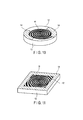
FIG. 6 is a perspective view showing an antenna structure when the spiral shape is a square; -
FIG. 7 is a perspective view showing an antenna structure using a single-fed spiral antenna; -
FIG. 8 is a perspective view showing an antenna structure when a radio wave absorber has a polygonal shape; -
FIG. 9 is a perspective view showing an antenna structure when the radio wave absorber has a wavy shape; -
FIG. 10 is a perspective view showing an antenna structure when radio wave absorbers are arranged in portions of the periphery; and -
FIG. 11 is a perspective view showing an antenna structure when the radio wave absorber has a polygonal shape. - In general, according to one embodiment, a spiral antenna includes an antenna element, a cavity, and a radio wave absorber. The spiral antenna is formed into a spiral shape on a dielectric substrate. The cavity is formed to have a space with the antenna element. The radio wave absorber is placed to cover a terminal end portion of the spiral.
- Embodiments will be explained in detail below with reference to the accompanying drawing.
-
FIG. 1 is a perspective view of the outer shape of an antenna according to an embodiment of the present embodiment.FIG. 2 is a sectional view showing section A-A' of the antenna shown inFIG. 1 . - This spiral antenna includes an
antenna element 11 formed into spiral patterns on adielectric substrate 12, ametal cavity 13 for supporting thedielectric substrate 12 so as to form a predetermined space with theantenna element 11, and a radio wave absorber 14 formed to cover the terminal end portions of the spirals of theantenna element 11. For example, theradio wave absorber 14 is formed into a ring shape so as to be brought into contact with thecavity 13, and placed on the upper surface of thedielectric substrate 12 so as to cover the terminal end portions of the spirals of theantenna element 11 from above. - The operation of the spiral antenna having the structure as described above will be explained below.
- The operation principle of the spiral antenna can be explained by the band theory. That is, radiation occurs from the antenna in a region (one-wavelength circumference) where the wavelength corresponding to the operating frequency and the outer periphery of the antenna are equal. Accordingly, if the outermost periphery of the spiral antenna is smaller than the one-wavelength circumference at the lower-limit operating frequency, no radiation occurs from the spiral antenna at the frequency, and a current flowing through a spiral arm is reflected by the terminal end portion of the spiral arm, thereby deteriorating the characteristics. As a technique of suppressing this reflected wave, a method of spreading a radio wave absorber between the spiral antenna and cavity is generally used. However, this method poses the problem of the increase in weight.
-
FIG. 3 shows the frequency responses of the radiation efficiency in the positive Z-axial direction. The abscissa represents the frequency [GHz], and the ordinate represents the radiation efficiency [%]. The broken line represents a simulation result when a radio wave absorber is spread between the spiral antenna and cavity. The solid line represents a simulation result when a thin radio wave absorber such as a film is placed on the spiral arms as in this embodiment.
FIG. 4 shows the frequency responses of the gain in the positive Z-axial direction in the simulations shown inFIG. 3 . The abscissa represents the frequency [GHz], and the ordinate represents the absolute gain [dBi].FIG. 5 shows the frequency responses of the axial ratio in the positive Z-axial direction in the simulations shown inFIG. 3 . The abscissa represents the frequency [GHz], and the ordinate represents the axial ratio [dB]. - As shown in
FIGS. 4 and5 , the gain and axial ratio remain almost the same even when the radio wave absorber is placed on the spiral arms as in this embodiment. In addition, when the radio wave absorber is placed on the spiral antenna, the placement region can be made smaller than that when the radio wave absorber is placed between the spiral antenna and cavity. That is, since the amount of radio wave absorber usage decreases, the radiated energy increases. This helps increase the antenna efficiency. - In the embodiment as described above, the radio wave absorber is formed to cover the terminal end portions of the spiral antenna. This makes it possible to increase the antenna efficiency while ensuring the wideband characteristic and low profile.
- Note that the present embodiment is not directly limited to the above-mentioned embodiment. For example, the following modifications are possible. The spiral antenna is circular in the above embodiment, but the shape need not be a circle. For example, as shown in
FIG. 6 , the same effect is obtained even when the spiral shape is a polygon such as a square. - Also, in the above embodiment, the circular antenna element has the two arms, and the feeding point in the center. As shown in
FIG. 7 , however, it is also possible to form a single-arm spiral antenna. As shown inFIGS. 8 and 9 , the shape of the inner periphery of theradio wave absorber 14 may be a polygonal shape or wavy shape. Furthermore, theradio wave absorber 14 has a ring-like shape in the above embodiment. However, as shown inFIG. 10 , radio wave absorbers may be arranged in portions of the periphery so as to cover only the terminal end portions of the spiral arms of theantenna element 11. As shown inFIG. 11 , it is also possible to combine an antenna device having a polygonal shape such as a square with a circular spiral antenna. - While certain embodiments have been described, these embodiments have been presented by way of example only, and are not intended to limit the scope of the inventions. Indeed, the novel embodiments described herein may be embodied in a variety of other forms; furthermore, various omissions, substitutions and changes in the form of the embodiments described herein may be made without departing from the spirit of the inventions. The accompanying claims and their equivalents are intended to cover such forms or modifications as would fall within the scope and spirit of the inventions.
Claims (4)
- A spiral antenna characterized by comprising:an antenna element (11) formed into a spiral shape on a dielectric substrate (12);a cavity (13) formed to have a space with the antenna element; anda radio wave absorber (14) placed to cover a terminal end portion of the spiral.
- The antenna according to claim 1, characterized in that the radio wave absorber is formed into a ring shape.
- The antenna according to claim 1, characterized in that the spiral shape of the antenna element is one of a circle or a polygon.
- The antenna according to claim 1, characterized in that the radio wave absorber is formed to have one of a polygonal shape and a wavy shape near a center of the spiral.
Applications Claiming Priority (1)
| Application Number | Priority Date | Filing Date | Title |
|---|---|---|---|
| JP2010076044A JP2011211420A (en) | 2010-03-29 | 2010-03-29 | Spiral antenna |
Publications (1)
| Publication Number | Publication Date |
|---|---|
| EP2372841A1 true EP2372841A1 (en) | 2011-10-05 |
Family
ID=44210056
Family Applications (1)
| Application Number | Title | Priority Date | Filing Date |
|---|---|---|---|
| EP10252152A Withdrawn EP2372841A1 (en) | 2010-03-29 | 2010-12-17 | Spiral antenna |
Country Status (3)
| Country | Link |
|---|---|
| US (1) | US8564500B2 (en) |
| EP (1) | EP2372841A1 (en) |
| JP (1) | JP2011211420A (en) |
Cited By (1)
| Publication number | Priority date | Publication date | Assignee | Title |
|---|---|---|---|---|
| EP4148902B1 (en) * | 2021-09-09 | 2025-11-26 | Thales | Electromagnetic system with angular deviation of the main dispersion lobe of an antenna. |
Families Citing this family (13)
| Publication number | Priority date | Publication date | Assignee | Title |
|---|---|---|---|---|
| FR2965669B1 (en) * | 2010-10-01 | 2012-10-05 | Thales Sa | BROADBAND ANTENNA REFLECTOR FOR CIRCULAR POLARIZED PLANE WIRE ANTENNA AND METHOD FOR PRODUCING THE ANTENNA DEFLECTOR |
| WO2013105086A1 (en) * | 2012-01-05 | 2013-07-18 | Sensible Medical Innovations Ltd. | Electromagnetic (em) probes, methods of using such em probes and systems which use such electromagnetic em probes |
| EP2819244A4 (en) | 2012-02-21 | 2015-01-14 | Fujikura Ltd | Dipole antenna |
| TWI499127B (en) * | 2012-05-11 | 2015-09-01 | Wistron Corp | Antenna structure |
| US9680211B2 (en) | 2014-04-15 | 2017-06-13 | Samsung Electronics Co., Ltd. | Ultra-wideband antenna |
| KR101600009B1 (en) * | 2014-06-05 | 2016-03-04 | (주)위니젠 | Variable spiral antenna |
| US9918145B2 (en) | 2014-09-26 | 2018-03-13 | Mueller International, Llc | High output integrated utility meter reporting system |
| US20160093947A1 (en) * | 2014-09-26 | 2016-03-31 | Yoram Kenig | Flat Spiral Antenna for Utility Meter Reporting Systems and Other Applications |
| US11495886B2 (en) * | 2018-01-04 | 2022-11-08 | The Board Of Trustees Of The University Of Alabama | Cavity-backed spiral antenna with perturbation elements |
| CN109888488B (en) * | 2019-04-04 | 2019-10-25 | 电子科技大学 | Low-profile and low-scattering ultra-broadband phased array based on polarization-selective absorber loading |
| CN111082209B (en) * | 2019-12-31 | 2021-09-21 | 上海微波技术研究所(中国电子科技集团公司第五十研究所) | Low-profile planar helical antenna adopting novel feed mode |
| WO2023004549A1 (en) * | 2021-07-26 | 2023-02-02 | 华为技术有限公司 | Wave-absorbing structure, antenna apparatus, detection apparatus, and terminal device |
| JP7834609B2 (en) * | 2022-08-30 | 2026-03-24 | 株式会社東芝 | Antenna equipment |
Citations (4)
| Publication number | Priority date | Publication date | Assignee | Title |
|---|---|---|---|---|
| JPH06152225A (en) * | 1992-10-30 | 1994-05-31 | Tokimec Inc | Spiral antenna |
| JPH11163622A (en) * | 1997-11-28 | 1999-06-18 | Mitsubishi Electric Corp | Spiral antenna |
| JP2000252738A (en) | 1999-03-02 | 2000-09-14 | Mitsubishi Electric Corp | Microstrip spiral antenna |
| WO2002029928A2 (en) * | 2000-10-02 | 2002-04-11 | Israel Aircraft Industries Ltd. | Slot spiral miniaturized antenna |
Family Cites Families (6)
| Publication number | Priority date | Publication date | Assignee | Title |
|---|---|---|---|---|
| US3555554A (en) * | 1969-03-03 | 1971-01-12 | Sylvania Electric Prod | Cavity-backed spiral antenna with mode suppression |
| US5313216A (en) * | 1991-05-03 | 1994-05-17 | Georgia Tech Research Corporation | Multioctave microstrip antenna |
| JP2528333Y2 (en) * | 1991-05-24 | 1997-03-12 | 株式会社トキメック | Spiral antenna |
| JP4018847B2 (en) * | 1999-08-19 | 2007-12-05 | 株式会社トキメック | Spiral antenna |
| JP2001060821A (en) * | 1999-08-19 | 2001-03-06 | Tokimec Inc | Spiral antenna |
| JP2010068483A (en) * | 2008-09-12 | 2010-03-25 | Toshiba Corp | Spiral antenna |
-
2010
- 2010-03-29 JP JP2010076044A patent/JP2011211420A/en active Pending
- 2010-12-09 US US12/964,034 patent/US8564500B2/en active Active
- 2010-12-17 EP EP10252152A patent/EP2372841A1/en not_active Withdrawn
Patent Citations (4)
| Publication number | Priority date | Publication date | Assignee | Title |
|---|---|---|---|---|
| JPH06152225A (en) * | 1992-10-30 | 1994-05-31 | Tokimec Inc | Spiral antenna |
| JPH11163622A (en) * | 1997-11-28 | 1999-06-18 | Mitsubishi Electric Corp | Spiral antenna |
| JP2000252738A (en) | 1999-03-02 | 2000-09-14 | Mitsubishi Electric Corp | Microstrip spiral antenna |
| WO2002029928A2 (en) * | 2000-10-02 | 2002-04-11 | Israel Aircraft Industries Ltd. | Slot spiral miniaturized antenna |
Non-Patent Citations (2)
| Title |
|---|
| KAISER J: "The Archimedean two-wire spiral antenna", IRE TRANSACTIONS ON ANTENNAS AND PROPAGATION, IEEE, USA, vol. 10, no. 3, 1 May 1960 (1960-05-01), pages 312 - 323, XP011220801, ISSN: 0096-1973 * |
| NAKANO H ET AL: "Cavity-backed Archimedean spiral antenna with strip absorber", IET MICROWAVES ANTENNAS & PROPAGATION,, vol. 2, no. 7, 6 October 2008 (2008-10-06), pages 725 - 730, XP006031884, ISSN: 1751-8733, DOI: 10.1049/IET-MAP:20080022 * |
Cited By (1)
| Publication number | Priority date | Publication date | Assignee | Title |
|---|---|---|---|---|
| EP4148902B1 (en) * | 2021-09-09 | 2025-11-26 | Thales | Electromagnetic system with angular deviation of the main dispersion lobe of an antenna. |
Also Published As
| Publication number | Publication date |
|---|---|
| US8564500B2 (en) | 2013-10-22 |
| US20110234471A1 (en) | 2011-09-29 |
| JP2011211420A (en) | 2011-10-20 |
Similar Documents
| Publication | Publication Date | Title |
|---|---|---|
| US8564500B2 (en) | Spiral antenna | |
| Ray | Design aspects of printed monopole antennas for ultra‐wide band applications | |
| US10714823B2 (en) | Low-profile, wideband, high gain spiral radiating element above an artificial magnetic conductor ground plane | |
| EP2175521A1 (en) | Low profile antenna | |
| CN101627506B (en) | Ultra wide band antenna or antenna member | |
| US9112268B2 (en) | Spiral antenna | |
| RU2422954C2 (en) | Ultra-wideband helical antenna | |
| Parchin et al. | Gain improvement of a UWB antenna using a single-layer FSS | |
| Ye et al. | 3.5/5.5 GHz dual band-notch ultra-wideband slot antenna with compact size | |
| Di et al. | A conformable dual-band antenna equipped with AMC for WBAN applications | |
| JP2006054848A (en) | ANTENNA AND INFORMATION COMMUNICATION DEVICE USING THE ANTENNA | |
| JP2008535299A (en) | Ultra-wideband antenna provides great conceptual flexibility | |
| CN110797628A (en) | Top loading sleeve antenna applied to UAV | |
| Hua et al. | Printed UWB heart-shaped monopole antenna with band-notch reconfigurability | |
| CN103474746B (en) | A kind of axial mode helical antenna with excellent axial ratio performance | |
| EP2429034B1 (en) | Antenna apparatus | |
| Lau et al. | Super-wideband monopolar patch antenna | |
| Kalteh et al. | Design of a band-notched microstrip circular slot antenna for UWB communication | |
| Sadeghkia et al. | Helical antenna over different ground planes | |
| US9252495B1 (en) | Ultra-wideband antenna with a conical feed structure and hyperbolic cosine taper | |
| EP2413428B1 (en) | Multiband dismount antenna | |
| US20120299793A1 (en) | Components and methods for designing efficient antennae | |
| ÇELİK et al. | A novel super wideband circular fractal antenna for energy harvesting applications | |
| Awais et al. | A compact ultra-wideband single element planar Yagi antenna | |
| WO2021091409A1 (en) | An antenna device and a detecting device having the same |
Legal Events
| Date | Code | Title | Description |
|---|---|---|---|
| PUAI | Public reference made under article 153(3) epc to a published international application that has entered the european phase |
Free format text: ORIGINAL CODE: 0009012 |
|
| 17P | Request for examination filed |
Effective date: 20110106 |
|
| AK | Designated contracting states |
Kind code of ref document: A1 Designated state(s): AL AT BE BG CH CY CZ DE DK EE ES FI FR GB GR HR HU IE IS IT LI LT LU LV MC MK MT NL NO PL PT RO RS SE SI SK SM TR |
|
| AX | Request for extension of the european patent |
Extension state: BA ME |
|
| 17Q | First examination report despatched |
Effective date: 20120430 |
|
| STAA | Information on the status of an ep patent application or granted ep patent |
Free format text: STATUS: THE APPLICATION HAS BEEN WITHDRAWN |
|
| 18W | Application withdrawn |
Effective date: 20140813 |