EP2372808B1 - Secondary battery having a fuse - Google Patents
Secondary battery having a fuse Download PDFInfo
- Publication number
- EP2372808B1 EP2372808B1 EP10169767.0A EP10169767A EP2372808B1 EP 2372808 B1 EP2372808 B1 EP 2372808B1 EP 10169767 A EP10169767 A EP 10169767A EP 2372808 B1 EP2372808 B1 EP 2372808B1
- Authority
- EP
- European Patent Office
- Prior art keywords
- electrode
- secondary battery
- plate
- fuse
- terminal
- Prior art date
- Legal status (The legal status is an assumption and is not a legal conclusion. Google has not performed a legal analysis and makes no representation as to the accuracy of the status listed.)
- Active
Links
- 239000003792 electrolyte Substances 0.000 claims description 26
- 238000002844 melting Methods 0.000 claims description 6
- 230000008018 melting Effects 0.000 claims description 6
- 239000000463 material Substances 0.000 claims description 4
- 238000000465 moulding Methods 0.000 claims description 4
- 230000002159 abnormal effect Effects 0.000 description 13
- 238000000034 method Methods 0.000 description 8
- 238000003466 welding Methods 0.000 description 8
- 238000004880 explosion Methods 0.000 description 7
- 239000010949 copper Substances 0.000 description 6
- 239000011810 insulating material Substances 0.000 description 4
- 238000004804 winding Methods 0.000 description 4
- PXHVJJICTQNCMI-UHFFFAOYSA-N Nickel Chemical compound [Ni] PXHVJJICTQNCMI-UHFFFAOYSA-N 0.000 description 3
- 239000012212 insulator Substances 0.000 description 3
- 238000003825 pressing Methods 0.000 description 3
- WHXSMMKQMYFTQS-UHFFFAOYSA-N Lithium Chemical compound [Li] WHXSMMKQMYFTQS-UHFFFAOYSA-N 0.000 description 2
- 239000011149 active material Substances 0.000 description 2
- 230000003139 buffering effect Effects 0.000 description 2
- 239000011888 foil Substances 0.000 description 2
- 239000000499 gel Substances 0.000 description 2
- 239000007788 liquid Substances 0.000 description 2
- 229910052744 lithium Inorganic materials 0.000 description 2
- 229910001416 lithium ion Inorganic materials 0.000 description 2
- 239000002184 metal Substances 0.000 description 2
- 229910052751 metal Inorganic materials 0.000 description 2
- 238000007789 sealing Methods 0.000 description 2
- RYGMFSIKBFXOCR-UHFFFAOYSA-N Copper Chemical compound [Cu] RYGMFSIKBFXOCR-UHFFFAOYSA-N 0.000 description 1
- 229910052782 aluminium Inorganic materials 0.000 description 1
- XAGFODPZIPBFFR-UHFFFAOYSA-N aluminium Chemical compound [Al] XAGFODPZIPBFFR-UHFFFAOYSA-N 0.000 description 1
- 229910052793 cadmium Inorganic materials 0.000 description 1
- 230000001413 cellular effect Effects 0.000 description 1
- 229910052802 copper Inorganic materials 0.000 description 1
- 238000005520 cutting process Methods 0.000 description 1
- 230000005611 electricity Effects 0.000 description 1
- -1 for example Substances 0.000 description 1
- 229910052739 hydrogen Inorganic materials 0.000 description 1
- 239000001257 hydrogen Substances 0.000 description 1
- 150000002500 ions Chemical class 0.000 description 1
- 235000015110 jellies Nutrition 0.000 description 1
- 239000008274 jelly Substances 0.000 description 1
- 229910052759 nickel Inorganic materials 0.000 description 1
- 230000002787 reinforcement Effects 0.000 description 1
- 238000003892 spreading Methods 0.000 description 1
Images


Classifications
-
- H—ELECTRICITY
- H01—ELECTRIC ELEMENTS
- H01M—PROCESSES OR MEANS, e.g. BATTERIES, FOR THE DIRECT CONVERSION OF CHEMICAL ENERGY INTO ELECTRICAL ENERGY
- H01M50/00—Constructional details or processes of manufacture of the non-active parts of electrochemical cells other than fuel cells, e.g. hybrid cells
- H01M50/50—Current conducting connections for cells or batteries
- H01M50/531—Electrode connections inside a battery casing
-
- H—ELECTRICITY
- H01—ELECTRIC ELEMENTS
- H01M—PROCESSES OR MEANS, e.g. BATTERIES, FOR THE DIRECT CONVERSION OF CHEMICAL ENERGY INTO ELECTRICAL ENERGY
- H01M10/00—Secondary cells; Manufacture thereof
- H01M10/02—Details
-
- H—ELECTRICITY
- H01—ELECTRIC ELEMENTS
- H01M—PROCESSES OR MEANS, e.g. BATTERIES, FOR THE DIRECT CONVERSION OF CHEMICAL ENERGY INTO ELECTRICAL ENERGY
- H01M10/00—Secondary cells; Manufacture thereof
- H01M10/05—Accumulators with non-aqueous electrolyte
- H01M10/052—Li-accumulators
-
- H—ELECTRICITY
- H01—ELECTRIC ELEMENTS
- H01M—PROCESSES OR MEANS, e.g. BATTERIES, FOR THE DIRECT CONVERSION OF CHEMICAL ENERGY INTO ELECTRICAL ENERGY
- H01M10/00—Secondary cells; Manufacture thereof
- H01M10/05—Accumulators with non-aqueous electrolyte
- H01M10/058—Construction or manufacture
- H01M10/0585—Construction or manufacture of accumulators having only flat construction elements, i.e. flat positive electrodes, flat negative electrodes and flat separators
-
- H—ELECTRICITY
- H01—ELECTRIC ELEMENTS
- H01M—PROCESSES OR MEANS, e.g. BATTERIES, FOR THE DIRECT CONVERSION OF CHEMICAL ENERGY INTO ELECTRICAL ENERGY
- H01M10/00—Secondary cells; Manufacture thereof
- H01M10/05—Accumulators with non-aqueous electrolyte
- H01M10/058—Construction or manufacture
- H01M10/0587—Construction or manufacture of accumulators having only wound construction elements, i.e. wound positive electrodes, wound negative electrodes and wound separators
-
- H—ELECTRICITY
- H01—ELECTRIC ELEMENTS
- H01M—PROCESSES OR MEANS, e.g. BATTERIES, FOR THE DIRECT CONVERSION OF CHEMICAL ENERGY INTO ELECTRICAL ENERGY
- H01M50/00—Constructional details or processes of manufacture of the non-active parts of electrochemical cells other than fuel cells, e.g. hybrid cells
- H01M50/50—Current conducting connections for cells or batteries
- H01M50/543—Terminals
- H01M50/547—Terminals characterised by the disposition of the terminals on the cells
- H01M50/55—Terminals characterised by the disposition of the terminals on the cells on the same side of the cell
-
- H—ELECTRICITY
- H01—ELECTRIC ELEMENTS
- H01M—PROCESSES OR MEANS, e.g. BATTERIES, FOR THE DIRECT CONVERSION OF CHEMICAL ENERGY INTO ELECTRICAL ENERGY
- H01M50/00—Constructional details or processes of manufacture of the non-active parts of electrochemical cells other than fuel cells, e.g. hybrid cells
- H01M50/50—Current conducting connections for cells or batteries
- H01M50/543—Terminals
- H01M50/552—Terminals characterised by their shape
- H01M50/553—Terminals adapted for prismatic, pouch or rectangular cells
-
- H—ELECTRICITY
- H01—ELECTRIC ELEMENTS
- H01M—PROCESSES OR MEANS, e.g. BATTERIES, FOR THE DIRECT CONVERSION OF CHEMICAL ENERGY INTO ELECTRICAL ENERGY
- H01M50/00—Constructional details or processes of manufacture of the non-active parts of electrochemical cells other than fuel cells, e.g. hybrid cells
- H01M50/50—Current conducting connections for cells or batteries
- H01M50/543—Terminals
- H01M50/564—Terminals characterised by their manufacturing process
- H01M50/567—Terminals characterised by their manufacturing process by fixing means, e.g. screws, rivets or bolts
-
- H—ELECTRICITY
- H01—ELECTRIC ELEMENTS
- H01M—PROCESSES OR MEANS, e.g. BATTERIES, FOR THE DIRECT CONVERSION OF CHEMICAL ENERGY INTO ELECTRICAL ENERGY
- H01M50/00—Constructional details or processes of manufacture of the non-active parts of electrochemical cells other than fuel cells, e.g. hybrid cells
- H01M50/50—Current conducting connections for cells or batteries
- H01M50/572—Means for preventing undesired use or discharge
- H01M50/574—Devices or arrangements for the interruption of current
- H01M50/581—Devices or arrangements for the interruption of current in response to temperature
-
- H—ELECTRICITY
- H01—ELECTRIC ELEMENTS
- H01M—PROCESSES OR MEANS, e.g. BATTERIES, FOR THE DIRECT CONVERSION OF CHEMICAL ENERGY INTO ELECTRICAL ENERGY
- H01M50/00—Constructional details or processes of manufacture of the non-active parts of electrochemical cells other than fuel cells, e.g. hybrid cells
- H01M50/50—Current conducting connections for cells or batteries
- H01M50/572—Means for preventing undesired use or discharge
- H01M50/574—Devices or arrangements for the interruption of current
- H01M50/583—Devices or arrangements for the interruption of current in response to current, e.g. fuses
-
- H—ELECTRICITY
- H01—ELECTRIC ELEMENTS
- H01M—PROCESSES OR MEANS, e.g. BATTERIES, FOR THE DIRECT CONVERSION OF CHEMICAL ENERGY INTO ELECTRICAL ENERGY
- H01M50/00—Constructional details or processes of manufacture of the non-active parts of electrochemical cells other than fuel cells, e.g. hybrid cells
- H01M50/50—Current conducting connections for cells or batteries
- H01M50/572—Means for preventing undesired use or discharge
- H01M50/584—Means for preventing undesired use or discharge for preventing incorrect connections inside or outside the batteries
- H01M50/59—Means for preventing undesired use or discharge for preventing incorrect connections inside or outside the batteries characterised by the protection means
- H01M50/595—Tapes
-
- H—ELECTRICITY
- H01—ELECTRIC ELEMENTS
- H01M—PROCESSES OR MEANS, e.g. BATTERIES, FOR THE DIRECT CONVERSION OF CHEMICAL ENERGY INTO ELECTRICAL ENERGY
- H01M2200/00—Safety devices for primary or secondary batteries
-
- H—ELECTRICITY
- H01—ELECTRIC ELEMENTS
- H01M—PROCESSES OR MEANS, e.g. BATTERIES, FOR THE DIRECT CONVERSION OF CHEMICAL ENERGY INTO ELECTRICAL ENERGY
- H01M2200/00—Safety devices for primary or secondary batteries
- H01M2200/10—Temperature sensitive devices
- H01M2200/103—Fuse
-
- H—ELECTRICITY
- H01—ELECTRIC ELEMENTS
- H01M—PROCESSES OR MEANS, e.g. BATTERIES, FOR THE DIRECT CONVERSION OF CHEMICAL ENERGY INTO ELECTRICAL ENERGY
- H01M50/00—Constructional details or processes of manufacture of the non-active parts of electrochemical cells other than fuel cells, e.g. hybrid cells
- H01M50/10—Primary casings, jackets or wrappings of a single cell or a single battery
- H01M50/147—Lids or covers
-
- H—ELECTRICITY
- H01—ELECTRIC ELEMENTS
- H01M—PROCESSES OR MEANS, e.g. BATTERIES, FOR THE DIRECT CONVERSION OF CHEMICAL ENERGY INTO ELECTRICAL ENERGY
- H01M50/00—Constructional details or processes of manufacture of the non-active parts of electrochemical cells other than fuel cells, e.g. hybrid cells
- H01M50/10—Primary casings, jackets or wrappings of a single cell or a single battery
- H01M50/172—Arrangements of electric connectors penetrating the casing
- H01M50/174—Arrangements of electric connectors penetrating the casing adapted for the shape of the cells
- H01M50/176—Arrangements of electric connectors penetrating the casing adapted for the shape of the cells for prismatic or rectangular cells
-
- Y—GENERAL TAGGING OF NEW TECHNOLOGICAL DEVELOPMENTS; GENERAL TAGGING OF CROSS-SECTIONAL TECHNOLOGIES SPANNING OVER SEVERAL SECTIONS OF THE IPC; TECHNICAL SUBJECTS COVERED BY FORMER USPC CROSS-REFERENCE ART COLLECTIONS [XRACs] AND DIGESTS
- Y02—TECHNOLOGIES OR APPLICATIONS FOR MITIGATION OR ADAPTATION AGAINST CLIMATE CHANGE
- Y02E—REDUCTION OF GREENHOUSE GAS [GHG] EMISSIONS, RELATED TO ENERGY GENERATION, TRANSMISSION OR DISTRIBUTION
- Y02E60/00—Enabling technologies; Technologies with a potential or indirect contribution to GHG emissions mitigation
- Y02E60/10—Energy storage using batteries
-
- Y—GENERAL TAGGING OF NEW TECHNOLOGICAL DEVELOPMENTS; GENERAL TAGGING OF CROSS-SECTIONAL TECHNOLOGIES SPANNING OVER SEVERAL SECTIONS OF THE IPC; TECHNICAL SUBJECTS COVERED BY FORMER USPC CROSS-REFERENCE ART COLLECTIONS [XRACs] AND DIGESTS
- Y02—TECHNOLOGIES OR APPLICATIONS FOR MITIGATION OR ADAPTATION AGAINST CLIMATE CHANGE
- Y02P—CLIMATE CHANGE MITIGATION TECHNOLOGIES IN THE PRODUCTION OR PROCESSING OF GOODS
- Y02P70/00—Climate change mitigation technologies in the production process for final industrial or consumer products
- Y02P70/50—Manufacturing or production processes characterised by the final manufactured product
Definitions
- One or more embodiments of the present invention relate to a secondary battery, and more particularly, to a secondary battery protected by operating a fuse when an overcurrent flows due to overcharging or an abnormal phenomenon.
- Secondary batteries are rechargeable batteries. Secondary batteries are broadly used in high-tech electronic devices such as cellular phones, notebook computers and camcorders and also are used in vehicles.
- a secondary battery includes an electrode assembly and an electrolyte.
- the electrode assembly includes positive and negative electrode plates and a separator.
- the electrolyte includes lithium (Li) ions in many cases.
- the positive and negative electrode plates of the electrode assembly may include electrode tabs protruding outward.
- the electrode assembly may be accommodated in a case and electrode terminals may be exposed outside the case.
- the electrode tabs may protrude outside the electrode assembly so as to be electrically connected to the electrode terminals.
- the case may have a cylindrical shape or a rectangular shape.
- Document US 2004/0170887 A1 discloses a secondary battery having a thermal fuse welded to an electrode lead.
- Document EP 2 348 558 A1 discloses a secondary battery having a fuse element inside its case, the fuse comprising a fuse opening and reinforcement protrusions.
- One or more embodiments of the present invention include a secondary battery capable of preventing an explosion even when an overcurrent flows due to overcharging or an abnormal phenomenon.
- a secondary battery includes: an electrode assembly having a first electrode plate, a second electrode plate, and a separator interposed between the first and the second electrodes plates, and a case for mounting the electrode assembly therein. Further provided is a first electrode terminal, and a fuse portion provided inside the case, wherein the first electrode terminal is electrically connected to the first electrode plate via the fuse portion.
- the fuse portion is formed by an opening in the connection of the first electrode terminal and the first electrode plate.
- An insulating unit is provided fully enclosing the fuse portion.
- the insulating unit electrically blocks the fuse from its environment.
- the surface of the insulating unit is larger and covers the surface of the fuse portion.
- the insulating unit is provided such that a contact of the fuse portion with an electrolyte inside the case is prevented.
- the insulating unit blocks the fuse from contacting the electrolyte and thus prevents explosion of the battery.
- the insulating unit may comprise an insulating tape or an insulating molding.
- the fuse portion is adapted to disconnect the first electrode plate from the first electrode terminal when a current flowing between the first electrode plate and the first electrode terminal exceeds a set threshold value.
- a first current collector may be further provided to electrically connect the first electrode plate with the first electrode terminal, wherein the first current collector integrally comprises the fuse portion.
- the fuse portion has a smaller cross-section area than other parts of the first current collector.
- the fuse portion may have a higher electrical resistance than other parts of the first current collector.
- the fuse portion may be formed of a material having a lower melting point than other parts of the first current collector.
- the first current collector comprises a first current collecting plate coupled to the first electrode plate, and a first lead member coupled to the first electrode terminal and the current collecting plate, the first lead member comprising the fuse portion.
- the first lead member comprises a first terminal lead unit coupled to the first electrode terminal, and a current collecting lead unit bent from the first terminal lead unit and coupled the current collecting plate, wherein the first terminal lead unit comprises the fuse portion, or the current collecting lead unit comprises the fuse portion.
- the secondary battery may further comprise a second electrode terminal electrically connected to the second electrode plate, a second current collector electrically coupled between the second electrode plate and the second electrode terminal, wherein the first electrode plate is a positive electrode plate and the first current collector is a positive current collector, and the second electrode plate is a negative electrode plate and the second current collector is a negative current collector.
- the first terminal may be a cap plate, or the case of the battery, or an external terminal protruding through a cap plate.
- a secondary battery according to one or more embodiments of the present invention may prevent an explosion even when an overcurrent flows due to overcharging or an abnormal phenomenon.
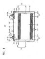
- FIG. 1 is a perspective view of a secondary battery 100 according to an embodiment of the present invention.
- FIG. 2 is a cross-sectional view taken along a line II-II of the secondary battery 100 illustrated in FIG. 1 .
- the secondary battery 100 includes an electrode assembly 10; first and second electrode terminals 21 and 22; a cap plate 30; a case 40; first and second current collectors 50 and 60; a fuse 70; and an insulating unit 80.
- the secondary battery 100 is a rectangular lithium (Li)-ion secondary battery.
- the electrode assembly 10 includes a first electrode plate 11, a separator 13 and a second electrode plate 12.
- the first and second current collectors 50 and 60 are electrically connected to the electrode assembly 10.
- the first and second current collectors 50 and 60 may be respectively and electrically connected to the first and second electrode plates 11 and 12.
- the cap plate 30 may be combined with an open surface of the case 40 so as to seal the case 40 in which the electrode assembly 10 is accommodated.
- the fuse 70 operates when an overcurrent flows due to overcharging or an abnormal phenomenon, so as to cut off the current flow.
- the insulating unit 80 wraps and fully encloses the fuse 70 with an insulating material so as to electrically block the fuse 70 from any external contact.
- the electrode assembly 10 may be formed by winding the first electrode plate 11, the separator 13 and the second electrode plate 12 in the form of a jelly roll. However, the current embodiment is not limited thereto and the electrode assembly 10 may be formed by alternately stacking the first electrode plate 11, the separator 13 and the second electrode plate 12.
- the first current collector 50 may contact the first electrode plate 11 that is exposed at one end of the electrode assembly 10. Also, the second current collector 60 may contact the second electrode plate 12 that is exposed at another end of the electrode assembly 10.
- the first electrode terminal 21 may be electrically connected to the first current collector 50 and may be partially exposed outward through the cap plate 30.
- the second electrode terminal 22 may be electrically connected to the second current collector 60 and may be partially exposed outward through the cap plate 30.
- the first electrode plate 11 may be a positive electrode plate and the second electrode plate 12 may be a negative electrode plate.
- the first current collector 50 may be a positive electrode current collector and the second current collector 60 may be a negative electrode current collector.
- the first electrode terminal 21 may be a positive electrode terminal and the second electrode terminal 22 may be a negative electrode terminal.
- the electrode assembly 10 is formed by winding the first and second electrode plates 11 and 12, and interposing the separator 13, which is an insulator, between the first and second electrode plates 11 and 12.
- the case 40 accommodates the electrode assembly 10.
- the first and second electrode terminals 21 and 22 may respectively be positive and negative electrode terminals.
- the first and second electrode terminals 21 and 22 may be electrically connected to the first and second electrode plates 11 and 12 of the electrode assembly 10, respectively, so as to be exposed to the outside of the case 40.
- the cap plate 30 is combined with an opening of the case 40.
- the fuse 70 is a device for protecting a circuit by cutting off an overcurrent that is above a preset value.
- the overcurrent may be interrupted from flowing through a circuit as the fuse 70 is melted and cut due to heat generated in response to the over current. As such, the stability of a battery may be ensured.
- first electrode plate 11, the first current collector 50, the first electrode terminal 21, the second electrode terminal 22, the second current collector 60 and the second electrode plate 12 may be electrically connected to form a circuit.
- electricity may be charged between the first and second electrode plates 11 and 12.
- the overcurrent may flow through a circuit from the first electrode plate 11 to the second electrode plate 12.
- the load on the electrode assembly 10 including the first and second electrode plates 11 and 12 may be excessive and thus an abnormal phenomenon such as an explosion may occur.
- the fuse 70 cuts off the overcurrent from flowing through a circuit, the abnormal phenomenon such as an explosion of the secondary battery 100 due to the overcurrent may be prevented. As such, the stability and reliability of the secondary battery 100 against an abnormal phenomenon due to the overcurrent may be ensured.
- the electrode assembly 10 includes the first and second electrode plates 11 and 12, and the separator 13.
- the first and second electrode plates 11 and 12, and the separator 13 that is an insulator interposed between the first and second electrode plates 11 and 12 are wound to form the electrode assembly 10.
- the first and second electrode plates 11 and 12 may respectively include first and second uncoated parts 11 a and 12a and first and second coated parts 11 b and 12b.
- the first and second uncoated parts 11 a and 12a are regions where an active material is not coated on a current collector formed of metal foil.
- the first and second coated parts 11 b and 12b are regions where an active material is coated on a current collector formed of metal foil.
- the first and second uncoated parts 11 a and 12a may respectively be positive and negative electrode uncoated parts, and the first and second coated parts 11 band 12b may respectively be positive and negative electrode coated parts.
- the first uncoated part 11 a is formed at a side end of the first electrode plate 11 in a lengthwise direction of the first electrode plate 11.
- the second uncoated part 12a is formed at another side end of the second electrode plate 12 in a lengthwise direction of the second electrode plate 12.
- the electrode assembly 10 may be formed by circularly winding and pressing the first and second electrode plates 11 and 12, and the separator 13. In this case, the electrode assembly 10 may be pressed in the form of a plate so as to form planar parts 18 and curved parts 19 as illustrated in FIG. 3 .
- the planar parts 18 are portions where the outer circumference of the electrode assembly 10 is planar when the first and second electrode plates 11 and 12, and the separator 13 are wound and pressed in the form of a plate.
- the curved parts 19 are portions where the outer circumference of the electrode assembly 10 is curved at two ends of the planar parts 18.
- the case 40 may have a shape of a rectangular can of which one surface is open. Through the open surface of the case 40, the electrode assembly 10 may be accommodated in the case 40 together with an electrolyte.
- the cap plate 30 exposes the first and second electrode terminals 21 and 22 and covers the case 40.
- the boundary between the case 40 and the cap plate 30 may be laser-welded such that the case 40 in which the electrode assembly 10 is accommodated together with the electrolyte may be sealed.
- the cap plate 30 may be a thin plate.
- An electrolyte inlet 38a through which the electrolyte is injected may be formed in the cap plate 30. After the electrolyte is injected through the electrolyte inlet 38a, a sealing plug 38 may fit in the electrolyte inlet 38a. Also, a vent member 39 in which grooves are formed may be formed in the cap plate 30 so as to be broken according to a set internal pressure.
- First and second terminal holes 21 a and 22a may be formed in the cap plate 30.
- the first and second terminal holes 21 a and 22a may respectively be positive and negative electrode terminal holes.
- the first electrode terminal 21 may be exposed through the first terminal hole 21 a and the second electrode terminal 22 may be exposed through the second terminal hole 22a.
- Upper and lower gaskets 25 and 27 may be respectively interposed between the cap plate 30 and the first and second electrode terminals 21 and 22 so as to insulate the cap plate 30 from the first and second electrode terminals 21 and 22.
- the lower gaskets 27 fit in the first and second terminal holes 21 a and 22a under the cap plate 30 and the upper gaskets 25 fit in the first and second terminal holes 21 a and 22a on the cap plate 30.
- Washers 24 for buffering a combining force are formed on the upper gaskets 25.
- Threads may be formed on the first and second electrode terminals 21 and 22 and may be combined with nuts 29. The nuts 29 support the first and second electrode terminals 21 and 22 on the case 40.
- the current embodiment is not limited thereto and the first and second electrode terminals 21 and 22 may be formed in the form of rivets.
- the first and second electrode terminals 21 and 22 may be fixed to the cap plate 30 by protruding portions of the first and second electrode terminals 21 and 22 out of the case 40 through the first and second terminal holes 21a and 22a, fitting the upper gaskets 25 between the first and second terminal holes 21 a and 22a and the protruding portions of the first and second electrode terminals 21 and 22, and pressing and spreading the protruding portions of the first and second electrode terminals 21 and 22.
- the first current collector 50 includes a first current collecting plate 51 and a first lead member 52.
- the second current collector 60 includes a second current collecting plate 61 and a second lead member 62.
- the first and second current collecting plates 51 and 61 may respectively be positive and negative electrode current collecting plates
- the first and second lead members 52 and 62 may respectively be positive and negative electrode lead members.
- the first current collecting plate 51 may be bonded to the first uncoated part 11 a of the electrode assembly 10 by using a welding method.
- the first current collecting plate 51 is electrically connected to the first electrode terminal 21 via the first lead member 52.
- the first electrode terminal 21 is connected to the first electrode plate 11 of the electrode assembly 10 via the first lead member 52 and the first current collecting plate 51.
- the second current collecting plate 61 may be bonded to the second uncoated part 12a of the electrode assembly 10 by using a welding method.
- the second current collecting plate 61 is electrically connected to the second electrode terminal 22 via the second lead member 62.
- the second electrode terminal 22 is connected to the second electrode plate 12 of the electrode assembly 10 via the second lead member 62 and the second current collecting plate 61.
- Insulating members 26 are formed between the cap plate 30 and the first and second lead members 52 and 62.
- the first and second lead members 52 and 62 respectively include first and second terminal lead units 52a and 62a, and first and second current collecting lead units 52b and 62b.
- the first and second terminal lead units 52a and 62a are bonded and electrically connected to the first and second electrode terminals 21 and 22.
- the first and second current collecting plates 51 and 61 are bonded and electrically connected to the first and second current collecting lead units 52b and 62b.
- the upper gasket 25, the insulating member 26 and the lower gasket 27 for electrically separating the first electrode plate 11 or the second electrode plate 12 from the cap plate 30 may not be formed.
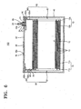
- the cap plate 30' and/or case 40 may be the first electrode terminal or the second electrode terminal.
- the upper gasket 25 and the lower gasket 27 may not be formed between the cap plate 30' and the first lead member 52 as shown in figure 6 .
- the first lead member 52 contacts the cap plate 30' directly.
- the structure and placement of the fuse 70 and the insulating unit 80 is the same as the one in Fig. 2 , therefore further description is avoided here and one is rather referred to the description of Fig. 2 .
- first electrode terminal 21 may directly contact the cap plate 30 through the first terminal hole 21 a without the upper gasket 25 and the lower gasket 27.
- first lead member 52 may directly contact the cap plate 30.
- the cap plate 30 and the case 40 have the same polarity as the first electrode terminal 21.
- the secondary battery 100 may be a Li-ion secondary battery.
- the current embodiment is not limited thereto and, in addition to the Li-ion secondary battery, the secondary battery 100 may be various other type secondary batteries such as a nickel (Ni)-cadmium (Cd) secondary battery, a nickel-hydrogen (H) secondary battery and a Li secondary battery.
- Ni nickel
- Cd nickel-cadmium
- H nickel-hydrogen
- the secondary battery 100 may be a rectangular battery as illustrated in FIGS. 1 and 2 .
- the current embodiment is not limited thereto and the secondary battery 100 may be various other type batteries such as a cylindrical battery and a pouch battery.
- the first electrode plate 11, the first current collecting plate 51 and the first lead member 52 which are electrically connected to each other may be formed of the same material, for example, aluminum (Al).
- the second electrode plate 12, the second current collecting plate 61 and the second lead member 62, which are electrically connected to each other may be formed of the same material, for example, copper (Cu).
- the fuse 70 may be formed in the first and second current collectors 50 and 60.
- the fuse 70 may be formed by making a portion of the first and second current collectors 50 and 60 thinner than the other portions. In this case, if an overcurrent flows through the first and second current collectors 50 and 60, the resistance of the fuse 70 may be increased in comparison to the other portions so as to increase Joule heat and thus the fuse 70 may be melted and cut due to the heat.
- the secondary battery 100 may include the fuse 70 and may have a simple structure. Meanwhile, the fuse 70 may be formed in at least one of the first and second current collectors 50 and 60.
- the fuse 70 may be formed in the first lead member 52 of the first current collector 50 or the second lead member 62 of the second current collector 60.
- the fuse 70 may be formed in the first current collector 50.
- the fuse 70 may be formed of Al having a melting point lower than that of Cu and thus the performance of the fuse 70 may be improved.
- the fuse 70 may be formed in the first lead member 52 in order to simplify the structure for forming the fuse 70. Also, the fuse 70 may be formed in one of the first and second current collecting lead units 52b and 62b in order to easily ensure a space for the fuse 70 and the insulating unit 80.
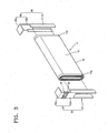
- FIG. 3 is a partial exploded perspective view showing that the first lead member 52 including the first current collecting lead unit 52b, in which the fuse 70 is formed, is separated from the electrode assembly 10 in the secondary battery 100 illustrated in FIG. 1 .
- the fuse 70 may be formed in the first current collecting lead unit 52b.
- the fuse 70 may be formed of Al having a melting point lower than that of Cu and thus the performance of the fuse 70 may be improved.
- the current embodiment is not limited thereto and the fuse 70 may be formed in the second current collecting lead unit 62b.
- the electrolyte having a form of liquid or gel may be filled in the case 40 that accommodates the electrode assembly 10.
- the first current collector 50 in which the fuse 70 is formed may contact the electrolyte.
- a spark may be generated. As such, the spark may react with the electrolyte and thus an explosion may occur.
- the secondary battery 100 may include the insulating unit 80.
- the insulating unit 80 may prevent the fuse 70 from contacting the electrolyte.
- the insulating unit 80 may wrap the fuse 70 with an insulating material so as to block the fuse 70 from the electrolyte.
- the insulating unit 80 may be insulating tape or an insulating molding.
- the fuse 70 may be electrically blocked from external contact and the structure of the secondary battery 100 may be simplified.
- the fuse 70 and the insulating unit 80 may be simply formed and the fuse 70 may protect the secondary battery 100 from an abnormal phenomenon such as overcharging. Also, as the insulating unit 80 blocks the fuse 70 from the electrolyte and thus the secondary battery 100 is prevented from exploding or igniting even when the fuse 70 operates, the stability and reliability of the secondary battery 100 may be ensured.
- the electrode assembly 10 may be wound and then pressed flat in the form of a plate, and may have an internal space 14 therein.
- the first and second current collecting plates 51 and 61 may be welded to outside ends of the electrode assembly 10 by pressing the first and second uncoated parts 11 a and 12a.
- the first and second current collecting plates 51 and 61 may respectively contact the first and second uncoated parts 11 a and 12a over large areas. Also, the first and second current collecting plates 51 and 61 may be bonded to the outside end of the electrode assembly 10 by using a laser welding method. If the first and second current collecting plates 51 and 61 are bonded by using a laser welding method, the first and second current collecting plates 51 and 61 may have a greater thickness in comparison to an ultrasonic welding method and thus the resistance of the first and second current collecting plates 51 and 61 may be reduced.
- the secondary battery 100 may be prevented from exploding even when the overcurrent flows due to overcharge or an abnormal phenomenon.
- FIG. 4 is a cross-sectional view of a secondary battery 200 according to another embodiment of the present invention.
- FIG. 5 is a partial exploded perspective view showing that a first lead member 252 including a first terminal lead unit 252a, in which a fuse 270 is formed, is separated from an electrode assembly 210 in the secondary battery 200 illustrated in FIG. 4 .
- the fuse 270 is formed in the first terminal lead unit 252a. Repeated descriptions of the secondary batteries 100 and 200 will not be provided here.
- the secondary battery 200 includes the electrode assembly 210; first and second electrode terminals 221 and 222; a cap plate 230; a case 240; first and second current collectors 250 and 260; the fuse 270; and an insulating unit 280.
- the electrode assembly 210 is formed by winding first and second electrode plates 211 and 212 that may respectively be positive and negative electrode plates, and a separator 213 that is an insulator interposed between the first and second electrode plates 211 and 212.
- the case 240 accommodates the electrode assembly 210.
- the first and second electrode terminals 221 and 222 may respectively be positive and negative electrode terminals.
- the first and second electrode terminals 221 and 222 may be respectively and electrically connected to the first and second electrode plates 211 and 212 of the electrode assembly 210 so as to be exposed outside the case 240.
- the cap plate 230 is combined with an opening of the case 240.
- the first and second current collectors 250 and 260 may respectively be positive and negative electrode current collectors that are electrically connected to the first and second electrode plates 211 and 212.
- the fuse 270 operates when an overcurrent flows due to overcharging or an abnormal phenomenon, so as to cut off the current flow.
- the insulating unit 280 wraps the fuse 270 with an insulating material so as to electrically block the fuse 270 from any external contact.
- the first electrode plate 211 includes a first uncoated part 211 a and a first coated part 211 b.
- the second electrode plate 212 includes a second uncoated part 212a and a second coated part 212b.
- the first and second uncoated parts 211 a and 212a may respectively be positive and negative electrode uncoated parts, and the first and second coated parts 211 b and 212b may respectively be positive and negative electrode coated parts.
- the first electrode terminal 221 may be exposed through a first terminal hole 221 a that is a positive electrode terminal hole, and the second electrode terminal 222 may be exposed through a second terminal hole 222a that is a negative electrode terminal hole.
- An electrolyte inlet 238a may be formed in the cap plate 230, a sealing plug 238 may fit in the electrolyte inlet 238a, and a vent member 239 may also be formed in the cap plate 230.
- Upper and lower gaskets 225 and 227 may be respectively interposed between the cap plate 230 and the first and second electrode terminals 221 and 222 so as to insulate the cap plate 230 from the first and second electrode terminals 221 and 222.
- Washers 224 for buffering a combining force are formed on the upper gaskets 225.
- the first and second electrode terminals 221 and 222 may be combined with nuts 229. Alternatively, the first and second electrode terminals 221 and 222 may be formed in the form of rivets.
- First and second current collecting plates 251 and 261 may be respectively bonded to the first and second uncoated parts 211 a and 212a of the electrode assembly 210 by using a welding method.
- the first and second current collecting plates 251 and 261 are respectively and electrically connected to the first and second electrode terminal 221 and 222 via first and second lead members 252 and 262.
- Insulating members 226 are formed between the cap plate 230 and the first and second lead members 252 and 262.
- the first and second lead members 252 and 262 respectively include first and second terminal lead units 252a and 262a, and first and second current collecting lead units 252b and 262b.
- the first and second terminal lead units 252a and 262a are bonded and electrically connected to the first and second electrode terminals 221 and 222.
- the first and second current collecting lead units 252b and 262b are bonded and electrically connected to the first and second current collecting plates 251 and 261.
- the first current collector 250 includes the first current collecting plate 251 and the first lead member 252, and the second current collector 260 includes the second current collecting plate 261 and the second lead member 262.
- the first and second current collecting plates 251 and 261 may respectively be positive and negative electrode current collecting plates, and the first and second lead members 252 and 262 may respectively be positive and negative electrode lead members.
- the first current collecting plate 251 may be bonded to the first uncoated part 211 a of the electrode assembly 210 by using a welding method.
- the first current collecting plate 251 is electrically connected to the first electrode terminal 221 via the first lead member 252.
- the first electrode terminal 221 is connected to the first electrode plate 211 of the electrode assembly 210 via the first lead member 252 and the first current collecting plate 251.
- the second current collecting plate 261 may be bonded to the second uncoated part 212a of the electrode assembly 210 by using a welding method.
- the second current collecting plate 261 is electrically connected to the second electrode terminal 222 via the second lead member 262.
- the second electrode terminal 222 is connected to the second electrode plate 212 of the electrode assembly 210 via the second lead member 262 and the second current collecting plate 261.
- the upper gasket 225, the insulating member 226 and the lower gasket 227 for electrically separating the first electrode plate 211 or the second electrode plate 212 from the cap plate 230 may not be formed.
- the cap plate 230' and/or case 240 may be the first electrode terminal or the second electrode terminal.
- the upper gasket 225 and the lower gasket 227 may not be formed between the cap plate 230' and the first lead member 252 as shown in figure 7 .
- the first lead member 252 contacts the cap plate 230' directly.
- the structure and placement of the fuse 270 and the insulating unit 280 is the same as the one in Fig. 4 , therefore further description is avoided here and one is rather referred to the description of Fig. 4 .
- the secondary battery 200 may include the fuse 270 and may have a simple structure. Meanwhile, the fuse 270 may be formed in at least one of the first and second current collectors 250 and 260.
- the fuse 270 may be formed in the first lead member 252 of the first current collector 250 or the second lead member 262 of the second current collector 260.
- the fuse 270 may be formed in the first current collector 250.
- the fuse 270 may be formed of Al having a melting point lower than that of Cu and thus the performance of the fuse 270 may be increased.
- the fuse 270 may be formed in the first lead member 252 in order to further simplify the structure for forming the fuse 270. Also, the fuse 270 may be formed in one of the first and second terminal lead units 252a and 262a in order to easily ensure a space for the fuse 270 and the insulating unit 280.
- the fuse 270 may be formed in the first terminal lead unit 252a.
- the fuse 70 may be formed of Al having a melting point lower than that of Cu and thus the performance of the fuse 270 may be improved.
- an electrolyte in the form of liquid or gel may be filled in the case 240 that accommodates the electrode assembly 210.
- the first current collector 250 in which the fuse 270 is formed may contact the electrolyte.
- a spark may be generated. As such, the spark may react with the electrolyte and thus an explosion may occur.
- the secondary battery 200 may include the insulating unit 280.
- the insulating unit 280 may prevent the fuse 270 from contacting the electrolyte.
- the insulating unit 280 may wrap the fuse 270 with an insulating material so as to block the fuse 270 from the electrolyte.
- the insulating unit 280 may be insulating tape or an insulating molding.
- the fuse 270 may be electrically blocked from any external contact and the structure of the secondary battery 200 may be simplified.
- the fuse 270 and the insulating unit 280 may be simply formed and the fuse 270 may protect the secondary battery 200 from an abnormal phenomenon such as overcharging. Also, as the insulating unit 280 blocks the fuse 270 from the electrolyte and thus the secondary battery 200 is prevented from exploding or igniting even when the fuse 270 operates, the stability and reliability of the secondary battery 200 may be ensured.
- the secondary battery 200 may be prevented from exploding even when an overcurrent flows due to overcharging or an abnormal phenomenon.
Description
- One or more embodiments of the present invention relate to a secondary battery, and more particularly, to a secondary battery protected by operating a fuse when an overcurrent flows due to overcharging or an abnormal phenomenon.
- Unlike primary batteries that are not rechargeable, secondary batteries are rechargeable batteries. Secondary batteries are broadly used in high-tech electronic devices such as cellular phones, notebook computers and camcorders and also are used in vehicles.
- A secondary battery includes an electrode assembly and an electrolyte. The electrode assembly includes positive and negative electrode plates and a separator. The electrolyte includes lithium (Li) ions in many cases. The positive and negative electrode plates of the electrode assembly may include electrode tabs protruding outward.
- The electrode assembly may be accommodated in a case and electrode terminals may be exposed outside the case. The electrode tabs may protrude outside the electrode assembly so as to be electrically connected to the electrode terminals. The case may have a cylindrical shape or a rectangular shape.
- Document
US 2004/0170887 A1 discloses a secondary battery having a thermal fuse welded to an electrode lead. DocumentEP 2 348 558 A1 discloses a secondary battery having a fuse element inside its case, the fuse comprising a fuse opening and reinforcement protrusions. - One or more embodiments of the present invention include a secondary battery capable of preventing an explosion even when an overcurrent flows due to overcharging or an abnormal phenomenon.
- According to one or more embodiments of the present invention, a secondary battery includes: an electrode assembly having a first electrode plate, a second electrode plate, and a separator interposed between the first and the second electrodes plates, and a case for mounting the electrode assembly therein. Further provided is a first electrode terminal, and a fuse portion provided inside the case, wherein the first electrode terminal is electrically connected to the first electrode plate via the fuse portion. The fuse portion is formed by an opening in the connection of the first electrode terminal and the first electrode plate. An insulating unit is provided fully enclosing the fuse portion.
- Advantageously, the insulating unit electrically blocks the fuse from its environment.
- Preferably, the surface of the insulating unit is larger and covers the surface of the fuse portion.
- The insulating unit is provided such that a contact of the fuse portion with an electrolyte inside the case is prevented.
- Advantageously, the insulating unit blocks the fuse from contacting the electrolyte and thus prevents explosion of the battery.
- The insulating unit may comprise an insulating tape or an insulating molding.
- Preferably, the fuse portion is adapted to disconnect the first electrode plate from the first electrode terminal when a current flowing between the first electrode plate and the first electrode terminal exceeds a set threshold value.
- A first current collector may be further provided to electrically connect the first electrode plate with the first electrode terminal, wherein the first current collector integrally comprises the fuse portion. Preferably, the fuse portion has a smaller cross-section area than other parts of the first current collector. The fuse portion may have a higher electrical resistance than other parts of the first current collector. The fuse portion may be formed of a material having a lower melting point than other parts of the first current collector.
- In one embodiment, the first current collector comprises a first current collecting plate coupled to the first electrode plate, and a first lead member coupled to the first electrode terminal and the current collecting plate, the first lead member comprising the fuse portion.
- In another embodiment, the first lead member comprises a first terminal lead unit coupled to the first electrode terminal, and a current collecting lead unit bent from the first terminal lead unit and coupled the current collecting plate, wherein the first terminal lead unit comprises the fuse portion, or the current collecting lead unit comprises the fuse portion.
- The secondary battery may further comprise a second electrode terminal electrically connected to the second electrode plate, a second current collector electrically coupled between the second electrode plate and the second electrode terminal, wherein the first electrode plate is a positive electrode plate and the first current collector is a positive current collector, and the second electrode plate is a negative electrode plate and the second current collector is a negative current collector.
- The first terminal may be a cap plate, or the case of the battery, or an external terminal protruding through a cap plate.
- A secondary battery according to one or more embodiments of the present invention may prevent an explosion even when an overcurrent flows due to overcharging or an abnormal phenomenon.
-
-
FIG. 1 is a perspective view of a secondary battery according to an embodiment of the present invention. -
FIG. 2 is a cross-sectional view taken along a line II-II of the secondary battery illustrated inFIG. 1 . -
FIG. 3 is a partial exploded perspective view showing that a lead member including a current collecting lead unit in which a fuse is formed is separated from an electrode assembly in the secondary battery illustrated inFIG. 1 . -
FIG. 4 is a cross-sectional view of a secondary battery according to another embodiment of the present invention. -
FIG. 5 is a partial exploded perspective view showing that a lead member including a terminal lead unit in which a fuse is formed is separated from an electrode assembly in the secondary battery illustrated inFIG. 4 . -
FIG. 6 is a drawing of a secondary battery corresponding to to the embodiment ofFig. 2 but in which the first lead member contacts the cap plate directly. -
FIG. 7 is a drawing of a secondary battery corresponding to the embodiment ofFig. 4 but in which the first lead member contacts the cap plate directly. - Reference will now be made in detail to embodiments, examples of which are illustrated in the accompanying drawings.
-
FIG. 1 is a perspective view of asecondary battery 100 according to an embodiment of the present invention.FIG. 2 is a cross-sectional view taken along a line II-II of thesecondary battery 100 illustrated inFIG. 1 . - Referring to
FIGS. 1 and2 , thesecondary battery 100 includes anelectrode assembly 10; first andsecond electrode terminals cap plate 30; acase 40; first and secondcurrent collectors fuse 70; and aninsulating unit 80. Here, it is exemplarily but not restrictingly assumed that thesecondary battery 100 is a rectangular lithium (Li)-ion secondary battery. - The
electrode assembly 10 includes afirst electrode plate 11, aseparator 13 and asecond electrode plate 12. The first and secondcurrent collectors electrode assembly 10. The first and secondcurrent collectors second electrode plates cap plate 30 may be combined with an open surface of thecase 40 so as to seal thecase 40 in which theelectrode assembly 10 is accommodated. - The
fuse 70 operates when an overcurrent flows due to overcharging or an abnormal phenomenon, so as to cut off the current flow. Theinsulating unit 80 wraps and fully encloses thefuse 70 with an insulating material so as to electrically block thefuse 70 from any external contact. - The
electrode assembly 10 may be formed by winding thefirst electrode plate 11, theseparator 13 and thesecond electrode plate 12 in the form of a jelly roll. However, the current embodiment is not limited thereto and theelectrode assembly 10 may be formed by alternately stacking thefirst electrode plate 11, theseparator 13 and thesecond electrode plate 12. - The first
current collector 50 may contact thefirst electrode plate 11 that is exposed at one end of theelectrode assembly 10. Also, the secondcurrent collector 60 may contact thesecond electrode plate 12 that is exposed at another end of theelectrode assembly 10. - The
first electrode terminal 21 may be electrically connected to the firstcurrent collector 50 and may be partially exposed outward through thecap plate 30. Thesecond electrode terminal 22 may be electrically connected to the secondcurrent collector 60 and may be partially exposed outward through thecap plate 30. - In the
secondary battery 100, thefirst electrode plate 11 may be a positive electrode plate and thesecond electrode plate 12 may be a negative electrode plate. Also, the firstcurrent collector 50 may be a positive electrode current collector and the secondcurrent collector 60 may be a negative electrode current collector. Also, thefirst electrode terminal 21 may be a positive electrode terminal and thesecond electrode terminal 22 may be a negative electrode terminal. - The
electrode assembly 10 is formed by winding the first andsecond electrode plates separator 13, which is an insulator, between the first andsecond electrode plates case 40 accommodates theelectrode assembly 10. The first andsecond electrode terminals second electrode terminals second electrode plates electrode assembly 10, respectively, so as to be exposed to the outside of thecase 40. Thecap plate 30 is combined with an opening of thecase 40. - The
fuse 70 is a device for protecting a circuit by cutting off an overcurrent that is above a preset value. When the overcurrent flows, the overcurrent may be interrupted from flowing through a circuit as thefuse 70 is melted and cut due to heat generated in response to the over current. As such, the stability of a battery may be ensured. - Meanwhile, the
first electrode plate 11, the firstcurrent collector 50, thefirst electrode terminal 21, thesecond electrode terminal 22, the secondcurrent collector 60 and thesecond electrode plate 12 may be electrically connected to form a circuit. Here, if power is input from an external device through the first andsecond electrode terminal second electrode plates - In this case, due to overcharging or another abnormal phenomenon, the overcurrent may flow through a circuit from the
first electrode plate 11 to thesecond electrode plate 12. When the overcurrent flows through a circuit, the load on theelectrode assembly 10 including the first andsecond electrode plates - However, as the
fuse 70 cuts off the overcurrent from flowing through a circuit, the abnormal phenomenon such as an explosion of thesecondary battery 100 due to the overcurrent may be prevented. As such, the stability and reliability of thesecondary battery 100 against an abnormal phenomenon due to the overcurrent may be ensured. - The
electrode assembly 10 includes the first andsecond electrode plates separator 13. In this case, the first andsecond electrode plates separator 13 that is an insulator interposed between the first andsecond electrode plates electrode assembly 10. - The first and
second electrode plates uncoated parts coated parts uncoated parts coated parts uncoated parts coated parts 11band 12b may respectively be positive and negative electrode coated parts. - The first
uncoated part 11 a is formed at a side end of thefirst electrode plate 11 in a lengthwise direction of thefirst electrode plate 11. The seconduncoated part 12a is formed at another side end of thesecond electrode plate 12 in a lengthwise direction of thesecond electrode plate 12. - Meanwhile, the
electrode assembly 10 may be formed by circularly winding and pressing the first andsecond electrode plates separator 13. In this case, theelectrode assembly 10 may be pressed in the form of a plate so as to formplanar parts 18 andcurved parts 19 as illustrated inFIG. 3 . - The
planar parts 18 are portions where the outer circumference of theelectrode assembly 10 is planar when the first andsecond electrode plates separator 13 are wound and pressed in the form of a plate. Thecurved parts 19 are portions where the outer circumference of theelectrode assembly 10 is curved at two ends of theplanar parts 18. - The
case 40 may have a shape of a rectangular can of which one surface is open. Through the open surface of thecase 40, theelectrode assembly 10 may be accommodated in thecase 40 together with an electrolyte. Thecap plate 30 exposes the first andsecond electrode terminals case 40. The boundary between thecase 40 and thecap plate 30 may be laser-welded such that thecase 40 in which theelectrode assembly 10 is accommodated together with the electrolyte may be sealed. - The
cap plate 30 may be a thin plate. Anelectrolyte inlet 38a through which the electrolyte is injected may be formed in thecap plate 30. After the electrolyte is injected through theelectrolyte inlet 38a, a sealingplug 38 may fit in theelectrolyte inlet 38a. Also, avent member 39 in which grooves are formed may be formed in thecap plate 30 so as to be broken according to a set internal pressure. - First and second terminal holes 21 a and 22a may be formed in the
cap plate 30. The first and second terminal holes 21 a and 22a may respectively be positive and negative electrode terminal holes. Thefirst electrode terminal 21 may be exposed through the firstterminal hole 21 a and thesecond electrode terminal 22 may be exposed through the secondterminal hole 22a. - Upper and
lower gaskets cap plate 30 and the first andsecond electrode terminals cap plate 30 from the first andsecond electrode terminals - The
lower gaskets 27 fit in the first and second terminal holes 21 a and 22a under thecap plate 30 and theupper gaskets 25 fit in the first and second terminal holes 21 a and 22a on thecap plate 30.Washers 24 for buffering a combining force are formed on theupper gaskets 25. Threads may be formed on the first andsecond electrode terminals second electrode terminals case 40. - However, the current embodiment is not limited thereto and the first and
second electrode terminals second electrode terminals cap plate 30 by protruding portions of the first andsecond electrode terminals case 40 through the first and secondterminal holes upper gaskets 25 between the first and second terminal holes 21 a and 22a and the protruding portions of the first andsecond electrode terminals second electrode terminals - The first
current collector 50 includes a first current collectingplate 51 and afirst lead member 52. The secondcurrent collector 60 includes a second current collectingplate 61 and asecond lead member 62. Here, the first and second current collectingplates second lead members - The first current collecting
plate 51 may be bonded to the firstuncoated part 11 a of theelectrode assembly 10 by using a welding method. The first current collectingplate 51 is electrically connected to thefirst electrode terminal 21 via thefirst lead member 52. As such, thefirst electrode terminal 21 is connected to thefirst electrode plate 11 of theelectrode assembly 10 via thefirst lead member 52 and the first current collectingplate 51. - Also, the second current collecting
plate 61 may be bonded to the seconduncoated part 12a of theelectrode assembly 10 by using a welding method. The second current collectingplate 61 is electrically connected to thesecond electrode terminal 22 via thesecond lead member 62. As such, thesecond electrode terminal 22 is connected to thesecond electrode plate 12 of theelectrode assembly 10 via thesecond lead member 62 and the second current collectingplate 61. - Insulating
members 26 are formed between thecap plate 30 and the first andsecond lead members second lead members terminal lead units lead units terminal lead units second electrode terminals plates lead units - According to another embodiment of the present invention, with respect to one of the first and
second electrode terminals upper gasket 25, the insulatingmember 26 and thelower gasket 27 for electrically separating thefirst electrode plate 11 or thesecond electrode plate 12 from thecap plate 30 may not be formed. In this case, the cap plate 30' and/orcase 40 may be the first electrode terminal or the second electrode terminal. - For example, the
upper gasket 25 and thelower gasket 27 may not be formed between the cap plate 30' and thefirst lead member 52 as shown infigure 6 . In this case, thefirst lead member 52 contacts the cap plate 30' directly. The structure and placement of thefuse 70 and the insulatingunit 80 is the same as the one inFig. 2 , therefore further description is avoided here and one is rather referred to the description ofFig. 2 . - Thus the
first electrode terminal 21 may directly contact thecap plate 30 through the firstterminal hole 21 a without theupper gasket 25 and thelower gasket 27. Also, thefirst lead member 52 may directly contact thecap plate 30. In this case, thecap plate 30 and thecase 40 have the same polarity as thefirst electrode terminal 21. - The
secondary battery 100 may be a Li-ion secondary battery. However, the current embodiment is not limited thereto and, in addition to the Li-ion secondary battery, thesecondary battery 100 may be various other type secondary batteries such as a nickel (Ni)-cadmium (Cd) secondary battery, a nickel-hydrogen (H) secondary battery and a Li secondary battery. - The
secondary battery 100 may be a rectangular battery as illustrated inFIGS. 1 and2 . However, the current embodiment is not limited thereto and thesecondary battery 100 may be various other type batteries such as a cylindrical battery and a pouch battery. - The
first electrode plate 11, the first current collectingplate 51 and thefirst lead member 52 which are electrically connected to each other may be formed of the same material, for example, aluminum (Al). Also, thesecond electrode plate 12, the second current collectingplate 61 and thesecond lead member 62, which are electrically connected to each other may be formed of the same material, for example, copper (Cu). - The
fuse 70 may be formed in the first and secondcurrent collectors fuse 70 may be formed by making a portion of the first and secondcurrent collectors current collectors fuse 70 may be increased in comparison to the other portions so as to increase Joule heat and thus thefuse 70 may be melted and cut due to the heat. - As the
fuse 70 may be formed in one of the first and secondcurrent collectors secondary battery 100 may include thefuse 70 and may have a simple structure. Meanwhile, thefuse 70 may be formed in at least one of the first and secondcurrent collectors - The
fuse 70 may be formed in thefirst lead member 52 of the firstcurrent collector 50 or thesecond lead member 62 of the secondcurrent collector 60. For example, thefuse 70 may be formed in the firstcurrent collector 50. In this case, thefuse 70 may be formed of Al having a melting point lower than that of Cu and thus the performance of thefuse 70 may be improved. - In this case, the
fuse 70 may be formed in thefirst lead member 52 in order to simplify the structure for forming thefuse 70. Also, thefuse 70 may be formed in one of the first and second current collectinglead units fuse 70 and the insulatingunit 80.FIG. 3 is a partial exploded perspective view showing that thefirst lead member 52 including the first current collectinglead unit 52b, in which thefuse 70 is formed, is separated from theelectrode assembly 10 in thesecondary battery 100 illustrated inFIG. 1 . - In
FIG. 3 , thefuse 70 may be formed in the first current collectinglead unit 52b. In this case, thefuse 70 may be formed of Al having a melting point lower than that of Cu and thus the performance of thefuse 70 may be improved. However, the current embodiment is not limited thereto and thefuse 70 may be formed in the second current collectinglead unit 62b. - Meanwhile, the electrolyte having a form of liquid or gel may be filled in the
case 40 that accommodates theelectrode assembly 10. In this case, the firstcurrent collector 50 in which thefuse 70 is formed may contact the electrolyte. Also, when thefuse 70 operates due to an overcurrent, a spark may be generated. As such, the spark may react with the electrolyte and thus an explosion may occur. - Accordingly, the
secondary battery 100 may include the insulatingunit 80. The insulatingunit 80 may prevent thefuse 70 from contacting the electrolyte. For this, the insulatingunit 80 may wrap thefuse 70 with an insulating material so as to block thefuse 70 from the electrolyte. The insulatingunit 80 may be insulating tape or an insulating molding. - As the insulating tape is taped around the
fuse 70 as an example of the insulatingunit 80, thefuse 70 may be electrically blocked from external contact and the structure of thesecondary battery 100 may be simplified. - Also, the
fuse 70 and the insulatingunit 80 may be simply formed and thefuse 70 may protect thesecondary battery 100 from an abnormal phenomenon such as overcharging. Also, as the insulatingunit 80 blocks thefuse 70 from the electrolyte and thus thesecondary battery 100 is prevented from exploding or igniting even when thefuse 70 operates, the stability and reliability of thesecondary battery 100 may be ensured. - The
electrode assembly 10 may be wound and then pressed flat in the form of a plate, and may have an internal space 14 therein. The first and second current collectingplates electrode assembly 10 by pressing the first and seconduncoated parts - As such, the first and second current collecting
plates uncoated parts plates electrode assembly 10 by using a laser welding method. If the first and second current collectingplates plates plates - As described above, the
secondary battery 100 may be prevented from exploding even when the overcurrent flows due to overcharge or an abnormal phenomenon. -
FIG. 4 is a cross-sectional view of asecondary battery 200 according to another embodiment of the present invention.FIG. 5 is a partial exploded perspective view showing that afirst lead member 252 including a firstterminal lead unit 252a, in which afuse 270 is formed, is separated from anelectrode assembly 210 in thesecondary battery 200 illustrated inFIG. 4 . - When compared to the
secondary battery 100 illustrated inFIG. 2 , in thesecondary battery 200, thefuse 270 is formed in the firstterminal lead unit 252a. Repeated descriptions of thesecondary batteries - Referring to
FIGS. 4 and5 , thesecondary battery 200 includes theelectrode assembly 210; first andsecond electrode terminals cap plate 230; acase 240; first and secondcurrent collectors fuse 270; and an insulatingunit 280. - The
electrode assembly 210 is formed by winding first andsecond electrode plates separator 213 that is an insulator interposed between the first andsecond electrode plates case 240 accommodates theelectrode assembly 210. The first andsecond electrode terminals - The first and
second electrode terminals second electrode plates electrode assembly 210 so as to be exposed outside thecase 240. Thecap plate 230 is combined with an opening of thecase 240. The first and secondcurrent collectors second electrode plates - The
fuse 270 operates when an overcurrent flows due to overcharging or an abnormal phenomenon, so as to cut off the current flow. The insulatingunit 280 wraps thefuse 270 with an insulating material so as to electrically block thefuse 270 from any external contact. - The
first electrode plate 211 includes a firstuncoated part 211 a and a firstcoated part 211 b. Thesecond electrode plate 212 includes a seconduncoated part 212a and a secondcoated part 212b. The first and seconduncoated parts coated parts first electrode terminal 221 may be exposed through a firstterminal hole 221 a that is a positive electrode terminal hole, and thesecond electrode terminal 222 may be exposed through a secondterminal hole 222a that is a negative electrode terminal hole. - An
electrolyte inlet 238a may be formed in thecap plate 230, a sealingplug 238 may fit in theelectrolyte inlet 238a, and avent member 239 may also be formed in thecap plate 230. Upper andlower gaskets cap plate 230 and the first andsecond electrode terminals cap plate 230 from the first andsecond electrode terminals Washers 224 for buffering a combining force are formed on theupper gaskets 225. The first andsecond electrode terminals second electrode terminals - First and second current collecting
plates uncoated parts electrode assembly 210 by using a welding method. The first and second current collectingplates second electrode terminal second lead members - Insulating
members 226 are formed between thecap plate 230 and the first andsecond lead members second lead members terminal lead units lead units terminal lead units second electrode terminals lead units plates - The first
current collector 250 includes the firstcurrent collecting plate 251 and thefirst lead member 252, and the secondcurrent collector 260 includes the second current collectingplate 261 and thesecond lead member 262. The first and second current collectingplates second lead members - The first
current collecting plate 251 may be bonded to the firstuncoated part 211 a of theelectrode assembly 210 by using a welding method. The firstcurrent collecting plate 251 is electrically connected to thefirst electrode terminal 221 via thefirst lead member 252. As such, thefirst electrode terminal 221 is connected to thefirst electrode plate 211 of theelectrode assembly 210 via thefirst lead member 252 and the firstcurrent collecting plate 251. - Also, the second current collecting
plate 261 may be bonded to the seconduncoated part 212a of theelectrode assembly 210 by using a welding method. The second current collectingplate 261 is electrically connected to thesecond electrode terminal 222 via thesecond lead member 262. As such, thesecond electrode terminal 222 is connected to thesecond electrode plate 212 of theelectrode assembly 210 via thesecond lead member 262 and the second current collectingplate 261. - According to another embodiment of the present invention, with respect to one of the first and
second electrode terminals upper gasket 225, the insulatingmember 226 and thelower gasket 227 for electrically separating thefirst electrode plate 211 or thesecond electrode plate 212 from thecap plate 230 may not be formed. In this case, the cap plate 230' and/orcase 240 may be the first electrode terminal or the second electrode terminal. - For example, the
upper gasket 225 and thelower gasket 227 may not be formed between the cap plate 230' and thefirst lead member 252 as shown infigure 7 . In this case, thefirst lead member 252 contacts the cap plate 230' directly. The structure and placement of thefuse 270 and the insulatingunit 280 is the same as the one inFig. 4 , therefore further description is avoided here and one is rather referred to the description ofFig. 4 . - As the
fuse 270 may be formed in one of the first and secondcurrent collectors secondary battery 200 may include thefuse 270 and may have a simple structure. Meanwhile, thefuse 270 may be formed in at least one of the first and secondcurrent collectors - The
fuse 270 may be formed in thefirst lead member 252 of the firstcurrent collector 250 or thesecond lead member 262 of the secondcurrent collector 260. For example, thefuse 270 may be formed in the firstcurrent collector 250. In this case, thefuse 270 may be formed of Al having a melting point lower than that of Cu and thus the performance of thefuse 270 may be increased. - In this case, the
fuse 270 may be formed in thefirst lead member 252 in order to further simplify the structure for forming thefuse 270. Also, thefuse 270 may be formed in one of the first and secondterminal lead units fuse 270 and the insulatingunit 280. - In
FIG. 5 , thefuse 270 may be formed in the firstterminal lead unit 252a. In this case, thefuse 70 may be formed of Al having a melting point lower than that of Cu and thus the performance of thefuse 270 may be improved. - Meanwhile, an electrolyte in the form of liquid or gel may be filled in the
case 240 that accommodates theelectrode assembly 210. In this case, the firstcurrent collector 250 in which thefuse 270 is formed may contact the electrolyte. Also, when thefuse 270 operates due to an overcurrent, a spark may be generated. As such, the spark may react with the electrolyte and thus an explosion may occur. - Accordingly, the
secondary battery 200 may include the insulatingunit 280. The insulatingunit 280 may prevent thefuse 270 from contacting the electrolyte. For this, the insulatingunit 280 may wrap thefuse 270 with an insulating material so as to block thefuse 270 from the electrolyte. The insulatingunit 280 may be insulating tape or an insulating molding. - As the insulating tape is taped around the
fuse 270 as an example of the insulatingunit 280, thefuse 270 may be electrically blocked from any external contact and the structure of thesecondary battery 200 may be simplified. - Also, the
fuse 270 and the insulatingunit 280 may be simply formed and thefuse 270 may protect thesecondary battery 200 from an abnormal phenomenon such as overcharging. Also, as the insulatingunit 280 blocks thefuse 270 from the electrolyte and thus thesecondary battery 200 is prevented from exploding or igniting even when thefuse 270 operates, the stability and reliability of thesecondary battery 200 may be ensured. - As described above, the
secondary battery 200 may be prevented from exploding even when an overcurrent flows due to overcharging or an abnormal phenomenon. - It should be understood that the exemplary embodiments described herein should be considered in a descriptive sense only and not for purposes of limitation. Descriptions of features or aspects within each embodiment should typically be considered as available for other similar features or aspects in other embodiments.
Claims (13)
- A secondary battery (100, 200) comprising:an electrode assembly (10) having a first electrode plate (11), a second electrode plate (12), and a separator (13) interposed between the first and the second electrodes plates (11, 12);a case (40) for mounting the electrode assembly (10) therein;a first electrode terminal (21, 30), anda fuse portion (70) provided inside the case (40),wherein the first electrode terminal (21, 30) is electrically connected to the first electrode plate (11) via the fuse portion (70),characterized in thatthe fuse portion (70) is formed by an opening in an electrical connection element between the first electrode terminal (21, 30) and the first electrode plate (11) and an insulating unit (80) fully encloses the fuse portion (70).
- The secondary battery (100, 200) of claim 1, wherein the surface of the insulating unit (80) is larger than the surface of the fuse portion (70) and covers the surface of the fuse portion (70).
- The secondary battery (100, 200) of any of the previous claims, wherein the insulating unit (80) is provided such that a contact of the fuse portion (70) with an electrolyte inside the case (40) is prevented.
- The secondary battery (100, 200) of any of the previous claims, wherein the insulating unit (80) comprises an insulating tape or an insulating molding.
- The secondary battery (100, 200) of any of the previous claims, wherein the fuse portion (70) is adapted to disconnect the first electrode plate (11) from the first electrode terminal (21, 30) when a current flowing between the first electrode plate (11) and the first electrode terminal (21, 30) exceeds a set threshold value.
- The secondary battery (100, 200) of any of the previous claims, further comprising a first current collector (50) to electrically connect the first electrode plate (11) with the first electrode terminal (21, 30) wherein the first current collector (50) integrally comprises the fuse portion (70).
- The secondary battery (100, 200) of claim 6, wherein the fuse portion (70) has a smaller cross-section area than other parts of the first current collector (50).
- The secondary battery (100, 200) of claim 6 or 7, wherein the fuse portion (70) has a higher electrical resistance than other parts of the first current collector (50).
- The secondary battery (100, 200) of any of claims 6 to 8, wherein the fuse portion (70) is formed of a material having a lower melting point than other parts of the first current collector (50).
- The secondary battery (100, 200) of any of claims 6 to 9, wherein the first current collector (50) comprises:a first current collecting plate (51) coupled to the first electrode plate (11); anda first lead member (52) coupled to the first electrode terminal (21, 30) and the current collecting plate (51) and comprising the fuse portion (70).
- The secondary battery (100, 200) of claim 10, wherein the first lead member (252) comprises:a first terminal lead unit (52a, 252a) coupled to the first electrode terminal (21, 30, 221, 230), anda current collecting lead unit (52b, 252b) bent from the first terminal lead unit (52a, 252a) and coupled the current collecting plate (51, 251), whereinthe first terminal lead unit (252a) comprises the fuse portion (270), orthe current collecting lead unit (52b) comprises the fuse portion (70).
- The secondary battery of any of the previous claims, wherein the secondary battery further comprises:a second electrode terminal (22) electrically connected to the second electrode plate (12),a second current collector (60) electrically coupled between the second electrode plate (12) and the second electrode terminal (22),whereinthe first electrode plate (11) is a positive electrode plate and the first current collector (50) is a positive current collector, andthe second electrode plate (12) is a negative electrode plate and the second current collector (60) is a negative current collector.
- The secondary battery of any of the previous claims 1 to 11, wherein the first terminal is:a cap plate (30), orthe case (40) of the battery, oran external terminal (21) protruding through a cap plate (30).
Applications Claiming Priority (1)
| Application Number | Priority Date | Filing Date | Title |
|---|---|---|---|
| US31911010P | 2010-03-30 | 2010-03-30 |
Publications (2)
| Publication Number | Publication Date |
|---|---|
| EP2372808A1 EP2372808A1 (en) | 2011-10-05 |
| EP2372808B1 true EP2372808B1 (en) | 2015-03-04 |
Family
ID=42813168
Family Applications (1)
| Application Number | Title | Priority Date | Filing Date |
|---|---|---|---|
| EP10169767.0A Active EP2372808B1 (en) | 2010-03-30 | 2010-07-16 | Secondary battery having a fuse |
Country Status (4)
| Country | Link |
|---|---|
| US (1) | US9059459B2 (en) |
| EP (1) | EP2372808B1 (en) |
| JP (1) | JP5517974B2 (en) |
| KR (1) | KR101130294B1 (en) |
Cited By (1)
| Publication number | Priority date | Publication date | Assignee | Title |
|---|---|---|---|---|
| CN109792029A (en) * | 2016-11-15 | 2019-05-21 | 宁德时代新能源科技股份有限公司 | Secondary cell and battery modules |
Families Citing this family (49)
| Publication number | Priority date | Publication date | Assignee | Title |
|---|---|---|---|---|
| US9246140B2 (en) * | 2009-07-09 | 2016-01-26 | Samsung Sdi Co., Ltd. | Rechargeable battery with a cap assembly having a first tab located outside of the case |
| US8877361B2 (en) * | 2009-09-01 | 2014-11-04 | Samsung Sdi Co., Ltd. | Rechargeable battery |
| US9099732B2 (en) * | 2010-06-11 | 2015-08-04 | Samsung Sdi Co., Ltd. | Rechargeable battery having a fuse with an insulating blocking member |
| KR101126809B1 (en) * | 2010-06-16 | 2012-03-23 | 에스비리모티브 주식회사 | Secondary Battery |
| US9478774B2 (en) | 2010-12-02 | 2016-10-25 | Samsung Sdi Co., Ltd. | Rechargeable battery |
| KR101222415B1 (en) | 2011-01-13 | 2013-01-14 | 로베르트 보쉬 게엠베하 | Secondary battery |
| KR101274806B1 (en) | 2011-07-26 | 2013-06-13 | 로베르트 보쉬 게엠베하 | Rechargeable battery |
| US9634299B2 (en) | 2011-09-06 | 2017-04-25 | Samsung Sdi Co., Ltd. | Rechargeable battery |
| US8940420B2 (en) * | 2011-09-29 | 2015-01-27 | Samsung Sdi Co., Ltd. | Rechargeable battery |
| US8889292B2 (en) * | 2011-10-13 | 2014-11-18 | Samsung Sdi Co., Ltd. | Rechargeable battery |
| KR101683210B1 (en) | 2011-11-17 | 2016-12-07 | 삼성에스디아이 주식회사 | Rechargeable battery |
| CN202495505U (en) * | 2011-11-25 | 2012-10-17 | 深圳市比亚迪锂电池有限公司 | Electrical connecting piece and battery |
| JP6270123B2 (en) | 2011-11-28 | 2018-01-31 | エルジー・ケム・リミテッド | Battery module and bus bar applied to battery module |
| KR101683209B1 (en) * | 2011-12-06 | 2016-12-07 | 삼성에스디아이 주식회사 | Rechargeable battery |
| US8883332B2 (en) * | 2011-12-09 | 2014-11-11 | Samsung Sdi Co., Ltd. | Rechargeable secondary battery |
| JP5831213B2 (en) * | 2011-12-26 | 2015-12-09 | 株式会社豊田自動織機 | Secondary battery, vehicle |
| JP5735170B2 (en) | 2012-03-15 | 2015-06-17 | 株式会社東芝 | Lithium ion secondary battery |
| DE102012205021A1 (en) | 2012-03-28 | 2013-10-02 | Robert Bosch Gmbh | Cell connector for a battery system or for a battery cell of an electrical energy storage, battery and motor vehicle |
| US9203117B2 (en) * | 2012-05-04 | 2015-12-01 | Samsung Sdi Co., Ltd. | Rechargeable secondary battery |
| KR101417280B1 (en) * | 2012-05-30 | 2014-07-09 | 주식회사 엘지화학 | Secondary battery and method for fabricating the same |
| KR101696008B1 (en) | 2013-02-21 | 2017-01-23 | 삼성에스디아이 주식회사 | Rechargeable battery |
| KR20140110554A (en) | 2013-03-08 | 2014-09-17 | 삼성에스디아이 주식회사 | Rechargeable battery |
| US20140272490A1 (en) * | 2013-03-12 | 2014-09-18 | Samsung Sdi Co., Ltd. | Rechargeable battery |
| KR101702985B1 (en) * | 2013-04-17 | 2017-02-06 | 삼성에스디아이 주식회사 | Rechargeable battery |
| KR101702988B1 (en) * | 2013-04-17 | 2017-02-06 | 삼성에스디아이 주식회사 | Rechargeable battery with fuse |
| KR101693288B1 (en) * | 2013-04-17 | 2017-01-05 | 삼성에스디아이 주식회사 | Rechargeable battery with fuse |
| KR101693290B1 (en) * | 2013-04-18 | 2017-01-05 | 삼성에스디아이 주식회사 | Rechargeable battery module |
| KR20140125657A (en) * | 2013-04-19 | 2014-10-29 | 삼성에스디아이 주식회사 | Rechargeable battery |
| DE102013208135B4 (en) | 2013-05-03 | 2023-11-09 | Robert Bosch Gmbh | Battery with overcharge protection |
| KR101711993B1 (en) * | 2013-09-10 | 2017-03-03 | 삼성에스디아이 주식회사 | Rechargeable battery having fuse |
| KR101724006B1 (en) * | 2013-09-13 | 2017-04-06 | 삼성에스디아이 주식회사 | Rechargeable battery |
| KR20150035205A (en) | 2013-09-27 | 2015-04-06 | 삼성에스디아이 주식회사 | Secondary battery |
| KR101733741B1 (en) * | 2013-10-08 | 2017-05-08 | 삼성에스디아이 주식회사 | Rechargeable battery having connecting member |
| KR101754609B1 (en) * | 2013-11-20 | 2017-07-06 | 삼성에스디아이 주식회사 | Rechargeable battery having fuse |
| KR102154328B1 (en) * | 2014-01-09 | 2020-09-09 | 삼성에스디아이 주식회사 | Secondary battery |
| KR102257678B1 (en) * | 2014-03-28 | 2021-05-28 | 삼성에스디아이 주식회사 | Secondary battery |
| WO2016000474A1 (en) * | 2014-06-30 | 2016-01-07 | Byd Company Limited | Connector for battery and battery comprising the same |
| JP6410833B2 (en) * | 2014-09-26 | 2018-10-24 | 日立オートモティブシステムズ株式会社 | Prismatic secondary battery |
| WO2016136248A1 (en) * | 2015-02-27 | 2016-09-01 | 三洋電機株式会社 | Power supply device and vehicle provided with same |
| JP6661485B2 (en) * | 2015-09-16 | 2020-03-11 | パナソニック株式会社 | Non-aqueous electrolyte secondary battery |
| CN105826597B (en) * | 2016-04-27 | 2018-08-24 | 浙江谷神能源科技股份有限公司 | A kind of battery core |
| CN105811014B (en) * | 2016-04-27 | 2018-08-24 | 浙江谷神能源科技股份有限公司 | A kind of lithium ion battery Composite Set flow table and its application method |
| CN105810999B (en) * | 2016-04-27 | 2019-02-05 | 浙江谷神能源科技股份有限公司 | The elastic insulated ring of column lithium ion battery |
| KR102281736B1 (en) * | 2016-11-15 | 2021-07-26 | 삼성에스디아이 주식회사 | Rechargeable battery |
| KR102450146B1 (en) * | 2017-08-31 | 2022-10-04 | 삼성에스디아이 주식회사 | Secondary Battery |
| KR102571489B1 (en) * | 2018-03-21 | 2023-08-28 | 삼성에스디아이 주식회사 | Secondary Battery |
| US11011811B2 (en) * | 2019-03-25 | 2021-05-18 | Rui Xie | Low voltage battery protector |
| JP2020167010A (en) | 2019-03-29 | 2020-10-08 | 三洋電機株式会社 | Secondary battery |
| KR102424631B1 (en) * | 2019-12-24 | 2022-07-25 | 주식회사 유앤에스에너지 | Current collector for positive electrodes |
Citations (1)
| Publication number | Priority date | Publication date | Assignee | Title |
|---|---|---|---|---|
| EP2348558A1 (en) * | 2010-01-26 | 2011-07-27 | SB LiMotive Co., Ltd. | Rechargeable battery |
Family Cites Families (12)
| Publication number | Priority date | Publication date | Assignee | Title |
|---|---|---|---|---|
| US5204194A (en) * | 1992-05-21 | 1993-04-20 | Magnavox Electronic Systems Company | Multicell battery having a tab-fuse for overcurrent interruption |
| JPH08185850A (en) | 1994-12-27 | 1996-07-16 | Sony Corp | Lithium ion secondary battery |
| JPH10188946A (en) | 1996-12-20 | 1998-07-21 | Toyo Takasago Kandenchi Kk | Rectangular battery with inner short circuit protecting device |
| JP3863693B2 (en) * | 1999-02-01 | 2006-12-27 | 松下電器産業株式会社 | Pack battery |
| FR2821983B1 (en) | 2001-03-07 | 2003-08-15 | Schneider Electric Ind Sa | CONNECTION DEVICE FOR ELECTRIC BATTERY |
| CN100492574C (en) * | 2001-06-05 | 2009-05-27 | 松下电器产业株式会社 | Temperature fuse, and battery using same |
| CN1319189C (en) * | 2001-08-07 | 2007-05-30 | 松下电器产业株式会社 | Non-aqueous electrolytic secondary battery |
| KR100822184B1 (en) | 2001-09-19 | 2008-04-16 | 삼성에스디아이 주식회사 | Thermal fuse for secondary cell |
| KR100420146B1 (en) * | 2001-10-18 | 2004-03-02 | 삼성에스디아이 주식회사 | Secondary battery mounting thermal protector |
| JP4629952B2 (en) * | 2002-02-13 | 2011-02-09 | パナソニック株式会社 | Manufacturing method of secondary battery |
| US20090291330A1 (en) * | 2008-04-24 | 2009-11-26 | Boston-Power, Inc. | Battery with enhanced safety |
| JP2010033949A (en) * | 2008-07-30 | 2010-02-12 | Panasonic Corp | Battery |
-
2010
- 2010-06-18 KR KR1020100058223A patent/KR101130294B1/en active IP Right Grant
- 2010-07-16 EP EP10169767.0A patent/EP2372808B1/en active Active
- 2010-08-25 US US12/868,646 patent/US9059459B2/en active Active
-
2011
- 2011-03-09 JP JP2011051266A patent/JP5517974B2/en active Active
Patent Citations (1)
| Publication number | Priority date | Publication date | Assignee | Title |
|---|---|---|---|---|
| EP2348558A1 (en) * | 2010-01-26 | 2011-07-27 | SB LiMotive Co., Ltd. | Rechargeable battery |
Cited By (1)
| Publication number | Priority date | Publication date | Assignee | Title |
|---|---|---|---|---|
| CN109792029A (en) * | 2016-11-15 | 2019-05-21 | 宁德时代新能源科技股份有限公司 | Secondary cell and battery modules |
Also Published As
| Publication number | Publication date |
|---|---|
| KR20110109769A (en) | 2011-10-06 |
| JP2011210717A (en) | 2011-10-20 |
| EP2372808A1 (en) | 2011-10-05 |
| KR101130294B1 (en) | 2012-08-23 |
| US20110244280A1 (en) | 2011-10-06 |
| US9059459B2 (en) | 2015-06-16 |
| JP5517974B2 (en) | 2014-06-11 |
Similar Documents
| Publication | Publication Date | Title |
|---|---|---|
| EP2372808B1 (en) | Secondary battery having a fuse | |
| CN102208594B (en) | Secondary battery | |
| EP2348558B1 (en) | Rechargeable battery | |
| JP5356450B2 (en) | Secondary battery | |
| EP2648246B1 (en) | Secondary battery | |
| EP2515363B1 (en) | Secondary battery | |
| EP2816637B1 (en) | Rechargeable battery | |
| KR100922474B1 (en) | Rechageable battery | |
| EP2180538B1 (en) | Protective circuit module and rechargeable battery including the same | |
| EP2325924B1 (en) | Secondary battery comprising a short circuit inducing member | |
| US20150243957A1 (en) | Rechargeable battery module | |
| EP2323200B1 (en) | Secondary battery and method of manufacturing the same | |
| EP2854201B1 (en) | Rechargeable battery | |
| EP2793295A2 (en) | Rechargeable battery | |
| KR20050095949A (en) | Cap assembly and secondary battery thereof | |
| JP2011040391A (en) | Rechargeable battery | |
| EP3518305B1 (en) | Secondary battery | |
| KR101744090B1 (en) | Rechargeable battery having short member | |
| EP2835847B1 (en) | Rechargeable battery | |
| US10236494B2 (en) | Secondary battery | |
| US9455479B2 (en) | Rechargable battery having a fuse | |
| KR20180090100A (en) | Short circuiting Structure for Lithium Secondary Battery Having Excellent Stability against Overcharge and Pouch Type Lithium Secondary Battery Comprising the Same | |
| CN110546808A (en) | Battery pack and method for manufacturing same | |
| KR101121205B1 (en) | Secondary battery | |
| KR102457497B1 (en) | Secondary battery |
Legal Events
| Date | Code | Title | Description |
|---|---|---|---|
| PUAI | Public reference made under article 153(3) epc to a published international application that has entered the european phase |
Free format text: ORIGINAL CODE: 0009012 |
|
| 17P | Request for examination filed |
Effective date: 20100716 |
|
| AK | Designated contracting states |
Kind code of ref document: A1 Designated state(s): AL AT BE BG CH CY CZ DE DK EE ES FI FR GB GR HR HU IE IS IT LI LT LU LV MC MK MT NL NO PL PT RO SE SI SK SM TR |
|
| AX | Request for extension of the european patent |
Extension state: BA ME RS |
|
| 17Q | First examination report despatched |
Effective date: 20111011 |
|
| RAP1 | Party data changed (applicant data changed or rights of an application transferred) |
Owner name: SAMSUNG SDI CO., LTD. Owner name: ROBERT BOSCH GMBH |
|
| GRAP | Despatch of communication of intention to grant a patent |
Free format text: ORIGINAL CODE: EPIDOSNIGR1 |
|
| INTG | Intention to grant announced |
Effective date: 20140708 |
|
| GRAP | Despatch of communication of intention to grant a patent |
Free format text: ORIGINAL CODE: EPIDOSNIGR1 |
|
| INTG | Intention to grant announced |
Effective date: 20141103 |
|
| GRAS | Grant fee paid |
Free format text: ORIGINAL CODE: EPIDOSNIGR3 |
|
| GRAA | (expected) grant |
Free format text: ORIGINAL CODE: 0009210 |
|
| AK | Designated contracting states |
Kind code of ref document: B1 Designated state(s): AL AT BE BG CH CY CZ DE DK EE ES FI FR GB GR HR HU IE IS IT LI LT LU LV MC MK MT NL NO PL PT RO SE SI SK SM TR |
|
| REG | Reference to a national code |
Ref country code: GB Ref legal event code: FG4D |
|
| REG | Reference to a national code |
Ref country code: CH Ref legal event code: EP |
|
| REG | Reference to a national code |
Ref country code: IE Ref legal event code: FG4D |
|
| REG | Reference to a national code |
Ref country code: AT Ref legal event code: REF Ref document number: 714538 Country of ref document: AT Kind code of ref document: T Effective date: 20150415 |
|
| REG | Reference to a national code |
Ref country code: DE Ref legal event code: R096 Ref document number: 602010022766 Country of ref document: DE Effective date: 20150416 |
|
| REG | Reference to a national code |
Ref country code: AT Ref legal event code: MK05 Ref document number: 714538 Country of ref document: AT Kind code of ref document: T Effective date: 20150304 Ref country code: NL Ref legal event code: VDEP Effective date: 20150304 |
|
| PG25 | Lapsed in a contracting state [announced via postgrant information from national office to epo] |
Ref country code: HR Free format text: LAPSE BECAUSE OF FAILURE TO SUBMIT A TRANSLATION OF THE DESCRIPTION OR TO PAY THE FEE WITHIN THE PRESCRIBED TIME-LIMIT Effective date: 20150304 Ref country code: ES Free format text: LAPSE BECAUSE OF FAILURE TO SUBMIT A TRANSLATION OF THE DESCRIPTION OR TO PAY THE FEE WITHIN THE PRESCRIBED TIME-LIMIT Effective date: 20150304 Ref country code: LT Free format text: LAPSE BECAUSE OF FAILURE TO SUBMIT A TRANSLATION OF THE DESCRIPTION OR TO PAY THE FEE WITHIN THE PRESCRIBED TIME-LIMIT Effective date: 20150304 Ref country code: NO Free format text: LAPSE BECAUSE OF FAILURE TO SUBMIT A TRANSLATION OF THE DESCRIPTION OR TO PAY THE FEE WITHIN THE PRESCRIBED TIME-LIMIT Effective date: 20150604 Ref country code: FI Free format text: LAPSE BECAUSE OF FAILURE TO SUBMIT A TRANSLATION OF THE DESCRIPTION OR TO PAY THE FEE WITHIN THE PRESCRIBED TIME-LIMIT Effective date: 20150304 Ref country code: SE Free format text: LAPSE BECAUSE OF FAILURE TO SUBMIT A TRANSLATION OF THE DESCRIPTION OR TO PAY THE FEE WITHIN THE PRESCRIBED TIME-LIMIT Effective date: 20150304 |
|
| REG | Reference to a national code |
Ref country code: LT Ref legal event code: MG4D |
|
| PG25 | Lapsed in a contracting state [announced via postgrant information from national office to epo] |
Ref country code: GR Free format text: LAPSE BECAUSE OF FAILURE TO SUBMIT A TRANSLATION OF THE DESCRIPTION OR TO PAY THE FEE WITHIN THE PRESCRIBED TIME-LIMIT Effective date: 20150605 Ref country code: LV Free format text: LAPSE BECAUSE OF FAILURE TO SUBMIT A TRANSLATION OF THE DESCRIPTION OR TO PAY THE FEE WITHIN THE PRESCRIBED TIME-LIMIT Effective date: 20150304 Ref country code: AT Free format text: LAPSE BECAUSE OF FAILURE TO SUBMIT A TRANSLATION OF THE DESCRIPTION OR TO PAY THE FEE WITHIN THE PRESCRIBED TIME-LIMIT Effective date: 20150304 |
|
| PG25 | Lapsed in a contracting state [announced via postgrant information from national office to epo] |
Ref country code: NL Free format text: LAPSE BECAUSE OF FAILURE TO SUBMIT A TRANSLATION OF THE DESCRIPTION OR TO PAY THE FEE WITHIN THE PRESCRIBED TIME-LIMIT Effective date: 20150304 |
|
| PG25 | Lapsed in a contracting state [announced via postgrant information from national office to epo] |
Ref country code: RO Free format text: LAPSE BECAUSE OF FAILURE TO SUBMIT A TRANSLATION OF THE DESCRIPTION OR TO PAY THE FEE WITHIN THE PRESCRIBED TIME-LIMIT Effective date: 20150304 Ref country code: CZ Free format text: LAPSE BECAUSE OF FAILURE TO SUBMIT A TRANSLATION OF THE DESCRIPTION OR TO PAY THE FEE WITHIN THE PRESCRIBED TIME-LIMIT Effective date: 20150304 Ref country code: EE Free format text: LAPSE BECAUSE OF FAILURE TO SUBMIT A TRANSLATION OF THE DESCRIPTION OR TO PAY THE FEE WITHIN THE PRESCRIBED TIME-LIMIT Effective date: 20150304 Ref country code: SK Free format text: LAPSE BECAUSE OF FAILURE TO SUBMIT A TRANSLATION OF THE DESCRIPTION OR TO PAY THE FEE WITHIN THE PRESCRIBED TIME-LIMIT Effective date: 20150304 Ref country code: PT Free format text: LAPSE BECAUSE OF FAILURE TO SUBMIT A TRANSLATION OF THE DESCRIPTION OR TO PAY THE FEE WITHIN THE PRESCRIBED TIME-LIMIT Effective date: 20150706 |
|
| PG25 | Lapsed in a contracting state [announced via postgrant information from national office to epo] |
Ref country code: PL Free format text: LAPSE BECAUSE OF FAILURE TO SUBMIT A TRANSLATION OF THE DESCRIPTION OR TO PAY THE FEE WITHIN THE PRESCRIBED TIME-LIMIT Effective date: 20150304 Ref country code: IS Free format text: LAPSE BECAUSE OF FAILURE TO SUBMIT A TRANSLATION OF THE DESCRIPTION OR TO PAY THE FEE WITHIN THE PRESCRIBED TIME-LIMIT Effective date: 20150704 |
|
| REG | Reference to a national code |
Ref country code: DE Ref legal event code: R097 Ref document number: 602010022766 Country of ref document: DE |
|
| PG25 | Lapsed in a contracting state [announced via postgrant information from national office to epo] |
Ref country code: IT Free format text: LAPSE BECAUSE OF FAILURE TO SUBMIT A TRANSLATION OF THE DESCRIPTION OR TO PAY THE FEE WITHIN THE PRESCRIBED TIME-LIMIT Effective date: 20150304 |
|
| PLBE | No opposition filed within time limit |
Free format text: ORIGINAL CODE: 0009261 |
|
| STAA | Information on the status of an ep patent application or granted ep patent |
Free format text: STATUS: NO OPPOSITION FILED WITHIN TIME LIMIT |
|
| PG25 | Lapsed in a contracting state [announced via postgrant information from national office to epo] |
Ref country code: DK Free format text: LAPSE BECAUSE OF FAILURE TO SUBMIT A TRANSLATION OF THE DESCRIPTION OR TO PAY THE FEE WITHIN THE PRESCRIBED TIME-LIMIT Effective date: 20150304 |
|
| 26N | No opposition filed |
Effective date: 20151207 |
|
| PG25 | Lapsed in a contracting state [announced via postgrant information from national office to epo] |
Ref country code: SI Free format text: LAPSE BECAUSE OF FAILURE TO SUBMIT A TRANSLATION OF THE DESCRIPTION OR TO PAY THE FEE WITHIN THE PRESCRIBED TIME-LIMIT Effective date: 20150304 Ref country code: MC Free format text: LAPSE BECAUSE OF FAILURE TO SUBMIT A TRANSLATION OF THE DESCRIPTION OR TO PAY THE FEE WITHIN THE PRESCRIBED TIME-LIMIT Effective date: 20150304 |
|
| REG | Reference to a national code |
Ref country code: CH Ref legal event code: PL |
|
| PG25 | Lapsed in a contracting state [announced via postgrant information from national office to epo] |
Ref country code: LU Free format text: LAPSE BECAUSE OF FAILURE TO SUBMIT A TRANSLATION OF THE DESCRIPTION OR TO PAY THE FEE WITHIN THE PRESCRIBED TIME-LIMIT Effective date: 20150716 |
|
| REG | Reference to a national code |
Ref country code: IE Ref legal event code: MM4A |
|
| PG25 | Lapsed in a contracting state [announced via postgrant information from national office to epo] |
Ref country code: CH Free format text: LAPSE BECAUSE OF NON-PAYMENT OF DUE FEES Effective date: 20150731 Ref country code: LI Free format text: LAPSE BECAUSE OF NON-PAYMENT OF DUE FEES Effective date: 20150731 |
|
| REG | Reference to a national code |
Ref country code: FR Ref legal event code: PLFP Year of fee payment: 7 |
|
| PG25 | Lapsed in a contracting state [announced via postgrant information from national office to epo] |
Ref country code: IE Free format text: LAPSE BECAUSE OF NON-PAYMENT OF DUE FEES Effective date: 20150716 |
|
| PG25 | Lapsed in a contracting state [announced via postgrant information from national office to epo] |
Ref country code: BE Free format text: LAPSE BECAUSE OF FAILURE TO SUBMIT A TRANSLATION OF THE DESCRIPTION OR TO PAY THE FEE WITHIN THE PRESCRIBED TIME-LIMIT Effective date: 20150304 |
|
| PG25 | Lapsed in a contracting state [announced via postgrant information from national office to epo] |
Ref country code: MT Free format text: LAPSE BECAUSE OF FAILURE TO SUBMIT A TRANSLATION OF THE DESCRIPTION OR TO PAY THE FEE WITHIN THE PRESCRIBED TIME-LIMIT Effective date: 20150304 |
|
| PG25 | Lapsed in a contracting state [announced via postgrant information from national office to epo] |
Ref country code: SM Free format text: LAPSE BECAUSE OF FAILURE TO SUBMIT A TRANSLATION OF THE DESCRIPTION OR TO PAY THE FEE WITHIN THE PRESCRIBED TIME-LIMIT Effective date: 20150304 Ref country code: HU Free format text: LAPSE BECAUSE OF FAILURE TO SUBMIT A TRANSLATION OF THE DESCRIPTION OR TO PAY THE FEE WITHIN THE PRESCRIBED TIME-LIMIT; INVALID AB INITIO Effective date: 20100716 Ref country code: BG Free format text: LAPSE BECAUSE OF FAILURE TO SUBMIT A TRANSLATION OF THE DESCRIPTION OR TO PAY THE FEE WITHIN THE PRESCRIBED TIME-LIMIT Effective date: 20150304 |
|
| REG | Reference to a national code |
Ref country code: FR Ref legal event code: PLFP Year of fee payment: 8 |
|
| PG25 | Lapsed in a contracting state [announced via postgrant information from national office to epo] |
Ref country code: CY Free format text: LAPSE BECAUSE OF FAILURE TO SUBMIT A TRANSLATION OF THE DESCRIPTION OR TO PAY THE FEE WITHIN THE PRESCRIBED TIME-LIMIT Effective date: 20150304 |
|
| PG25 | Lapsed in a contracting state [announced via postgrant information from national office to epo] |
Ref country code: TR Free format text: LAPSE BECAUSE OF FAILURE TO SUBMIT A TRANSLATION OF THE DESCRIPTION OR TO PAY THE FEE WITHIN THE PRESCRIBED TIME-LIMIT Effective date: 20150304 |
|
| PG25 | Lapsed in a contracting state [announced via postgrant information from national office to epo] |
Ref country code: MK Free format text: LAPSE BECAUSE OF FAILURE TO SUBMIT A TRANSLATION OF THE DESCRIPTION OR TO PAY THE FEE WITHIN THE PRESCRIBED TIME-LIMIT Effective date: 20150304 |
|
| REG | Reference to a national code |
Ref country code: FR Ref legal event code: PLFP Year of fee payment: 9 |
|
| PG25 | Lapsed in a contracting state [announced via postgrant information from national office to epo] |
Ref country code: AL Free format text: LAPSE BECAUSE OF FAILURE TO SUBMIT A TRANSLATION OF THE DESCRIPTION OR TO PAY THE FEE WITHIN THE PRESCRIBED TIME-LIMIT Effective date: 20150304 |
|
| REG | Reference to a national code |
Ref country code: DE Ref legal event code: R079 Ref document number: 602010022766 Country of ref document: DE Free format text: PREVIOUS MAIN CLASS: H01M0002040000 Ipc: H01M0050147000 |
|
| P01 | Opt-out of the competence of the unified patent court (upc) registered |
Effective date: 20230530 |
|
| PGFP | Annual fee paid to national office [announced via postgrant information from national office to epo] |
Ref country code: FR Payment date: 20230622 Year of fee payment: 14 |
|
| PGFP | Annual fee paid to national office [announced via postgrant information from national office to epo] |
Ref country code: GB Payment date: 20230622 Year of fee payment: 14 |
|
| PGFP | Annual fee paid to national office [announced via postgrant information from national office to epo] |
Ref country code: DE Payment date: 20230627 Year of fee payment: 14 |