EP2372432A1 - Three-dimensional image display apparatus and method of adjusting displayed image - Google Patents
Three-dimensional image display apparatus and method of adjusting displayed image Download PDFInfo
- Publication number
- EP2372432A1 EP2372432A1 EP10197112A EP10197112A EP2372432A1 EP 2372432 A1 EP2372432 A1 EP 2372432A1 EP 10197112 A EP10197112 A EP 10197112A EP 10197112 A EP10197112 A EP 10197112A EP 2372432 A1 EP2372432 A1 EP 2372432A1
- Authority
- EP
- European Patent Office
- Prior art keywords
- image
- eye image
- image display
- display unit
- eye
- Prior art date
- Legal status (The legal status is an assumption and is not a legal conclusion. Google has not performed a legal analysis and makes no representation as to the accuracy of the status listed.)
- Withdrawn
Links
Images







Classifications
-
- G—PHYSICS
- G02—OPTICS
- G02B—OPTICAL ELEMENTS, SYSTEMS OR APPARATUS
- G02B30/00—Optical systems or apparatus for producing three-dimensional [3D] effects, e.g. stereoscopic images
- G02B30/20—Optical systems or apparatus for producing three-dimensional [3D] effects, e.g. stereoscopic images by providing first and second parallax images to an observer's left and right eyes
- G02B30/22—Optical systems or apparatus for producing three-dimensional [3D] effects, e.g. stereoscopic images by providing first and second parallax images to an observer's left and right eyes of the stereoscopic type
- G02B30/25—Optical systems or apparatus for producing three-dimensional [3D] effects, e.g. stereoscopic images by providing first and second parallax images to an observer's left and right eyes of the stereoscopic type using polarisation techniques
-
- G—PHYSICS
- G02—OPTICS
- G02B—OPTICAL ELEMENTS, SYSTEMS OR APPARATUS
- G02B30/00—Optical systems or apparatus for producing three-dimensional [3D] effects, e.g. stereoscopic images
- G02B30/20—Optical systems or apparatus for producing three-dimensional [3D] effects, e.g. stereoscopic images by providing first and second parallax images to an observer's left and right eyes
- G02B30/34—Stereoscopes providing a stereoscopic pair of separated images corresponding to parallactically displaced views of the same object, e.g. three-dimensional [3D] slide viewers
- G02B30/35—Stereoscopes providing a stereoscopic pair of separated images corresponding to parallactically displaced views of the same object, e.g. three-dimensional [3D] slide viewers using reflective optical elements in the optical path between the images and the observer
-
- H—ELECTRICITY
- H04—ELECTRIC COMMUNICATION TECHNIQUE
- H04N—PICTORIAL COMMUNICATION, e.g. TELEVISION
- H04N13/00—Stereoscopic video systems; Multi-view video systems; Details thereof
- H04N13/30—Image reproducers
- H04N13/332—Displays for viewing with the aid of special glasses or head-mounted displays [HMD]
- H04N13/337—Displays for viewing with the aid of special glasses or head-mounted displays [HMD] using polarisation multiplexing
-
- H—ELECTRICITY
- H04—ELECTRIC COMMUNICATION TECHNIQUE
- H04N—PICTORIAL COMMUNICATION, e.g. TELEVISION
- H04N13/00—Stereoscopic video systems; Multi-view video systems; Details thereof
- H04N13/30—Image reproducers
- H04N13/398—Synchronisation thereof; Control thereof
Definitions
- the present invention relates to a three-dimensional image display apparatus for enabling an observer to view a three-dimensional image based on a combined image which is produced by combining a two-dimensional image (right-eye image) to be seen by the right eye of the observer and a two-dimensional image (left-eye image) to be seen by the left eye of the observer, and a method of adjusting the combined image that is displayed.
- a three-dimensional image display apparatus for enabling an observer to view, as a three-dimensional image, a combined image using a stereoscope by displaying a two-dimensional image (right-eye image) for the right eye of the observer on a right-eye image display device, displaying a two-dimensional image (left-eye image) for the left eye of the observer on a left-eye image display device, and combining the right-eye image and the left-eye image into the combined image with an image combiner.
- the observer who views the three-dimensional image changes its posture, then the observer finds it difficult to see the three-dimensional image. Therefore, it is desirable to appropriately adjust the position of the image combiner with respect to the observer each time the posture of the observer changes.
- the display adjusting techniques disclosed in the above publications do not adjust the position of the image combiner with respect to the observer when the posture of the observer with respect to the three-dimensional image changes. Therefore, the conventional display adjusting techniques fail to solve the above problem even if they are applied to three-dimensional image display apparatus.
- a three-dimensional image display apparatus comprising a right-eye image display unit for displaying a right-eye image, which is two-dimensional, to be seen by a right eye of an observer, a left-eye image display unit for displaying a left-eye image, which is two-dimensional, to be seen by a left eye of the observer, an image combiner for combining the grid-like right-eye image and the grid-like left-eye image, which are substantially identical to each other, into a grid-like combined image, and a position adjusting mechanism for adjusting a position of the image combiner with respect to the observer to adjust a blur in the grid-like combined image due to a positional deviation between the grid-like right-eye image and the grid-like left-eye image.
- a method of adjusting an image that is displayed comprising the steps of displaying on a right-eye image display unit a right-eye image, which is two-dimensional, to be seen by a right eye of an observer, displaying on a left-eye image display unit a left-eye image, which is two-dimensional, to be seen by a left eye of the observer, combining the grid-like right-eye image and the grid-like left-eye image, which are substantially identical to each other, into a grid-like combined image with an image combiner, and adjusting a position of the image combiner with respect to the observer to adjust a blur in the grid-like combined image due to a positional deviation between the grid-like right-eye image and the grid-like left-eye image.
- the observer can use the position adjusting mechanism to adjust the position of the image combiner with respect to the observer for adjusting a blur in the grid-like combined image due to a positional deviation between the right-eye image and the left-eye image.
- the observer may use the position adjusting mechanism to adjust the position of the image combiner until the blur in the grid-like combined image is minimized. Accordingly, the position of the image combiner can be adjusted appropriately.
- the grid-like combined image which is generated by combining the right-eye image and the left-eye image is a sharp image free of blurs. By directly viewing the sharp combined image, therefore, the observer can easily judge that it is not necessary to adjust the position of the half-silvered mirror using the position adjusting mechanism.
- the grid-like combined image which is generated by combining the right-eye image and the left-eye image is a blurred image.
- the observer can easily judge that the combined image is blurred due to the positional deviation between the right-eye image and the left-eye image.
- the observer can also identify the location of the blur in the combined image, and decide that it is necessary to adjust the position of the half-silvered mirror using the position adjusting mechanism.
- the observer can adjust the image combiner to its appropriate position and hence can view a sharp three-dimensional image.
- One image display unit of the right-eye image display unit and the left-eye image display unit may be disposed in confronting relation to the observer, and the other image display unit of the right-eye image display unit and the left-eye image display unit may be disposed above the one image display unit and may be angularly spaced therefrom.
- the image combiner may comprise a half-silvered mirror disposed between the one image display unit and the other image display unit. The half-silvered mirror may transmit the image which is displayed by the one image display unit therethrough toward the observer and may reflect the image which is displayed by the other image display unit therefrom toward the observer, thereby outputting the images as the combined image to the observer.
- the three-dimensional image display apparatus may further comprise a support member extending from the one image display unit and supporting the other image display unit.
- the position adjusting mechanism may comprise a shaft extending substantially horizontally through the support member, an angularly movable member angularly movably supported on opposite ends of the shaft for angular movement about the shaft between the one image display unit and the other image display unit, and a frame connected to the angularly movable member and supporting peripheral edges of the half-silvered mirror which is substantially rectangular in shape.
- the frame may have a groove defined therein which receives the peripheral edges of the half-silvered mirror therein.
- the groove may have a width along thickness of the half-silvered mirror, the width being greater than the thickness of the half-silvered mirror.
- the frame may include position adjusting members for positionally adjusting the peripheral edges of the half-silvered mirror within the groove along the thickness of the half-silvered mirror.
- the width of the groove is greater than the thickness of the half-silvered mirror, the width provides a position adjusting range in which the half-silvered mirror is positionally adjustable.
- the position adjusting members make it possible to finely adjust the position of the half-silvered mirror in the position adjusting range along the thickness of the half-silvered mirror.
- the position adjusting members may be disposed on the frame at respective four corners of the half-silvered mirror.
- the position of the half-silvered mirror can thus be adjusted wholly or locally along the thickness of the half-silvered mirror.
- the frame may have threaded holes defined therein which are open to the groove in a direction along the thickness of the half-silvered mirror.
- the position adjusting members may comprise screws, respectively, threaded in the threaded holes, respectively, and having respective tip ends held in contact with the peripheral edges of the half-silvered mirror. Therefore, the position of the half-silvered mirror can easily be adjusted minutely along the thickness of the half-silvered mirror.
- those of the position adjusting members which are close to a portion of the half-silvered mirror that corresponds to the blurred portion of the grid-like combined image may be used to positionally adjust the half-silvered mirror.
- the position of the half-silvered mirror can be adjusted locally, the position of the half-silvered mirror can be adjusted precisely and accurately.
- a three-dimensional image display apparatus according to an embodiment of the present invention and a method of adjusting a combined image that is displayed by the three-dimensional image display apparatus will be described below with reference to FIGS. 1 through 13 .
- radiographic image capturing system 10 incorporating a three-dimensional image display apparatus 22 according to an embodiment of the present invention will be described below with reference to FIG. 1 .
- the radiographic image capturing system 10 basically comprises a mammographic apparatus 18 for performing a stereographic image capturing process to apply radiation 16b, 16c at different angles to a breast 14 of a subject 12 for thereby acquiring two radiographic images each representing the breast 14, and the three-dimensional image display apparatus 22 for enabling an observer 20, such as a doctor, a radiological technician, or the like, to view a three-dimensional image based on the two radiographic images from the mammographic apparatus 18, one of the two radiographic images being used as a two-dimensional image (right-eye image) 42r for the right eye 46r of the observer 20 and the other as a two-dimensional image (left-eye image) 421 for the left eye 461 of the observer 20.
- a mammographic apparatus 18 for performing a stereographic image capturing process to apply radiation 16b, 16c at different angles to a breast 14 of a subject 12 for thereby acquiring two radiographic images each representing the breast 14, and the three-dimensional image display apparatus 22 for enabling an observer 20, such as
- the radiation 16b is applied from the radiation source 26 disposed in the position B to the breast 14, and the radiation 16b that has passed through the breast 14 is detected and converted into the right-eye image 42r by the solid-state detector 28.
- the radiation 16c is applied from the radiation source 26 disposed in the position C to the breast 14, and the radiation 16c that has passed through the breast 14 is detected and converted into the left-eye image 421 by the solid-state detector 28.
- the central axis 24 extends substantially centrally through the breast 14 substantially perpendicularly to the upper surface of the image capturing base 30 and the solid-state detector 28.
- the three-dimensional image display apparatus 22 comprises a left-eye image display unit 34 for displaying the left-eye image 421, a right-eye image display unit 36 for displaying the right-eye image 42r, the right-eye image display unit 36 being angularly spaced a predetermined angle from the left-eye image display unit 34, a (substantially rectangular) half-silvered mirror (image combiner) 38 disposed in a predetermined position between the left-eye image display unit 34 and the right-eye image display unit 36, for transmitting display light 441 from the left-eye image 421 displayed by the left-eye image display unit 34, therethrough to the observer 20, and reflecting display light 44r from the right-eye image 42r displayed by the right-eye image display unit 36, therefrom to the observer 20, and a stereoscope 40 to be worn by the observer 20.
- the observer 20 sees, through the stereoscope 40, the right-eye image 42r represented by the display light 44r from the half-silvered mirror 38 with the right eye 46r, and the left-eye image 421 represented by the display light 441 from the half-silvered mirror 38 with the left eye 461, thereby visually recognizing (a combined image of) the right-eye image 42r and the left-eye image 421 as a three-dimensional image (3D image).
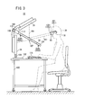
- the three-dimensional image display apparatus 22 includes a base 102 mounted on the upper surface of a table 100, a support column 104 extending upwardly from the base 102, the left-eye image display unit 34, e.g., a liquid-crystal display unit or the like, supported in an upright position on the support column 104, a curved support arm (support member) 106 extending upwardly from a rear surface of the left-eye image display unit 34, the right-eye image display unit 36, e.g., a liquid-crystal display unit or the like, supported on the support arm 106 obliquely to the left-eye image display unit 34, a half-silvered mirror support mechanism (position adjusting mechanism) 107 supported by the support arm 106 and extending in a space between the upper surface of the table 100 and the right-eye image display unit 36 in front of the left-eye image display unit 34, the half-silvered mirror 38 supported by the half-silvered mirror support mechanism 107
- the half-silvered mirror support mechanism 107 comprises a cylindrical shaft 108 extending horizontally through the support arm 106, a substantially U-shaped angularly movable member 112 angularly movably supported on the opposite ends of the shaft 108 for angular movement about the shaft 108 between the left-eye image display unit 34 and the right-eye image display unit 36, and a (substantially rectangular) frame 114 connected to the angularly movable member 112 and supporting the peripheral edges of the half-silvered mirror 38.
- the angularly movable member 112, the frame 114, and the half-silvered mirror 38 are locked against angular movement about the shaft 108 when the observer 20 turns and displaces a handle 110 toward the shaft 108.
- the angularly movable member 112, the frame 114, and the half-silvered mirror 38 can thus be fixed at a desired angle with respect to the left-eye image display unit 34 and the right-eye image display unit 36.
- the frame 114 that supports the peripheral edges of the half-silvered mirror 38 will be described in detail below with reference to FIGS. 4 through 9B .
- the frame 114 has a shape including a large opening which is open toward the observer 20 (see FIG. 2 ).
- the frame 114 includes a groove 250 defined therein which is open inwardly toward the opening of the frame 114.
- the groove 250 has a width in a direction along the thickness of the frame 114 and hence the half-silvered mirror 38.
- the width of the groove 250 is greater than the thickness of the half-silvered mirror 38.
- the groove 250 has a depth along the plane of the frame 114 and hence the half-silvered mirror 38.
- the depth of the groove 250 is large enough for the peripheral edges of the half-silvered mirror 38 to be received in the groove 250 (see FIGS. 5 and 7 ).
- the frame 114 has threaded holes 256a through 256d defined in a lower wall thereof at respective positions aligned with the four corners of the half-silvered mirror 38.
- the threaded holes 256a through 256d extend through the lower wall of the frame 114 and are open to the groove 250 in the direction along the thickness of the frame 114.
- Screws (position adjusting members) 258a through 258d are threaded respectively in the threaded holes 256a through 256d.
- the screws 258a through 258d that are threaded respectively in the threaded holes 256a through 256d have respective tip ends which can be held in contact with a lower surface at the four corners of the half-silvered mirror 38.
- a screwdriver not shown
- the heights or vertical positions in the groove 250 of the peripheral edges of the half-silvered mirror 38 can be adjusted (see FIGS. 9A and 9B ).
- the width of the groove 250 in the direction along the thickness of the frame 114 and hence the half-silvered mirror 38 represents a position adjusting range in which the heights or vertical positions of the peripheral edges of the half-silvered mirror 38 are adjustable.
- FIG. 9A shows the manner in which the peripheral edge of the half-silvered mirror 38 near the screws 258a, 258c is raised, i.e., its height or vertical position is increased, within the groove 250 by tightening the screws 258a, 258c, and the peripheral edge of the half-silvered mirror 38 near the screws 258b, 258d is lowered, i.e., its height or vertical position is reduced, within the groove 250 by loosening the screws 258b, 258d.
- FIG. 9A shows the manner in which the peripheral edge of the half-silvered mirror 38 near the screws 258a, 258c is raised, i.e., its height or vertical position is increased, within the groove 250 by tightening the screws 258a, 258c, and the peripheral edge of the half-silvered mirror 38 near the screws 258b, 258d is lowered, i.e., its height or vertical position is reduced, within the groove 250 by loosening the screws 258b, 258
- FIG. 9B shows the manner in which the peripheral edge of the half-silvered mirror 38 near the screws 258a, 258c is lowered, i.e., its height or vertical position is reduced, within the groove 250 by loosening the screws 258a, 258c, and the peripheral edge of the half-silvered mirror 38 near the screws 258b, 258d is raised, i.e., its height or vertical position is increased, within the groove 250 by tightening the screws 258b, 258d.
- the stereoscope 40 comprises a frame 118, a polarizer lens 120r fixed to the frame 118 for the right eye 46r, and a polarizer lens 1201 fixed to the frame 118 for the left eye 461.
- the left-eye image display unit 34 displays the left-eye image 421 including a breast image 1301 representing the breast 14 on a display screen 122 thereof.
- the right-eye image display unit 36 displays the right-eye image 42r including a breast image 130r representing the breast 14 on a display screen 124 thereof.
- the half-silvered mirror 38 transmits the display light 441 from the left-eye image 421, which is a two-dimensional image, therethrough to the stereoscope 40 worn by the observer 20, and reflects the display light 44r from the right-eye image 42r, which is a two-dimensional image, therefrom to the stereoscope 40 worn by the observer 20 (see FIG. 3 ).
- the polarizer lens 120r of the stereoscope 40 transmits therethrough only the display light 44r which is parallel to the absorption axis of the polarizer lens 120r, and the polarizer lens 1201 of the stereoscope 40 transmits therethrough only the display light 441 which is parallel to the absorption axis of the polarizer lens 1201.
- the observer 20 who is wearing the stereoscope 40 sees the right-eye image 42r represented by the display light 44r with the right eye 46r, and sees the left-eye image 421 represented by the display light 441 with the left eye 461, thereby visually recognizing the three-dimensional image (3D image) of the breast 14.
- FIG. 10 is a detailed block diagram of the radiographic image capturing system 10.
- the mammographic apparatus 18 further includes a display operation panel (display operation unit) 64, an image capturing condition memory 150, a radiation source controller 152, a detector controller 154, an image information memory 156, and a compression plate controller 158.
- a display operation panel display operation unit
- an image capturing condition memory 150 a radiation source controller 152
- a detector controller 154 a detector controller 154
- an image information memory 156 a compression plate controller 158.
- the image capturing condition memory 150 stores image capturing conditions including a tube current and a tube voltage of the radiation source 26, irradiation doses and irradiation times of the radiation 16b, 16c, image capturing angles (+ ⁇ 1, - ⁇ 1) in the stereographic image capturing process, an image capturing sequence, etc.
- the image capturing conditions can be set (stored) in the image capturing condition memory 150 by the doctor or the radiological technician, i.e., the observer 20 when it operates the display operation panel 64.
- the radiation source controller 152 controls the radiation source 26 according to the image capturing conditions.
- the compression plate controller 158 controls the compression plate 32 to move in the directions indicated by the arrow Z.
- the detector controller 154 controls the solid-state detector 28 to store the right-eye image 42r and the left-eye image 421 which have been converted from the radiation 16b, 16c by the solid-state detector 28, in the image information memory 156.
- the three-dimensional image display apparatus 22 also includes a controller 160, an image processor 162, and an image information memory 164.
- the controller 160 acquires the right-eye image 42r and the left-eye image 421 stored in the image information memory 156, and controls the image processor 162 to perform an image processing process on the right-eye image 42r and the left-eye image 421.
- the controller 160 displays the processed left-eye image 421 on the display screen 122 (see FIG. 2 ) of the left-eye image display unit 34 and also displays the processed right-eye image 42r on the display screen 124 of the right-eye image display unit 36.
- the controller 160 can also perform processing sequences according to instructions input from the observer 20 through the operating unit 116.
- the image information memory 164 stores the processed right-eye image 42r and the processed left-eye image 421.
- the image information memory 164 stores, in advance, a grid-like right-eye image 260r shown in FIG. 11A and a grid-like left-eye image 2601 shown in FIG. 11B .
- the grid-like right-eye image 260r and the grid-like left-eye image 2601 are images to be used to adjust the position of the half-silvered mirror 38 as described below.
- the observer 20 may find the three-dimensional image blurred. If the observer 20 finds the three-dimensional image blurred, then in order to see the three-dimensional image as a sharper image, the observer 20 operates the operating unit 116 to instruct the controller 160 to display the grid-like right-eye image 260r and the grid-like left-eye image 2601.
- the controller 160 displays the grid-like left-eye image 2601 stored in the image information memory 164 on the display screen 122 of the left-eye image display unit 34 and also displays the grid-like right-eye image 260r stored in the image information memory 164 on the display screen 124 of the right-eye image display unit 36.
- Display light 2661 from the grid-like left-eye image 2601 displayed on the display screen 122 of the left-eye image display unit 34 travels obliquely upwardly toward the half-silvered mirror 38
- display light 266r from the grid-like right-eye image 260r displayed on the display screen 124 of the right-eye image display unit 36 travels obliquely downwardly toward the half-silvered mirror 38.
- the half-silvered mirror 38 transmits the display light 2661 therethrough and reflects the display light 266r therefrom, generating a grid-like combined image 262 (see FIG. 11C ) which is a combination of the right-eye image 260r represented by the display light 266r and the left-eye image 2601 represented by the display light 2661.
- the grid-like combined image 262 is viewed as including a blurred lower portion (see FIG. 11C ).
- the lower portion of the grid-like combined image 262 is blurred because since the observer 20 has changed its posture vertically and the half-silvered mirror 38 is no longer in an appropriate position with respect to the observer 20, a positional deviation has occurred between the display light 266r of the right-eye image 260r and the display light 2661 of the left-eye image 2601 which travel from the half-silvered mirror 38 toward the stereoscope 40.
- the observer 20 now uses the screwdriver, not shown, to adjust the axial positions of the screws 258a through 258d threaded in the respective threaded holes 256a through 256d in the frame 114 to finely adjust the heights or vertical positions in the groove 250 of the peripheral edges of the half-silvered mirror 38 until the displayed grid-like combined image 262 will not be blurred. For example, if the grid-like combined image 262 has its lower portion blurred as shown in FIG. 11C , then the observer 20 turns the screws 258b, 258d corresponding to the lower portion of the grid-like combined image 262 with the screwdriver while viewing the grid-like combined image 262 which is displayed. The screws 258b, 258d are now adjusted in their axial positions to raise the height or vertical position in the groove 250 of the peripheral edge of the half-silvered mirror 38 near the screws 258b, 258d, as shown in FIG. 9B .
- the displayed grid-like combined image 262 will become free of blurs, and the observer 20 can view a sharp grid-like combined image 264 which is displayed, as shown in FIG. 11D .
- the three-dimensional image display apparatus 22 displays a three-dimensional image of the breast 14.
- step S1 shown in FIG. 12 the doctor or the radiological technician, i.e., the observer 20, operates the display operation panel 64 of the mammographic apparatus 18 to store image capturing conditions depending on the breast 14 of the subject 12 (see FIGS. 1 and 10 ) in the image capturing condition memory 150 prior to a stereographic image capturing process to be performed on the breast 14.
- step S2 the doctor or the radiological technician places the compression plate 32 between the radiation source 26 and the image capturing base 30.
- step S3 the doctor or the radiological technician positions the breast 14 of the subject 12. Specifically, the doctor or the radiological technician places the breast 14 on the image capturing base 30 at a position confronting the compression plate 32, and then operates the display operation panel 64 to energize the compression plate controller 158 to move the compression plate 32 toward the image capturing base 30 in the downward direction indicated by the arrow Z (see FIG. 10 ). The breast 14 is now compressed and secured in place by the image capturing base 30 and the compression plate 32.
- the mammographic apparatus 18 energizes the radiation source 26 to perform a stereographic image capturing process on the breast 14 in step S4.
- the radiation source controller 152 places the radiation source 26 in the position B. Then, the doctor or the radiological technician turns on an exposure switch, not shown, displayed on the display operation panel 64, causing the radiation source controller 152 to control the radiation source 26 in the position B according to the image capturing conditions stored in the image capturing condition memory 150.
- the radiation source 26 in the position B emits the radiation 16b, which is applied through the compression plate 32 to the breast 14.
- the radiation 16b is transmitted through the breast 14, and is detected by the solid-state detector 28 as representing a first radiographic image (right-eye image 42r).
- the detector controller 154 controls the solid-state detector 28 to acquire the first radiographic image (right-eye image 42r) and stores the acquired right-eye image 42r in the image information memory 156.
- the mammographic apparatus 18 moves the radiation source 26 to the position C and captures a second radiographic image at the position C in the same manner as it captured the first radiographic image at the position B.
- the doctor or the radiological technician operates the display operation panel 64 to instruct the mammographic apparatus 18 to start capturing a second radiographic image.
- the radiation source controller 152 moves the radiation source 26 from the position B to the position C and places the radiation source 26 in the position C. Then, the doctor or the radiological technician turns on the exposure switch of the display operation panel 64, causing the radiation source controller 152 to control the radiation source 26 in the position C according to the image capturing conditions stored in the image capturing condition memory 150.
- the radiation source 26 in the position C emits the radiation 16c, which is applied through the compression plate 32 to the breast 14.
- the radiation 16c is transmitted through the breast 14, and is detected by the solid-state detector 28 as representing a second radiographic image (left-eye image 421).
- the detector controller 154 controls the solid-state detector 28 to acquire the second radiographic image (left-eye image 421) and stores the acquired left-eye image 421 in the image information memory 156.
- the image information memory 156 stores therein two radiographic images, i.e., the right-eye image 42r and the left-eye image 421 each comprising a two-dimensional image.
- step S5 the controller 160 of the three-dimensional image display apparatus 22 (see FIGS. 1 through 3 , 10 ) acquires the right-eye image 42r and the left-eye image 421 from the image information memory 156 automatically or based on an image acquiring instruction input from the observer 20 through the operating unit 116.
- the controller 160 then outputs the right-eye image 42r and the left-eye image 421 which have been acquired to the image processor 162.
- the image processor 162 performs a predetermined image processing process on the right-eye image 42r and the left-eye image 421.
- the controller 160 then stores the right-eye image 42r and the left-eye image 421 which have been processed in the image information memory 164.
- step S6 the three-dimensional image display apparatus 22 displays a three-dimensional image of the breast 14.
- the observer 20 has been working on the mammographic apparatus 18 for performing the stereographic image capturing process in steps S1 through S4. Therefore, when the three-dimensional image display apparatus 22 displays a three-dimensional image of the breast 14, the observer 20 may possibly view the displayed three-dimensional image of the breast 14 as blurred due to a change in the posture of the observer 20 which may have been caused in steps S1 through S4.
- the observer 20 operates the operating unit 116 to instruct the controller 160 to display the grid-like right-eye image 260r and the grid-like left-eye image 2601 in step S61 (see FIG. 13 ) of a subroutine in step S6.
- the controller 160 displays the grid-like left-eye image 2601 stored in the image information memory 164 on the display screen 122 of the left-eye image display unit 34 and also displays the grid-like right-eye image 260r stored in the image information memory 164 on the display screen 124 of the right-eye image display unit 36.
- Display light 2661 from the grid-like left-eye image 2601 displayed on the display screen 122 of the left-eye image display unit 34 travels obliquely upwardly toward the half-silvered mirror 38
- display light 266r from the grid-like right-eye image 260r displayed on the display screen 124 of the right-eye image display unit 36 travels obliquely downwardly toward the half-silvered mirror 38.
- the half-silvered mirror 38 transmits the display light 2661 therethrough and reflects the display light 266r therefrom, generating a grid-like combined image 262 which is a combination of the right-eye image 260r represented by the display light 266r and the left-eye image 2601 represented by the display light 2661.
- step S62 if the observer 20 views the grid-like combined image 262 as blurred in its lower portion as shown in FIG. 11C (YES: step S62), then the observer 20 judges that the half-silvered mirror 38 has not been adjusted to an appropriate position. While viewing the grid-like combined image 262, the observer 20 uses the screwdriver to turn the screws 258b, 258d corresponding in position to the lower portion of the grid-like combined image 262 to adjust the axial positions of the screws 258b, 258d, raising the height or vertical position in the groove 250 of the peripheral edge of the half-silvered mirror 38 near the screws 258b, 258d, in step S63.
- step S62 If the observer 20 views the grid-like combined image 264 as sharp shown in FIG. 11D (NO: step S62), then the observer 20 judges that the half-silvered mirror 38 has been adjusted to an appropriate position, and completes the position adjusting process in step S64.
- step S65 the observer 20 operates the operating unit 116 to instruct the controller 160 to display a three-dimensional image of the breast 14.
- the controller 160 displays the processed left-eye image 421 stored in the image information memory 164 on the display screen 122 of the left-eye image display unit 34 and also displays the processed right-eye image 42r stored in the image information memory 164 on the display screen 124 of the right-eye image display unit 36.
- Display light 441 from the left-eye image 421 displayed on the display screen 122 travels obliquely upwardly toward the half-silvered mirror 38
- display light 44r from the right-eye image 42r displayed on the display screen 124 travels obliquely downwardly toward the half-silvered mirror 38.
- the half-silvered mirror 38 transmits the display light 441 from the left-eye image 421 therethrough to the stereoscope 40 worn by the observer 20, and reflects the display light 44r from the right-eye image 42r therefrom to the stereoscope 40 worn by the observer 20.
- the polarizer lens 120r of the stereoscope 40 transmits therethrough only the display light 44r which is parallel to the absorption axis of the polarizer lens 120r, and the polarizer lens 1201 of the stereoscope 40 transmits therethrough only the display light 441 which is parallel to the absorption axis of the polarizer lens 1201.
- the observer 20 who is wearing the stereoscope 40 sees the right-eye image 42r represented by the display light 44r with the right eye 46r, and sees the left-eye image 421 represented by the display light 441 with the left eye 461, thereby visually recognizing the three-dimensional image of the breast 14 easily.
- step S65 Since the three-dimensional image displayed in step S65 is an image displayed after the position adjusting process of the half-silvered mirror 38 in steps S62, 63 has been completed, the observer 20 can view the displayed three-dimensional image as a sharp image.
- step S65 is immediately carried out after step S64.
- the observer 20 can use the position adjusting mechanism 107 to adjust the position of the half-silvered mirror 38 with respect to the observer 20 for adjusting a blur in the grid-like combined image 262 due to a positional deviation between the right-eye image 260r and the left-eye image 2601 when the combined image 262 is generated.
- the observer 20 may use the position adjusting mechanism 107 to adjust the position of the half-silvered mirror 38 until the blur in the grid-like combined image 262 is minimized. Accordingly, the position of the half-silvered mirror 38 can be adjusted appropriately.
- the right-eye image 260r and the left-eye image 2601 are essentially identical grid-like images, if there is no positional deviation between the right-eye image 260r and the left-eye image 2601, then the grid-like combined image 264 which is generated by combining the right-eye image 260r and the left-eye image 2601 is a sharp image free of blurs. By directly viewing the combined image 264, therefore, the observer 20 can easily judge that it is not necessary to adjust the position of the half-silvered mirror 38 using the position adjusting mechanism 107.
- the grid-like combined image 262 which is generated by combining the right-eye image 260r and the left-eye image 2601 is a blurred image.
- the observer 20 can easily judge that the combined image 262 is blurred due to the positional deviation between the right-eye image 260r and the left-eye image 2601.
- the observer 20 can also identify the location of the blur in the combined image 262, and decide that it is necessary to adjust the position of the half-silvered mirror 38 using the position adjusting mechanism 107.
- the observer 20 can adjust the half-silvered mirror 38 to its appropriate position and hence can view a sharp three-dimensional image of the breast 14.
- the width of the groove 250 in the frame 114 which is greater than the thickness of the half-silvered mirror 38 represents a position adjusting range in which the position of the half-silvered mirror 38 is adjustable.
- the position of the half-silvered mirror 38 can be finely adjusted in the position adjusting range along the thickness of the half-silvered mirror 38 by using the screws 258a through 258d.
- the frame 114 has the threaded holes 256a through 256d defined in the lower wall thereof at the respective positions aligned with the four corners of the half-silvered mirror 38, and the screws 258a through 258d are threaded respectively in the threaded holes 256a through 256d and held against the half-silvered mirror 38.
- the position of the half-silvered mirror 38 along the thickness thereof can be adjusted wholly or locally by turning all or selected ones of the screws 258a through 258d. Since only the screws 258a through 258d need to be turned, it is easy to finely adjust the position of the half-silvered mirror 38 along the thickness thereof.
- the grid-like combined image 262 is blurred in a portion thereof, e.g., in its lower portion, then those of the screws 258a through 258d which are close to the portion of the half-silvered mirror 38 that corresponds to the blurred portion of the grid-like combined image 262 are turned to locally adjust the position of the half-silvered mirror 38.
- the position of the half-silvered mirror 38 can thus be adjusted precisely and accurately.
- the observer 20 manually turns the screws 258a through 258d to adjust the position of the half-silvered mirror 38 while viewing the grid-like combined image that is displayed.
- the grid-like combined image may be captured by a CCD camera, not shown, and the screws 258a through 258d may be automatically adjusted in their positions until the captured grid-like combined image becomes sharp.
Landscapes
- Physics & Mathematics (AREA)
- General Physics & Mathematics (AREA)
- Optics & Photonics (AREA)
- Engineering & Computer Science (AREA)
- Multimedia (AREA)
- Signal Processing (AREA)
- Testing, Inspecting, Measuring Of Stereoscopic Televisions And Televisions (AREA)
Abstract
A three-dimensional image display apparatus (22) includes an image combiner (38) which combines a grid-like right-eye image (260r) and a grid-like left-eye image (2601), which are substantially identical to each other, into a grid-like combined image (262, 264), and a position adjusting mechanism (107) which adjusts a position of the image combiner (38) with respect to an observer (20) to adjust a blur in the grid-like combined image (262, 264) due to a positional deviation between the grid-like right-eye image (260r) and the grid-like left-eye image (2601).
Description
- The present invention relates to a three-dimensional image display apparatus for enabling an observer to view a three-dimensional image based on a combined image which is produced by combining a two-dimensional image (right-eye image) to be seen by the right eye of the observer and a two-dimensional image (left-eye image) to be seen by the left eye of the observer, and a method of adjusting the combined image that is displayed.
- Heretofore, there has been known in the art a three-dimensional image display apparatus for enabling an observer to view, as a three-dimensional image, a combined image using a stereoscope by displaying a two-dimensional image (right-eye image) for the right eye of the observer on a right-eye image display device, displaying a two-dimensional image (left-eye image) for the left eye of the observer on a left-eye image display device, and combining the right-eye image and the left-eye image into the combined image with an image combiner.
- If the observer who views the three-dimensional image changes its posture, then the observer finds it difficult to see the three-dimensional image. Therefore, it is desirable to appropriately adjust the position of the image combiner with respect to the observer each time the posture of the observer changes.
- Conventional techniques for adjusting displayed three-dimensional images are disclosed in Japanese Laid-Open Patent Publication No.
2009-122895 2007-279445 3324694 - However, the display adjusting techniques disclosed in the above publications do not adjust the position of the image combiner with respect to the observer when the posture of the observer with respect to the three-dimensional image changes. Therefore, the conventional display adjusting techniques fail to solve the above problem even if they are applied to three-dimensional image display apparatus.
- It is an object of the present invention to appropriately adjust the position of an image combiner with respect to an observer each time the posture of the observer who views a three-dimensional image changes.
- To achieve the above object, according to the present invention, there is provided a three-dimensional image display apparatus comprising a right-eye image display unit for displaying a right-eye image, which is two-dimensional, to be seen by a right eye of an observer, a left-eye image display unit for displaying a left-eye image, which is two-dimensional, to be seen by a left eye of the observer, an image combiner for combining the grid-like right-eye image and the grid-like left-eye image, which are substantially identical to each other, into a grid-like combined image, and a position adjusting mechanism for adjusting a position of the image combiner with respect to the observer to adjust a blur in the grid-like combined image due to a positional deviation between the grid-like right-eye image and the grid-like left-eye image.
- According to the present invention, there is also provided a method of adjusting an image that is displayed, comprising the steps of displaying on a right-eye image display unit a right-eye image, which is two-dimensional, to be seen by a right eye of an observer, displaying on a left-eye image display unit a left-eye image, which is two-dimensional, to be seen by a left eye of the observer, combining the grid-like right-eye image and the grid-like left-eye image, which are substantially identical to each other, into a grid-like combined image with an image combiner, and adjusting a position of the image combiner with respect to the observer to adjust a blur in the grid-like combined image due to a positional deviation between the grid-like right-eye image and the grid-like left-eye image.
- With the present invention, the observer can use the position adjusting mechanism to adjust the position of the image combiner with respect to the observer for adjusting a blur in the grid-like combined image due to a positional deviation between the right-eye image and the left-eye image. Each time the posture of the observer who views a three-dimensional image is changed, the observer may use the position adjusting mechanism to adjust the position of the image combiner until the blur in the grid-like combined image is minimized. Accordingly, the position of the image combiner can be adjusted appropriately.
- Since the right-eye image and the left-eye image are essentially identical grid-like images, if there is no positional deviation between the right-eye image and the left-eye image, then the grid-like combined image which is generated by combining the right-eye image and the left-eye image is a sharp image free of blurs. By directly viewing the sharp combined image, therefore, the observer can easily judge that it is not necessary to adjust the position of the half-silvered mirror using the position adjusting mechanism.
- Conversely, if there is a positional deviation between the right-eye image and the left-eye image, then the grid-like combined image which is generated by combining the right-eye image and the left-eye image is a blurred image. By directly viewing the blurred combined image, therefore, the observer can easily judge that the combined image is blurred due to the positional deviation between the right-eye image and the left-eye image. The observer can also identify the location of the blur in the combined image, and decide that it is necessary to adjust the position of the half-silvered mirror using the position adjusting mechanism.
- According to the present invention, therefore, even when the observer changes its posture, the observer can adjust the image combiner to its appropriate position and hence can view a sharp three-dimensional image.
- One image display unit of the right-eye image display unit and the left-eye image display unit may be disposed in confronting relation to the observer, and the other image display unit of the right-eye image display unit and the left-eye image display unit may be disposed above the one image display unit and may be angularly spaced therefrom. The image combiner may comprise a half-silvered mirror disposed between the one image display unit and the other image display unit. The half-silvered mirror may transmit the image which is displayed by the one image display unit therethrough toward the observer and may reflect the image which is displayed by the other image display unit therefrom toward the observer, thereby outputting the images as the combined image to the observer.
- The three-dimensional image display apparatus may further comprise a support member extending from the one image display unit and supporting the other image display unit. The position adjusting mechanism may comprise a shaft extending substantially horizontally through the support member, an angularly movable member angularly movably supported on opposite ends of the shaft for angular movement about the shaft between the one image display unit and the other image display unit, and a frame connected to the angularly movable member and supporting peripheral edges of the half-silvered mirror which is substantially rectangular in shape. The frame may have a groove defined therein which receives the peripheral edges of the half-silvered mirror therein. The groove may have a width along thickness of the half-silvered mirror, the width being greater than the thickness of the half-silvered mirror. The frame may include position adjusting members for positionally adjusting the peripheral edges of the half-silvered mirror within the groove along the thickness of the half-silvered mirror.
- Since the width of the groove is greater than the thickness of the half-silvered mirror, the width provides a position adjusting range in which the half-silvered mirror is positionally adjustable. The position adjusting members make it possible to finely adjust the position of the half-silvered mirror in the position adjusting range along the thickness of the half-silvered mirror.
- The position adjusting members may be disposed on the frame at respective four corners of the half-silvered mirror. The position of the half-silvered mirror can thus be adjusted wholly or locally along the thickness of the half-silvered mirror.
- The frame may have threaded holes defined therein which are open to the groove in a direction along the thickness of the half-silvered mirror. The position adjusting members may comprise screws, respectively, threaded in the threaded holes, respectively, and having respective tip ends held in contact with the peripheral edges of the half-silvered mirror. Therefore, the position of the half-silvered mirror can easily be adjusted minutely along the thickness of the half-silvered mirror.
- If the grid-like combined image is blurred in a portion thereof, then those of the position adjusting members which are close to a portion of the half-silvered mirror that corresponds to the blurred portion of the grid-like combined image may be used to positionally adjust the half-silvered mirror. Inasmuch as the position of the half-silvered mirror can be adjusted locally, the position of the half-silvered mirror can be adjusted precisely and accurately.
- The above and other objects, features, and advantages of the present invention will become more apparent from the following description when taken in conjunction with the accompanying drawings in which a preferred embodiment of the present invention is shown by way of illustrative example.
-
-
FIG. 1 is a schematic view of a radiographic image capturing system incorporating a three-dimensional image display apparatus according to an embodiment of the present invention; -
FIG. 2 is a perspective view of the three-dimensional image display apparatus shown inFIG. 1 ; -
FIG. 3 is a side elevational view of the three-dimensional image display apparatus shown inFIG. 2 ; -
FIG. 4 is a cross-sectional view taken along line IV - IV ofFIG. 3 ; -
FIG. 5 is a cross-sectional view taken along line V - V ofFIG. 3 ; -
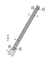
FIG. 6 is a cross-sectional view taken along line VI - VI ofFIG. 3 ; -
FIG. 7 is a cross-sectional view taken along line VII - VII ofFIG. 3 ; -
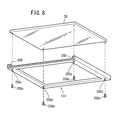
FIG. 8 is an exploded perspective view of a positional adjusting mechanism and a half-silvered mirror shown inFIGS. 2 and3 ; -
FIGS. 9A and 9B are cross-sectional views showing the manner in which the half-silvered mirror is positionally adjusted; -
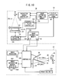
FIG. 10 is a detailed block diagram of the radiographic image capturing system shown inFIG. 1 ; -
FIG. 11A is a view showing a right-eye image; -
FIG. 11B is a view showing a left-eye image; -
FIGS. 11C and 11D are views showing a combined image; -
FIG. 12 is a flowchart of an operation sequence of the radiographic image capturing system shown inFIGS. 1 and10 ; and -
FIG. 13 is a flowchart of a subroutine in step S6 shown inFIG. 12 . - A three-dimensional image display apparatus according to an embodiment of the present invention and a method of adjusting a combined image that is displayed by the three-dimensional image display apparatus will be described below with reference to
FIGS. 1 through 13 . - First, a radiographic
image capturing system 10 incorporating a three-dimensionalimage display apparatus 22 according to an embodiment of the present invention will be described below with reference toFIG. 1 . - As shown in
FIG. 1 , the radiographicimage capturing system 10 basically comprises amammographic apparatus 18 for performing a stereographic image capturing process to applyradiation breast 14 of asubject 12 for thereby acquiring two radiographic images each representing thebreast 14, and the three-dimensionalimage display apparatus 22 for enabling anobserver 20, such as a doctor, a radiological technician, or the like, to view a three-dimensional image based on the two radiographic images from themammographic apparatus 18, one of the two radiographic images being used as a two-dimensional image (right-eye image) 42r for theright eye 46r of theobserver 20 and the other as a two-dimensional image (left-eye image) 421 for theleft eye 461 of theobserver 20. - The
mammographic apparatus 18 comprises aradiation source 26 for applying theradiation breast 14 respectively from a position B that is angularly spaced an angle of +01 from a position A (θ = 0°) on acentral axis 24 extending substantially centrally through thebreast 14 and a position C that is angularly spaced an angle of -θ1 from the position A, a solid-state detector 28 for detecting theradiation breast 14 and converting the detectedradiation eye image 42r and the left-eye image 421, an image capturingbase 30 for holding thebreast 14 thereon, theimage capturing base 30 housing the solid-state detector 28 therein, and acompression plate 32 displaceable toward theimage capturing base 30 away from theradiation source 26 for compressing thebreast 14 against theimage capturing base 30. - In
FIG. 1 , theradiation 16b is applied from theradiation source 26 disposed in the position B to thebreast 14, and theradiation 16b that has passed through thebreast 14 is detected and converted into the right-eye image 42r by the solid-state detector 28. Theradiation 16c is applied from theradiation source 26 disposed in the position C to thebreast 14, and theradiation 16c that has passed through thebreast 14 is detected and converted into the left-eye image 421 by the solid-state detector 28. Thecentral axis 24 extends substantially centrally through thebreast 14 substantially perpendicularly to the upper surface of theimage capturing base 30 and the solid-state detector 28. - The three-dimensional
image display apparatus 22 comprises a left-eyeimage display unit 34 for displaying the left-eye image 421, a right-eyeimage display unit 36 for displaying the right-eye image 42r, the right-eyeimage display unit 36 being angularly spaced a predetermined angle from the left-eyeimage display unit 34, a (substantially rectangular) half-silvered mirror (image combiner) 38 disposed in a predetermined position between the left-eyeimage display unit 34 and the right-eyeimage display unit 36, for transmitting display light 441 from the left-eye image 421 displayed by the left-eyeimage display unit 34, therethrough to theobserver 20, and reflectingdisplay light 44r from the right-eye image 42r displayed by the right-eyeimage display unit 36, therefrom to theobserver 20, and astereoscope 40 to be worn by theobserver 20. - The
observer 20 sees, through thestereoscope 40, the right-eye image 42r represented by thedisplay light 44r from the half-silveredmirror 38 with theright eye 46r, and the left-eye image 421 represented by the display light 441 from the half-silveredmirror 38 with theleft eye 461, thereby visually recognizing (a combined image of) the right-eye image 42r and the left-eye image 421 as a three-dimensional image (3D image). - Specific structural details of the three-dimensional
image display apparatus 22 will be described below with reference toFIGS. 2 through 9B . - As shown in
FIG. 2 , the three-dimensional image display apparatus 22 includes a base 102 mounted on the upper surface of a table 100, a support column 104 extending upwardly from the base 102, the left-eye image display unit 34, e.g., a liquid-crystal display unit or the like, supported in an upright position on the support column 104, a curved support arm (support member) 106 extending upwardly from a rear surface of the left-eye image display unit 34, the right-eye image display unit 36, e.g., a liquid-crystal display unit or the like, supported on the support arm 106 obliquely to the left-eye image display unit 34, a half-silvered mirror support mechanism (position adjusting mechanism) 107 supported by the support arm 106 and extending in a space between the upper surface of the table 100 and the right-eye image display unit 36 in front of the left-eye image display unit 34, the half-silvered mirror 38 supported by the half-silvered mirror support mechanism 107 in a given position between the left-eye image display unit 34 and the right-eye image display unit 36, an operating unit 116 such as a keyboard or the like to be operated by the observer 20, and the stereoscope 40 to be worn by the observer 20. - The half-silvered
mirror support mechanism 107 comprises acylindrical shaft 108 extending horizontally through thesupport arm 106, a substantially U-shaped angularlymovable member 112 angularly movably supported on the opposite ends of theshaft 108 for angular movement about theshaft 108 between the left-eyeimage display unit 34 and the right-eyeimage display unit 36, and a (substantially rectangular)frame 114 connected to the angularlymovable member 112 and supporting the peripheral edges of the half-silveredmirror 38. - The angularly
movable member 112, theframe 114, and the half-silveredmirror 38 are locked against angular movement about theshaft 108 when theobserver 20 turns and displaces ahandle 110 toward theshaft 108. The angularlymovable member 112, theframe 114, and the half-silveredmirror 38 can thus be fixed at a desired angle with respect to the left-eyeimage display unit 34 and the right-eyeimage display unit 36. - The
frame 114 that supports the peripheral edges of the half-silveredmirror 38 will be described in detail below with reference toFIGS. 4 through 9B . - The
frame 114 has a shape including a large opening which is open toward the observer 20 (seeFIG. 2 ). Theframe 114 includes agroove 250 defined therein which is open inwardly toward the opening of theframe 114. Thegroove 250 has a width in a direction along the thickness of theframe 114 and hence the half-silveredmirror 38. The width of thegroove 250 is greater than the thickness of the half-silveredmirror 38. Thegroove 250 has a depth along the plane of theframe 114 and hence the half-silveredmirror 38. The depth of thegroove 250 is large enough for the peripheral edges of the half-silveredmirror 38 to be received in the groove 250 (seeFIGS. 5 and7 ). When the peripheral edges of the half-silveredmirror 38 are placed in thegroove 250, the peripheral edges of the half-silveredmirror 38 are supported by theframe 114. - As shown in
FIGS. 3 ,4 ,6 ,8 ,9A, and 9B , theframe 114 has threadedholes 256a through 256d defined in a lower wall thereof at respective positions aligned with the four corners of the half-silveredmirror 38. The threadedholes 256a through 256d extend through the lower wall of theframe 114 and are open to thegroove 250 in the direction along the thickness of theframe 114. Screws (position adjusting members) 258a through 258d are threaded respectively in the threadedholes 256a through 256d. - The
screws 258a through 258d that are threaded respectively in the threadedholes 256a through 256d have respective tip ends which can be held in contact with a lower surface at the four corners of the half-silveredmirror 38. When thescrews 258a through 258d are turned by a screwdriver, not shown, to finely adjust their axial positions, the heights or vertical positions in thegroove 250 of the peripheral edges of the half-silveredmirror 38 can be adjusted (seeFIGS. 9A and 9B ). According to the present embodiment, the width of thegroove 250 in the direction along the thickness of theframe 114 and hence the half-silveredmirror 38 represents a position adjusting range in which the heights or vertical positions of the peripheral edges of the half-silveredmirror 38 are adjustable. -
FIG. 9A shows the manner in which the peripheral edge of the half-silveredmirror 38 near thescrews groove 250 by tightening thescrews mirror 38 near thescrews groove 250 by loosening thescrews FIG. 9B shows the manner in which the peripheral edge of the half-silveredmirror 38 near thescrews groove 250 by loosening thescrews mirror 38 near thescrews groove 250 by tightening thescrews - As shown in
FIG. 2 , thestereoscope 40 comprises aframe 118, apolarizer lens 120r fixed to theframe 118 for theright eye 46r, and apolarizer lens 1201 fixed to theframe 118 for theleft eye 461. The left-eyeimage display unit 34 displays the left-eye image 421 including abreast image 1301 representing thebreast 14 on adisplay screen 122 thereof. The right-eyeimage display unit 36 displays the right-eye image 42r including abreast image 130r representing thebreast 14 on adisplay screen 124 thereof. - As described above, the half-silvered
mirror 38 transmits the display light 441 from the left-eye image 421, which is a two-dimensional image, therethrough to thestereoscope 40 worn by theobserver 20, and reflects thedisplay light 44r from the right-eye image 42r, which is a two-dimensional image, therefrom to thestereoscope 40 worn by the observer 20 (seeFIG. 3 ). Thepolarizer lens 120r of thestereoscope 40 transmits therethrough only thedisplay light 44r which is parallel to the absorption axis of thepolarizer lens 120r, and thepolarizer lens 1201 of thestereoscope 40 transmits therethrough only thedisplay light 441 which is parallel to the absorption axis of thepolarizer lens 1201. Theobserver 20 who is wearing thestereoscope 40 sees the right-eye image 42r represented by thedisplay light 44r with theright eye 46r, and sees the left-eye image 421 represented by thedisplay light 441 with theleft eye 461, thereby visually recognizing the three-dimensional image (3D image) of thebreast 14. -
FIG. 10 is a detailed block diagram of the radiographicimage capturing system 10. - Components of the radiographic
image capturing system 10 which have not been described above with reference toFIGS. 1 through 9B will be described below with reference toFIG. 10 . - As shown in
FIG. 10 , themammographic apparatus 18 further includes a display operation panel (display operation unit) 64, an image capturingcondition memory 150, aradiation source controller 152, adetector controller 154, animage information memory 156, and acompression plate controller 158. - The image capturing
condition memory 150 stores image capturing conditions including a tube current and a tube voltage of theradiation source 26, irradiation doses and irradiation times of theradiation condition memory 150 by the doctor or the radiological technician, i.e., theobserver 20 when it operates thedisplay operation panel 64. Theradiation source controller 152 controls theradiation source 26 according to the image capturing conditions. Thecompression plate controller 158 controls thecompression plate 32 to move in the directions indicated by the arrow Z. Thedetector controller 154 controls the solid-state detector 28 to store the right-eye image 42r and the left-eye image 421 which have been converted from theradiation state detector 28, in theimage information memory 156. - The three-dimensional
image display apparatus 22 also includes acontroller 160, animage processor 162, and animage information memory 164. - The
controller 160 acquires the right-eye image 42r and the left-eye image 421 stored in theimage information memory 156, and controls theimage processor 162 to perform an image processing process on the right-eye image 42r and the left-eye image 421. Thecontroller 160 displays the processed left-eye image 421 on the display screen 122 (seeFIG. 2 ) of the left-eyeimage display unit 34 and also displays the processed right-eye image 42r on thedisplay screen 124 of the right-eyeimage display unit 36. Thecontroller 160 can also perform processing sequences according to instructions input from theobserver 20 through theoperating unit 116. Theimage information memory 164 stores the processed right-eye image 42r and the processed left-eye image 421. - The
image information memory 164 stores, in advance, a grid-like right-eye image 260r shown inFIG. 11A and a grid-like left-eye image 2601 shown inFIG. 11B . The grid-like right-eye image 260r and the grid-like left-eye image 2601 are images to be used to adjust the position of the half-silveredmirror 38 as described below. - When the posture of the
observer 20 with respect to the three-dimensionalimage display apparatus 22 is vertically changed or when theobserver 20 views a three-dimensional image through thestereoscope 40 for a first image interpretation and diagnosis of the day, theobserver 20 may find the three-dimensional image blurred. If theobserver 20 finds the three-dimensional image blurred, then in order to see the three-dimensional image as a sharper image, theobserver 20 operates theoperating unit 116 to instruct thecontroller 160 to display the grid-like right-eye image 260r and the grid-like left-eye image 2601. - In response to the instruction from the
observer 20, thecontroller 160 displays the grid-like left-eye image 2601 stored in theimage information memory 164 on thedisplay screen 122 of the left-eyeimage display unit 34 and also displays the grid-like right-eye image 260r stored in theimage information memory 164 on thedisplay screen 124 of the right-eyeimage display unit 36. - Display light 2661 from the grid-like left-
eye image 2601 displayed on thedisplay screen 122 of the left-eyeimage display unit 34 travels obliquely upwardly toward the half-silveredmirror 38, and display light 266r from the grid-like right-eye image 260r displayed on thedisplay screen 124 of the right-eyeimage display unit 36 travels obliquely downwardly toward the half-silveredmirror 38. The half-silveredmirror 38 transmits the display light 2661 therethrough and reflects thedisplay light 266r therefrom, generating a grid-like combined image 262 (seeFIG. 11C ) which is a combination of the right-eye image 260r represented by thedisplay light 266r and the left-eye image 2601 represented by thedisplay light 2661. - Since the
observer 20 has instructed thecontroller 160 to display the right-eye image 260r and the left-eye image 2601 because the displayed three-dimensional image is blurred, when theobserver 20 views the combinedimage 262 through thestereoscope 40, the grid-likecombined image 262 is viewed as including a blurred lower portion (seeFIG. 11C ). The lower portion of the grid-likecombined image 262 is blurred because since theobserver 20 has changed its posture vertically and the half-silveredmirror 38 is no longer in an appropriate position with respect to theobserver 20, a positional deviation has occurred between thedisplay light 266r of the right-eye image 260r and thedisplay light 2661 of the left-eye image 2601 which travel from the half-silveredmirror 38 toward thestereoscope 40. - The
observer 20 now uses the screwdriver, not shown, to adjust the axial positions of thescrews 258a through 258d threaded in the respective threadedholes 256a through 256d in theframe 114 to finely adjust the heights or vertical positions in thegroove 250 of the peripheral edges of the half-silveredmirror 38 until the displayed grid-likecombined image 262 will not be blurred. For example, if the grid-likecombined image 262 has its lower portion blurred as shown inFIG. 11C , then theobserver 20 turns thescrews combined image 262 with the screwdriver while viewing the grid-likecombined image 262 which is displayed. Thescrews groove 250 of the peripheral edge of the half-silveredmirror 38 near thescrews FIG. 9B . - By thus finely adjusting the heights or vertical positions in the
groove 250 of the peripheral edges of the half-silveredmirror 38, the displayed grid-likecombined image 262 will become free of blurs, and theobserver 20 can view a sharp grid-likecombined image 264 which is displayed, as shown inFIG. 11D . - The structural details of the radiographic
image capturing system 10 incorporating the three-dimensionalimage display apparatus 22 according to the present embodiment and themammographic apparatus 18 have been described above. - Now, an operation sequence of the radiographic
image capturing system 10, or more specifically, a method of adjusting a combined image that is displayed by the three-dimensionalimage display apparatus 22, will be described below with reference to flowcharts shown inFIGS. 12 and13 . - It is assumed that after the half-silvered
mirror 38 is positionally adjusted using the grid-like right-eye image 260r and the grid-like left-eye image 2601, the three-dimensionalimage display apparatus 22 displays a three-dimensional image of thebreast 14. - In step S1 shown in
FIG. 12 , the doctor or the radiological technician, i.e., theobserver 20, operates thedisplay operation panel 64 of themammographic apparatus 18 to store image capturing conditions depending on thebreast 14 of the subject 12 (seeFIGS. 1 and10 ) in the image capturingcondition memory 150 prior to a stereographic image capturing process to be performed on thebreast 14. - In step S2, the doctor or the radiological technician places the
compression plate 32 between theradiation source 26 and theimage capturing base 30. - In step S3, the doctor or the radiological technician positions the
breast 14 of the subject 12. Specifically, the doctor or the radiological technician places thebreast 14 on theimage capturing base 30 at a position confronting thecompression plate 32, and then operates thedisplay operation panel 64 to energize thecompression plate controller 158 to move thecompression plate 32 toward theimage capturing base 30 in the downward direction indicated by the arrow Z (seeFIG. 10 ). Thebreast 14 is now compressed and secured in place by theimage capturing base 30 and thecompression plate 32. - After the preparatory process in steps S1 through S3 has been completed, the
mammographic apparatus 18 energizes theradiation source 26 to perform a stereographic image capturing process on thebreast 14 in step S4. - Specifically, when the doctor or the radiological technician operates the
display operation panel 64 to instruct themammographic apparatus 18 to start a stereographic image capturing process, theradiation source controller 152 places theradiation source 26 in the position B. Then, the doctor or the radiological technician turns on an exposure switch, not shown, displayed on thedisplay operation panel 64, causing theradiation source controller 152 to control theradiation source 26 in the position B according to the image capturing conditions stored in the image capturingcondition memory 150. - The
radiation source 26 in the position B emits theradiation 16b, which is applied through thecompression plate 32 to thebreast 14. Theradiation 16b is transmitted through thebreast 14, and is detected by the solid-state detector 28 as representing a first radiographic image (right-eye image 42r). Thedetector controller 154 controls the solid-state detector 28 to acquire the first radiographic image (right-eye image 42r) and stores the acquired right-eye image 42r in theimage information memory 156. - Upon completion of the capture of the right-
eye image 42r at the position B, themammographic apparatus 18 moves theradiation source 26 to the position C and captures a second radiographic image at the position C in the same manner as it captured the first radiographic image at the position B. - Specifically, when the completion of the capture of the right-
eye image 42r is displayed on thedisplay operation panel 64, the doctor or the radiological technician operates thedisplay operation panel 64 to instruct themammographic apparatus 18 to start capturing a second radiographic image. - The
radiation source controller 152 moves theradiation source 26 from the position B to the position C and places theradiation source 26 in the position C. Then, the doctor or the radiological technician turns on the exposure switch of thedisplay operation panel 64, causing theradiation source controller 152 to control theradiation source 26 in the position C according to the image capturing conditions stored in the image capturingcondition memory 150. - The
radiation source 26 in the position C emits theradiation 16c, which is applied through thecompression plate 32 to thebreast 14. Theradiation 16c is transmitted through thebreast 14, and is detected by the solid-state detector 28 as representing a second radiographic image (left-eye image 421). Thedetector controller 154 controls the solid-state detector 28 to acquire the second radiographic image (left-eye image 421) and stores the acquired left-eye image 421 in theimage information memory 156. - When the stereographic image capturing process in step S4 is completed, the
image information memory 156 stores therein two radiographic images, i.e., the right-eye image 42r and the left-eye image 421 each comprising a two-dimensional image. - Thereafter, in step S5, the
controller 160 of the three-dimensional image display apparatus 22 (seeFIGS. 1 through 3 ,10 ) acquires the right-eye image 42r and the left-eye image 421 from theimage information memory 156 automatically or based on an image acquiring instruction input from theobserver 20 through theoperating unit 116. Thecontroller 160 then outputs the right-eye image 42r and the left-eye image 421 which have been acquired to theimage processor 162. Theimage processor 162 performs a predetermined image processing process on the right-eye image 42r and the left-eye image 421. Thecontroller 160 then stores the right-eye image 42r and the left-eye image 421 which have been processed in theimage information memory 164. - In step S6, the three-dimensional
image display apparatus 22 displays a three-dimensional image of thebreast 14. - The
observer 20 has been working on themammographic apparatus 18 for performing the stereographic image capturing process in steps S1 through S4. Therefore, when the three-dimensionalimage display apparatus 22 displays a three-dimensional image of thebreast 14, theobserver 20 may possibly view the displayed three-dimensional image of thebreast 14 as blurred due to a change in the posture of theobserver 20 which may have been caused in steps S1 through S4. - In order to see a sharp displayed three-dimensional image of the
breast 14, theobserver 20 operates theoperating unit 116 to instruct thecontroller 160 to display the grid-like right-eye image 260r and the grid-like left-eye image 2601 in step S61 (seeFIG. 13 ) of a subroutine in step S6. - In response to the instruction from the
observer 20, thecontroller 160 displays the grid-like left-eye image 2601 stored in theimage information memory 164 on thedisplay screen 122 of the left-eyeimage display unit 34 and also displays the grid-like right-eye image 260r stored in theimage information memory 164 on thedisplay screen 124 of the right-eyeimage display unit 36. Display light 2661 from the grid-like left-eye image 2601 displayed on thedisplay screen 122 of the left-eyeimage display unit 34 travels obliquely upwardly toward the half-silveredmirror 38, and display light 266r from the grid-like right-eye image 260r displayed on thedisplay screen 124 of the right-eyeimage display unit 36 travels obliquely downwardly toward the half-silveredmirror 38. - The half-silvered
mirror 38 transmits the display light 2661 therethrough and reflects thedisplay light 266r therefrom, generating a grid-likecombined image 262 which is a combination of the right-eye image 260r represented by thedisplay light 266r and the left-eye image 2601 represented by thedisplay light 2661. - In step S62, if the
observer 20 views the grid-likecombined image 262 as blurred in its lower portion as shown inFIG. 11C (YES: step S62), then theobserver 20 judges that the half-silveredmirror 38 has not been adjusted to an appropriate position. While viewing the grid-likecombined image 262, theobserver 20 uses the screwdriver to turn thescrews combined image 262 to adjust the axial positions of thescrews groove 250 of the peripheral edge of the half-silveredmirror 38 near thescrews - If the
observer 20 views the grid-likecombined image 264 as sharp shown inFIG. 11D (NO: step S62), then theobserver 20 judges that the half-silveredmirror 38 has been adjusted to an appropriate position, and completes the position adjusting process in step S64. - In step S65, the
observer 20 operates theoperating unit 116 to instruct thecontroller 160 to display a three-dimensional image of thebreast 14. - Specifically, the
controller 160 displays the processed left-eye image 421 stored in theimage information memory 164 on thedisplay screen 122 of the left-eyeimage display unit 34 and also displays the processed right-eye image 42r stored in theimage information memory 164 on thedisplay screen 124 of the right-eyeimage display unit 36. Display light 441 from the left-eye image 421 displayed on thedisplay screen 122 travels obliquely upwardly toward the half-silveredmirror 38, and display light 44r from the right-eye image 42r displayed on thedisplay screen 124 travels obliquely downwardly toward the half-silveredmirror 38. - The half-silvered
mirror 38 transmits the display light 441 from the left-eye image 421 therethrough to thestereoscope 40 worn by theobserver 20, and reflects thedisplay light 44r from the right-eye image 42r therefrom to thestereoscope 40 worn by theobserver 20. Thepolarizer lens 120r of thestereoscope 40 transmits therethrough only thedisplay light 44r which is parallel to the absorption axis of thepolarizer lens 120r, and thepolarizer lens 1201 of thestereoscope 40 transmits therethrough only thedisplay light 441 which is parallel to the absorption axis of thepolarizer lens 1201. Theobserver 20 who is wearing thestereoscope 40 sees the right-eye image 42r represented by thedisplay light 44r with theright eye 46r, and sees the left-eye image 421 represented by thedisplay light 441 with theleft eye 461, thereby visually recognizing the three-dimensional image of thebreast 14 easily. - Since the three-dimensional image displayed in step S65 is an image displayed after the position adjusting process of the half-silvered
mirror 38 in steps S62, 63 has been completed, theobserver 20 can view the displayed three-dimensional image as a sharp image. - If the posture of the
observer 20 is appropriate with respect to the three-dimensionalimage display apparatus 22, i.e., if the half-silveredmirror 38 is in an appropriate position, (NO: step S62) and the position adjusting process for the half-silveredmirror 38 is not required (step S64), then step S65 is immediately carried out after step S64. - With the three-dimensional
image display apparatus 22 and the method of adjusting the combined image that is displayed according to the present embodiment, as described above, when theobserver 20 directly views the grid-likecombined image 262, theobserver 20 can use theposition adjusting mechanism 107 to adjust the position of the half-silveredmirror 38 with respect to theobserver 20 for adjusting a blur in the grid-likecombined image 262 due to a positional deviation between the right-eye image 260r and the left-eye image 2601 when the combinedimage 262 is generated. Each time the posture of theobserver 20 who views a three-dimensional image is changed, theobserver 20 may use theposition adjusting mechanism 107 to adjust the position of the half-silveredmirror 38 until the blur in the grid-likecombined image 262 is minimized. Accordingly, the position of the half-silveredmirror 38 can be adjusted appropriately. - Since the right-
eye image 260r and the left-eye image 2601 are essentially identical grid-like images, if there is no positional deviation between the right-eye image 260r and the left-eye image 2601, then the grid-likecombined image 264 which is generated by combining the right-eye image 260r and the left-eye image 2601 is a sharp image free of blurs. By directly viewing the combinedimage 264, therefore, theobserver 20 can easily judge that it is not necessary to adjust the position of the half-silveredmirror 38 using theposition adjusting mechanism 107. - Conversely, if there is a positional deviation between the right-
eye image 260r and the left-eye image 2601, then the grid-likecombined image 262 which is generated by combining the right-eye image 260r and the left-eye image 2601 is a blurred image. By directly viewing the combinedimage 262, therefore, theobserver 20 can easily judge that the combinedimage 262 is blurred due to the positional deviation between the right-eye image 260r and the left-eye image 2601. Theobserver 20 can also identify the location of the blur in the combinedimage 262, and decide that it is necessary to adjust the position of the half-silveredmirror 38 using theposition adjusting mechanism 107. - According to the present embodiment, therefore, even when the
observer 20 changes its posture, theobserver 20 can adjust the half-silveredmirror 38 to its appropriate position and hence can view a sharp three-dimensional image of thebreast 14. - The width of the
groove 250 in theframe 114 which is greater than the thickness of the half-silveredmirror 38 represents a position adjusting range in which the position of the half-silveredmirror 38 is adjustable. The position of the half-silveredmirror 38 can be finely adjusted in the position adjusting range along the thickness of the half-silveredmirror 38 by using thescrews 258a through 258d. - The
frame 114 has the threadedholes 256a through 256d defined in the lower wall thereof at the respective positions aligned with the four corners of the half-silveredmirror 38, and thescrews 258a through 258d are threaded respectively in the threadedholes 256a through 256d and held against the half-silveredmirror 38. The position of the half-silveredmirror 38 along the thickness thereof can be adjusted wholly or locally by turning all or selected ones of thescrews 258a through 258d. Since only thescrews 258a through 258d need to be turned, it is easy to finely adjust the position of the half-silveredmirror 38 along the thickness thereof. - If the grid-like
combined image 262 is blurred in a portion thereof, e.g., in its lower portion, then those of thescrews 258a through 258d which are close to the portion of the half-silveredmirror 38 that corresponds to the blurred portion of the grid-likecombined image 262 are turned to locally adjust the position of the half-silveredmirror 38. The position of the half-silveredmirror 38 can thus be adjusted precisely and accurately. - In the illustrated embodiment, the
observer 20 manually turns thescrews 258a through 258d to adjust the position of the half-silveredmirror 38 while viewing the grid-like combined image that is displayed. However, the grid-like combined image may be captured by a CCD camera, not shown, and thescrews 258a through 258d may be automatically adjusted in their positions until the captured grid-like combined image becomes sharp.
Claims (7)
- A three-dimensional image display apparatus (22) comprising:a right-eye image display unit (36) for displaying a right-eye image (260r), which is two-dimensional, to be seen by a right eye (46r) of an observer (20);a left-eye image display unit (34) for displaying a left-eye image (2601), which is two-dimensional, to be seen by a left eye (461) of the observer (20);an image combiner (38) for combining the grid-like right-eye image (260r) and the grid-like left-eye image (2601), which are substantially identical to each other, into a grid-like combined image (262, 264); anda position adjusting mechanism (107) for adjusting a position of the image combiner (38) with respect to the observer (20) to adjust a blur in the grid-like combined image (262, 264) due to a positional deviation between the grid-like right-eye image (260r) and the grid-like left-eye image (2601).
- The three-dimensional image display apparatus (22) according to claim 1, wherein one image display unit (34) of the right-eye image display unit (36) and the left-eye image display unit (34) is disposed in confronting relation to the observer (20), and the other image display unit (36) of the right-eye image display unit (36) and the left-eye image display unit (34) is disposed above the one image display unit (34) and is angularly spaced therefrom;
the image combiner (38) comprises a half-silvered mirror disposed between the one image display unit (34) and the other image display unit (36); and
the half-silvered mirror (38) transmits the image (2601) which is displayed by the one image display unit (34) therethrough toward the observer (20) and reflects the image (260r) which is displayed by the other image display unit (36) therefrom toward the observer (20), thereby outputting the images (260r, 2601) as the combined image (262, 264) to the observer (20). - The three-dimensional image display apparatus (22) according to claim 2, further comprising a support member (106) extending from the one image display unit (34) and supporting the other image display unit (36),
wherein the position adjusting mechanism (107) comprises:a shaft (108) extending substantially horizontally through the support member (106);an angularly movable member (112) angularly movably supported on opposite ends of the shaft (108) for angular movement about the shaft (108) between the one image display unit (34) and the other image display unit (36); anda frame (114) connected to the angularly movable member (112) and supporting peripheral edges of the half-silvered mirror (38) which is substantially rectangular in shape;wherein the frame (114) has a groove (250) defined therein which receives the peripheral edges of the half-silvered mirror (38) therein;the groove (250) has a width along thickness of the half-silvered mirror (38), the width being greater than the thickness of the half-silvered mirror (38); andthe frame (114) includes position adjusting members (258a through 258d) for positionally adjusting the peripheral edges of the half-silvered mirror (38) within the groove (250) along the thickness of the half-silvered mirror (38). - The three-dimensional image display apparatus (22) according to claim 3, wherein the position adjusting members (258a through 258d) are disposed on the frame (114) at respective four corners of the half-silvered mirror (38).
- The three-dimensional image display apparatus (22) according to claim 3 or 4, wherein the frame (114) has threaded holes (256a through 256d) defined therein which are open to the groove (250) in a direction along the thickness of the half-silvered mirror (38); and
the position adjusting members (258a through 258d) comprise screws, respectively, threaded in the threaded holes (256a through 256d), respectively, and having respective tip ends held in contact with the peripheral edges of the half-silvered mirror (38). - The three-dimensional image display apparatus (22) according to claim 4 or 5, wherein if the grid-like combined image (262, 264) is blurred in a portion thereof, then those of the position adjusting members (258a through 258d) which are close to a portion of the half-silvered mirror (38) that corresponds to the blurred portion of the grid-like combined image (262, 264) are used to positionally adjust the half-silvered mirror (38).
- A method of adjusting an image that is displayed, comprising the steps of:displaying on a right-eye image display unit (36) a right-eye image (260r), which is two-dimensional, to be seen by a right eye (46r) of an observer (20);displaying on a left-eye image display unit (34) a left-eye image (2601), which is two-dimensional, to be seen by a left eye (461) of the observer (20);combining the grid-like right-eye image (260r) and the grid-like left-eye image (2601), which are substantially identical to each other, into a grid-like combined image (262, 264) with an image combiner (38); andadjusting a position of the image combiner (38) with respect to the observer (20) to adjust a blur in the grid-like combined image (262, 264) due to a positional deviation between the grid-like right-eye image (260r) and the grid-like left-eye image (2601).
Applications Claiming Priority (1)
| Application Number | Priority Date | Filing Date | Title |
|---|---|---|---|
| JP2010038595A JP2011175071A (en) | 2010-02-24 | 2010-02-24 | Three-dimensional image display apparatus and method of adjusting display |
Publications (1)
| Publication Number | Publication Date |
|---|---|
| EP2372432A1 true EP2372432A1 (en) | 2011-10-05 |
Family
ID=43838251
Family Applications (1)
| Application Number | Title | Priority Date | Filing Date |
|---|---|---|---|
| EP10197112A Withdrawn EP2372432A1 (en) | 2010-02-24 | 2010-12-28 | Three-dimensional image display apparatus and method of adjusting displayed image |
Country Status (4)
| Country | Link |
|---|---|
| US (1) | US20110205624A1 (en) |
| EP (1) | EP2372432A1 (en) |
| JP (1) | JP2011175071A (en) |
| CN (1) | CN102162928A (en) |
Families Citing this family (1)
| Publication number | Priority date | Publication date | Assignee | Title |
|---|---|---|---|---|
| US8717425B2 (en) * | 2011-11-18 | 2014-05-06 | Leslie C. Hardison | System for stereoscopically viewing motion pictures |
Citations (7)
| Publication number | Priority date | Publication date | Assignee | Title |
|---|---|---|---|---|
| JP3324694B2 (en) | 1998-10-26 | 2002-09-17 | 日本電信電話株式会社 | Three-dimensional display method and device |
| WO2006060236A2 (en) * | 2004-11-23 | 2006-06-08 | Fergason Patent Properties, Llc | Monitor for showing high-resolution and three-dimensional images |
| WO2007064633A1 (en) * | 2005-11-29 | 2007-06-07 | The Board Of Trustees Of The University Of Illinois | Virtual reality display system |
| JP2007279445A (en) | 2006-04-07 | 2007-10-25 | Olympus Corp | Image display device |
| US20070285663A1 (en) * | 2006-06-12 | 2007-12-13 | The Boeing Company | Efficient and accurate alignment of stereoscopic displays |
| US7414831B1 (en) * | 2004-04-01 | 2008-08-19 | Fergason Patent Properties, Llc | Adjustable display system |
| JP2009122895A (en) | 2007-11-14 | 2009-06-04 | Taito Corp | Method and equipment for displaying pseudo three-dimensional image of three-dimensional object corresponding to movement of viewer's point of view |
Family Cites Families (6)
| Publication number | Priority date | Publication date | Assignee | Title |
|---|---|---|---|---|
| JPS6136843U (en) * | 1984-08-07 | 1986-03-07 | シャープ株式会社 | Copy machine reflector mounting plate |
| KR100598410B1 (en) * | 1999-05-01 | 2006-07-10 | 삼성전자주식회사 | Half mirror fixing structure of 3D monitor |
| US6487012B1 (en) * | 2000-07-14 | 2002-11-26 | Stereovision Imaging, Inc. | Optically multiplexed hand-held digital binocular system |
| JP4096505B2 (en) * | 2000-09-19 | 2008-06-04 | セイコーエプソン株式会社 | projector |
| US6961177B2 (en) * | 2001-06-01 | 2005-11-01 | Sony Corporation | Stereoscopic image display apparatus, display apparatus, divided wave plate filter, plate-shared filter, and filter position adjusting mechanism attached to the display apparatus, aligning apparatus, filter position adjusting method, and filter aligning method |
| JP2003262781A (en) * | 2002-03-08 | 2003-09-19 | Konica Corp | Mirror angle adjustment mechanism for image recorder |
-
2010
- 2010-02-24 JP JP2010038595A patent/JP2011175071A/en not_active Abandoned
- 2010-12-28 EP EP10197112A patent/EP2372432A1/en not_active Withdrawn
- 2010-12-30 US US12/929,101 patent/US20110205624A1/en not_active Abandoned
- 2010-12-31 CN CN2010106230545A patent/CN102162928A/en active Pending
Patent Citations (7)
| Publication number | Priority date | Publication date | Assignee | Title |
|---|---|---|---|---|
| JP3324694B2 (en) | 1998-10-26 | 2002-09-17 | 日本電信電話株式会社 | Three-dimensional display method and device |
| US7414831B1 (en) * | 2004-04-01 | 2008-08-19 | Fergason Patent Properties, Llc | Adjustable display system |
| WO2006060236A2 (en) * | 2004-11-23 | 2006-06-08 | Fergason Patent Properties, Llc | Monitor for showing high-resolution and three-dimensional images |
| WO2007064633A1 (en) * | 2005-11-29 | 2007-06-07 | The Board Of Trustees Of The University Of Illinois | Virtual reality display system |
| JP2007279445A (en) | 2006-04-07 | 2007-10-25 | Olympus Corp | Image display device |
| US20070285663A1 (en) * | 2006-06-12 | 2007-12-13 | The Boeing Company | Efficient and accurate alignment of stereoscopic displays |
| JP2009122895A (en) | 2007-11-14 | 2009-06-04 | Taito Corp | Method and equipment for displaying pseudo three-dimensional image of three-dimensional object corresponding to movement of viewer's point of view |
Also Published As
| Publication number | Publication date |
|---|---|
| JP2011175071A (en) | 2011-09-08 |
| CN102162928A (en) | 2011-08-24 |
| US20110205624A1 (en) | 2011-08-25 |
Similar Documents
| Publication | Publication Date | Title |
|---|---|---|
| JP2010188003A (en) | Image displaying system and image capturing and displaying system | |
| US8094778B2 (en) | Radiographic imaging device | |
| JP2012050519A (en) | Mammographic apparatus | |
| KR102214637B1 (en) | Imaging system for medical image and method of driving the same | |
| EP2750607B1 (en) | Live 3d x-ray viewing | |
| JP5436301B2 (en) | Radiography apparatus and radiation imaging system | |
| JP5486437B2 (en) | Stereoscopic image display method and apparatus | |
| JP5815038B2 (en) | Radiation image display method and apparatus | |
| EP2373045A1 (en) | Medical image generating apparatus, medical image display apparatus, medical image generating method and program | |
| US20120051501A1 (en) | Radiation image radiographing apparatus and radiation image radiographing and displaying method | |
| JPWO2012108187A1 (en) | Stereoscopic image generation apparatus and method, and program | |
| JP2010167129A (en) | X-ray imaging apparatus | |
| JP5317933B2 (en) | Image display device and program thereof | |
| EP2372432A1 (en) | Three-dimensional image display apparatus and method of adjusting displayed image | |
| JP2011209659A (en) | Glasses for three-dimensional vision | |
| JP2012029759A (en) | Radiological image radiographing and displaying method and apparatus | |
| JP2011172713A (en) | Three-dimensional image display device and three-dimensional image display method | |
| EP2692292A1 (en) | Radiological breast-image display method, radiological breast-image display device, and programme | |
| WO2012056695A1 (en) | Three-dimensional image display device, method, and program | |
| JP2012110645A (en) | Device and method for displaying stereoscopic image | |
| JP2016062658A (en) | Stereoscopic image construction system for electron microscope image, and stereoscopic image construction method | |
| JP2012115380A (en) | Stereoscopic image acquiring method and apparatus | |
| CN108567441A (en) | Image display system, image processing apparatus and X-ray shooting system | |
| JP2012075001A (en) | Stereoscopic image display method and stereoscopic image display device | |
| WO2025110085A1 (en) | X-ray imaging device |
Legal Events
| Date | Code | Title | Description |
|---|---|---|---|
| PUAI | Public reference made under article 153(3) epc to a published international application that has entered the european phase |
Free format text: ORIGINAL CODE: 0009012 |
|
| AK | Designated contracting states |
Kind code of ref document: A1 Designated state(s): AL AT BE BG CH CY CZ DE DK EE ES FI FR GB GR HR HU IE IS IT LI LT LU LV MC MK MT NL NO PL PT RO RS SE SI SK SM TR |
|
| AX | Request for extension of the european patent |
Extension state: BA ME |
|
| 17P | Request for examination filed |
Effective date: 20120309 |
|
| STAA | Information on the status of an ep patent application or granted ep patent |
Free format text: STATUS: THE APPLICATION HAS BEEN WITHDRAWN |
|
| 18W | Application withdrawn |
Effective date: 20150227 |