EP2372402B1 - Self-Positioning Nodal Geophysical Recorder - Google Patents
Self-Positioning Nodal Geophysical Recorder Download PDFInfo
- Publication number
- EP2372402B1 EP2372402B1 EP11158115.3A EP11158115A EP2372402B1 EP 2372402 B1 EP2372402 B1 EP 2372402B1 EP 11158115 A EP11158115 A EP 11158115A EP 2372402 B1 EP2372402 B1 EP 2372402B1
- Authority
- EP
- European Patent Office
- Prior art keywords
- housing
- recorder
- water
- nodal
- recording
- Prior art date
- Legal status (The legal status is an assumption and is not a legal conclusion. Google has not performed a legal analysis and makes no representation as to the accuracy of the status listed.)
- Not-in-force
Links
Images


Classifications
-
- G—PHYSICS
- G01—MEASURING; TESTING
- G01V—GEOPHYSICS; GRAVITATIONAL MEASUREMENTS; DETECTING MASSES OR OBJECTS; TAGS
- G01V1/00—Seismology; Seismic or acoustic prospecting or detecting
- G01V1/38—Seismology; Seismic or acoustic prospecting or detecting specially adapted for water-covered areas
- G01V1/3843—Deployment of seismic devices, e.g. of streamers
- G01V1/3852—Deployment of seismic devices, e.g. of streamers to the seabed
Definitions
- the invention relates generally to the field of marine geophysical data acquisition. More specifically, the invention relates to nodal data recorders that are self positioning on the bottom of a body of water.
- Marine geophysical data recording in particular seismic data recording, may be performed using "nodal” recorders.
- Nodal recorders are self contained devices that are disposed at selected positions on the bottom of a body of water such as a lake or the ocean. An energy source deployed in the water is actuated at selected times and signals generated by sensors in the nodal recorders are stored in a recording device associated with each nodal recorder.
- SeaBed Geophysical AS, Transittg. 14 - 7042 Trondheim, Norway has developed a water bottom seismic node recording system called CASE® ("CAble less SEismic system").
- the CASE system design is based on the concept of fully autonomous operation (i.e. no cables or surface telemetry).
- Autonomous operation is obtained by a design in which the unit is fully battery operated, with an internal capacity to record 2 millisecond samples of four-component seismic data (three orthogonal particle motion components and one pressure gradient component), substantially continuously up to 80 days.
- the CASE system includes a surface-to-node acoustic communications link to enable daily quality checking of the CASE nodal recording units throughout a data acquisition operation.
- the surface-to-node acoustic link also allows the system to be remotely queried, started, and stopped. Such function can also effectively extend the battery operating time on the CASE units. Deployment of the CASE units requires a remotely operated vehicle ("ROV”) in water depths exceeding about 300 meters.
- ROV remotely operated vehicle
- a "planting frame” is used instead of the ROV.
- Practical applications for node acquisition begin with accuracy of placement. Using a planting frame or ROV as applicable, each node can be individually placed to within 1 meter of its intended geodetic position in a geophysical survey design. Such accuracy allows nodes to be used to particular advantage in applications involving uneven water bottom, environmentally sensitive areas, highly obstructed areas, and transition zones.
- Fairfield Industries Inc. 1111 Gillingham Lane Sugar Land, Texas 77478 is another company that has developed node-based data recording systems.
- the Fairfield Industries system is called the "Z system.”
- the Z-system has been developed to acquire true "all-azimuth” seismic surveys.
- the nodal recorder technology can be used either to complement or, where applicable, replace traditional acquisition techniques (e.g., streamers or ocean bottom cables).
- deployment of the nodal devices made by Fairfield Industries requires use of a planting frame or ROV, depending on the water depth.
- Deep-water nodal recording technology is not yet a substitute for streamer (near surface) acquisition in large-scale exploration surveys.
- Node recording technology for the time being is focused on specific areas that essentially demand this type technology for exceptional quality imaging. This holds true both in deep water and the usually congested shallow water shelf areas, where the cable-free nodes can be deployed with relative ease.
- Node systems provide true all-azimuth capability, for quality data gathering to image beneath salt bodies, which substantially distort the seismic signal.
- Salt obstructions are widespread, particularly in the deep water Gulf of Mexico.
- 4-D, or time-lapse seismic which is becoming increasingly necessary for effective reservoir monitoring and management, and can be used in deep-water fields.
- Infill areas are an excellent application for nodal recording technology.
- Platforms often are placed over the geographic center of a hydrocarbon producing field, and acquisition of seismic data around the field with streamers fails to address the void area. Node placement in the void area allows the streamer vessels to simultaneously record both streamer and node data, which can be merged in processing so the field is geophysically transparent.
- nodal seismic data recording units typically have a hydrophone and three geophones, the nodes are inherently multi-component, or 4-C, capable. Since nodal recorders can record converted waves (compressional to shear), they have the ability to record signals that pass through gas bearing formations. Such gas bearing formations make it difficult to acoustically illuminate the subsurface geology using conventional streamer seismic acquisition methodology.
- the invention consists in a nodal geophysical recorder, comprising:
- FIG. 1 shows a survey vessel deploying nodal recorders at the bottom of a body of water in a selected pattern to conduct a survey.
- FIG. 2 shows the recording parts of one of the nodal recorders shown in FIG. 1 .
- FIG. 3 shows an example navigation section of one of the nodal recorders.
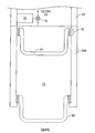
- FIG. 4 shows an alternative device to retrieve the nodal recorder.
- FIG. 1 An example nodal recorder geophysical survey system including a survey vessel 12 and on board recording systems 14 is shown in FIG. 1 .
- the vessel 12 moves along the surface of a body of water 11 such as a lake or the ocean.
- the recording system 14 typically includes equipment (none shown separately in FIG. 1 ) for actuating one or more energy sources 18A, 18B at selected times, for determining the geodetic position of the vessel 12 at any time, and for communicating, explained below, with nodal data recorders 10 deployed from the vessel 12 and positioned on the water bottom.
- the nodal recorders 10 are shown on the bottom of the body of water 11 after having been "launched” from the vessel 12 by a launcher or similar device to eject or deploy the nodal recorder 10 from the vessel 12 and cause it to enter the water 11.
- the geodetic position of the vessel 12 is determined at the time of launch of each nodal recorder 10, and navigation devices (explained below with reference to FIG. 3 ) in each nodal recorder 10 will cause the nodal recorder 10 to follow a selected path 13 as it travels from the water surface to the water bottom, so that when the recorder 10 reaches the water bottom (11A in FIG. 2 ), it is deployed at a selected geodetic position.
- FIG. 2 shows an example of the geophysical data sensing and recording components of one of the nodal recorders 10.
- the sensing recording components may be disposed in a pressure resistant housing 20.
- the geophysical sensors may include, for example, particle motion responsive sensors such as accelerometers or geophones, each preferably oriented along a mutually orthogonal direction from the other particle motion responsive sensors. The foregoing are shown in FIG. 2 at 32, 34 and 36.
- a pressure or pressure time gradient responsive sensor, such as a hydrophone is shown at 30 and is in pressure communication with the water 11 outside the housing 20.
- a transducer 22 disposed in the housing 20 and in signal communication with the water 11.
- the transducer 22 is also in signal communication with the central processor (CPU) 24.
- CPU central processor
- the CPU 24 Upon receipt of a command, for example, to begin recording, the CPU 24 will activate the recording device 26. Signals detected by the various sensors described above may be recorded, typically with reference to a selected time index. Such recording may continue until receipt of a subsequent command, such as through the water acoustically as shown at 42, to stop recording.
- Such command control may extend the life of batteries 28 disposed in the housing 20 and used to provide electrical power to operate the various devices inside the housing 20.
- the housing 20 can be coupled to a base plate 40 by an electrically operable latch 38.
- the housing 20, notwithstanding the contents therein, can be positively buoyant.
- the base plate 40 can be made from a dense material or have a core of dense materials, for example, degradable concrete, so that the baseplate 40 provides negative buoyancy to the entire nodal recorder 10 when the housing 20 is assembled to the baseplate 40.
- a command e.g., acoustic at 42
- the housing 20 may float to the surface for recovery by the vessel (12 in FIG. 1 ).
- the housing 20 may also include navigation devices 44, which will be explained in more detail with reference to FIG. 3 , and as explained above causes the nodal recorder 10 to traverse a selected path through the water 11 so that it is disposed at a selected geodetic position when it reaches the water bottom 11A.
- the housing 20 may include an electric or other type of selectively controllable brake 45 rotationally coupled to a turbine or propeller 47 disposed outside the housing 20.
- the brake 45 may be controlled by the CPU 24 so that the propeller 47 creates a selected drag on the housing 20. If the housing 20 exceeds a predetermined rate of descent through the water 11, the CPU can cause operation of the brake 45 to increase the drag.
- the rate of descent may be determined by measuring the rate of change of the external ambient water pressure, such as by using certain types of hydrophones for the hydrophone 30 seismic sensor.
- the navigation devices 44 may include two opposed pairs of fins 62, 64 disposed circumferentially about the exterior of the housing 20. In their neutral position the fins 62, 64 are parallel to the longitudinal axis of the housing 20 such that the housing 20 will fall substantially vertically through the water (11 in FIG. 1 ) and will resist reactive rotation caused by the propeller or turbine described above.
- the fins 62, 64 are rotatable about a line typically perpendicular to their longitudinal dimension, and are coupled to respective deflection motors, 58, 60, such that operation of deflection motor 58 will rotate the one opposed pair of fins 62. Corresponding operation of deflection motor 60 will rotate the other opposed pair of fins 64.
- a navigation central processor 56 (or in some examples such functionality may be programmed unto the CPU 24 in FIG. 2 ) such as a microprocessor may be initialized with the geodetic position of the nodal recorder at the time of launch or deployment of the nodal recorder.
- Such geodetic position may be obtained, for example by obtaining signals from a global positioning system satellite receiver (not shown) forming part of the recording unit (14 in FIG. 1 ).
- the initial programming may also include a selected or predetermined geodetic position of the nodal recorder 10 when it reaches the water bottom (11 in FIG. 2 ).
- the nodal recorder will have a final position that is determinable as a difference in coordinates between the initial position and the final position.
- the navigation devices may include a first Earth rate gyroscope 50 oriented along one axis normal to the longitudinal axis of the housing 20 (X gyro), and a second Earth rate gyroscope 52 oriented along an axis orthogonal to both of the foregoing (Y gyro).
- An accelerometer 54 may be oriented to determine deflection of the housing axis from vertical. The foregoing three measurements may be used in the central processor 56 to determine the net movement of the housing 20 in directions other than vertical from the original geodetic position.
- the central processor 56 may be programmed to operate the deflection motors 58, 60 to cause the fins 62, 64 to deflect the motion of the housing 20 to guide the housing toward the selected geodetic position on the water bottom. Suitable deflection of motion causes the housing 20 to move along a selected path (see 13 in FIG. 1 ) so that the final position of the nodal recorder (10 in FIG. 1 ) is the selected geodetic position. The foregoing maybe repeated for each such nodal recorder launched or deployed from the vessel (12 in FIG. 1 ).
- the gyroscopes 50, 52 may preferably be gimbal mounted on a frame (not shown) to enable the gyroscopes 50, 52 to remain in their respective orientations notwithstanding rotation of the housing 20.
- a non-limiting example of such a navigation system using gimbal mounted gyroscopes is described in U.S. Patent No. 4,611,405 issued to van Steenwyk .
- the recording unit 14 may send an acoustic command (detected by the transceiver 22 in FIG. 1 ) to initiate signal recording.
- the energy sources 18A, 18B which may be, for example, arrays of seismic air guns, may be actuated at selected times and the signals detected by the various sensors in the nodal recorders (see FIG. 2 ) may be recorded therein.
- the recoding unit 14 may send a command signal to release the latch (38 in FIG. 2 ) in each nodal recorder 10.
- the baseplates (40 in FIG. 2 ) will remain on the water bottom, but the remainder of each of the nodal recorders 10 will float to the surface, whereupon they may be recovered by the vessel.
- the CPU (24 in FIG. 2 ) may be programmed, after release of the latch (38 in FIG. 2 ) to cause the transceiver (22 in FIG. 2 ) to emit an acoustic signal to facilitate location of the nodal recorder 10 by the vessel 12 for recovery of the nodal recorder 10.
- the nodal recorder may be redeployed (launched) after installation of a replacement baseplate (40 in FIG. 2 ).
- the housing 20 may include a cylindrical extension 20A in which may be disposed a piston 74 sealed by o-rings 76 or the like.
- a high pressure gas source 70 may be disposed in the housing 20 and may be connected to the back side of the piston 74 through a solenoid valve 72.
- the valve 72 may open upon receipt of a signal from the central processor (24 in FIG. 2 ), thus pressurizing the back side of the piston 74 and causing it to move downwardly against water pressure.
- the piston 74 When the piston 74 is fully extended (shown as dotted lines) it may then exert reactive force against the water bottom, and at the same time define a gas filled chamber 73 inside the housing extension 20A. Dimensions of the housing extension 20A may be selected so that full extension of the piston 74 displaces enough water to cause the entire assembly (housing and housing extension) to be positively buoyant, thus floating the nodal recorder to the surface. When the piston 74 is in its retracted position, the entire assembly may be negatively buoyant to enable the nodal recorder to move to the water bottom.
- Nodal recording systems according to the invention do not require a planting frame or the use of a remotely operated vehicle to deploy the individual recorders. Accordingly, it is expected that efficiency of deployment, operation and recovery will be improved over nodal geophysical recorders known in the art prior to the present invention.
Description
- The invention relates generally to the field of marine geophysical data acquisition. More specifically, the invention relates to nodal data recorders that are self positioning on the bottom of a body of water.
- Marine geophysical data recording, in particular seismic data recording, may be performed using "nodal" recorders. Nodal recorders are self contained devices that are disposed at selected positions on the bottom of a body of water such as a lake or the ocean. An energy source deployed in the water is actuated at selected times and signals generated by sensors in the nodal recorders are stored in a recording device associated with each nodal recorder. SeaBed Geophysical AS, Transittg. 14 - 7042 Trondheim, Norway has developed a water bottom seismic node recording system called CASE® ("CAble less SEismic system"). The CASE system design is based on the concept of fully autonomous operation (i.e. no cables or surface telemetry). Autonomous operation is obtained by a design in which the unit is fully battery operated, with an internal capacity to record 2 millisecond samples of four-component seismic data (three orthogonal particle motion components and one pressure gradient component), substantially continuously up to 80 days. The CASE system includes a surface-to-node acoustic communications link to enable daily quality checking of the CASE nodal recording units throughout a data acquisition operation. The surface-to-node acoustic link also allows the system to be remotely queried, started, and stopped. Such function can also effectively extend the battery operating time on the CASE units. Deployment of the CASE units requires a remotely operated vehicle ("ROV") in water depths exceeding about 300 meters. In shallower water, a "planting frame" is used instead of the ROV. Practical applications for node acquisition begin with accuracy of placement. Using a planting frame or ROV as applicable, each node can be individually placed to within 1 meter of its intended geodetic position in a geophysical survey design. Such accuracy allows nodes to be used to particular advantage in applications involving uneven water bottom, environmentally sensitive areas, highly obstructed areas, and transition zones.
- Fairfield Industries Inc., 1111 Gillingham Lane Sugar Land, Texas 77478 is another company that has developed node-based data recording systems. The Fairfield Industries system is called the "Z system." The Z-system has been developed to acquire true "all-azimuth" seismic surveys. The nodal recorder technology can be used either to complement or, where applicable, replace traditional acquisition techniques (e.g., streamers or ocean bottom cables). Just as for the SeaBed Geophysical nodal recorders, deployment of the nodal devices made by Fairfield Industries requires use of a planting frame or ROV, depending on the water depth.
- Deep-water nodal recording technology is not yet a substitute for streamer (near surface) acquisition in large-scale exploration surveys. Node recording technology for the time being is focused on specific areas that essentially demand this type technology for exceptional quality imaging. This holds true both in deep water and the usually congested shallow water shelf areas, where the cable-free nodes can be deployed with relative ease.
- The main advantages of using node data recording systems can be summarized as follows. Node systems provide true all-azimuth capability, for quality data gathering to image beneath salt bodies, which substantially distort the seismic signal. Salt obstructions are widespread, particularly in the deep water Gulf of Mexico. 4-D, or time-lapse seismic, which is becoming increasingly necessary for effective reservoir monitoring and management, and can be used in deep-water fields. Infill areas are an excellent application for nodal recording technology. Platforms often are placed over the geographic center of a hydrocarbon producing field, and acquisition of seismic data around the field with streamers fails to address the void area. Node placement in the void area allows the streamer vessels to simultaneously record both streamer and node data, which can be merged in processing so the field is geophysically transparent. Because nodal seismic data recording units typically have a hydrophone and three geophones, the nodes are inherently multi-component, or 4-C, capable. Since nodal recorders can record converted waves (compressional to shear), they have the ability to record signals that pass through gas bearing formations. Such gas bearing formations make it difficult to acoustically illuminate the subsurface geology using conventional streamer seismic acquisition methodology.
- Notwithstanding the benefits of nodal acquisition and recording of geophysical survey data noted above, it is difficult and expensive to position each node at a selected geodetic location prior to a survey because of the need to individually position each node using a planting frame or ROV. It is also difficult and expensive to recover the nodal recorders after the survey is completed. There exists a need for improved nodal recording devices that can be more efficiently placed at the correct geodetic positions for a geophysical survey and recovered more easily after the survey is completed.
WO2007040411A ,WO0192918A US5894450A all disclose recording devices in accordance with the preamble of claim 1. - The invention consists in a nodal geophysical recorder, comprising:
- a housing;
- at least one geophysical sensor disposed within the housing;
- a recording device for recording signals detected by the at least one geophysical sensor;
- a navigation device configured to determine a path between an initial geodetic position of the housing and a selected geodetic position on the bottom of a body of water; and
- at least one deflector in signal communication with the navigation device and configured to cause the housing to move along the determined path after the housing is released into the body of water from the initial position;
- characterised by a drag inducing device operably associated with the housing and configured to control a rate of descent of the housing through the water.
- Other aspects and advantages of the invention will be apparent from the following description and the appended claims.
-
FIG. 1 shows a survey vessel deploying nodal recorders at the bottom of a body of water in a selected pattern to conduct a survey. -
FIG. 2 shows the recording parts of one of the nodal recorders shown inFIG. 1 . -
FIG. 3 shows an example navigation section of one of the nodal recorders. - FIG. 4 shows an alternative device to retrieve the nodal recorder.
- An example nodal recorder geophysical survey system including a
survey vessel 12 and onboard recording systems 14 is shown inFIG. 1 . Thevessel 12 moves along the surface of a body ofwater 11 such as a lake or the ocean. Therecording system 14 typically includes equipment (none shown separately inFIG. 1 ) for actuating one or more energy sources 18A, 18B at selected times, for determining the geodetic position of thevessel 12 at any time, and for communicating, explained below, withnodal data recorders 10 deployed from thevessel 12 and positioned on the water bottom. - The
nodal recorders 10 are shown on the bottom of the body ofwater 11 after having been "launched" from thevessel 12 by a launcher or similar device to eject or deploy thenodal recorder 10 from thevessel 12 and cause it to enter thewater 11. The geodetic position of thevessel 12 is determined at the time of launch of eachnodal recorder 10, and navigation devices (explained below with reference toFIG. 3 ) in eachnodal recorder 10 will cause thenodal recorder 10 to follow aselected path 13 as it travels from the water surface to the water bottom, so that when therecorder 10 reaches the water bottom (11A inFIG. 2 ), it is deployed at a selected geodetic position. -
FIG. 2 shows an example of the geophysical data sensing and recording components of one of thenodal recorders 10. The sensing recording components may be disposed in a pressureresistant housing 20. The geophysical sensors may include, for example, particle motion responsive sensors such as accelerometers or geophones, each preferably oriented along a mutually orthogonal direction from the other particle motion responsive sensors. The foregoing are shown inFIG. 2 at 32, 34 and 36. A pressure or pressure time gradient responsive sensor, such as a hydrophone, is shown at 30 and is in pressure communication with thewater 11 outside thehousing 20. Acentral processor 24, such as a microprocessor, controls operations of the sensors described above and arecording device 26. Commands may be received acoustically 42 such as from the vessel (12 inFIG. 1 ) and detected by atransducer 22 disposed in thehousing 20 and in signal communication with thewater 11. Thetransducer 22 is also in signal communication with the central processor (CPU) 24. Upon receipt of a command, for example, to begin recording, theCPU 24 will activate therecording device 26. Signals detected by the various sensors described above may be recorded, typically with reference to a selected time index. Such recording may continue until receipt of a subsequent command, such as through the water acoustically as shown at 42, to stop recording. Such command control may extend the life ofbatteries 28 disposed in thehousing 20 and used to provide electrical power to operate the various devices inside thehousing 20. - The
housing 20 can be coupled to abase plate 40 by an electricallyoperable latch 38. Thehousing 20, notwithstanding the contents therein, can be positively buoyant. Thebase plate 40 can be made from a dense material or have a core of dense materials, for example, degradable concrete, so that thebaseplate 40 provides negative buoyancy to the entirenodal recorder 10 when thehousing 20 is assembled to thebaseplate 40. When the survey is completed, for example, a command (e.g., acoustic at 42) may be communicated to theCPU 24 which will operate thelatch 38 to release thehousing 20 from thebaseplate 40. Thehousing 20 may float to the surface for recovery by the vessel (12 inFIG. 1 ). - The
housing 20 may also includenavigation devices 44, which will be explained in more detail with reference toFIG. 3 , and as explained above causes thenodal recorder 10 to traverse a selected path through thewater 11 so that it is disposed at a selected geodetic position when it reaches thewater bottom 11A. - In some examples, the
housing 20 may include an electric or other type of selectivelycontrollable brake 45 rotationally coupled to a turbine orpropeller 47 disposed outside thehousing 20. Thebrake 45 may be controlled by theCPU 24 so that thepropeller 47 creates a selected drag on thehousing 20. If thehousing 20 exceeds a predetermined rate of descent through thewater 11, the CPU can cause operation of thebrake 45 to increase the drag. The rate of descent may be determined by measuring the rate of change of the external ambient water pressure, such as by using certain types of hydrophones for thehydrophone 30 seismic sensor. - An example of
navigation devices 44 is shown in more detail inFIG. 3 . Thenavigation devices 44 may include two opposed pairs offins housing 20. In their neutral position thefins housing 20 such that thehousing 20 will fall substantially vertically through the water (11 inFIG. 1 ) and will resist reactive rotation caused by the propeller or turbine described above. Thefins deflection motor 58 will rotate the one opposed pair offins 62. Corresponding operation ofdeflection motor 60 will rotate the other opposed pair offins 64. - A navigation central processor 56 (or in some examples such functionality may be programmed unto the
CPU 24 inFIG. 2 ) such as a microprocessor may be initialized with the geodetic position of the nodal recorder at the time of launch or deployment of the nodal recorder. Such geodetic position may be obtained, for example by obtaining signals from a global positioning system satellite receiver (not shown) forming part of the recording unit (14 inFIG. 1 ). The initial programming may also include a selected or predetermined geodetic position of thenodal recorder 10 when it reaches the water bottom (11 inFIG. 2 ). Thus, the nodal recorder will have a final position that is determinable as a difference in coordinates between the initial position and the final position. The navigation devices may include a firstEarth rate gyroscope 50 oriented along one axis normal to the longitudinal axis of the housing 20 (X gyro), and a secondEarth rate gyroscope 52 oriented along an axis orthogonal to both of the foregoing (Y gyro). Anaccelerometer 54 may be oriented to determine deflection of the housing axis from vertical. The foregoing three measurements may be used in thecentral processor 56 to determine the net movement of thehousing 20 in directions other than vertical from the original geodetic position. Thecentral processor 56 may be programmed to operate thedeflection motors fins housing 20 to guide the housing toward the selected geodetic position on the water bottom. Suitable deflection of motion causes thehousing 20 to move along a selected path (see 13 inFIG. 1 ) so that the final position of the nodal recorder (10 inFIG. 1 ) is the selected geodetic position. The foregoing maybe repeated for each such nodal recorder launched or deployed from the vessel (12 inFIG. 1 ). - The
gyroscopes gyroscopes housing 20. A non-limiting example of such a navigation system using gimbal mounted gyroscopes is described inU.S. Patent No. 4,611,405 issued to van Steenwyk . - Returning to
FIG. 1 , when all thenodal recorders 10 have been deployed, therecording unit 14 may send an acoustic command (detected by thetransceiver 22 inFIG. 1 ) to initiate signal recording. The energy sources 18A, 18B, which may be, for example, arrays of seismic air guns, may be actuated at selected times and the signals detected by the various sensors in the nodal recorders (seeFIG. 2 ) may be recorded therein. - After the survey is completed, the
recoding unit 14 may send a command signal to release the latch (38 inFIG. 2 ) in eachnodal recorder 10. The baseplates (40 inFIG. 2 ) will remain on the water bottom, but the remainder of each of thenodal recorders 10 will float to the surface, whereupon they may be recovered by the vessel. In some examples, the CPU (24 inFIG. 2 ) may be programmed, after release of the latch (38 inFIG. 2 ) to cause the transceiver (22 inFIG. 2 ) to emit an acoustic signal to facilitate location of thenodal recorder 10 by thevessel 12 for recovery of thenodal recorder 10. - The nodal recorder may be redeployed (launched) after installation of a replacement baseplate (40 in
FIG. 2 ). - An alternative device to recover the nodal recorder is shown schematically in FIG. 4. Instead of the baseplate (40 in
FIG. 2 ), thehousing 20 may include acylindrical extension 20A in which may be disposed apiston 74 sealed by o-rings 76 or the like. A highpressure gas source 70 may be disposed in thehousing 20 and may be connected to the back side of thepiston 74 through asolenoid valve 72. Thevalve 72 may open upon receipt of a signal from the central processor (24 inFIG. 2 ), thus pressurizing the back side of thepiston 74 and causing it to move downwardly against water pressure. When thepiston 74 is fully extended (shown as dotted lines) it may then exert reactive force against the water bottom, and at the same time define a gas filledchamber 73 inside thehousing extension 20A. Dimensions of thehousing extension 20A may be selected so that full extension of thepiston 74 displaces enough water to cause the entire assembly (housing and housing extension) to be positively buoyant, thus floating the nodal recorder to the surface. When thepiston 74 is in its retracted position, the entire assembly may be negatively buoyant to enable the nodal recorder to move to the water bottom. - Nodal recording systems according to the invention do not require a planting frame or the use of a remotely operated vehicle to deploy the individual recorders. Accordingly, it is expected that efficiency of deployment, operation and recovery will be improved over nodal geophysical recorders known in the art prior to the present invention.
Claims (13)
- A nodal geophysical recorder (10), comprising:a housing (20);at least one geophysical sensor (30, 32, 34, 36) disposed within the housing;a recording device (26) for recording signals detected by the at least one geophysical sensor;a navigation device (44) configured to determine a path between an initial geodetic position of the housing and a selected geodetic position on the bottom (11A) of a body of water (11); andat least one deflector (62, 64) in signal communication with the navigation device and configured to cause the housing to move along the determined path after the housing is released into the body of water from the initial position;characterised by a drag inducing device (47) operably associated with the housing and configured to control a rate of descent of the housing (20) through the water (11).
- The recorder (10) of claim 1, wherein the at least one geophysical sensor (30, 32, 34, 36) comprises a hydrophone.
- The recorder (10) of claim 1, wherein the at least one geophysical sensor (30, 32, 34, 36) comprises particle motion sensors.
- The recorder (10) of any of the preceding claims, wherein the navigation device (44) comprises:at least one gyroscope (50, 52);an accelerometer (54) configured to measured deflection of the housing (20) from vertical;a central processor (56) in signal communication with the at least one gyroscope and the at least one accelerometer, the central processor configured to determine movement of the housing other than vertical, the central processor configured to operate the at least one deflector (62, 64) to cause the determined movement to follow the determined path.
- The recorder (10) of any of the preceding claims, further comprising a transducer (22) in signal communication with the recording device (26), the transducer configured to detect commands (42) transmitted through the water (11).
- The recorder (10) of claim 5, wherein the commands (42) include an instruction to initiate recording of signals detected by the at least one geophysical sensor (30, 32, 34, 36).
- The recorder (10) of any of the preceding claims, wherein a baseplate (40) is couplable to the housing (20) by a releasable latch (38), wherein the housing with baseplate attached is negatively buoyant, and wherein the housing detached from the baseplate is positively buoyant.
- The recorder (10) of claim 7, further comprising a transducer in signal communication with the latch (38), the transducer configured to detect a command (42) transmitted through the water (11), the command configured to release the latch.
- The recorder (10) of claim 8, wherein the transducer is configured to emit a signal into the water (11) to facilitate location of the housing (20) upon floatation of the housing to the water surface.
- The recorder (10) of any of claims 1 to 6, wherein the housing (20) comprises a piston (74) slidably disposed therein and coupled to a selectively controllable source (70) of pressurized gas, the gas source and piston configured such that application of gas to the piston cause motion thereof against water (11) and will increase a gas filled volume of the housing (20) such that the housing becomes positively buoyant.
- The recorder (10) of claim 10, further comprising a solenoid operated valve (72) configured to release the pressurized gas upon receipt of a signal.
- The recorder (10) of any of the preceding claims, wherein the drag inducing device (47) creates a selected drag on the housing (20).
- The recorder (10) of any of the preceding claims, wherein the drag inducing device (47) comprises a turbine or propeller disposed outside the housing (20) and the housing further includes a brake (45) rotationally coupled to the turbine or propeller, wherein operation of the brake increases the drag on the housing created by the turbine or propeller.
Applications Claiming Priority (1)
| Application Number | Priority Date | Filing Date | Title |
|---|---|---|---|
| US12/661,664 US20110228635A1 (en) | 2010-03-22 | 2010-03-22 | Self-positioning nodal geophysical recorder |
Publications (2)
| Publication Number | Publication Date |
|---|---|
| EP2372402A1 EP2372402A1 (en) | 2011-10-05 |
| EP2372402B1 true EP2372402B1 (en) | 2013-06-19 |
Family
ID=44117319
Family Applications (1)
| Application Number | Title | Priority Date | Filing Date |
|---|---|---|---|
| EP11158115.3A Not-in-force EP2372402B1 (en) | 2010-03-22 | 2011-03-14 | Self-Positioning Nodal Geophysical Recorder |
Country Status (3)
| Country | Link |
|---|---|
| US (1) | US20110228635A1 (en) |
| EP (1) | EP2372402B1 (en) |
| AU (2) | AU2011200891A1 (en) |
Families Citing this family (10)
| Publication number | Priority date | Publication date | Assignee | Title |
|---|---|---|---|---|
| EP2664945B1 (en) * | 2012-05-15 | 2015-07-08 | The Boeing Company | Unattended ground sensors |
| US9383471B2 (en) * | 2012-09-14 | 2016-07-05 | Cgg Services Sa | Method and underwater node for seismic survey |
| US9547095B2 (en) | 2012-12-19 | 2017-01-17 | Westerngeco L.L.C. | MEMS-based rotation sensor for seismic applications and sensor units having same |
| FR3000015B1 (en) * | 2012-12-20 | 2015-09-11 | Cggveritas Services Sa | AUTONOMOUS SUBMARINE VEHICLE FOR MARINE SEISMIC STUDIES |
| US10670759B2 (en) * | 2015-08-26 | 2020-06-02 | Conocophillips Company | Nodal hybrid gather |
| US10132947B2 (en) | 2015-10-19 | 2018-11-20 | Pgs Geophysical As | Marine data acquisition node |
| WO2017091480A1 (en) * | 2015-11-23 | 2017-06-01 | Westerngeco Llc | Gradient-based 4d seabed acquisition positioning |
| NO342823B1 (en) * | 2016-10-19 | 2018-08-13 | Polarcus Dmcc | Positioning of seismic equipment |
| CN107621655B (en) * | 2017-08-29 | 2020-06-02 | 电子科技大学 | Three-dimensional data fault enhancement method based on DoS filtering |
| GB2579615B (en) * | 2018-12-06 | 2020-12-23 | Equinor Energy As | Data acquisition method and system |
Citations (1)
| Publication number | Priority date | Publication date | Assignee | Title |
|---|---|---|---|---|
| US20030075096A1 (en) * | 2001-09-28 | 2003-04-24 | Leonard Kenneth J. | Variable buoyancy apparatus for controlling the movement of an object in water |
Family Cites Families (10)
| Publication number | Priority date | Publication date | Assignee | Title |
|---|---|---|---|---|
| US3812922A (en) * | 1969-08-06 | 1974-05-28 | B Stechler | Deep ocean mining, mineral harvesting and salvage vehicle |
| US4611405A (en) | 1981-08-17 | 1986-09-16 | Applied Technologies Associates | High speed well surveying |
| US5189642A (en) * | 1991-09-10 | 1993-02-23 | Chevron Research And Technology Company | Seafloor seismic recorder |
| US5894450A (en) * | 1997-04-15 | 1999-04-13 | Massachusetts Institute Of Technology | Mobile underwater arrays |
| US6657921B1 (en) * | 2000-05-31 | 2003-12-02 | Westerngeco Llc | Marine seismic sensor deployment system including reconfigurable sensor housings |
| US6951138B1 (en) * | 2000-11-01 | 2005-10-04 | Westerngeco L.L.C. | Method and apparatus for an ocean bottom seismic acquisition technique |
| US7310287B2 (en) * | 2003-05-30 | 2007-12-18 | Fairfield Industries Incorporated | Method and apparatus for seismic data acquisition |
| NO20054604L (en) * | 2005-10-06 | 2007-04-10 | Vidar Hovland | Deep-water discharge unit, especially in the form of a node |
| US7648105B2 (en) * | 2006-12-26 | 2010-01-19 | Airborne Systems North America Of Nj Inc. | Deployment brake release for a parachute |
| US8079546B2 (en) * | 2009-06-18 | 2011-12-20 | The Charles Stark Draper Laboratory, Inc. | Samara wing |
-
2010
- 2010-03-22 US US12/661,664 patent/US20110228635A1/en not_active Abandoned
-
2011
- 2011-02-28 AU AU2011200891A patent/AU2011200891A1/en not_active Abandoned
- 2011-03-14 EP EP11158115.3A patent/EP2372402B1/en not_active Not-in-force
-
2016
- 2016-05-10 AU AU2016203013A patent/AU2016203013B2/en not_active Ceased
Patent Citations (1)
| Publication number | Priority date | Publication date | Assignee | Title |
|---|---|---|---|---|
| US20030075096A1 (en) * | 2001-09-28 | 2003-04-24 | Leonard Kenneth J. | Variable buoyancy apparatus for controlling the movement of an object in water |
Also Published As
| Publication number | Publication date |
|---|---|
| EP2372402A1 (en) | 2011-10-05 |
| AU2016203013B2 (en) | 2017-09-14 |
| AU2011200891A1 (en) | 2011-10-06 |
| US20110228635A1 (en) | 2011-09-22 |
| AU2016203013A1 (en) | 2016-06-02 |
Similar Documents
| Publication | Publication Date | Title |
|---|---|---|
| AU2016203013B2 (en) | Self-positioning nodal geophysical recorder | |
| US9081119B2 (en) | Underseas seismic acquisition | |
| US8767505B2 (en) | In-sea power generation for marine seismic operations | |
| JP4354686B2 (en) | A system aimed at collecting seismic data of seabed formations using a submarine seismic data collection station. | |
| EP2943814B1 (en) | Simultaneous shooting nodal acquisition seismic survey methods | |
| US6657921B1 (en) | Marine seismic sensor deployment system including reconfigurable sensor housings | |
| AU2012357114B2 (en) | Water-coupled underwater node for seismic surveys | |
| CA2581193C (en) | Method and apparatus for seismic data acquisition | |
| US10514473B2 (en) | Seabed coupling plate for an ocean bottom seismic node | |
| US20140078861A1 (en) | Method and underwater node for seismic survey | |
| EP2539742A2 (en) | Seismic data acquisition using self-propelled underwater vehicles | |
| US20140362661A1 (en) | Unmanned vehicle-based seismic surveying | |
| WO2013045666A1 (en) | Underwater node for seismic surveys | |
| US10120087B2 (en) | Method and system with low-frequency seismic source | |
| US20180259666A1 (en) | Marine mixed-spread system and method for data acquisition | |
| US11079506B2 (en) | Multicomponent streamer | |
| US20190317236A1 (en) | Autonomous Marine Survey Nodes | |
| WO2017063985A1 (en) | Multi component sensor device for point measurements on the seabed during seismic surveys | |
| Flueh et al. | Options for multi-component seismic data acquisition in deep water | |
| de Kok | Directions in ocean-bottom surveying | |
| Khan et al. | Cutting-edge marine seismic technologies—Some novel approaches to acquiring 3D seismic data in a complex marine environment | |
| WO2017172504A1 (en) | Marine seismic acquisition system |
Legal Events
| Date | Code | Title | Description |
|---|---|---|---|
| PUAI | Public reference made under article 153(3) epc to a published international application that has entered the european phase |
Free format text: ORIGINAL CODE: 0009012 |
|
| AK | Designated contracting states |
Kind code of ref document: A1 Designated state(s): AL AT BE BG CH CY CZ DE DK EE ES FI FR GB GR HR HU IE IS IT LI LT LU LV MC MK MT NL NO PL PT RO RS SE SI SK SM TR |
|
| AX | Request for extension of the european patent |
Extension state: BA ME |
|
| 17P | Request for examination filed |
Effective date: 20120120 |
|
| 17Q | First examination report despatched |
Effective date: 20120525 |
|
| GRAP | Despatch of communication of intention to grant a patent |
Free format text: ORIGINAL CODE: EPIDOSNIGR1 |
|
| GRAS | Grant fee paid |
Free format text: ORIGINAL CODE: EPIDOSNIGR3 |
|
| GRAA | (expected) grant |
Free format text: ORIGINAL CODE: 0009210 |
|
| AK | Designated contracting states |
Kind code of ref document: B1 Designated state(s): AL AT BE BG CH CY CZ DE DK EE ES FI FR GB GR HR HU IE IS IT LI LT LU LV MC MK MT NL NO PL PT RO RS SE SI SK SM TR |
|
| REG | Reference to a national code |
Ref country code: GB Ref legal event code: FG4D |
|
| REG | Reference to a national code |
Ref country code: CH Ref legal event code: EP |
|
| REG | Reference to a national code |
Ref country code: AT Ref legal event code: REF Ref document number: 617950 Country of ref document: AT Kind code of ref document: T Effective date: 20130715 |
|
| REG | Reference to a national code |
Ref country code: IE Ref legal event code: FG4D |
|
| REG | Reference to a national code |
Ref country code: NO Ref legal event code: T2 Effective date: 20130619 |
|
| REG | Reference to a national code |
Ref country code: DE Ref legal event code: R096 Ref document number: 602011002045 Country of ref document: DE Effective date: 20130829 |
|
| PG25 | Lapsed in a contracting state [announced via postgrant information from national office to epo] |
Ref country code: GR Free format text: LAPSE BECAUSE OF FAILURE TO SUBMIT A TRANSLATION OF THE DESCRIPTION OR TO PAY THE FEE WITHIN THE PRESCRIBED TIME-LIMIT Effective date: 20130920 Ref country code: FI Free format text: LAPSE BECAUSE OF FAILURE TO SUBMIT A TRANSLATION OF THE DESCRIPTION OR TO PAY THE FEE WITHIN THE PRESCRIBED TIME-LIMIT Effective date: 20130619 Ref country code: SE Free format text: LAPSE BECAUSE OF FAILURE TO SUBMIT A TRANSLATION OF THE DESCRIPTION OR TO PAY THE FEE WITHIN THE PRESCRIBED TIME-LIMIT Effective date: 20130619 Ref country code: ES Free format text: LAPSE BECAUSE OF FAILURE TO SUBMIT A TRANSLATION OF THE DESCRIPTION OR TO PAY THE FEE WITHIN THE PRESCRIBED TIME-LIMIT Effective date: 20130930 Ref country code: SI Free format text: LAPSE BECAUSE OF FAILURE TO SUBMIT A TRANSLATION OF THE DESCRIPTION OR TO PAY THE FEE WITHIN THE PRESCRIBED TIME-LIMIT Effective date: 20130619 Ref country code: LT Free format text: LAPSE BECAUSE OF FAILURE TO SUBMIT A TRANSLATION OF THE DESCRIPTION OR TO PAY THE FEE WITHIN THE PRESCRIBED TIME-LIMIT Effective date: 20130619 |
|
| REG | Reference to a national code |
Ref country code: AT Ref legal event code: MK05 Ref document number: 617950 Country of ref document: AT Kind code of ref document: T Effective date: 20130619 |
|
| REG | Reference to a national code |
Ref country code: LT Ref legal event code: MG4D |
|
| PG25 | Lapsed in a contracting state [announced via postgrant information from national office to epo] |
Ref country code: RS Free format text: LAPSE BECAUSE OF FAILURE TO SUBMIT A TRANSLATION OF THE DESCRIPTION OR TO PAY THE FEE WITHIN THE PRESCRIBED TIME-LIMIT Effective date: 20130619 Ref country code: HR Free format text: LAPSE BECAUSE OF FAILURE TO SUBMIT A TRANSLATION OF THE DESCRIPTION OR TO PAY THE FEE WITHIN THE PRESCRIBED TIME-LIMIT Effective date: 20130619 Ref country code: BG Free format text: LAPSE BECAUSE OF FAILURE TO SUBMIT A TRANSLATION OF THE DESCRIPTION OR TO PAY THE FEE WITHIN THE PRESCRIBED TIME-LIMIT Effective date: 20130919 |
|
| REG | Reference to a national code |
Ref country code: NL Ref legal event code: VDEP Effective date: 20130619 |
|
| PG25 | Lapsed in a contracting state [announced via postgrant information from national office to epo] |
Ref country code: LV Free format text: LAPSE BECAUSE OF FAILURE TO SUBMIT A TRANSLATION OF THE DESCRIPTION OR TO PAY THE FEE WITHIN THE PRESCRIBED TIME-LIMIT Effective date: 20130619 |
|
| PG25 | Lapsed in a contracting state [announced via postgrant information from national office to epo] |
Ref country code: CZ Free format text: LAPSE BECAUSE OF FAILURE TO SUBMIT A TRANSLATION OF THE DESCRIPTION OR TO PAY THE FEE WITHIN THE PRESCRIBED TIME-LIMIT Effective date: 20130619 Ref country code: CY Free format text: LAPSE BECAUSE OF FAILURE TO SUBMIT A TRANSLATION OF THE DESCRIPTION OR TO PAY THE FEE WITHIN THE PRESCRIBED TIME-LIMIT Effective date: 20130619 Ref country code: EE Free format text: LAPSE BECAUSE OF FAILURE TO SUBMIT A TRANSLATION OF THE DESCRIPTION OR TO PAY THE FEE WITHIN THE PRESCRIBED TIME-LIMIT Effective date: 20130619 Ref country code: PT Free format text: LAPSE BECAUSE OF FAILURE TO SUBMIT A TRANSLATION OF THE DESCRIPTION OR TO PAY THE FEE WITHIN THE PRESCRIBED TIME-LIMIT Effective date: 20131021 Ref country code: AT Free format text: LAPSE BECAUSE OF FAILURE TO SUBMIT A TRANSLATION OF THE DESCRIPTION OR TO PAY THE FEE WITHIN THE PRESCRIBED TIME-LIMIT Effective date: 20130619 Ref country code: BE Free format text: LAPSE BECAUSE OF FAILURE TO SUBMIT A TRANSLATION OF THE DESCRIPTION OR TO PAY THE FEE WITHIN THE PRESCRIBED TIME-LIMIT Effective date: 20130619 Ref country code: SK Free format text: LAPSE BECAUSE OF FAILURE TO SUBMIT A TRANSLATION OF THE DESCRIPTION OR TO PAY THE FEE WITHIN THE PRESCRIBED TIME-LIMIT Effective date: 20130619 Ref country code: IS Free format text: LAPSE BECAUSE OF FAILURE TO SUBMIT A TRANSLATION OF THE DESCRIPTION OR TO PAY THE FEE WITHIN THE PRESCRIBED TIME-LIMIT Effective date: 20131019 |
|
| PG25 | Lapsed in a contracting state [announced via postgrant information from national office to epo] |
Ref country code: NL Free format text: LAPSE BECAUSE OF FAILURE TO SUBMIT A TRANSLATION OF THE DESCRIPTION OR TO PAY THE FEE WITHIN THE PRESCRIBED TIME-LIMIT Effective date: 20130619 Ref country code: RO Free format text: LAPSE BECAUSE OF FAILURE TO SUBMIT A TRANSLATION OF THE DESCRIPTION OR TO PAY THE FEE WITHIN THE PRESCRIBED TIME-LIMIT Effective date: 20130619 Ref country code: PL Free format text: LAPSE BECAUSE OF FAILURE TO SUBMIT A TRANSLATION OF THE DESCRIPTION OR TO PAY THE FEE WITHIN THE PRESCRIBED TIME-LIMIT Effective date: 20130619 |
|
| PLBE | No opposition filed within time limit |
Free format text: ORIGINAL CODE: 0009261 |
|
| STAA | Information on the status of an ep patent application or granted ep patent |
Free format text: STATUS: NO OPPOSITION FILED WITHIN TIME LIMIT |
|
| PG25 | Lapsed in a contracting state [announced via postgrant information from national office to epo] |
Ref country code: DK Free format text: LAPSE BECAUSE OF FAILURE TO SUBMIT A TRANSLATION OF THE DESCRIPTION OR TO PAY THE FEE WITHIN THE PRESCRIBED TIME-LIMIT Effective date: 20130619 |
|
| 26N | No opposition filed |
Effective date: 20140320 |
|
| PG25 | Lapsed in a contracting state [announced via postgrant information from national office to epo] |
Ref country code: IT Free format text: LAPSE BECAUSE OF FAILURE TO SUBMIT A TRANSLATION OF THE DESCRIPTION OR TO PAY THE FEE WITHIN THE PRESCRIBED TIME-LIMIT Effective date: 20130619 |
|
| REG | Reference to a national code |
Ref country code: DE Ref legal event code: R097 Ref document number: 602011002045 Country of ref document: DE Effective date: 20140320 |
|
| REG | Reference to a national code |
Ref country code: DE Ref legal event code: R119 Ref document number: 602011002045 Country of ref document: DE |
|
| PG25 | Lapsed in a contracting state [announced via postgrant information from national office to epo] |
Ref country code: LU Free format text: LAPSE BECAUSE OF FAILURE TO SUBMIT A TRANSLATION OF THE DESCRIPTION OR TO PAY THE FEE WITHIN THE PRESCRIBED TIME-LIMIT Effective date: 20140314 |
|
| REG | Reference to a national code |
Ref country code: CH Ref legal event code: PL |
|
| REG | Reference to a national code |
Ref country code: IE Ref legal event code: MM4A |
|
| REG | Reference to a national code |
Ref country code: DE Ref legal event code: R119 Ref document number: 602011002045 Country of ref document: DE Effective date: 20141001 |
|
| PG25 | Lapsed in a contracting state [announced via postgrant information from national office to epo] |
Ref country code: DE Free format text: LAPSE BECAUSE OF NON-PAYMENT OF DUE FEES Effective date: 20141001 Ref country code: CH Free format text: LAPSE BECAUSE OF NON-PAYMENT OF DUE FEES Effective date: 20140331 Ref country code: LI Free format text: LAPSE BECAUSE OF NON-PAYMENT OF DUE FEES Effective date: 20140331 Ref country code: IE Free format text: LAPSE BECAUSE OF NON-PAYMENT OF DUE FEES Effective date: 20140314 |
|
| PG25 | Lapsed in a contracting state [announced via postgrant information from national office to epo] |
Ref country code: MT Free format text: LAPSE BECAUSE OF FAILURE TO SUBMIT A TRANSLATION OF THE DESCRIPTION OR TO PAY THE FEE WITHIN THE PRESCRIBED TIME-LIMIT Effective date: 20130619 |
|
| REG | Reference to a national code |
Ref country code: FR Ref legal event code: PLFP Year of fee payment: 6 |
|
| PG25 | Lapsed in a contracting state [announced via postgrant information from national office to epo] |
Ref country code: SM Free format text: LAPSE BECAUSE OF FAILURE TO SUBMIT A TRANSLATION OF THE DESCRIPTION OR TO PAY THE FEE WITHIN THE PRESCRIBED TIME-LIMIT Effective date: 20130619 |
|
| PG25 | Lapsed in a contracting state [announced via postgrant information from national office to epo] |
Ref country code: MC Free format text: LAPSE BECAUSE OF FAILURE TO SUBMIT A TRANSLATION OF THE DESCRIPTION OR TO PAY THE FEE WITHIN THE PRESCRIBED TIME-LIMIT Effective date: 20130619 |
|
| PG25 | Lapsed in a contracting state [announced via postgrant information from national office to epo] |
Ref country code: HU Free format text: LAPSE BECAUSE OF FAILURE TO SUBMIT A TRANSLATION OF THE DESCRIPTION OR TO PAY THE FEE WITHIN THE PRESCRIBED TIME-LIMIT; INVALID AB INITIO Effective date: 20110314 Ref country code: TR Free format text: LAPSE BECAUSE OF FAILURE TO SUBMIT A TRANSLATION OF THE DESCRIPTION OR TO PAY THE FEE WITHIN THE PRESCRIBED TIME-LIMIT Effective date: 20130619 |
|
| REG | Reference to a national code |
Ref country code: FR Ref legal event code: PLFP Year of fee payment: 7 |
|
| REG | Reference to a national code |
Ref country code: FR Ref legal event code: PLFP Year of fee payment: 8 |
|
| PG25 | Lapsed in a contracting state [announced via postgrant information from national office to epo] |
Ref country code: MK Free format text: LAPSE BECAUSE OF FAILURE TO SUBMIT A TRANSLATION OF THE DESCRIPTION OR TO PAY THE FEE WITHIN THE PRESCRIBED TIME-LIMIT Effective date: 20130619 |
|
| PG25 | Lapsed in a contracting state [announced via postgrant information from national office to epo] |
Ref country code: AL Free format text: LAPSE BECAUSE OF FAILURE TO SUBMIT A TRANSLATION OF THE DESCRIPTION OR TO PAY THE FEE WITHIN THE PRESCRIBED TIME-LIMIT Effective date: 20130619 |
|
| PGFP | Annual fee paid to national office [announced via postgrant information from national office to epo] |
Ref country code: GB Payment date: 20200327 Year of fee payment: 10 Ref country code: NO Payment date: 20200327 Year of fee payment: 10 |
|
| PGFP | Annual fee paid to national office [announced via postgrant information from national office to epo] |
Ref country code: FR Payment date: 20200325 Year of fee payment: 10 |
|
| REG | Reference to a national code |
Ref country code: NO Ref legal event code: MMEP |
|
| GBPC | Gb: european patent ceased through non-payment of renewal fee |
Effective date: 20210314 |
|
| PG25 | Lapsed in a contracting state [announced via postgrant information from national office to epo] |
Ref country code: NO Free format text: LAPSE BECAUSE OF NON-PAYMENT OF DUE FEES Effective date: 20210331 Ref country code: GB Free format text: LAPSE BECAUSE OF NON-PAYMENT OF DUE FEES Effective date: 20210314 Ref country code: FR Free format text: LAPSE BECAUSE OF NON-PAYMENT OF DUE FEES Effective date: 20210331 |