EP2372254A1 - Assembly for mounting a venting duct in a housing wall of a household appliance and range comprising such an assembly - Google Patents
Assembly for mounting a venting duct in a housing wall of a household appliance and range comprising such an assembly Download PDFInfo
- Publication number
- EP2372254A1 EP2372254A1 EP10003438A EP10003438A EP2372254A1 EP 2372254 A1 EP2372254 A1 EP 2372254A1 EP 10003438 A EP10003438 A EP 10003438A EP 10003438 A EP10003438 A EP 10003438A EP 2372254 A1 EP2372254 A1 EP 2372254A1
- Authority
- EP
- European Patent Office
- Prior art keywords
- assembly
- connector member
- outlet
- venting duct
- housing wall
- Prior art date
- Legal status (The legal status is an assumption and is not a legal conclusion. Google has not performed a legal analysis and makes no representation as to the accuracy of the status listed.)
- Granted
Links
- 238000013022 venting Methods 0.000 title claims abstract description 57
- 239000003517 fume Substances 0.000 claims description 12
- 229910052751 metal Inorganic materials 0.000 claims description 4
- 239000002184 metal Substances 0.000 claims description 4
- 239000002991 molded plastic Substances 0.000 claims description 4
- 229910052782 aluminium Inorganic materials 0.000 claims description 2
- XAGFODPZIPBFFR-UHFFFAOYSA-N aluminium Chemical compound [Al] XAGFODPZIPBFFR-UHFFFAOYSA-N 0.000 claims description 2
- 239000000463 material Substances 0.000 description 4
- 229910001220 stainless steel Inorganic materials 0.000 description 3
- 239000010935 stainless steel Substances 0.000 description 3
- 230000001419 dependent effect Effects 0.000 description 1
- 239000007789 gas Substances 0.000 description 1
- 239000004033 plastic Substances 0.000 description 1
Images


Classifications
-
- F—MECHANICAL ENGINEERING; LIGHTING; HEATING; WEAPONS; BLASTING
- F24—HEATING; RANGES; VENTILATING
- F24C—DOMESTIC STOVES OR RANGES ; DETAILS OF DOMESTIC STOVES OR RANGES, OF GENERAL APPLICATION
- F24C15/00—Details
- F24C15/20—Removing cooking fumes
- F24C15/2007—Removing cooking fumes from oven cavities
Definitions
- the present invention relates to an assembly for mounting a venting duct in a housing wall, a base plate or cover frame of a household appliance and to a range or a hob comprising such an assembly.
- venting ducts are provided for the removal of vapors from the oven muffle.
- EP 0 834 702 B1 there is known a device for removing fumes from an oven muffle, which device comprises a flexible fume tube which is connected to the oven muffle and a holding device for mounting the outlet end of the fume tube.
- the outlet end of the connector member and the mounting portion of the outlet member are adapted for snap-fit connection, that is these two members are designed such that one of the two members has at least one projection which in the assembled state projects into a corresponding recess or depression of the respective other member, wherein during assembling the two members at least one of the two members is temporarily deformed until the projection snaps into the corresponding recess or depression that is provided at the respective other member.
- the mounting of the assembly can be done simply by pushing these two parts together, that is fast and efficiently and without the need for any specific tools.
- the connector member comprising biasing means, which in the assembled state rests resiliently against the inner side of the housing wall or the lower surface of the base plate or the cover frame, the connector member and hence the entire assembly is permanently and securely held at the housing wall of the household appliance irrespective of the thickness of the housing wall. In this manner, the assembly is fixedly held and compensates tolerances in the thickness of the housing wall of the household appliance.
- the design of the assembly suggested herein allows to use one and the same type of assembly for different housing types of the household appliance, such as for different models of a household appliance, such as a range or a hob, which is offered with different housing, base plate or frame materials such as a stainless steel and enameled metal, wherein the stainless steel housing provides for thinner housing walls than the enameled metal housing.
- venting duct is a fume tube for connection to an oven muffle, such as in an electric or gas fired range or in a microwave oven
- the assembly also can be applied to advantage in other household appliances, such as refrigerators or the like.
- the biasing means can comprise a plurality of resilient tabs, which laterally project from the connector member. While such tabs could be spring-loaded members, resiliency of the tabs preferably is provided by the selection of the material and geometry of the connector member.
- a particularly cost-effective solution consists in designing the connector member as a molded plastic member, wherein the resilient tabs are formed as an integral part of the connector member.
- the abutment member comprises a rim which extends along the circumference of the mounting portion of the outlet member. Since the outlet member usually is mounted within an opening of the housing wall of the household appliance, which opening is slightly larger than the cross-section of the mounting portion, such a circumferential rim, in addition to providing for an abutment surface, serves the double purpose of hiding the gap which is formed between the inner wall of the opening in the housing wall and the outer circumference of the mounting portion inserted therein.
- the inlet end of the connector member and the venting duct are provided with means for snap-fit connection between the connector member and the venting duct.
- providing for a snap-fit connection also between the connector member and the venting duct allows a quick and simple mounting operation, which does not require any specific mounting tools and also obviates the need to apply any separate fixing means to secure the connection, such as screws, clamps, brackets or the like.
- the connector member at its inlet end, can be provided with latch members for engaging respective latch surfaces, which are provided at the venting duct.
- the latch members in such embodiments can comprise resilient tabs which are provided in a circumferential wall of the connector member.
- the latch members can be formed by providing a generally V-shaped or U-shaped break-through in the wall of the connector member so as to provide for generally V-shaped or U-shaped resilient tabs, which at their tips comprise a latching projection, which, when sliding a venting duct above the inlet end of the connector member, engage a respective recess provided in the venting duct.
- the material of the venting duct will be selected in dependency of the type of household appliance in which the venting duct is to be used. Particularly, if the household appliance is a range and the venting duct thus is a fume tube via which hot fumes can be removed from the oven muffle, the venting duct preferably is a metal tube, such as an aluminum tube.
- the venting duct preferably comprises a section of flexible tubing.
- the respective recess provided in the venting duct may be a depression of a corrugated inner wall of the flexible tubing.
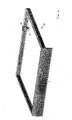
- the range preferably comprises a hob and a frame for mounting the hob, wherein the frame comprises an opening which is adapted to accommodate the mounting portion of the outlet member.
- FIG. 1 shows the terminal end of a venting duct 10, which may be a fume tube for venting fumes from an oven muffle (not shown).
- a venting duct 10 which may be a fume tube for venting fumes from an oven muffle (not shown).
- an outlet member 14 having a generally tubular mounting portion 18 which is inserted from the exterior side of the housing through a correspondingly shaped opening 20 provided in the housing wall 12.
- Outlet member 14 at its upper end comprises a venting outlet 22 which in the embodiment shown in the drawings further comprises a deflector 24 to impart a certain flow direction to the fumes exiting venting duct 10. Since in the embodiment shown in the drawings the mounting assembly is designed for use in a range wherein the outlet member is attached to the rear part of a hob frame 26 (see FIG. 4 ), deflector 24 is adapted to direct the fumes exiting the venting duct towards the front of the range, so that any fumes can be removed by an extractor hood as it often is provided above the hob.
- outlet member 14 comprises a circumferential rim 30 which is located at the upper end of the mounting portion 18 and which acts as an abutment member with which output member 14 abuts against the upper surface of the housing wall 12 when the outlet member is inserted into opening 20.
- connector member 16 which in the embodiment shown in the drawings is a molded plastic part, comprises an upper section which is adapted for engagement with the outlet member14 and with the lower side of housing wall 12, and further comprises a lower section which forms the inlet end of connector member 16 and which is adapted for connecting venting duct 10.
- the upper section of connector member 16, which constitutes the outlet end 32 of connector member 16 has an inner cross-section the shape of which corresponds to the outer cross-section of mounting portion 18 of outlet member 14.
- the inlet end 34 of connector member 16 has a circular cross-section, which corresponds to the inner cross-section of venting duct 10.
- outlet member 14 and connector member 16 are designed for snap-fit connection.
- mounting portion 18 is provided at its front and rear sides with a centrally located recess 36 for engagement with correspondingly located latching projections 38 provided at the inner front and rear sides of the outlet end 32 of connector member 16 (see also FIG. 3 ).
- connector member 16 at its upper end is provided with laterally projecting resilient tabs 40, which in the non-assembled state extend slightly upwards beyond the upper edge of the outlet end of connector member 16 and which in the assembled state bear against the lower side of housing wall 12.
- the mounting assembly thus can be used for different models of similar household appliances such as a range, which are manufactured for example either with a hob frame that is made of stainless steel or with an enameled hob frame.
- connector member 16 comprises latch members 42, which in the embodiment shown in FIGS. 1 to 3 are formed by providing a generally U-shaped recess 44 in the sidewall of the inlet end of connector member16, wherein there is provided a latching projection 46 at the tip of tabs 42.
- Venting duct 10 is provided with correspondingly located recesses 48, which accommodate the latching members 46 when the venting duct 10 is pushed over the inlet end 34 of connector member 16.
- a circumferential rim 50 which acts as stop for a venting duct that is slid onto the inlet end 34 of connector member 16.
- the present invention provides for a mounting assembly, by which a venting duct can be mounted in a particularly simple and rapid manner in a housing wall of a household appliance, and which yet provides for a secure and play-free mounting of the assembly to housing walls of varying thickness.
Landscapes
- Engineering & Computer Science (AREA)
- Chemical & Material Sciences (AREA)
- Combustion & Propulsion (AREA)
- Mechanical Engineering (AREA)
- General Engineering & Computer Science (AREA)
- Ventilation (AREA)
- Cookers (AREA)
Abstract
(a) an outlet member (14) comprising a venting outlet (22), a generally tubular mounting portion (18), and an abutment member (30) for abutment against the exterior side of said housing wall (12);
(b) a connector member (16) comprising an inlet end (34) adapted for fixing said venting duct (10), and an outlet end (32) adapted for attachment to the mounting portion (18) of the outlet member (14);
(c) wherein the outlet end (32) of said connector member (16) and the mounting portion (18) of said outlet member (14) are adapted for snap-fit connection, and
(e) said connector member (16) comprises biasing means (40) adapted to rest resiliently against the inner side of said housing wall (12) so as to exert a force which biases the connector member away from said housing wall.
Description
- The present invention relates to an assembly for mounting a venting duct in a housing wall, a base plate or cover frame of a household appliance and to a range or a hob comprising such an assembly.
- In ranges or ovens for preparing food often venting ducts are provided for the removal of vapors from the oven muffle.
- For example, from
EP 0 834 702 B1 there is known a device for removing fumes from an oven muffle, which device comprises a flexible fume tube which is connected to the oven muffle and a holding device for mounting the outlet end of the fume tube. - It is an object of the present invention to provide for an assembly for mounting a venting duct in a housing wall, a base plate or a cover frame of a household appliance which facilitates mounting of the venting duct and which thus allows an easy but yet fast and secure mounting of the venting duct. Furthermore, it is an object of the present invention to provide for an assembly for mounting a venting duct in a housing wall, a base plate or a cover frame of a household appliance, which allows secure mounting of venting ducts at differing thicknesses of the housing wall of the household appliance where the venting duct is to be mounted.
- In accordance with the present invention the above objects are solved by an assembly for mounting a venting duct in the housing wall, a base plate or a cover frame of a household appliance as it is defined in claim 1 and by a range as it is defined in claim 13.
- In accordance with the present invention the outlet end of the connector member and the mounting portion of the outlet member are adapted for snap-fit connection, that is these two members are designed such that one of the two members has at least one projection which in the assembled state projects into a corresponding recess or depression of the respective other member, wherein during assembling the two members at least one of the two members is temporarily deformed until the projection snaps into the corresponding recess or depression that is provided at the respective other member.
- With the outlet member and the connector being held together by snap-fit connection, the mounting of the assembly can be done simply by pushing these two parts together, that is fast and efficiently and without the need for any specific tools. With further the connector member comprising biasing means, which in the assembled state rests resiliently against the inner side of the housing wall or the lower surface of the base plate or the cover frame, the connector member and hence the entire assembly is permanently and securely held at the housing wall of the household appliance irrespective of the thickness of the housing wall. In this manner, the assembly is fixedly held and compensates tolerances in the thickness of the housing wall of the household appliance. Furthermore, the design of the assembly suggested herein allows to use one and the same type of assembly for different housing types of the household appliance, such as for different models of a household appliance, such as a range or a hob, which is offered with different housing, base plate or frame materials such as a stainless steel and enameled metal, wherein the stainless steel housing provides for thinner housing walls than the enameled metal housing.
- Preferred embodiments of the present invention are defined in the dependent claims.
- In particular, while in preferred embodiments the venting duct is a fume tube for connection to an oven muffle, such as in an electric or gas fired range or in a microwave oven, the assembly also can be applied to advantage in other household appliances, such as refrigerators or the like.
- The biasing means can comprise a plurality of resilient tabs, which laterally project from the connector member. While such tabs could be spring-loaded members, resiliency of the tabs preferably is provided by the selection of the material and geometry of the connector member. A particularly cost-effective solution consists in designing the connector member as a molded plastic member, wherein the resilient tabs are formed as an integral part of the connector member.
- Preferably, the abutment member comprises a rim which extends along the circumference of the mounting portion of the outlet member. Since the outlet member usually is mounted within an opening of the housing wall of the household appliance, which opening is slightly larger than the cross-section of the mounting portion, such a circumferential rim, in addition to providing for an abutment surface, serves the double purpose of hiding the gap which is formed between the inner wall of the opening in the housing wall and the outer circumference of the mounting portion inserted therein.
- In preferred embodiments the inlet end of the connector member and the venting duct are provided with means for snap-fit connection between the connector member and the venting duct. Thus, similarly as was the case for the mounting of the outlet member and the connector member, providing for a snap-fit connection also between the connector member and the venting duct allows a quick and simple mounting operation, which does not require any specific mounting tools and also obviates the need to apply any separate fixing means to secure the connection, such as screws, clamps, brackets or the like.
- In order to provide for a snap-fit connection between the connector member and the venting duct, the connector member, at its inlet end, can be provided with latch members for engaging respective latch surfaces, which are provided at the venting duct. The latch members in such embodiments can comprise resilient tabs which are provided in a circumferential wall of the connector member. For example, if the connector member is a molded plastic component, wherein the plastic material provides for a certain elasticity, the latch members can be formed by providing a generally V-shaped or U-shaped break-through in the wall of the connector member so as to provide for generally V-shaped or U-shaped resilient tabs, which at their tips comprise a latching projection, which, when sliding a venting duct above the inlet end of the connector member, engage a respective recess provided in the venting duct.
- The material of the venting duct will be selected in dependency of the type of household appliance in which the venting duct is to be used. Particularly, if the household appliance is a range and the venting duct thus is a fume tube via which hot fumes can be removed from the oven muffle, the venting duct preferably is a metal tube, such as an aluminum tube.
- In order to facilitate the mounting of the venting duct and also to provide for more flexibility of use of the venting duct, the venting duct preferably comprises a section of flexible tubing. In such case, the respective recess provided in the venting duct may be a depression of a corrugated inner wall of the flexible tubing. The assembly described above is of particular advantage when used in a range comprising such assembly in combination with an oven muffle or in a hob to be connected to an oven muffle of an oven and wherein the venting duct comprises a first end which is connected to the inlet end of the connector member and a second end which is connected to the oven muffle.
- While in such a range the output member could be provided in any part of the housing of the range, the range preferably comprises a hob and a frame for mounting the hob, wherein the frame comprises an opening which is adapted to accommodate the mounting portion of the outlet member.
- A preferred embodiment of the assembly suggested herein is described below by reference to the drawings, in which:
-
FIG. 1 is an exploded perspective view of the assembly in accordance with the present invention; -
FIG. 2 is a side view of the assembly shown inFIG. 1 when mounted; -
FIG. 3 is a sectional view of the arrangement shown inFIG. 2 ; and -
FIG. 4 is a perspective view of a hob frame at which there is mounted an assembly as shown inFIGS. 1 to 3 . -
FIG. 1 shows the terminal end of aventing duct 10, which may be a fume tube for venting fumes from an oven muffle (not shown). - In order to provide for an easy-to-assemble arrangement for providing for an outlet of the
venting duct 10 at ahousing wall 12 of a household appliance, such as a range or an oven, there is provided anoutlet member 14 having a generallytubular mounting portion 18 which is inserted from the exterior side of the housing through a correspondingly shaped opening 20 provided in thehousing wall 12.Outlet member 14 at its upper end comprises aventing outlet 22 which in the embodiment shown in the drawings further comprises adeflector 24 to impart a certain flow direction to the fumes exitingventing duct 10. Since in the embodiment shown in the drawings the mounting assembly is designed for use in a range wherein the outlet member is attached to the rear part of a hob frame 26 (seeFIG. 4 ),deflector 24 is adapted to direct the fumes exiting the venting duct towards the front of the range, so that any fumes can be removed by an extractor hood as it often is provided above the hob. - As is further shown in
FIGS. 1 to 3 ,outlet member 14 comprises acircumferential rim 30 which is located at the upper end of themounting portion 18 and which acts as an abutment member with whichoutput member 14 abuts against the upper surface of thehousing wall 12 when the outlet member is inserted into opening 20. - As is shown in
FIGS. 1 to 3 ,connector member 16, which in the embodiment shown in the drawings is a molded plastic part, comprises an upper section which is adapted for engagement with the outlet member14 and with the lower side ofhousing wall 12, and further comprises a lower section which forms the inlet end ofconnector member 16 and which is adapted for connectingventing duct 10. Thus, the upper section ofconnector member 16, which constitutes theoutlet end 32 ofconnector member 16 has an inner cross-section the shape of which corresponds to the outer cross-section ofmounting portion 18 ofoutlet member 14. In the embodiment shown in the drawings theinlet end 34 ofconnector member 16 has a circular cross-section, which corresponds to the inner cross-section ofventing duct 10. - In order to allow for a particularly quick and easy assembly of the individual components,
outlet member 14 andconnector member 16 are designed for snap-fit connection. To thisend mounting portion 18 is provided at its front and rear sides with a centrally locatedrecess 36 for engagement with correspondingly locatedlatching projections 38 provided at the inner front and rear sides of theoutlet end 32 of connector member 16 (see alsoFIG. 3 ). - In order to fixedly secure the mounting assembly at housing walls of varying thickness,
connector member 16 at its upper end is provided with laterally projectingresilient tabs 40, which in the non-assembled state extend slightly upwards beyond the upper edge of the outlet end ofconnector member 16 and which in the assembled state bear against the lower side ofhousing wall 12. The mounting assembly thus can be used for different models of similar household appliances such as a range, which are manufactured for example either with a hob frame that is made of stainless steel or with an enameled hob frame. - In order to provide for simple and quick attachment of the venting duct to the connector member, also the connector member and the venting duct are adapted for snap-fit connection. To this end,
connector member 16 compriseslatch members 42, which in the embodiment shown inFIGS. 1 to 3 are formed by providing a generallyU-shaped recess 44 in the sidewall of the inlet end of connector member16, wherein there is provided a latching projection 46 at the tip oftabs 42.Venting duct 10 is provided with correspondingly locatedrecesses 48, which accommodate the latching members 46 when theventing duct 10 is pushed over theinlet end 34 ofconnector member 16. - In the central region of
connector member 16 where the tubular inlet end merges into the outlet end there is provided acircumferential rim 50, which acts as stop for a venting duct that is slid onto theinlet end 34 ofconnector member 16. - As will be appreciated from the above description, the present invention provides for a mounting assembly, by which a venting duct can be mounted in a particularly simple and rapid manner in a housing wall of a household appliance, and which yet provides for a secure and play-free mounting of the assembly to housing walls of varying thickness.
-
- 10
- venting duct
- 12
- housing wall
- 14
- outlet member
- 16
- connector member
- 18
- mounting portion
- 20
- opening
- 22
- venting outlet
- 24
- deflector member
- 26
- hob frame
- 30
- abutment member
- 32
- outlet end
- 34
- inlet end
- 36
- recess
- 38
- latching projection
- 40
- biasing tab
- 42
- latch member
- 44
- recess
- 46
- latch surface
- 48
- recess
- 50
- stop
Claims (16)
- Assembly for mounting a venting duct (10) in a housing wall (12), in a base plate or in a cover frame of a household appliance, comprising:(a) an outlet member (14) comprising a venting outlet (22), a generally tubular mounting portion (18), and an abutment member (30) for abutment against the exterior side of said housing wall (12); and(b) a connector member (16) comprising an inlet end (34) adapted for fixing said venting duct (10), and an outlet end (32) adapted for attachment to the mounting portion (18) of the outlet member (14);
characterized in that(c) the outlet end (32) of said connector member (16) and the mounting portion (18) of said outlet member (14) are adapted for snap-fit connection, and(d) said connector member (16) comprises biasing means (40) adapted to rest resiliently against the inner side of said housing wall (12) so as to exert a force which biases the connector member away from said housing wall. - The assembly of claim 1, wherein said venting duct (10) is a fume tube for connection to an oven muffle.
- The assembly of claim 1 or 2, wherein said biasing means (40) comprises a plurality of resilient tabs laterally projecting from said connector member (16).
- The assembly of any one of the preceding claims, wherein, in order to provide for a snap-fit connection between said connector member (15) and said outlet member (14), said mounting portion (18) of the outlet member (14) comprises at least one recess (36) and said connector member (16) comprises a latching projection (38), which in the assembled state of the assembly projects into said recess.
- The assembly of claim 4, wherein said outlet member (14) has an oblong cross-section, and said recess (36) is provided in at least one of the wider sides of the oblong cross-section.
- The assembly of any one of the preceding claims, wherein said abutment member (30) comprises a rim extending along the circumference of the mounting portion (18) of the outlet member (14).
- The assembly of any one of the preceding claims, wherein said inlet end (34) of said connector member (16) and said venting duct (10) are provided with means (42, 48) for snap-fit connection between said connector member and said venting duct.
- The assembly of claim 7, wherein said connector member (16), at its inlet end (34), comprises latch members (42) for engaging respective latch surfaces (48) provided at the venting duct (10).
- The assembly of claim 8, wherein said latch members (42) comprise resilient tabs provided in a circumferential wall of said connector member (16).
- The assembly of any one of the preceding claims, wherein said outlet member (14) and/or said connector member (16) are molded plastic members.
- The assembly of any one of the preceding claims, wherein said venting duct (10), at least in the section thereof which provides for connection to the inlet end (34) of the connector member, comprises a metal tube, preferably an aluminum tube.
- The assembly of any one of the preceding claims, wherein said venting duct (10) comprises a section of flexible tubing.
- The assembly of claim 12 in dependency on claim 8, wherein the latch surfaces (48) are portions of a corrugated inner wall of the flexible tubing.
- Range with(a) an oven muffle; and(b) an assembly as defined in any one of the preceding claims;(c) wherein said venting duct (10) comprises a first end which is connected to the inlet end (34) of said connector member (16) and a second end which is connected to the oven muffle.
- The range of claim 14, further comprising(d) a hob, and(e) a frame (26) for mounting said hob, wherein the frame comprises an opening (20) adapted to accommodate the mounting portion (18) of said outlet member (14).
- Hob, to be connected to an oven muffle of an oven, having(a) an assembly as defined in any one of the claims 1 to 13; and(b) wherein said venting duct (10) comprises a first end which is connected to the inlet end (34) of said connector member (16) and a second end which is connected to the oven muffle.
Priority Applications (1)
| Application Number | Priority Date | Filing Date | Title |
|---|---|---|---|
| EP10003438.8A EP2372254B1 (en) | 2010-03-30 | 2010-03-30 | Range comprising a housing wall and an assembly for mounting a venting duct in said housing wall |
Applications Claiming Priority (1)
| Application Number | Priority Date | Filing Date | Title |
|---|---|---|---|
| EP10003438.8A EP2372254B1 (en) | 2010-03-30 | 2010-03-30 | Range comprising a housing wall and an assembly for mounting a venting duct in said housing wall |
Publications (2)
| Publication Number | Publication Date |
|---|---|
| EP2372254A1 true EP2372254A1 (en) | 2011-10-05 |
| EP2372254B1 EP2372254B1 (en) | 2019-06-26 |
Family
ID=42712707
Family Applications (1)
| Application Number | Title | Priority Date | Filing Date |
|---|---|---|---|
| EP10003438.8A Active EP2372254B1 (en) | 2010-03-30 | 2010-03-30 | Range comprising a housing wall and an assembly for mounting a venting duct in said housing wall |
Country Status (1)
| Country | Link |
|---|---|
| EP (1) | EP2372254B1 (en) |
Cited By (1)
| Publication number | Priority date | Publication date | Assignee | Title |
|---|---|---|---|---|
| US20240318832A1 (en) * | 2023-03-22 | 2024-09-26 | Whirlpool Corporation | Adaptive chimney duct |
Citations (4)
| Publication number | Priority date | Publication date | Assignee | Title |
|---|---|---|---|---|
| EP0391762A1 (en) * | 1989-04-07 | 1990-10-10 | Automobiles Peugeot | Attachment device for a brake hose |
| EP0834702B1 (en) | 1996-10-02 | 2001-10-24 | AEG Hausgeräte GmbH | Device for removing fumes and range comprising such device |
| EP1609637A1 (en) * | 2004-06-21 | 2005-12-28 | J. Eberspächer GmbH & Co. KG | Connector pipe for a ventilation system of a vehicle |
| DE102004050614A1 (en) * | 2004-10-18 | 2006-04-20 | BSH Bosch und Siemens Hausgeräte GmbH | Vapour guide for cookers etc has flexible connector moulded onto rigid edge and connecting with guide tube |
-
2010
- 2010-03-30 EP EP10003438.8A patent/EP2372254B1/en active Active
Patent Citations (4)
| Publication number | Priority date | Publication date | Assignee | Title |
|---|---|---|---|---|
| EP0391762A1 (en) * | 1989-04-07 | 1990-10-10 | Automobiles Peugeot | Attachment device for a brake hose |
| EP0834702B1 (en) | 1996-10-02 | 2001-10-24 | AEG Hausgeräte GmbH | Device for removing fumes and range comprising such device |
| EP1609637A1 (en) * | 2004-06-21 | 2005-12-28 | J. Eberspächer GmbH & Co. KG | Connector pipe for a ventilation system of a vehicle |
| DE102004050614A1 (en) * | 2004-10-18 | 2006-04-20 | BSH Bosch und Siemens Hausgeräte GmbH | Vapour guide for cookers etc has flexible connector moulded onto rigid edge and connecting with guide tube |
Cited By (1)
| Publication number | Priority date | Publication date | Assignee | Title |
|---|---|---|---|---|
| US20240318832A1 (en) * | 2023-03-22 | 2024-09-26 | Whirlpool Corporation | Adaptive chimney duct |
Also Published As
| Publication number | Publication date |
|---|---|
| EP2372254B1 (en) | 2019-06-26 |
Similar Documents
| Publication | Publication Date | Title |
|---|---|---|
| US11849882B2 (en) | Cooker with gasket | |
| EP2144009A1 (en) | A one-piece fastening element for a cooking hob and a cooking hob with one-piece fastening elements | |
| CN102105702B (en) | quick fixing element | |
| CN102105748B (en) | Quick-fixing element | |
| CA2779914C (en) | Exhaust baffle for kitchen appliance | |
| US20140263276A1 (en) | Spring clip attachment for a surface cooking module of a household cooking appliance | |
| EP2160960A2 (en) | Means for mounting a sliding support | |
| CN105605633B (en) | Microwave oven shell and micro-wave oven with it | |
| EP2372254B1 (en) | Range comprising a housing wall and an assembly for mounting a venting duct in said housing wall | |
| JP6535877B2 (en) | Range food | |
| US12366364B2 (en) | Bottom vent trim for oven | |
| US9857085B2 (en) | Home appliance having a side shield | |
| CN111480035B (en) | Cooking fume extractor with fixing device for loading into hanging cabinet | |
| EP3710754B1 (en) | Cooker device with improved upper plate assembly | |
| CN112617628B (en) | Baking oven | |
| CN105361725A (en) | Cooking utensil | |
| US20240183540A1 (en) | Push-in catalyst assembly for a home cooking appliance | |
| US20250071865A1 (en) | Domestic appliance and pull-out guide for a domestic appliance | |
| US20200367648A1 (en) | Securing mechanism for a drawer slide in a domestic home appliance | |
| US9765976B2 (en) | Domestic cooking appliance with embossed locking system for a gas flue | |
| JP2011094850A (en) | Mounting structure of oil panel in range hood | |
| JP6613445B2 (en) | Range food | |
| CN207477386U (en) | For the pot cover assembly and electrical household appliance of electrical household appliance | |
| JP2004125293A (en) | Plate engaging structure | |
| JP2015169359A (en) | Range food |
Legal Events
| Date | Code | Title | Description |
|---|---|---|---|
| PUAI | Public reference made under article 153(3) epc to a published international application that has entered the european phase |
Free format text: ORIGINAL CODE: 0009012 |
|
| 17P | Request for examination filed |
Effective date: 20101125 |
|
| AK | Designated contracting states |
Kind code of ref document: A1 Designated state(s): AT BE BG CH CY CZ DE DK EE ES FI FR GB GR HR HU IE IS IT LI LT LU LV MC MK MT NL NO PL PT RO SE SI SK SM TR |
|
| AX | Request for extension of the european patent |
Extension state: AL BA ME RS |
|
| 17Q | First examination report despatched |
Effective date: 20160919 |
|
| STAA | Information on the status of an ep patent application or granted ep patent |
Free format text: STATUS: EXAMINATION IS IN PROGRESS |
|
| GRAP | Despatch of communication of intention to grant a patent |
Free format text: ORIGINAL CODE: EPIDOSNIGR1 |
|
| STAA | Information on the status of an ep patent application or granted ep patent |
Free format text: STATUS: GRANT OF PATENT IS INTENDED |
|
| INTG | Intention to grant announced |
Effective date: 20190121 |
|
| GRAS | Grant fee paid |
Free format text: ORIGINAL CODE: EPIDOSNIGR3 |
|
| GRAA | (expected) grant |
Free format text: ORIGINAL CODE: 0009210 |
|
| STAA | Information on the status of an ep patent application or granted ep patent |
Free format text: STATUS: THE PATENT HAS BEEN GRANTED |
|
| AK | Designated contracting states |
Kind code of ref document: B1 Designated state(s): AT BE BG CH CY CZ DE DK EE ES FI FR GB GR HR HU IE IS IT LI LT LU LV MC MK MT NL NO PL PT RO SE SI SK SM TR |
|
| REG | Reference to a national code |
Ref country code: GB Ref legal event code: FG4D |
|
| REG | Reference to a national code |
Ref country code: CH Ref legal event code: EP |
|
| REG | Reference to a national code |
Ref country code: AT Ref legal event code: REF Ref document number: 1148742 Country of ref document: AT Kind code of ref document: T Effective date: 20190715 |
|
| REG | Reference to a national code |
Ref country code: DE Ref legal event code: R096 Ref document number: 602010059636 Country of ref document: DE |
|
| REG | Reference to a national code |
Ref country code: IE Ref legal event code: FG4D |
|
| REG | Reference to a national code |
Ref country code: NL Ref legal event code: MP Effective date: 20190626 |
|
| PG25 | Lapsed in a contracting state [announced via postgrant information from national office to epo] |
Ref country code: HR Free format text: LAPSE BECAUSE OF FAILURE TO SUBMIT A TRANSLATION OF THE DESCRIPTION OR TO PAY THE FEE WITHIN THE PRESCRIBED TIME-LIMIT Effective date: 20190626 Ref country code: LT Free format text: LAPSE BECAUSE OF FAILURE TO SUBMIT A TRANSLATION OF THE DESCRIPTION OR TO PAY THE FEE WITHIN THE PRESCRIBED TIME-LIMIT Effective date: 20190626 Ref country code: NO Free format text: LAPSE BECAUSE OF FAILURE TO SUBMIT A TRANSLATION OF THE DESCRIPTION OR TO PAY THE FEE WITHIN THE PRESCRIBED TIME-LIMIT Effective date: 20190926 Ref country code: SE Free format text: LAPSE BECAUSE OF FAILURE TO SUBMIT A TRANSLATION OF THE DESCRIPTION OR TO PAY THE FEE WITHIN THE PRESCRIBED TIME-LIMIT Effective date: 20190626 Ref country code: FI Free format text: LAPSE BECAUSE OF FAILURE TO SUBMIT A TRANSLATION OF THE DESCRIPTION OR TO PAY THE FEE WITHIN THE PRESCRIBED TIME-LIMIT Effective date: 20190626 |
|
| REG | Reference to a national code |
Ref country code: LT Ref legal event code: MG4D |
|
| PG25 | Lapsed in a contracting state [announced via postgrant information from national office to epo] |
Ref country code: LV Free format text: LAPSE BECAUSE OF FAILURE TO SUBMIT A TRANSLATION OF THE DESCRIPTION OR TO PAY THE FEE WITHIN THE PRESCRIBED TIME-LIMIT Effective date: 20190626 Ref country code: GR Free format text: LAPSE BECAUSE OF FAILURE TO SUBMIT A TRANSLATION OF THE DESCRIPTION OR TO PAY THE FEE WITHIN THE PRESCRIBED TIME-LIMIT Effective date: 20190927 Ref country code: BG Free format text: LAPSE BECAUSE OF FAILURE TO SUBMIT A TRANSLATION OF THE DESCRIPTION OR TO PAY THE FEE WITHIN THE PRESCRIBED TIME-LIMIT Effective date: 20190926 |
|
| REG | Reference to a national code |
Ref country code: AT Ref legal event code: MK05 Ref document number: 1148742 Country of ref document: AT Kind code of ref document: T Effective date: 20190626 |
|
| PG25 | Lapsed in a contracting state [announced via postgrant information from national office to epo] |
Ref country code: NL Free format text: LAPSE BECAUSE OF FAILURE TO SUBMIT A TRANSLATION OF THE DESCRIPTION OR TO PAY THE FEE WITHIN THE PRESCRIBED TIME-LIMIT Effective date: 20190626 Ref country code: PT Free format text: LAPSE BECAUSE OF FAILURE TO SUBMIT A TRANSLATION OF THE DESCRIPTION OR TO PAY THE FEE WITHIN THE PRESCRIBED TIME-LIMIT Effective date: 20191028 Ref country code: SK Free format text: LAPSE BECAUSE OF FAILURE TO SUBMIT A TRANSLATION OF THE DESCRIPTION OR TO PAY THE FEE WITHIN THE PRESCRIBED TIME-LIMIT Effective date: 20190626 Ref country code: CZ Free format text: LAPSE BECAUSE OF FAILURE TO SUBMIT A TRANSLATION OF THE DESCRIPTION OR TO PAY THE FEE WITHIN THE PRESCRIBED TIME-LIMIT Effective date: 20190626 Ref country code: RO Free format text: LAPSE BECAUSE OF FAILURE TO SUBMIT A TRANSLATION OF THE DESCRIPTION OR TO PAY THE FEE WITHIN THE PRESCRIBED TIME-LIMIT Effective date: 20190626 Ref country code: EE Free format text: LAPSE BECAUSE OF FAILURE TO SUBMIT A TRANSLATION OF THE DESCRIPTION OR TO PAY THE FEE WITHIN THE PRESCRIBED TIME-LIMIT Effective date: 20190626 Ref country code: AT Free format text: LAPSE BECAUSE OF FAILURE TO SUBMIT A TRANSLATION OF THE DESCRIPTION OR TO PAY THE FEE WITHIN THE PRESCRIBED TIME-LIMIT Effective date: 20190626 |
|
| PG25 | Lapsed in a contracting state [announced via postgrant information from national office to epo] |
Ref country code: ES Free format text: LAPSE BECAUSE OF FAILURE TO SUBMIT A TRANSLATION OF THE DESCRIPTION OR TO PAY THE FEE WITHIN THE PRESCRIBED TIME-LIMIT Effective date: 20190626 Ref country code: SM Free format text: LAPSE BECAUSE OF FAILURE TO SUBMIT A TRANSLATION OF THE DESCRIPTION OR TO PAY THE FEE WITHIN THE PRESCRIBED TIME-LIMIT Effective date: 20190626 Ref country code: IS Free format text: LAPSE BECAUSE OF FAILURE TO SUBMIT A TRANSLATION OF THE DESCRIPTION OR TO PAY THE FEE WITHIN THE PRESCRIBED TIME-LIMIT Effective date: 20191026 |
|
| PG25 | Lapsed in a contracting state [announced via postgrant information from national office to epo] |
Ref country code: TR Free format text: LAPSE BECAUSE OF FAILURE TO SUBMIT A TRANSLATION OF THE DESCRIPTION OR TO PAY THE FEE WITHIN THE PRESCRIBED TIME-LIMIT Effective date: 20190626 |
|
| PG25 | Lapsed in a contracting state [announced via postgrant information from national office to epo] |
Ref country code: PL Free format text: LAPSE BECAUSE OF FAILURE TO SUBMIT A TRANSLATION OF THE DESCRIPTION OR TO PAY THE FEE WITHIN THE PRESCRIBED TIME-LIMIT Effective date: 20190626 Ref country code: DK Free format text: LAPSE BECAUSE OF FAILURE TO SUBMIT A TRANSLATION OF THE DESCRIPTION OR TO PAY THE FEE WITHIN THE PRESCRIBED TIME-LIMIT Effective date: 20190626 |
|
| PG25 | Lapsed in a contracting state [announced via postgrant information from national office to epo] |
Ref country code: IS Free format text: LAPSE BECAUSE OF FAILURE TO SUBMIT A TRANSLATION OF THE DESCRIPTION OR TO PAY THE FEE WITHIN THE PRESCRIBED TIME-LIMIT Effective date: 20200224 |
|
| REG | Reference to a national code |
Ref country code: DE Ref legal event code: R097 Ref document number: 602010059636 Country of ref document: DE |
|
| PLBE | No opposition filed within time limit |
Free format text: ORIGINAL CODE: 0009261 |
|
| STAA | Information on the status of an ep patent application or granted ep patent |
Free format text: STATUS: NO OPPOSITION FILED WITHIN TIME LIMIT |
|
| PG2D | Information on lapse in contracting state deleted |
Ref country code: IS |
|
| 26N | No opposition filed |
Effective date: 20200603 |
|
| PG25 | Lapsed in a contracting state [announced via postgrant information from national office to epo] |
Ref country code: SI Free format text: LAPSE BECAUSE OF FAILURE TO SUBMIT A TRANSLATION OF THE DESCRIPTION OR TO PAY THE FEE WITHIN THE PRESCRIBED TIME-LIMIT Effective date: 20190626 |
|
| PG25 | Lapsed in a contracting state [announced via postgrant information from national office to epo] |
Ref country code: MC Free format text: LAPSE BECAUSE OF FAILURE TO SUBMIT A TRANSLATION OF THE DESCRIPTION OR TO PAY THE FEE WITHIN THE PRESCRIBED TIME-LIMIT Effective date: 20190626 |
|
| REG | Reference to a national code |
Ref country code: CH Ref legal event code: PL |
|
| REG | Reference to a national code |
Ref country code: BE Ref legal event code: MM Effective date: 20200331 |
|
| PG25 | Lapsed in a contracting state [announced via postgrant information from national office to epo] |
Ref country code: LU Free format text: LAPSE BECAUSE OF NON-PAYMENT OF DUE FEES Effective date: 20200330 |
|
| PG25 | Lapsed in a contracting state [announced via postgrant information from national office to epo] |
Ref country code: CH Free format text: LAPSE BECAUSE OF NON-PAYMENT OF DUE FEES Effective date: 20200331 Ref country code: IE Free format text: LAPSE BECAUSE OF NON-PAYMENT OF DUE FEES Effective date: 20200330 Ref country code: LI Free format text: LAPSE BECAUSE OF NON-PAYMENT OF DUE FEES Effective date: 20200331 |
|
| PG25 | Lapsed in a contracting state [announced via postgrant information from national office to epo] |
Ref country code: BE Free format text: LAPSE BECAUSE OF NON-PAYMENT OF DUE FEES Effective date: 20200331 |
|
| PG25 | Lapsed in a contracting state [announced via postgrant information from national office to epo] |
Ref country code: MT Free format text: LAPSE BECAUSE OF FAILURE TO SUBMIT A TRANSLATION OF THE DESCRIPTION OR TO PAY THE FEE WITHIN THE PRESCRIBED TIME-LIMIT Effective date: 20190626 Ref country code: CY Free format text: LAPSE BECAUSE OF FAILURE TO SUBMIT A TRANSLATION OF THE DESCRIPTION OR TO PAY THE FEE WITHIN THE PRESCRIBED TIME-LIMIT Effective date: 20190626 |
|
| PG25 | Lapsed in a contracting state [announced via postgrant information from national office to epo] |
Ref country code: MK Free format text: LAPSE BECAUSE OF FAILURE TO SUBMIT A TRANSLATION OF THE DESCRIPTION OR TO PAY THE FEE WITHIN THE PRESCRIBED TIME-LIMIT Effective date: 20190626 |
|
| P01 | Opt-out of the competence of the unified patent court (upc) registered |
Effective date: 20230625 |
|
| PGFP | Annual fee paid to national office [announced via postgrant information from national office to epo] |
Ref country code: DE Payment date: 20250327 Year of fee payment: 16 |
|
| PGFP | Annual fee paid to national office [announced via postgrant information from national office to epo] |
Ref country code: FR Payment date: 20250324 Year of fee payment: 16 |
|
| PGFP | Annual fee paid to national office [announced via postgrant information from national office to epo] |
Ref country code: IT Payment date: 20250321 Year of fee payment: 16 Ref country code: GB Payment date: 20250325 Year of fee payment: 16 |