EP2372139A1 - Actuator Arrangement for use in a Fuel Injector - Google Patents
Actuator Arrangement for use in a Fuel Injector Download PDFInfo
- Publication number
- EP2372139A1 EP2372139A1 EP10157760A EP10157760A EP2372139A1 EP 2372139 A1 EP2372139 A1 EP 2372139A1 EP 10157760 A EP10157760 A EP 10157760A EP 10157760 A EP10157760 A EP 10157760A EP 2372139 A1 EP2372139 A1 EP 2372139A1
- Authority
- EP
- European Patent Office
- Prior art keywords
- actuator
- sections
- actuator arrangement
- body section
- sleeve
- Prior art date
- Legal status (The legal status is an assumption and is not a legal conclusion. Google has not performed a legal analysis and makes no representation as to the accuracy of the status listed.)
- Granted
Links
- 239000000446 fuel Substances 0.000 title claims abstract description 33
- 239000000463 material Substances 0.000 claims description 10
- 229920000840 ethylene tetrafluoroethylene copolymer Polymers 0.000 claims description 6
- QHSJIZLJUFMIFP-UHFFFAOYSA-N ethene;1,1,2,2-tetrafluoroethene Chemical group C=C.FC(F)=C(F)F QHSJIZLJUFMIFP-UHFFFAOYSA-N 0.000 claims description 3
- 239000004033 plastic Substances 0.000 claims description 2
- 210000003739 neck Anatomy 0.000 description 17
- 239000010410 layer Substances 0.000 description 10
- 238000005538 encapsulation Methods 0.000 description 7
- BQCIDUSAKPWEOX-UHFFFAOYSA-N 1,1-Difluoroethene Chemical compound FC(F)=C BQCIDUSAKPWEOX-UHFFFAOYSA-N 0.000 description 6
- 239000011248 coating agent Substances 0.000 description 5
- 238000000576 coating method Methods 0.000 description 5
- 238000002485 combustion reaction Methods 0.000 description 5
- HCDGVLDPFQMKDK-UHFFFAOYSA-N hexafluoropropylene Chemical group FC(F)=C(F)C(F)(F)F HCDGVLDPFQMKDK-UHFFFAOYSA-N 0.000 description 5
- 239000000126 substance Substances 0.000 description 5
- XLYOFNOQVPJJNP-UHFFFAOYSA-N water Substances O XLYOFNOQVPJJNP-UHFFFAOYSA-N 0.000 description 5
- 229920002449 FKM Polymers 0.000 description 4
- 239000004812 Fluorinated ethylene propylene Substances 0.000 description 4
- 239000012530 fluid Substances 0.000 description 4
- 229920002313 fluoropolymer Polymers 0.000 description 4
- 239000004811 fluoropolymer Substances 0.000 description 4
- 239000007788 liquid Substances 0.000 description 4
- 229920009441 perflouroethylene propylene Polymers 0.000 description 4
- 229920000642 polymer Polymers 0.000 description 4
- 229920001343 polytetrafluoroethylene Polymers 0.000 description 4
- 239000004810 polytetrafluoroethylene Substances 0.000 description 4
- 229920001971 elastomer Polymers 0.000 description 3
- 239000000806 elastomer Substances 0.000 description 3
- BFKJFAAPBSQJPD-UHFFFAOYSA-N tetrafluoroethene Chemical group FC(F)=C(F)F BFKJFAAPBSQJPD-UHFFFAOYSA-N 0.000 description 3
- BLTXWCKMNMYXEA-UHFFFAOYSA-N 1,1,2-trifluoro-2-(trifluoromethoxy)ethene Chemical compound FC(F)=C(F)OC(F)(F)F BLTXWCKMNMYXEA-UHFFFAOYSA-N 0.000 description 2
- 229920001774 Perfluoroether Polymers 0.000 description 2
- 230000005684 electric field Effects 0.000 description 2
- 238000009760 electrical discharge machining Methods 0.000 description 2
- 230000007613 environmental effect Effects 0.000 description 2
- 238000002347 injection Methods 0.000 description 2
- 239000007924 injection Substances 0.000 description 2
- 229910052451 lead zirconate titanate Inorganic materials 0.000 description 2
- 238000003754 machining Methods 0.000 description 2
- 238000004519 manufacturing process Methods 0.000 description 2
- 238000000034 method Methods 0.000 description 2
- 239000012812 sealant material Substances 0.000 description 2
- 238000007789 sealing Methods 0.000 description 2
- 229920001169 thermoplastic Polymers 0.000 description 2
- 244000188595 Brassica sinapistrum Species 0.000 description 1
- 235000004977 Brassica sinapistrum Nutrition 0.000 description 1
- 229920006370 Kynar Polymers 0.000 description 1
- 239000002033 PVDF binder Substances 0.000 description 1
- 238000005299 abrasion Methods 0.000 description 1
- 229910052782 aluminium Inorganic materials 0.000 description 1
- XAGFODPZIPBFFR-UHFFFAOYSA-N aluminium Chemical compound [Al] XAGFODPZIPBFFR-UHFFFAOYSA-N 0.000 description 1
- 230000004888 barrier function Effects 0.000 description 1
- 230000008901 benefit Effects 0.000 description 1
- 230000008859 change Effects 0.000 description 1
- 230000006835 compression Effects 0.000 description 1
- 238000007906 compression Methods 0.000 description 1
- 239000000356 contaminant Substances 0.000 description 1
- 229920001577 copolymer Polymers 0.000 description 1
- 238000007872 degassing Methods 0.000 description 1
- 239000002283 diesel fuel Substances 0.000 description 1
- 238000005553 drilling Methods 0.000 description 1
- 230000003628 erosive effect Effects 0.000 description 1
- HQQADJVZYDDRJT-UHFFFAOYSA-N ethene;prop-1-ene Chemical group C=C.CC=C HQQADJVZYDDRJT-UHFFFAOYSA-N 0.000 description 1
- 239000000945 filler Substances 0.000 description 1
- 229920001973 fluoroelastomer Polymers 0.000 description 1
- 230000008595 infiltration Effects 0.000 description 1
- 238000001764 infiltration Methods 0.000 description 1
- 238000002372 labelling Methods 0.000 description 1
- 238000010330 laser marking Methods 0.000 description 1
- HFGPZNIAWCZYJU-UHFFFAOYSA-N lead zirconate titanate Chemical compound [O-2].[O-2].[O-2].[O-2].[O-2].[Ti+4].[Zr+4].[Pb+2] HFGPZNIAWCZYJU-UHFFFAOYSA-N 0.000 description 1
- 239000003550 marker Substances 0.000 description 1
- 229910052751 metal Inorganic materials 0.000 description 1
- 239000002184 metal Substances 0.000 description 1
- 150000004702 methyl esters Chemical class 0.000 description 1
- 239000012044 organic layer Substances 0.000 description 1
- 229920000620 organic polymer Polymers 0.000 description 1
- 230000035699 permeability Effects 0.000 description 1
- 239000012466 permeate Substances 0.000 description 1
- -1 polytetrafluoroethylene Polymers 0.000 description 1
- 229920002981 polyvinylidene fluoride Polymers 0.000 description 1
- 229920002379 silicone rubber Polymers 0.000 description 1
- 239000004945 silicone rubber Substances 0.000 description 1
- 239000000243 solution Substances 0.000 description 1
- 229910001220 stainless steel Inorganic materials 0.000 description 1
- 239000010935 stainless steel Substances 0.000 description 1
- 239000000758 substrate Substances 0.000 description 1
- 229920003051 synthetic elastomer Polymers 0.000 description 1
- 239000005061 synthetic rubber Substances 0.000 description 1
- 229920001897 terpolymer Polymers 0.000 description 1
- 239000004416 thermosoftening plastic Substances 0.000 description 1
Images


Classifications
-
- F—MECHANICAL ENGINEERING; LIGHTING; HEATING; WEAPONS; BLASTING
- F02—COMBUSTION ENGINES; HOT-GAS OR COMBUSTION-PRODUCT ENGINE PLANTS
- F02M—SUPPLYING COMBUSTION ENGINES IN GENERAL WITH COMBUSTIBLE MIXTURES OR CONSTITUENTS THEREOF
- F02M51/00—Fuel-injection apparatus characterised by being operated electrically
- F02M51/06—Injectors peculiar thereto with means directly operating the valve needle
- F02M51/0603—Injectors peculiar thereto with means directly operating the valve needle using piezoelectric or magnetostrictive operating means
-
- F—MECHANICAL ENGINEERING; LIGHTING; HEATING; WEAPONS; BLASTING
- F02—COMBUSTION ENGINES; HOT-GAS OR COMBUSTION-PRODUCT ENGINE PLANTS
- F02M—SUPPLYING COMBUSTION ENGINES IN GENERAL WITH COMBUSTIBLE MIXTURES OR CONSTITUENTS THEREOF
- F02M61/00—Fuel-injectors not provided for in groups F02M39/00 - F02M57/00 or F02M67/00
- F02M61/16—Details not provided for in, or of interest apart from, the apparatus of groups F02M61/02 - F02M61/14
- F02M61/168—Assembling; Disassembling; Manufacturing; Adjusting
-
- F—MECHANICAL ENGINEERING; LIGHTING; HEATING; WEAPONS; BLASTING
- F02—COMBUSTION ENGINES; HOT-GAS OR COMBUSTION-PRODUCT ENGINE PLANTS
- F02M—SUPPLYING COMBUSTION ENGINES IN GENERAL WITH COMBUSTIBLE MIXTURES OR CONSTITUENTS THEREOF
- F02M63/00—Other fuel-injection apparatus having pertinent characteristics not provided for in groups F02M39/00 - F02M57/00 or F02M67/00; Details, component parts, or accessories of fuel-injection apparatus, not provided for in, or of interest apart from, the apparatus of groups F02M39/00 - F02M61/00 or F02M67/00; Combination of fuel pump with other devices, e.g. lubricating oil pump
- F02M63/0012—Valves
- F02M63/0014—Valves characterised by the valve actuating means
- F02M63/0015—Valves characterised by the valve actuating means electrical, e.g. using solenoid
- F02M63/0026—Valves characterised by the valve actuating means electrical, e.g. using solenoid using piezoelectric or magnetostrictive actuators
Definitions
- the present invention relates to an actuator arrangement for use in a fuel injector of the type intended for use in a fuel system of an internal combustion engine.
- the invention relates, more particularly, to an end-seal of an actuator arrangement of a fuel injector of the accumulator or common rail type, the fuel injector being of the type controlled using a piezoelectric actuator.
- piezoelectric actuators in fuel injectors of internal combustion engines.
- Such piezoelectrically operable fuel injectors provide a high degree of control over the timing of injection events within the combustion cycle and the volume of fuel that is delivered during each injection event. This permits improved control over the combustion process, which is essential in order to keep pace with increasingly stringent worldwide environmental regulations.
- Such fuel injectors may be employed in compression ignition (diesel) engines or spark ignition (petrol) engines.
- a typical piezoelectric actuator unit designed for use in an automotive fuel injector has a stack structure formed from an alternating sequence of piezoelectric elements or layers and planar internal electrodes.
- the piezoelectric layers in turn, form an alternating sequence of oppositely polarised layers, and the internal electrodes form an alternating sequence of positive and negative internal electrodes.
- the positive internal electrodes are in electrical connection with a first external electrode, hereinafter referred to as the positive side electrode.
- the internal electrodes of the negative group are in electrical connection with a second external electrode, hereinafter referred to as the negative side electrode.
- the piezoelectric layers of the stack are formed from a ferroelectric material such as lead zirconate titanate (PZT).
- Such an actuator is suitable for use in a fuel injector, for example of the type known from the present Applicant's European Patent No. EP 0995901 .
- the fuel injector is arranged so that a change in length of the actuator results in a movement of a valve needle.
- the needle can be thus raised from or lowered onto a valve seat by control of the actuator length so as to permit a quantity of fuel to pass through drillings provided in the valve seat.
- the actuator of such a fuel injector is surrounded by fuel at high pressure.
- the fuel pressure may be up to or above 2000 bar.
- the piezoelectric actuator In order to protect the piezoelectric actuator from damage and potential failure, the piezoelectric actuator must be isolated from this environment by at least a layer of barrier material, herein referred to as 'encapsulation member'. It is known to encapsulate the piezoelectric actuator with an inert fluoropolymer, for example as described in the Applicant's PCT published Patent Application No. WO02/061856A1 ( EP 1356529 A ), which acts to prevent permeation of liquid fuel, water and contaminant substances dissolved in the water or fuel, into the structure of the actuator.
- the encapsulation means must also be able to withstand fuel and water permeation over the entire operational temperature range of between around -40°C to around 175°C during the lifetime of the fuel injector which is about 10 years.
- a piezoelectric actuator suitable for use in an automotive fuel injector comprising a device body bearing encapsulation member to protectively encapsulate the device body wherein the encapsulation member includes several organic layers and at least one metal layer is known from the Applicant's published PCT Patent Application No. WO2007093921 A .
- the aforementioned sleeves are preferably formed from elastic or heat-shrink materials such as tubes with open first and second ends such that the actuator can be inserted into the open tube.
- the tube is then allowed to contract elastically, or is made to contract by the application of heat (i.e. heat shrinkage), in order to encapsulate the actuator.
- heat i.e. heat shrinkage
- One or more clips may be provided at the ends of the sleeve in order to improve end sealing, as described in the Applicant's co-pending application EP 05256852 .
- the clips are placed externally with respect to the sleeve and exert a constrictive force sufficient to urge the sleeve against the underlying external surface of the actuator so as to create a seal at the interface between the sleeve and the actuator surface.
- an actuator arrangement comprising a piezoelectric actuator having a body section, a shroud which enshrouds at least part of the body section of the actuator, and at least one constrictive member disposed externally with respect to the shroud.
- the constrictive member applies a constrictive force to the shroud to maintain a seal between the shroud and the underlying body section of the actuator.
- a method for enshrouding an actuator for use in a fuel injector comprising the steps of providing an actuator, having a body section, a first end piece and a second end piece; providing a shroud having first and second ends; applying a sealant material to at least one portion of an exterior surface of the end pieces, and/or to at least one part of the shroud; and enshrouding the actuator with the shroud, such that the sealant material provides an intermediate layer between the end pieces and the shroud and forms a fluid-tight seal between them.
- an actuator arrangement for use in a fuel injector comprising: a piezoelectric actuator having a body section, said body section having a first end piece and a second end piece; a sleeve which enshrouds at least part of the body section of the actuator; and at least one constrictive member, disposed externally with respect to the sleeve wherein the constrictive member applies a constrictive force to the sleeve to maintain a seal between the sleeve and the underlying body section of the actuator characterized in that the underlying body section comprises an alternation of smooth sections and rough sections, said rough sections comprising superficial markings or engravings. It is understood that these markings nevertheless have a certain depth.
- the smooth and rough sections are preferably perpendicular to the longitudinal axis of the actuator arrangement respectively the piezoelectric stack.
- the smooth and rough sections are preferably annular sections, i.e. are situated around the entire perimeter of the underlying bodysection.
- the markings comprise preferably straight lines, wavy lines, zigzag lines, dots or combinations thereof.
- the best results are obtained with a ratio between the rough sections and the smooth sections comprised between about 20-80 and about 80-20, preferably between about 40-60 and about 60-40 and most preferably at about 50-50.
- the number of rough sections is preferably comprised between 3 and 10 and the number of smooth sections is preferably comprised between 3 and 10.
- the width of the sections is preferably comprised between 0.1 and 0.5 mm and more preferably between 0.2 and 0.4 mm.
- the depth of the superficial markings is comprised preferably between 10 ⁇ m and 40 ⁇ m from peak to valley.
- the underlying bodysection i.e. the end piece is made of plastic preferably of a fluoropolymeric material and most preferably of ethylene tetrafluoroethylene (ETFE).
- ETFE ethylene tetrafluoroethylene
- the major advantage of the actuator arrangement according to the invention is to provide a piezoelectric actuator stack, which has an improved fuel seal over time at at least one of the end pieces.
- the constrictive force i.e. the clamping load of the constriction means at the end piece side, in particular the ball joint side leads to an excessive flowing of the polymer of which this end piece is made, when exposed to hot temperature conditions between 110 and 130°C.
- the flowing of the polymer at high temperatures may lead to a partial or even sometimes complete loss of the clamping load, which may lead in turn to a lack of sealing under certain temperature end pressure conditions.
- Laser systems suitable for marking and engraving the rough sections are widely available and are commonly used to apply computer-generated images (bar codes, labeling equipment, serial numbers, logos, UID, etc.) to a wide variety of metallic and nonmetallic materials.
- a variety of manufacturers offer suitable apparatuses for the purpose.
- EDM Electric discharge machining
- spark machining is a manufacturing process whereby material is removed from the workpiece by a series of rapidly recurring current discharges between two electrodes, separated by a dielectric liquid and subject to an electric voltage.
- One of the electrodes is called the tool-electrode, or simply the 'tool' or 'electrode', while the other is called the workpiece-electrode, or 'workpiece'.
- EDM may be used to create the rough sections.
- a variety of manufacturers offer suitable EDM equipment for the purpose.
- the actuator arrangement may, according to a preferred embodiment, further comprise a metallic film positioned around the sleeve.
- Such a metallic film may be realized in different ways known to those skilled in the art. Some suitable examples are described in more detail in W02007/093921 . Aluminum and stainless steel are preferred for the metallic film.
- the material of the sleeve may be chemically or physically modified in order to bond to the substrate or surface of the stack, to facilitate bonding to the stack or to the optional metallic film.
- thermoplastic polymers for heat shrinkable sleeves ethylene tetrafluoroethylene (ETFE), a polytetrafluoroethylene (PTFE) thermoplastic, a polyvinyldifluoride (PVDF), a fluorinated ethylene-propylene (FEP), a perfluoroalkoxy (PFA) or a polytetrafluoroethylene-perfluoromethylvinylether (MFA) and polymers of tetrafluoroethylene, hexafluoropropylene and vinylidene fluoride (THV).
- ETFE ethylene tetrafluoroethylene
- PVDF polyvinyldifluoride
- FEP fluorinated ethylene-propylene
- PFA perfluoroalkoxy
- MFA polytetrafluoroethylene-perfluoromethylvinylether
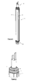
- FIG. 1 is a perspective view of a known piezoelectric actuator arrangement including a preferred embodiment of the present invention
- FIG. 2 is an enlarged detail perspective view of a first end of the actuator arrangement of FIG. 1 ,
- FIG. 3 is an enlarged sectional view of the first end of the actuator arrangement of FIG. 1 ,
- FIG. 4 is an enlarged sectional detail view of part of the second end of the actuator of FIG. 1 ,
- FIG. 5 is an enlarged view of part of the ball joint of the second end of the actuator of FIG. 1 ,
- FIG. 6 is an enlarged view of the markings on the ball joint of Fig. 5 .
- FIG. 7 is an enlarged cross section detail view of the markings on the ball joint of Fig. 6 .
- FIG. 1 shows all actuator arrangement, which is elongate and generally cylindrical in shape.
- the arrangement includes a known piezoelectric actuator 20 having at least one piezoelectric element (not shown), and is suitable for use in a fuel injector of an internal combustion engine.
- the actuator 20 includes a generally cylindrical body section 12, comprising: a central major portion 13 containing a piezoelectric stack; and first and second end pieces 14 and 16 respectively.
- End piece 14 at the first end of body section 12, includes an electrical connector with first and second terminals, which in use receives a voltage from a voltage supply (not shown).
- End piece 16 at the second end of body section 12, includes a load transmitting member which in use co-operates with a control piston or valve needle (not shown) of the fuel injector.
- end piece 14 is narrower than the major portion 13 such that in longitudinal cross-section the first end of body section 12 has a stepped profile comprising neck 125 and shoulder 126.
- end piece 16 is narrower than the major portion 13, apart from the similarly narrow neck 125 at the first end, such that in longitudinal cross-section the second end of body section 12 has a stepped profile comprising neck 127 and shoulder 128.
- each clip 30, 40 defines a ring in the form of a short expandable tube.
- clip 30 encircles body section 12 at neck 125, outwardly of shoulder 126. Additionally, it will be appreciated that clip 40 encircles body location of clips 30 and 40 can be seen in more detail in the sectional views of FIGS. 3 and 4 .
- FIGS. 3 and 4 Evident from FIGS. 3 and 4 is the presence of a flexible sleeve 50, which enshrouds and is conformed to the contours of body section 12.
- Sleeve 50 extends along the length of body section 12 from end piece 14 to end piece 16.
- clip 30 is positioned externally with respect to sleeve 50 around neck 125 of body section 12, such that the interior surface of clip 30 bears against the exterior of sleeve 50.
- Clip 30 is formed from a conventional spring wire material that can be expanded and contracted resiliently to vary its internal diameter. When positioned around neck 125, clip 30 exerts a constrictive force upon sleeve 50 sufficient to urge the interior of sleeve 50 against the exterior of body section 12. The constrictive force is sufficiently strong that a fluid-tight seal is maintained at the interface between sleeve 50 and body section 12 beneath clip 30.
- clip 40 is positioned externally with respect to sleeve 50 around neck 127, and forms a seal in the same way as described for clip 30.
- Clips 30 and 40 encircle necks 125, 127 respectively by at least two full turns of their coils around the circumference of those regions.
- the coiled shape provides a large, substantially continuous area of contact pressure against sleeve 50 beneath clips 30, 40, while minimising the external diameter of actuator arrangement 10.
- annular clip may be used to encircle body section 12 at neck 125, outwardly of shoulder 126, 127. It is to be appreciated that a similar annular clip could be provided at the second end of body section 12 to encircle body section 12 at neck 127, outwardly of shoulder 128. Such annular clips encircle necks 125, 127 by one full turn around the circumference of those regions.
- the annular clips are positioned externally with respect to sleeve 50 around necks 125, 127 respectively of body section 12 such that the interior female surface of each clip 60 bears against the exterior of sleeve 50.
- clips exert a constrictive force upon sleeve 50 sufficient to urge the interior of sleeve 50 against the exterior of body section 12.
- FIG. 5 a preferred embodiment of the end piece 16 is shown in more detail.
- Five horizontal, i.e. perpendicular to the axis of the actuator, circumferential, annular rough sections 130 alternating with four circumferential smooth sections 132 can be seen on the neck 127 of the second end piece 16.
- Each of the rough sections 130 comprises a series of zigzag lines 134 shown in more detail on FIG. 6 . These lines have been made by a laser marker.
- the cross section of a zigzag line is shown in more detail on FIG. 7 .
- the lines are in fact shallow grooves 136 flanked on each side by a lip 138, 140.
- the end piece 16 in this particular case has a total height of about 10 mm and a diameter of between 7,0 and 9.5 mm.
- the zone on the neck 127 of the end piece i.e. the underlying body section which comprises an alternation of smooth sections and rough sections, said rough sections comprising superficial markings is about 3,1 mm wide and in the present example comprises 8 rough sections and 7 smooth i.e. non marked zones in alternation with the rough sections.
- the superficial markings in the form of zigzag lines have been made a laser marking apparatus "Trumpf TruMark 6230" and have a depth "peak to valley" i.e.
- each rough section has a width of 210 ⁇ m and comprises 4 zigzag lines, the distance between to adjacent peaks is 100 ⁇ m, the length of the straight sections is 60 ⁇ m, the zigzag has an amplitude of 30 ⁇ m. The shortest distance between two adjacent lines is 30 ⁇ m.
- the constrictive force or the clamping load is sufficiently strong that a fluid-tight seal is maintained at the interfaces between sleeve 50 and body section 12 beneath the annular clips.
- the constrictive force exerted onto the sleeve was 50% higher than in an identical actuator without the alternation of smooth sections and rough sections, comprising superficial markings.
Landscapes
- Engineering & Computer Science (AREA)
- Chemical & Material Sciences (AREA)
- Combustion & Propulsion (AREA)
- Mechanical Engineering (AREA)
- General Engineering & Computer Science (AREA)
- Manufacturing & Machinery (AREA)
- Fuel-Injection Apparatus (AREA)
Abstract
Description
- The present invention relates to an actuator arrangement for use in a fuel injector of the type intended for use in a fuel system of an internal combustion engine. The invention relates, more particularly, to an end-seal of an actuator arrangement of a fuel injector of the accumulator or common rail type, the fuel injector being of the type controlled using a piezoelectric actuator.
- It is known to use piezoelectric actuators in fuel injectors of internal combustion engines. Such piezoelectrically operable fuel injectors provide a high degree of control over the timing of injection events within the combustion cycle and the volume of fuel that is delivered during each injection event. This permits improved control over the combustion process, which is essential in order to keep pace with increasingly stringent worldwide environmental regulations. Such fuel injectors may be employed in compression ignition (diesel) engines or spark ignition (petrol) engines.
- A typical piezoelectric actuator unit designed for use in an automotive fuel injector has a stack structure formed from an alternating sequence of piezoelectric elements or layers and planar internal electrodes. The piezoelectric layers, in turn, form an alternating sequence of oppositely polarised layers, and the internal electrodes form an alternating sequence of positive and negative internal electrodes. The positive internal electrodes are in electrical connection with a first external electrode, hereinafter referred to as the positive side electrode. Likewise, the internal electrodes of the negative group are in electrical connection with a second external electrode, hereinafter referred to as the negative side electrode.
- If a voltage is applied between the two external electrodes, the resulting electric fields between each adjacent pair of positive and negative internal electrodes cause each piezoelectric layer, and therefore the piezoelectric stack, to undergo a strain along its length, i.e. along an axis normal to the plane of each internal electrode. Because of the polarisation of the piezoelectric layers, it follows that not only can the magnitude of the strain be controlled by adjusting the applied voltage, but also the direction of the strain can be reversed by switching the polarity of the applied voltage. Rapidly varying the magnitude and/or polarity of the applied voltage causes rapid changes in the strength and/or direction of the electric fields across the piezoelectric layers, and consequentially rapid variations in the length of the piezoelectric actuator. Typically, the piezoelectric layers of the stack are formed from a ferroelectric material such as lead zirconate titanate (PZT).
- Such an actuator is suitable for use in a fuel injector, for example of the type known from the present Applicant's European Patent No.
EP 0995901 . The fuel injector is arranged so that a change in length of the actuator results in a movement of a valve needle. The needle can be thus raised from or lowered onto a valve seat by control of the actuator length so as to permit a quantity of fuel to pass through drillings provided in the valve seat. - In use, the actuator of such a fuel injector is surrounded by fuel at high pressure. The fuel pressure may be up to or above 2000 bar. In order to protect the piezoelectric actuator from damage and potential failure, the piezoelectric actuator must be isolated from this environment by at least a layer of barrier material, herein referred to as 'encapsulation member'. It is known to encapsulate the piezoelectric actuator with an inert fluoropolymer, for example as described in the Applicant's PCT published Patent Application No.
WO02/061856A1 EP 1356529 A ), which acts to prevent permeation of liquid fuel, water and contaminant substances dissolved in the water or fuel, into the structure of the actuator. The encapsulation means must also be able to withstand fuel and water permeation over the entire operational temperature range of between around -40°C to around 175°C during the lifetime of the fuel injector which is about 10 years. - A piezoelectric actuator suitable for use in an automotive fuel injector, comprising a device body bearing encapsulation member to protectively encapsulate the device body wherein the encapsulation member includes several organic layers and at least one metal layer is known from the Applicant's published
PCT Patent Application No. WO2007093921 A - It has been observed, however, that there may still be ingress of fluid into the interface between the actuator and the coating or sleeve. For example, the aforementioned sleeves are preferably formed from elastic or heat-shrink materials such as tubes with open first and second ends such that the actuator can be inserted into the open tube. The tube is then allowed to contract elastically, or is made to contract by the application of heat (i.e. heat shrinkage), in order to encapsulate the actuator. It will be understood that although the sleeve now bears tightly against the actuator, the first and second ends of the tube present paths for the ingress of fluid into the interface between the coating and the encapsulated actuator.
- One or more clips may be provided at the ends of the sleeve in order to improve end sealing, as described in the Applicant's co-pending application
EP 05256852 - Nevertheless, under the challenging environmental conditions within a fuel injector there remains a risk that fluid may migrate underneath the ends of the sleeve despite the presence of the clips.
- It is known to provide a filler material, as described, for example, in the Applicant's co-pending application
WO 02/061856 - It has been found that in the known encapsulations, the seal of the organic polymer sleeve at both ends of the actuator provides a weak spot allowing over time the infiltrations of liquids such as diesel fuel, rapeseed methyl ester (RME) based fuels and water in the actuator and that further efforts are needed to ensure a better encapsulation at reasonable costs. It is indeed often a matter of time and temperature, as to when fuel or other liquids will permeate through the end seals of the encapsulation means leading to fatal component failure of the piezoelectric actuator and, thus, the fuel injector as a whole. Different solutions to this problem have already been proposed.
- In the Applicant's co-pending application
EP 1783842 A1 , there is provided an actuator arrangement comprising a piezoelectric actuator having a body section, a shroud which enshrouds at least part of the body section of the actuator, and at least one constrictive member disposed externally with respect to the shroud. The constrictive member applies a constrictive force to the shroud to maintain a seal between the shroud and the underlying body section of the actuator. - In the Applicant's co-pending application
W02007/128948 , there is provided a method for enshrouding an actuator for use in a fuel injector, comprising the steps of providing an actuator, having a body section, a first end piece and a second end piece; providing a shroud having first and second ends; applying a sealant material to at least one portion of an exterior surface of the end pieces, and/or to at least one part of the shroud; and enshrouding the actuator with the shroud, such that the sealant material provides an intermediate layer between the end pieces and the shroud and forms a fluid-tight seal between them. - Against this background, it would be desirable to provide an improved encapsulating means, which provides a reduced permeability at the end pieces to fuel, water and other substances therein over time.
- This object is achieved by an actuator arrangement for use in a fuel injector, comprising: a piezoelectric actuator having a body section, said body section having a first end piece and a second end piece; a sleeve which enshrouds at least part of the body section of the actuator; and at least one constrictive member, disposed externally with respect to the sleeve wherein the constrictive member applies a constrictive force to the sleeve to maintain a seal between the sleeve and the underlying body section of the actuator characterized in that the underlying body section comprises an alternation of smooth sections and rough sections, said rough sections comprising superficial markings or engravings. It is understood that these markings nevertheless have a certain depth.
- It is understood that the term rough has to be seen in relative to the term smooth, the smooth surface being the non-treated surface whereas the rough surface being the treated surface.
- The smooth and rough sections are preferably perpendicular to the longitudinal axis of the actuator arrangement respectively the piezoelectric stack. The smooth and rough sections are preferably annular sections, i.e. are situated around the entire perimeter of the underlying bodysection.
- The markings comprise preferably straight lines, wavy lines, zigzag lines, dots or combinations thereof. The best results are obtained with a ratio between the rough sections and the smooth sections comprised between about 20-80 and about 80-20, preferably between about 40-60 and about 60-40 and most preferably at about 50-50.
- The number of rough sections is preferably comprised between 3 and 10 and the number of smooth sections is preferably comprised between 3 and 10.
- The width of the sections is preferably comprised between 0.1 and 0.5 mm and more preferably between 0.2 and 0.4 mm.
- The depth of the superficial markings is comprised preferably between 10 µm and 40 µm from peak to valley.
- The underlying bodysection, i.e. the end piece is made of plastic preferably of a fluoropolymeric material and most preferably of ethylene tetrafluoroethylene (ETFE).
- The major advantage of the actuator arrangement according to the invention is to provide a piezoelectric actuator stack, which has an improved fuel seal over time at at least one of the end pieces.
- It has been found during the research leading to the present invention that the constrictive force i.e. the clamping load of the constriction means at the end piece side, in particular the ball joint side, leads to an excessive flowing of the polymer of which this end piece is made, when exposed to hot temperature conditions between 110 and 130°C. The flowing of the polymer at high temperatures may lead to a partial or even sometimes complete loss of the clamping load, which may lead in turn to a lack of sealing under certain temperature end pressure conditions.
- Surprisingly, it has been found that superficial markings by a so called marking laser or by electro discharge machining (EDM) at some locations of the end piece also called ball joint allow to significantly enhance the clamping load on the end piece after the production. It has also been found that the clamping load remains high even under severe temperature and pressure conditions. It is thus possible obtain a better seal between the sleeve and the end piece, not only at low temperatures but also at high temperatures and over time.
- Laser systems suitable for marking and engraving the rough sections are widely available and are commonly used to apply computer-generated images (bar codes, labeling equipment, serial numbers, logos, UID, etc.) to a wide variety of metallic and nonmetallic materials. A variety of manufacturers offer suitable apparatuses for the purpose.
- Electric discharge machining (EDM), sometimes colloquially also referred to as spark machining, spark eroding, burning, die sinking or wire erosion, is a manufacturing process whereby material is removed from the workpiece by a series of rapidly recurring current discharges between two electrodes, separated by a dielectric liquid and subject to an electric voltage. One of the electrodes is called the tool-electrode, or simply the 'tool' or 'electrode', while the other is called the workpiece-electrode, or 'workpiece'. As an alternative to the above discussed laser systems, EDM may be used to create the rough sections. A variety of manufacturers offer suitable EDM equipment for the purpose.
- The actuator arrangement may, according to a preferred embodiment, further comprise a metallic film positioned around the sleeve.
- Such a metallic film may be realized in different ways known to those skilled in the art. Some suitable examples are described in more detail in
W02007/093921 . Aluminum and stainless steel are preferred for the metallic film. - The material of the sleeve may be chemically or physically modified in order to bond to the substrate or surface of the stack, to facilitate bonding to the stack or to the optional metallic film.
- A large number of polymers are currently available to produce the sleeve:
- PTFE (fluoropolymer) tubes have the widest operating temperature range (-270 to 260 °C), low coefficient of friction, and high resistance to chemicals. 1.5:1, 2:1 and 4:1 shrink ratios are available on the market.
- Viton, another fluoropolymer with high chemical resistance and highly flexible. Viton is a brand of synthetic rubber and fluoropolymer elastomer commonly used in moulded or extruded goods. The name is a registered trademark of DuPont Performance Elastomers L.L.C.. Viton fluoroelastomers are categorized under the ASTM D1418 & ISO 1629 designation of FKM. This class of elastomers is a family comprising copolymers of hexafluoropropylene (HFP) and vinylidene fluoride (VDF or VF2), terpolymers of tetrafluoroethylene (TFE), vinylidene fluoride (VDF) and hexafluoropropylene (HFP) as well as perfluoromethylvinylether (PMVE) containing specialties.
- Polyvinylidene fluoride (PVDF) tubes are intended for high temperature applications; -55 °C up to 150 °C (flexible PVDF) or up to 175 °C (semi-rigid Kynar). Common shrink ratio is 2:1, and shrink temperature ranges around 170°C.
- Fluorinated ethylene propylene (FEP) is a lower-cost alternative to PTFE. Its operating temperature range is up to 204 °C and the shrink temperature is as low as 190 °C. Available shrink ratios are 3:1 and 6:1.
- Silicone rubber offers excellent resistance to scrape abrasion and high flexibility. The shrink temperature is 200 °C
- Particularly preferred in the context of the present invention are the following thermoplastic polymers for heat shrinkable sleeves: ethylene tetrafluoroethylene (ETFE), a polytetrafluoroethylene (PTFE) thermoplastic, a polyvinyldifluoride (PVDF), a fluorinated ethylene-propylene (FEP), a perfluoroalkoxy (PFA) or a polytetrafluoroethylene-perfluoromethylvinylether (MFA) and polymers of tetrafluoroethylene, hexafluoropropylene and vinylidene fluoride (THV).
- Embodiments of the present invention will now be described, by way of example only, with reference to the accompanying drawings, in which:
-
FIG. 1 is a perspective view of a known piezoelectric actuator arrangement including a preferred embodiment of the present invention; -
FIG. 2 is an enlarged detail perspective view of a first end of the actuator arrangement ofFIG. 1 , -
FIG. 3 is an enlarged sectional view of the first end of the actuator arrangement ofFIG. 1 , -
FIG. 4 is an enlarged sectional detail view of part of the second end of the actuator ofFIG. 1 , -
FIG. 5 is an enlarged view of part of the ball joint of the second end of the actuator ofFIG. 1 , -
FIG. 6 is an enlarged view of the markings on the ball joint ofFig. 5 , -
FIG. 7 is an enlarged cross section detail view of the markings on the ball joint ofFig. 6 , -
FIG. 1 shows all actuator arrangement, which is elongate and generally cylindrical in shape. The arrangement includes a knownpiezoelectric actuator 20 having at least one piezoelectric element (not shown), and is suitable for use in a fuel injector of an internal combustion engine. - The
actuator 20 includes a generallycylindrical body section 12, comprising: a centralmajor portion 13 containing a piezoelectric stack; and first andsecond end pieces End piece 14, at the first end ofbody section 12, includes an electrical connector with first and second terminals, which in use receives a voltage from a voltage supply (not shown).End piece 16, at the second end ofbody section 12, includes a load transmitting member which in use co-operates with a control piston or valve needle (not shown) of the fuel injector. - As shown in
FIG. 2 , inwardly of the electrical connector at the first end ofbody section 12,end piece 14 is narrower than themajor portion 13 such that in longitudinal cross-section the first end ofbody section 12 has a steppedprofile comprising neck 125 andshoulder 126. Although not shown isFIG. 2 , it will be appreciated that inwardly of the load transmitting member at the second end ofbody section 12,end piece 16 is narrower than themajor portion 13, apart from the similarlynarrow neck 125 at the first end, such that in longitudinal cross-section the second end ofbody section 12 has a steppedprofile comprising neck 127 andshoulder 128. - Details of the piezoelectric stack and internal components of
actuator 20 and a description of how the actuator operates are disclosed fully in the Applicant's granted patentEP 0995901 , so will not be discussed here. - Referring to
FIGS. 2 to 4 , there are providedcoiled clips body section 12. The successive coils ofclips clip - As shown in detail in
FIG. 2 ,clip 30 encirclesbody section 12 atneck 125, outwardly ofshoulder 126. Additionally, it will be appreciated thatclip 40 encircles body location ofclips FIGS. 3 and 4 . - Evident from
FIGS. 3 and 4 is the presence of aflexible sleeve 50, which enshrouds and is conformed to the contours ofbody section 12.Sleeve 50 extends along the length ofbody section 12 fromend piece 14 to endpiece 16. - Referring to
FIG. 3 ,clip 30 is positioned externally with respect tosleeve 50 aroundneck 125 ofbody section 12, such that the interior surface ofclip 30 bears against the exterior ofsleeve 50.Clip 30 is formed from a conventional spring wire material that can be expanded and contracted resiliently to vary its internal diameter. When positioned aroundneck 125,clip 30 exerts a constrictive force uponsleeve 50 sufficient to urge the interior ofsleeve 50 against the exterior ofbody section 12. The constrictive force is sufficiently strong that a fluid-tight seal is maintained at the interface betweensleeve 50 andbody section 12 beneathclip 30. - From
FIG. 4 it can be seen thatclip 40 is positioned externally with respect tosleeve 50 aroundneck 127, and forms a seal in the same way as described forclip 30. -
Clips encircle necks sleeve 50 beneathclips - Alternatively to the clips described above, an annular clip may be used to encircle
body section 12 atneck 125, outwardly ofshoulder body section 12 to encirclebody section 12 atneck 127, outwardly ofshoulder 128. Such annular clips encirclenecks - The annular clips are positioned externally with respect to
sleeve 50 aroundnecks body section 12 such that the interior female surface of each clip 60 bears against the exterior ofsleeve 50. When positioned aroundnecks sleeve 50 sufficient to urge the interior ofsleeve 50 against the exterior ofbody section 12. These coiled clips and annular clips are described in detail in Applicant's granted European patentEP 1783842 and are therefore not described in detail herein. - Referring now to
FIG. 5 , a preferred embodiment of theend piece 16 is shown in more detail. Five horizontal, i.e. perpendicular to the axis of the actuator, circumferential, annularrough sections 130 alternating with four circumferentialsmooth sections 132 can be seen on theneck 127 of thesecond end piece 16. Each of therough sections 130 comprises a series ofzigzag lines 134 shown in more detail onFIG. 6 . These lines have been made by a laser marker. The cross section of a zigzag line is shown in more detail onFIG. 7 . The lines are in factshallow grooves 136 flanked on each side by alip - The
end piece 16 in this particular case has a total height of about 10 mm and a diameter of between 7,0 and 9.5 mm. The zone on theneck 127 of the end piece i.e. the underlying body section which comprises an alternation of smooth sections and rough sections, said rough sections comprising superficial markings is about 3,1 mm wide and in the present example comprises 8 rough sections and 7 smooth i.e. non marked zones in alternation with the rough sections. The superficial markings in the form of zigzag lines have been made a laser marking apparatus "Trumpf TruMark 6230" and have a depth "peak to valley" i.e. from the top of the lip to the bottom of the groove of 15 µm and a width of 40µm, measured between the top of the lips..Each rough section has a width of 210µm and comprises 4 zigzag lines, the distance between to adjacent peaks is 100 µm, the length of the straight sections is 60µm, the zigzag has an amplitude of 30 µm. The shortest distance between two adjacent lines is 30µm. - The constrictive force or the clamping load is sufficiently strong that a fluid-tight seal is maintained at the interfaces between
sleeve 50 andbody section 12 beneath the annular clips. - Surprisingly, the constrictive force exerted onto the sleeve was 50% higher than in an identical actuator without the alternation of smooth sections and rough sections, comprising superficial markings.
-
- 12
- body section
- 13
- central major portion
- 14
- first end piece
- 16
- second end piece
- 20
- piezoelectric actuator
- 30
- clips
- 40
- clips
- 50
- sleeve
- 125
- neck of first end piece
- 126
- shoulder of first end piece
- 127
- neck of second end piece
- 128
- shoulder of second end piece
- 130
- rough section
- 132
- smooth section
- 134
- zigzag line
- 136
- groove
- 138
- lip
- 140
- lip
Claims (12)
- An actuator arrangement for use in a fuel injector, comprising: a piezoelectric actuator having a body section, said body section having a first end piece and a second end piece; a sleeve which enshrouds at least part of the body section of the actuator; and at least one constrictive member, disposed externally with respect to the sleeve wherein the constrictive member applies a constrictive force to the sleeve to maintain a seal between the sleeve and the underlying body section of the actuator characterized in that the underlying body section comprises an alternation of smooth sections and rough sections, said rough sections comprising superficial markings.
- The actuator arrangement according to claim 1, wherein the smooth sections and the rough sections are perpendicular to a longitudinal axis of the actuator arrangement.
- The actuator arrangement according to claims 1 or 2, wherein the smooth sections and the rough sections are annular sections.
- The actuator arrangement according any of the claims 1 to 3, wherein the underlying body section is at least one end piece.
- The actuator arrangement according any of the claims 1 to 4, wherein the markings comprise straight lines, wavy lines, zigzag lines, dots or combinations thereof.
- The actuator arrangement according any of the claims 1 to 5, wherein the ratio between the rough sections and the smooth sections is comprised between 20-80 and 80-20.
- The actuator arrangement according to any of the claims 1 to 6, wherein he number of rough sections is comprised between 3 and 10.
- The actuator arrangement according to any of the claims 1 to 7, wherein the number of smooth sections is comprised between 3 and 10.
- The actuator arrangement according to any of the claims 1 to 8, wherein the width of the sections is comprised between 0.1 and 0.5 mm.
- The actuator arrangement according to any of the claims 1 to 9, wherein the superficial markings have a depth measured from peak to valley comprised between 10 µm and 40 µm.
- The actuator arrangement according to any of the claims 1 to 10, wherein the end piece is made of plastic preferably of a fluoropolymeric material and most preferably of ethylene tetrafluoroethylene (ETFE).
- The actuator arrangement according to any of the claims 1 to 11, wherein the actuator arrangement further comprises a metallic film positioned around the sleeve.
Priority Applications (1)
| Application Number | Priority Date | Filing Date | Title |
|---|---|---|---|
| EP20100157760 EP2372139B1 (en) | 2010-03-25 | 2010-03-25 | Actuator Arrangement for use in a Fuel Injector |
Applications Claiming Priority (1)
| Application Number | Priority Date | Filing Date | Title |
|---|---|---|---|
| EP20100157760 EP2372139B1 (en) | 2010-03-25 | 2010-03-25 | Actuator Arrangement for use in a Fuel Injector |
Publications (2)
| Publication Number | Publication Date |
|---|---|
| EP2372139A1 true EP2372139A1 (en) | 2011-10-05 |
| EP2372139B1 EP2372139B1 (en) | 2012-10-31 |
Family
ID=42371491
Family Applications (1)
| Application Number | Title | Priority Date | Filing Date |
|---|---|---|---|
| EP20100157760 Active EP2372139B1 (en) | 2010-03-25 | 2010-03-25 | Actuator Arrangement for use in a Fuel Injector |
Country Status (1)
| Country | Link |
|---|---|
| EP (1) | EP2372139B1 (en) |
Cited By (1)
| Publication number | Priority date | Publication date | Assignee | Title |
|---|---|---|---|---|
| CN104812682A (en) * | 2012-11-09 | 2015-07-29 | 世伟洛克公司 | Actuator with visual indicator sleeve |
Citations (8)
| Publication number | Priority date | Publication date | Assignee | Title |
|---|---|---|---|---|
| EP0995901A1 (en) | 1998-10-22 | 2000-04-26 | Lucas Industries Limited | Fuel injector |
| WO2002061856A1 (en) | 2001-02-01 | 2002-08-08 | Delphi Technologies, Inc. | Method of assembling an actuator arrangement |
| US20070057095A1 (en) * | 2005-08-26 | 2007-03-15 | Johann Bayer | Metallic compression joint and fuel injector having a metallic compression joint |
| EP1783842A1 (en) | 2005-11-04 | 2007-05-09 | Delphi Technologies, Inc. | Actuator arrangement |
| WO2007093921A2 (en) | 2006-02-14 | 2007-08-23 | Delphi Technologies, Inc. | Barrier coatings for a piezoelectric device |
| WO2007128948A1 (en) | 2006-05-03 | 2007-11-15 | Delphi Technologies, Inc. | Method for enshrouding an actuator |
| EP1901360A2 (en) * | 2006-09-14 | 2008-03-19 | Robert Bosch Gmbh | Piezo actuator module with a cladded piezo actuator |
| EP2014966A2 (en) * | 2007-06-15 | 2009-01-14 | Delphi Technologies, Inc. | A bellows like collapsible clip |
-
2010
- 2010-03-25 EP EP20100157760 patent/EP2372139B1/en active Active
Patent Citations (9)
| Publication number | Priority date | Publication date | Assignee | Title |
|---|---|---|---|---|
| EP0995901A1 (en) | 1998-10-22 | 2000-04-26 | Lucas Industries Limited | Fuel injector |
| WO2002061856A1 (en) | 2001-02-01 | 2002-08-08 | Delphi Technologies, Inc. | Method of assembling an actuator arrangement |
| EP1356529A1 (en) | 2001-02-01 | 2003-10-29 | Delphi Technologies, Inc. | Method of assembling an actuator arrangement |
| US20070057095A1 (en) * | 2005-08-26 | 2007-03-15 | Johann Bayer | Metallic compression joint and fuel injector having a metallic compression joint |
| EP1783842A1 (en) | 2005-11-04 | 2007-05-09 | Delphi Technologies, Inc. | Actuator arrangement |
| WO2007093921A2 (en) | 2006-02-14 | 2007-08-23 | Delphi Technologies, Inc. | Barrier coatings for a piezoelectric device |
| WO2007128948A1 (en) | 2006-05-03 | 2007-11-15 | Delphi Technologies, Inc. | Method for enshrouding an actuator |
| EP1901360A2 (en) * | 2006-09-14 | 2008-03-19 | Robert Bosch Gmbh | Piezo actuator module with a cladded piezo actuator |
| EP2014966A2 (en) * | 2007-06-15 | 2009-01-14 | Delphi Technologies, Inc. | A bellows like collapsible clip |
Cited By (1)
| Publication number | Priority date | Publication date | Assignee | Title |
|---|---|---|---|---|
| CN104812682A (en) * | 2012-11-09 | 2015-07-29 | 世伟洛克公司 | Actuator with visual indicator sleeve |
Also Published As
| Publication number | Publication date |
|---|---|
| EP2372139B1 (en) | 2012-10-31 |
Similar Documents
| Publication | Publication Date | Title |
|---|---|---|
| EP1356529B1 (en) | Method of assembling an actuator arrangement | |
| US7595579B2 (en) | Piezoelectric actuator module with a sheathed piezoelectric actuator | |
| KR101682070B1 (en) | Sealing structure | |
| EP1783842B1 (en) | Actuator arrangement | |
| EP1906464A1 (en) | Piezo actuator with a jacket for placing in a piezo injector | |
| EP2013921B1 (en) | Method for enshrouding an actuator | |
| EP2372139B1 (en) | Actuator Arrangement for use in a Fuel Injector | |
| JP2009527117A (en) | Piezoelectric actuator | |
| EP2343746B1 (en) | Method of Encapsulating an Actuator having a Piezoelectric Actuator Stack | |
| US20050199745A1 (en) | Method of assembling a fuel injector | |
| JP4898838B2 (en) | Piezoelectric actuator | |
| US9683663B2 (en) | Electroactive actuators, systems equipped therewith, and methods of use and manufacture | |
| EP2426749A1 (en) | Actuator arrangement for use in a fuel injector | |
| JP4221481B2 (en) | Piezoelectric actuator | |
| EP2378107A1 (en) | Actuator arrangement for use in a fuel injector | |
| EP2014966B1 (en) | Methods of fitting a clip to secure a sleeve to the body of a piezo electric actuator | |
| JP4305294B2 (en) | Ignition device for internal combustion engine | |
| EP2224123A1 (en) | Piezoelectric actuator | |
| US20100258086A1 (en) | Piezoelectric Device | |
| WO2012095377A1 (en) | Actuator arrangement for use in a fuel injector | |
| EP1909339B1 (en) | Actuator module having an enshrouded piezo actuator | |
| EP1925915B1 (en) | Submersible device sealing system and method | |
| DE102012201900A1 (en) | exhaust gas sensor | |
| WO2012069235A1 (en) | Piezoelectric actuator module, and fuel injection valve | |
| JP7076310B2 (en) | Glow plugs and their manufacturing methods |
Legal Events
| Date | Code | Title | Description |
|---|---|---|---|
| PUAI | Public reference made under article 153(3) epc to a published international application that has entered the european phase |
Free format text: ORIGINAL CODE: 0009012 |
|
| AK | Designated contracting states |
Kind code of ref document: A1 Designated state(s): AT BE BG CH CY CZ DE DK EE ES FI FR GB GR HR HU IE IS IT LI LT LU LV MC MK MT NL NO PL PT RO SE SI SK SM TR |
|
| AX | Request for extension of the european patent |
Extension state: AL BA ME RS |
|
| 17P | Request for examination filed |
Effective date: 20120405 |
|
| GRAP | Despatch of communication of intention to grant a patent |
Free format text: ORIGINAL CODE: EPIDOSNIGR1 |
|
| GRAS | Grant fee paid |
Free format text: ORIGINAL CODE: EPIDOSNIGR3 |
|
| GRAA | (expected) grant |
Free format text: ORIGINAL CODE: 0009210 |
|
| AK | Designated contracting states |
Kind code of ref document: B1 Designated state(s): AT BE BG CH CY CZ DE DK EE ES FI FR GB GR HR HU IE IS IT LI LT LU LV MC MK MT NL NO PL PT RO SE SI SK SM TR |
|
| AX | Request for extension of the european patent |
Extension state: AL BA ME RS |
|
| REG | Reference to a national code |
Ref country code: GB Ref legal event code: FG4D Ref country code: CH Ref legal event code: EP |
|
| REG | Reference to a national code |
Ref country code: AT Ref legal event code: REF Ref document number: 582159 Country of ref document: AT Kind code of ref document: T Effective date: 20121115 |
|
| REG | Reference to a national code |
Ref country code: IE Ref legal event code: FG4D |
|
| REG | Reference to a national code |
Ref country code: DE Ref legal event code: R096 Ref document number: 602010003384 Country of ref document: DE Effective date: 20121227 |
|
| REG | Reference to a national code |
Ref country code: AT Ref legal event code: MK05 Ref document number: 582159 Country of ref document: AT Kind code of ref document: T Effective date: 20121031 |
|
| REG | Reference to a national code |
Ref country code: LT Ref legal event code: MG4D |
|
| REG | Reference to a national code |
Ref country code: NL Ref legal event code: VDEP Effective date: 20121031 |
|
| PG25 | Lapsed in a contracting state [announced via postgrant information from national office to epo] |
Ref country code: IS Free format text: LAPSE BECAUSE OF FAILURE TO SUBMIT A TRANSLATION OF THE DESCRIPTION OR TO PAY THE FEE WITHIN THE PRESCRIBED TIME-LIMIT Effective date: 20130228 Ref country code: FI Free format text: LAPSE BECAUSE OF FAILURE TO SUBMIT A TRANSLATION OF THE DESCRIPTION OR TO PAY THE FEE WITHIN THE PRESCRIBED TIME-LIMIT Effective date: 20121031 Ref country code: LT Free format text: LAPSE BECAUSE OF FAILURE TO SUBMIT A TRANSLATION OF THE DESCRIPTION OR TO PAY THE FEE WITHIN THE PRESCRIBED TIME-LIMIT Effective date: 20121031 Ref country code: HR Free format text: LAPSE BECAUSE OF FAILURE TO SUBMIT A TRANSLATION OF THE DESCRIPTION OR TO PAY THE FEE WITHIN THE PRESCRIBED TIME-LIMIT Effective date: 20121031 Ref country code: NL Free format text: LAPSE BECAUSE OF FAILURE TO SUBMIT A TRANSLATION OF THE DESCRIPTION OR TO PAY THE FEE WITHIN THE PRESCRIBED TIME-LIMIT Effective date: 20121031 Ref country code: SE Free format text: LAPSE BECAUSE OF FAILURE TO SUBMIT A TRANSLATION OF THE DESCRIPTION OR TO PAY THE FEE WITHIN THE PRESCRIBED TIME-LIMIT Effective date: 20121031 Ref country code: NO Free format text: LAPSE BECAUSE OF FAILURE TO SUBMIT A TRANSLATION OF THE DESCRIPTION OR TO PAY THE FEE WITHIN THE PRESCRIBED TIME-LIMIT Effective date: 20130131 |
|
| PG25 | Lapsed in a contracting state [announced via postgrant information from national office to epo] |
Ref country code: LV Free format text: LAPSE BECAUSE OF FAILURE TO SUBMIT A TRANSLATION OF THE DESCRIPTION OR TO PAY THE FEE WITHIN THE PRESCRIBED TIME-LIMIT Effective date: 20121031 Ref country code: BE Free format text: LAPSE BECAUSE OF FAILURE TO SUBMIT A TRANSLATION OF THE DESCRIPTION OR TO PAY THE FEE WITHIN THE PRESCRIBED TIME-LIMIT Effective date: 20121031 Ref country code: GR Free format text: LAPSE BECAUSE OF FAILURE TO SUBMIT A TRANSLATION OF THE DESCRIPTION OR TO PAY THE FEE WITHIN THE PRESCRIBED TIME-LIMIT Effective date: 20130201 Ref country code: PL Free format text: LAPSE BECAUSE OF FAILURE TO SUBMIT A TRANSLATION OF THE DESCRIPTION OR TO PAY THE FEE WITHIN THE PRESCRIBED TIME-LIMIT Effective date: 20121031 Ref country code: SI Free format text: LAPSE BECAUSE OF FAILURE TO SUBMIT A TRANSLATION OF THE DESCRIPTION OR TO PAY THE FEE WITHIN THE PRESCRIBED TIME-LIMIT Effective date: 20121031 Ref country code: PT Free format text: LAPSE BECAUSE OF FAILURE TO SUBMIT A TRANSLATION OF THE DESCRIPTION OR TO PAY THE FEE WITHIN THE PRESCRIBED TIME-LIMIT Effective date: 20130228 |
|
| PG25 | Lapsed in a contracting state [announced via postgrant information from national office to epo] |
Ref country code: AT Free format text: LAPSE BECAUSE OF FAILURE TO SUBMIT A TRANSLATION OF THE DESCRIPTION OR TO PAY THE FEE WITHIN THE PRESCRIBED TIME-LIMIT Effective date: 20121031 |
|
| PG25 | Lapsed in a contracting state [announced via postgrant information from national office to epo] |
Ref country code: BG Free format text: LAPSE BECAUSE OF FAILURE TO SUBMIT A TRANSLATION OF THE DESCRIPTION OR TO PAY THE FEE WITHIN THE PRESCRIBED TIME-LIMIT Effective date: 20130131 Ref country code: SK Free format text: LAPSE BECAUSE OF FAILURE TO SUBMIT A TRANSLATION OF THE DESCRIPTION OR TO PAY THE FEE WITHIN THE PRESCRIBED TIME-LIMIT Effective date: 20121031 Ref country code: CZ Free format text: LAPSE BECAUSE OF FAILURE TO SUBMIT A TRANSLATION OF THE DESCRIPTION OR TO PAY THE FEE WITHIN THE PRESCRIBED TIME-LIMIT Effective date: 20121031 Ref country code: DK Free format text: LAPSE BECAUSE OF FAILURE TO SUBMIT A TRANSLATION OF THE DESCRIPTION OR TO PAY THE FEE WITHIN THE PRESCRIBED TIME-LIMIT Effective date: 20121031 Ref country code: EE Free format text: LAPSE BECAUSE OF FAILURE TO SUBMIT A TRANSLATION OF THE DESCRIPTION OR TO PAY THE FEE WITHIN THE PRESCRIBED TIME-LIMIT Effective date: 20121031 |
|
| PG25 | Lapsed in a contracting state [announced via postgrant information from national office to epo] |
Ref country code: IT Free format text: LAPSE BECAUSE OF FAILURE TO SUBMIT A TRANSLATION OF THE DESCRIPTION OR TO PAY THE FEE WITHIN THE PRESCRIBED TIME-LIMIT Effective date: 20121031 Ref country code: RO Free format text: LAPSE BECAUSE OF FAILURE TO SUBMIT A TRANSLATION OF THE DESCRIPTION OR TO PAY THE FEE WITHIN THE PRESCRIBED TIME-LIMIT Effective date: 20121031 |
|
| PLBE | No opposition filed within time limit |
Free format text: ORIGINAL CODE: 0009261 |
|
| STAA | Information on the status of an ep patent application or granted ep patent |
Free format text: STATUS: NO OPPOSITION FILED WITHIN TIME LIMIT |
|
| REG | Reference to a national code |
Ref country code: HU Ref legal event code: AG4A Ref document number: E016518 Country of ref document: HU |
|
| 26N | No opposition filed |
Effective date: 20130801 |
|
| PG25 | Lapsed in a contracting state [announced via postgrant information from national office to epo] |
Ref country code: MC Free format text: LAPSE BECAUSE OF NON-PAYMENT OF DUE FEES Effective date: 20130331 Ref country code: ES Free format text: LAPSE BECAUSE OF FAILURE TO SUBMIT A TRANSLATION OF THE DESCRIPTION OR TO PAY THE FEE WITHIN THE PRESCRIBED TIME-LIMIT Effective date: 20130211 |
|
| REG | Reference to a national code |
Ref country code: DE Ref legal event code: R097 Ref document number: 602010003384 Country of ref document: DE Effective date: 20130801 |
|
| PG25 | Lapsed in a contracting state [announced via postgrant information from national office to epo] |
Ref country code: CY Free format text: LAPSE BECAUSE OF FAILURE TO SUBMIT A TRANSLATION OF THE DESCRIPTION OR TO PAY THE FEE WITHIN THE PRESCRIBED TIME-LIMIT Effective date: 20121031 |
|
| REG | Reference to a national code |
Ref country code: IE Ref legal event code: MM4A |
|
| PG25 | Lapsed in a contracting state [announced via postgrant information from national office to epo] |
Ref country code: IE Free format text: LAPSE BECAUSE OF NON-PAYMENT OF DUE FEES Effective date: 20130325 |
|
| REG | Reference to a national code |
Ref country code: FR Ref legal event code: TP Owner name: DELPHI INTERNATIONAL OPERATIONS LUXEMBOURG S.A, LU Effective date: 20140516 |
|
| REG | Reference to a national code |
Ref country code: HU Ref legal event code: GB9C Owner name: DELPHI INTERNATIONAL OPERATIONS LUXEMBOURG S.A, LU Free format text: FORMER OWNER(S): DELPHI TECHNOLOGIES HOLDING S.A.R.L., LU |
|
| PG25 | Lapsed in a contracting state [announced via postgrant information from national office to epo] |
Ref country code: MT Free format text: LAPSE BECAUSE OF FAILURE TO SUBMIT A TRANSLATION OF THE DESCRIPTION OR TO PAY THE FEE WITHIN THE PRESCRIBED TIME-LIMIT Effective date: 20121031 |
|
| REG | Reference to a national code |
Ref country code: DE Ref legal event code: R081 Ref document number: 602010003384 Country of ref document: DE Owner name: DELPHI INTERNATIONAL OPERATIONS LUXEMBOURG S.A, LU Free format text: FORMER OWNER: DELPHI TECHNOLOGIES HOLDING S.A.R.L., BASCHARAGE, LU Effective date: 20140715 |
|
| REG | Reference to a national code |
Ref country code: CH Ref legal event code: PL |
|
| GBPC | Gb: european patent ceased through non-payment of renewal fee |
Effective date: 20140325 |
|
| PG25 | Lapsed in a contracting state [announced via postgrant information from national office to epo] |
Ref country code: LI Free format text: LAPSE BECAUSE OF NON-PAYMENT OF DUE FEES Effective date: 20140331 Ref country code: GB Free format text: LAPSE BECAUSE OF NON-PAYMENT OF DUE FEES Effective date: 20140325 Ref country code: CH Free format text: LAPSE BECAUSE OF NON-PAYMENT OF DUE FEES Effective date: 20140331 |
|
| REG | Reference to a national code |
Ref country code: FR Ref legal event code: PLFP Year of fee payment: 6 |
|
| PGFP | Annual fee paid to national office [announced via postgrant information from national office to epo] |
Ref country code: HU Payment date: 20150310 Year of fee payment: 6 Ref country code: DE Payment date: 20150327 Year of fee payment: 6 |
|
| PG25 | Lapsed in a contracting state [announced via postgrant information from national office to epo] |
Ref country code: SM Free format text: LAPSE BECAUSE OF FAILURE TO SUBMIT A TRANSLATION OF THE DESCRIPTION OR TO PAY THE FEE WITHIN THE PRESCRIBED TIME-LIMIT Effective date: 20121031 |
|
| PGFP | Annual fee paid to national office [announced via postgrant information from national office to epo] |
Ref country code: FR Payment date: 20150317 Year of fee payment: 6 |
|
| PG25 | Lapsed in a contracting state [announced via postgrant information from national office to epo] |
Ref country code: TR Free format text: LAPSE BECAUSE OF FAILURE TO SUBMIT A TRANSLATION OF THE DESCRIPTION OR TO PAY THE FEE WITHIN THE PRESCRIBED TIME-LIMIT Effective date: 20121031 |
|
| PG25 | Lapsed in a contracting state [announced via postgrant information from national office to epo] |
Ref country code: LU Free format text: LAPSE BECAUSE OF NON-PAYMENT OF DUE FEES Effective date: 20130325 Ref country code: MK Free format text: LAPSE BECAUSE OF FAILURE TO SUBMIT A TRANSLATION OF THE DESCRIPTION OR TO PAY THE FEE WITHIN THE PRESCRIBED TIME-LIMIT Effective date: 20121031 |
|
| REG | Reference to a national code |
Ref country code: DE Ref legal event code: R119 Ref document number: 602010003384 Country of ref document: DE |
|
| REG | Reference to a national code |
Ref country code: FR Ref legal event code: ST Effective date: 20161130 |
|
| PG25 | Lapsed in a contracting state [announced via postgrant information from national office to epo] |
Ref country code: HU Free format text: LAPSE BECAUSE OF NON-PAYMENT OF DUE FEES Effective date: 20160326 Ref country code: FR Free format text: LAPSE BECAUSE OF NON-PAYMENT OF DUE FEES Effective date: 20160331 Ref country code: DE Free format text: LAPSE BECAUSE OF NON-PAYMENT OF DUE FEES Effective date: 20161001 |