EP2372097A2 - Anti-rotation slot for turbine vane - Google Patents
Anti-rotation slot for turbine vane Download PDFInfo
- Publication number
- EP2372097A2 EP2372097A2 EP11160403A EP11160403A EP2372097A2 EP 2372097 A2 EP2372097 A2 EP 2372097A2 EP 11160403 A EP11160403 A EP 11160403A EP 11160403 A EP11160403 A EP 11160403A EP 2372097 A2 EP2372097 A2 EP 2372097A2
- Authority
- EP
- European Patent Office
- Prior art keywords
- slot
- radius
- back surface
- turbine vane
- segment
- Prior art date
- Legal status (The legal status is an assumption and is not a legal conclusion. Google has not performed a legal analysis and makes no representation as to the accuracy of the status listed.)
- Granted
Links
Images

Classifications
-
- F—MECHANICAL ENGINEERING; LIGHTING; HEATING; WEAPONS; BLASTING
- F01—MACHINES OR ENGINES IN GENERAL; ENGINE PLANTS IN GENERAL; STEAM ENGINES
- F01D—NON-POSITIVE DISPLACEMENT MACHINES OR ENGINES, e.g. STEAM TURBINES
- F01D9/00—Stators
- F01D9/02—Nozzles; Nozzle boxes; Stator blades; Guide conduits, e.g. individual nozzles
- F01D9/04—Nozzles; Nozzle boxes; Stator blades; Guide conduits, e.g. individual nozzles forming ring or sector
- F01D9/042—Nozzles; Nozzle boxes; Stator blades; Guide conduits, e.g. individual nozzles forming ring or sector fixing blades to stators
-
- F—MECHANICAL ENGINEERING; LIGHTING; HEATING; WEAPONS; BLASTING
- F01—MACHINES OR ENGINES IN GENERAL; ENGINE PLANTS IN GENERAL; STEAM ENGINES
- F01D—NON-POSITIVE DISPLACEMENT MACHINES OR ENGINES, e.g. STEAM TURBINES
- F01D25/00—Component parts, details, or accessories, not provided for in, or of interest apart from, other groups
- F01D25/24—Casings; Casing parts, e.g. diaphragms, casing fastenings
- F01D25/246—Fastening of diaphragms or stator-rings
-
- F—MECHANICAL ENGINEERING; LIGHTING; HEATING; WEAPONS; BLASTING
- F05—INDEXING SCHEMES RELATING TO ENGINES OR PUMPS IN VARIOUS SUBCLASSES OF CLASSES F01-F04
- F05D—INDEXING SCHEME FOR ASPECTS RELATING TO NON-POSITIVE-DISPLACEMENT MACHINES OR ENGINES, GAS-TURBINES OR JET-PROPULSION PLANTS
- F05D2230/00—Manufacture
- F05D2230/60—Assembly methods
- F05D2230/64—Assembly methods using positioning or alignment devices for aligning or centring, e.g. pins
- F05D2230/642—Assembly methods using positioning or alignment devices for aligning or centring, e.g. pins using maintaining alignment while permitting differential dilatation
-
- F—MECHANICAL ENGINEERING; LIGHTING; HEATING; WEAPONS; BLASTING
- F05—INDEXING SCHEMES RELATING TO ENGINES OR PUMPS IN VARIOUS SUBCLASSES OF CLASSES F01-F04
- F05D—INDEXING SCHEME FOR ASPECTS RELATING TO NON-POSITIVE-DISPLACEMENT MACHINES OR ENGINES, GAS-TURBINES OR JET-PROPULSION PLANTS
- F05D2240/00—Components
- F05D2240/80—Platforms for stationary or moving blades
-
- F—MECHANICAL ENGINEERING; LIGHTING; HEATING; WEAPONS; BLASTING
- F05—INDEXING SCHEMES RELATING TO ENGINES OR PUMPS IN VARIOUS SUBCLASSES OF CLASSES F01-F04
- F05D—INDEXING SCHEME FOR ASPECTS RELATING TO NON-POSITIVE-DISPLACEMENT MACHINES OR ENGINES, GAS-TURBINES OR JET-PROPULSION PLANTS
- F05D2250/00—Geometry
- F05D2250/60—Structure; Surface texture
- F05D2250/62—Structure; Surface texture smooth or fine
-
- F—MECHANICAL ENGINEERING; LIGHTING; HEATING; WEAPONS; BLASTING
- F05—INDEXING SCHEMES RELATING TO ENGINES OR PUMPS IN VARIOUS SUBCLASSES OF CLASSES F01-F04
- F05D—INDEXING SCHEME FOR ASPECTS RELATING TO NON-POSITIVE-DISPLACEMENT MACHINES OR ENGINES, GAS-TURBINES OR JET-PROPULSION PLANTS
- F05D2260/00—Function
- F05D2260/30—Retaining components in desired mutual position
- F05D2260/31—Retaining bolts or nuts
-
- F—MECHANICAL ENGINEERING; LIGHTING; HEATING; WEAPONS; BLASTING
- F05—INDEXING SCHEMES RELATING TO ENGINES OR PUMPS IN VARIOUS SUBCLASSES OF CLASSES F01-F04
- F05D—INDEXING SCHEME FOR ASPECTS RELATING TO NON-POSITIVE-DISPLACEMENT MACHINES OR ENGINES, GAS-TURBINES OR JET-PROPULSION PLANTS
- F05D2260/00—Function
- F05D2260/94—Functionality given by mechanical stress related aspects such as low cycle fatigue [LCF] of high cycle fatigue [HCF]
- F05D2260/941—Functionality given by mechanical stress related aspects such as low cycle fatigue [LCF] of high cycle fatigue [HCF] particularly aimed at mechanical or thermal stress reduction
-
- Y—GENERAL TAGGING OF NEW TECHNOLOGICAL DEVELOPMENTS; GENERAL TAGGING OF CROSS-SECTIONAL TECHNOLOGIES SPANNING OVER SEVERAL SECTIONS OF THE IPC; TECHNICAL SUBJECTS COVERED BY FORMER USPC CROSS-REFERENCE ART COLLECTIONS [XRACs] AND DIGESTS
- Y10—TECHNICAL SUBJECTS COVERED BY FORMER USPC
- Y10T—TECHNICAL SUBJECTS COVERED BY FORMER US CLASSIFICATION
- Y10T29/00—Metal working
- Y10T29/49—Method of mechanical manufacture
- Y10T29/49316—Impeller making
- Y10T29/49336—Blade making
Definitions
- This disclosure generally relates to an interface for holding a position of a vane. More particularly, this disclosure relates to an interface surface of a position retention slot for a turbine vane.
- a gas turbine engine includes turbine vanes that are stationary and direct a flow of gases against airfoils of rotating turbine blades.
- the position of the turbine vanes may be maintained by including locating features on the support that is received within a portion of the turbine vane.
- the locating feature may be a post that extends axially from the support.
- the turbine vane may include a slot into which the post is received.
- the post and slot arrangement allow radial thermal expansion while also preventing rotation about the support. During periodic inspections, the slot is checked for signs of wear and distress. Distress can cause deterioration of the part in areas where stresses are concentrated. Accordingly, it is desirable to design and develop parts that are configured to reduce stress loads.
- a fixed vane section for a gas turbine engine includes an anti-rotation slot that receives a pin for maintaining a desired position while providing for movement due to thermal growth encountered during operation.
- the example anti-rotation slot includes is spaced a distance away from any air seal and includes a compound radii on inner surfaces to reduce stresses encountered during operation.
- the gas turbine engine 10 includes a compressor section 12 where intake air is compressed and fed into a combustor section 14. In the combustor section 14 the compressed air is mixed with fuel and ignited to generate a high energy and high velocity stream of gases. The stream of gases flows through a turbine section 16 where energy from the stream of gases is utilized to drive the compressor section 12. Gases generated by the combustor 14 are guided through fixed vanes within sections 16 and 18 that direct the gas flow to interface with airfoils of successive rows or stages of rotating turbine blades of the turbine section at a desired orientation.
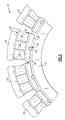
- sections 16 and 18 of the example gas turbine engine include turbine vanes 20 disposed circumferentially along a rail on the outer periphery of the support 34.
- the vanes 20 are prevented from rotating or moving about the axis 15.
- An inner air seal 36 is disposed on the support 34.
- Each of the turbine vanes 20 includes one or more airfoils 22 that direct the gas flow through the turbine segments 16 and 18.
- the support 34 includes the air seal 36 that cooperates with a flange 28 of each turbine vane 20 to prevent gas stream flow between or around the turbine vanes 20.
- the turbine vanes 20 are butted against each other and prevented from rotating on the support by an anti-rotation post 32 received in a slot 30.
- the turbine vanes 20 include an inboard segment or platform 24 and an outboard segment or platform 26 that is spaced radially outboard of the inboard segment 24.
- At least one airfoil 22 extends from the inboard segment 24 and the outboard segment 26. In the disclosed example there are three airfoils 22, however, the number of airfoils 22 in each turbine vane 20 could be more or less depending on the desired application and environment.
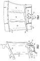
- the flange 28 extends radially inward from the inboard segment 24 and includes the slot 30.
- the example slot 30 is disposed midway between opposing ends of the flange 28.
- the slot 30 could also be disposed in other locations as is required to maintain a desired position of the turbine vane 20.
- the post 32 is received within the slot 30 and holds the turbine vane 20 in a desired circumferential position.
- the slot 30 includes an open end that provides for radial movement of the turbine vane 20 to accommodate thermal cycling during operation.
- the slot 30 is open through the flange 28. Adjacent to the flange 28 is the stationary air seal 36 that interacts with the flange 28 to prevent the leakage flow of cooling air that passes through airfoils 22. This cooling air in turn cools the airfoil 22 to operate is temperatures near its melting point.
- the slot 30 extends radially upward into the flange 28 and terminates at a back surface 42.
- the slot 30 includes the back surface 42 and two side surfaces 44A, 44B.
- the back surface 42 includes a compound radius and the two side surfaces 44A and 44B transition smoothly into the back surface through a corresponding transition region 46A, 46B.
- the back surface 42 is spaced apart a distance 38 from an end of the air seal 36 such that the slot 30 is not exposed to gas flow to create an alternate leak path in response to thermal growth encountered during engine operation.
- the slot 30 in the flange 28 can be utilized in turbine vanes which allow cooling air to pass through the airfoil, and may also be utilized in turbine vanes that do not provide cooling airfoil through the airfoil. Accordingly, the disclosed slot 30 will benefit both cooled and non-cooled turbine vanes by substantially eliminating stresses encountered during operation.
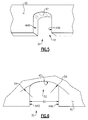
- the smooth transition of the back surface 42, through the transition regions 46A, 46B is formed as a compound radius 52.
- the example compound radius 52 includes a first radius 54 along the back surface 42 and a second radius 56 that is smaller than the first radius 54 through the transition region 46A, 46B between the back surface 42 and the side surfaces 44A, 44B.
- the first radius 52 is approximately four times larger than the second smaller radius 56. Accordingly, a ratio of the first radius 52 relative to the second radius is approximately four.
- the back surface 42 and the two side surfaces 44A, 44B are transverse the front surface 40 and back surface 50.
- the slot 30 extends entirely through the flange 28 to provide the opening for the post 32.
- the slot 30 includes a width 60 that corresponds to the post 32.
- the larger radius 54 is therefore utilized together with the second radius 56 to provide a substantially curved interior profile.
- Sharp radius corners within the slot 30 can result in a concentration of stresses that could reduce part durability, while one large radius makes it difficult to fit within desired size limitations and maintain sufficient sealing performance during engine operation.
- the example compound radius 52 provided by the first and second radii 54, and 56 reduces the stresses placed in the turbine vane 20 without degrading sealing performance.
- the example compound radius 52 eliminates sharp corners in the slot 30 and reduces mechanical stresses on the flange that improve part performance and durability.
- the application of the compound radii on the back surface 42 and the side surfaces 44A, 44B reduces or substantially eliminates the stresses encountered during operation and accompanying thermal cycling.
- the reduction in stresses provides for the extended operational life of the turbine vane 20.
Landscapes
- Engineering & Computer Science (AREA)
- Mechanical Engineering (AREA)
- General Engineering & Computer Science (AREA)
- Turbine Rotor Nozzle Sealing (AREA)
- Control Of Turbines (AREA)
Abstract

Description
- This disclosure generally relates to an interface for holding a position of a vane. More particularly, this disclosure relates to an interface surface of a position retention slot for a turbine vane.
- A gas turbine engine includes turbine vanes that are stationary and direct a flow of gases against airfoils of rotating turbine blades. The position of the turbine vanes may be maintained by including locating features on the support that is received within a portion of the turbine vane. The locating feature may be a post that extends axially from the support. The turbine vane may include a slot into which the post is received. The post and slot arrangement allow radial thermal expansion while also preventing rotation about the support. During periodic inspections, the slot is checked for signs of wear and distress. Distress can cause deterioration of the part in areas where stresses are concentrated. Accordingly, it is desirable to design and develop parts that are configured to reduce stress loads.
- A fixed vane section for a gas turbine engine includes an anti-rotation slot that receives a pin for maintaining a desired position while providing for movement due to thermal growth encountered during operation. The example anti-rotation slot includes is spaced a distance away from any air seal and includes a compound radii on inner surfaces to reduce stresses encountered during operation.
- These and other features disclosed herein can be best understood from the following specification and drawings, the following of which is a brief description.
-
-
Figure 1 is a schematic view of a gas turbine engine. -
Figure 2 is a schematic view of an example several example turbine vanes. -
Figure 3 is a partial sectional view of the example turbine vane. -
Figure 4 is a front view of the example turbine vane. -
Figure 5 is a perspective view of an example anti-rotation slot. -
Figure 6 is an enlarged front view of the example anti-rotation slot. - Referring to
Figure 1 , an example gas turbine engine is schematically shown and indicated at 10. Thegas turbine engine 10 includes acompressor section 12 where intake air is compressed and fed into acombustor section 14. In thecombustor section 14 the compressed air is mixed with fuel and ignited to generate a high energy and high velocity stream of gases. The stream of gases flows through aturbine section 16 where energy from the stream of gases is utilized to drive thecompressor section 12. Gases generated by thecombustor 14 are guided through fixed vanes withinsections - Referring to
Figure 2 ,sections turbine vanes 20 disposed circumferentially along a rail on the outer periphery of thesupport 34. Thevanes 20 are prevented from rotating or moving about theaxis 15. Aninner air seal 36 is disposed on thesupport 34. Each of the turbine vanes 20 includes one ormore airfoils 22 that direct the gas flow through theturbine segments support 34 includes theair seal 36 that cooperates with aflange 28 of eachturbine vane 20 to prevent gas stream flow between or around the turbine vanes 20. - The
turbine vanes 20 are butted against each other and prevented from rotating on the support by ananti-rotation post 32 received in aslot 30. The turbine vanes 20 include an inboard segment orplatform 24 and an outboard segment orplatform 26 that is spaced radially outboard of theinboard segment 24. At least oneairfoil 22 extends from theinboard segment 24 and theoutboard segment 26. In the disclosed example there are threeairfoils 22, however, the number ofairfoils 22 in eachturbine vane 20 could be more or less depending on the desired application and environment. - The
flange 28 extends radially inward from theinboard segment 24 and includes theslot 30. Theexample slot 30 is disposed midway between opposing ends of theflange 28. Theslot 30 could also be disposed in other locations as is required to maintain a desired position of theturbine vane 20. Thepost 32 is received within theslot 30 and holds theturbine vane 20 in a desired circumferential position. Theslot 30 includes an open end that provides for radial movement of theturbine vane 20 to accommodate thermal cycling during operation. - Referring to
Figures 3 and 4 , theslot 30 is open through theflange 28. Adjacent to theflange 28 is thestationary air seal 36 that interacts with theflange 28 to prevent the leakage flow of cooling air that passes throughairfoils 22. This cooling air in turn cools theairfoil 22 to operate is temperatures near its melting point. Theslot 30 extends radially upward into theflange 28 and terminates at aback surface 42. Theslot 30 includes theback surface 42 and twoside surfaces back surface 42 includes a compound radius and the twoside surfaces corresponding transition region back surface 42 is spaced apart adistance 38 from an end of theair seal 36 such that theslot 30 is not exposed to gas flow to create an alternate leak path in response to thermal growth encountered during engine operation. Theslot 30 in theflange 28 can be utilized in turbine vanes which allow cooling air to pass through the airfoil, and may also be utilized in turbine vanes that do not provide cooling airfoil through the airfoil. Accordingly, the disclosedslot 30 will benefit both cooled and non-cooled turbine vanes by substantially eliminating stresses encountered during operation. - Referring to
Figures 5 and 6 , the smooth transition of theback surface 42, through thetransition regions compound radius 52. Theexample compound radius 52 includes afirst radius 54 along theback surface 42 and asecond radius 56 that is smaller than thefirst radius 54 through thetransition region back surface 42 and theside surfaces first radius 52 is approximately four times larger than the secondsmaller radius 56. Accordingly, a ratio of thefirst radius 52 relative to the second radius is approximately four. Theback surface 42 and the twoside surfaces front surface 40 and back surface 50. Theslot 30 extends entirely through theflange 28 to provide the opening for thepost 32. - The
slot 30 includes a width 60 that corresponds to thepost 32. Thelarger radius 54 is therefore utilized together with thesecond radius 56 to provide a substantially curved interior profile. Sharp radius corners within theslot 30 can result in a concentration of stresses that could reduce part durability, while one large radius makes it difficult to fit within desired size limitations and maintain sufficient sealing performance during engine operation. Theexample compound radius 52 provided by the first andsecond radii turbine vane 20 without degrading sealing performance. Theexample compound radius 52 eliminates sharp corners in theslot 30 and reduces mechanical stresses on the flange that improve part performance and durability. - Accordingly the application of the compound radii on the
back surface 42 and theside surfaces turbine vane 20. - Although a preferred embodiment of this invention has been disclosed, a worker of ordinary skill in this art would recognize that certain modifications would come within the scope of this invention. For that reason, the following claims should be studied to determine the true scope and content of this invention.
Claims (15)
- A turbine vane (20) comprising:a platform segment (24);an airfoil segment (22) extending from the platform segment (24); anda flange portion (28) extending from the platform segment (24), the flange portion (28) including a slot (30) with a compound radius over at least a portion of a surface that engages an alignment post (32).
- The turbine vane as recited in claim 1, wherein the slot (30) is defined by a back surface (42) and two side surfaces (44A,44B), wherein the back surface (42) comprises a first radius (54), and a transition region (46A,46B) between the back surface (42) and the two side surfaces (44A,44B), the transition region (46A,46B) comprising a second radius (56) that is smaller than the first radius (54).
- The turbine vane as recited in claim 2, wherein the slot (30) is further defined by a forward surface (40), with the back surface (42) and the two side surfaces (44A,44B) disposed transverse relative to the forward surface (40).
- The turbine vane as recited in claim 2 or 3, wherein the back surface (42) of the slot (30) is spaced radially from a top surface of the platform (24).
- The turbine vane as recited in any preceding claim, wherein the airfoil segment (22) comprises at least two airfoils (22) extending from the platform segment (24).
- The turbine vane as recited in claim 5, including an upper platform segment (26) attached to the at least two airfoils (22).
- The turbine vane as recited in any preceding claim, wherein the slot (30) comprises one slot (30) disposed at an intermediate position between ends of the flange portion (28).
- The turbine vane as recited in any preceding claim, wherein the platform (24) includes at least a front flange (28) and a rear flange spaced axially apart from the front flange (28).
- A turbine vane (20) comprising:an inboard segment (24) and an outboard segment (26) that is spaced radially apart from the inboard segment (24);at least one airfoil (22) extending radially between the inboard and outboard segments (24,26); andan inner flange (28) including a portion that includes an alignment slot (30), wherein the alignment slot (30) comprises a back surface (42) that includes a compound radius.
- The turbine vane as recited in claim 9, wherein the slot compound radius comprises a first radius (54) and at least one second radius (56) smaller than the first radius(54).
- The turbine vane as recited in claim 10, wherein the slot (30) includes first and second sides (44A,44B) and a transition region (46A,46B) between the back surface (42) and the side surfaces (44A,44B) with the second radius (56) disposed in the transition region (46A,46B).
- The turbine vane as recited in any of claims 9 to 11, wherein the back surface (42) is spaced a distance radially inward from the inboard segment (24).
- The turbine vane as recited in any of claims 9 to 12, wherein the slot (30) comprises an open end opposite the back surface (42).
- A method of forming a turbine vane (20) including the steps of:forming an inboard segment (24) and an outboard segment (26) that is spaced radially apart from the inboard segment (24);forming an airfoil (22) extending radially between the inboard and outboard segments (24,26); andforming a compound radius (54,56) on a back surface (42) of a slot (30) within an inner flange (28) extending from the inboard segment (24).
- The method as recited in claim 14, including forming the slot (30) with an open end opposite the back surface (42) and a transition surface (46A,46B) between the back surface (42) and two side surfaces (44A,44b), and optionally including the step of forming the compound radius with a first radius (54) of the back surface (42) and second radius (56) at the transition portions (46A,46B) between the back surface (42) and each of the two side surfaces (44A,44B).
Applications Claiming Priority (1)
| Application Number | Priority Date | Filing Date | Title |
|---|---|---|---|
| US12/749,971 US8794911B2 (en) | 2010-03-30 | 2010-03-30 | Anti-rotation slot for turbine vane |
Publications (3)
| Publication Number | Publication Date |
|---|---|
| EP2372097A2 true EP2372097A2 (en) | 2011-10-05 |
| EP2372097A3 EP2372097A3 (en) | 2014-11-12 |
| EP2372097B1 EP2372097B1 (en) | 2020-03-18 |
Family
ID=43858240
Family Applications (1)
| Application Number | Title | Priority Date | Filing Date |
|---|---|---|---|
| EP11160403.9A Active EP2372097B1 (en) | 2010-03-30 | 2011-03-30 | Turbine vane with anti-rotation slot |
Country Status (2)
| Country | Link |
|---|---|
| US (1) | US8794911B2 (en) |
| EP (1) | EP2372097B1 (en) |
Cited By (1)
| Publication number | Priority date | Publication date | Assignee | Title |
|---|---|---|---|---|
| WO2021023470A1 (en) | 2019-08-06 | 2021-02-11 | Safran Aircraft Engines | Aircraft turboshaft engine compressor comprising a device for immobilising a retaining ring |
Families Citing this family (7)
| Publication number | Priority date | Publication date | Assignee | Title |
|---|---|---|---|---|
| US9416673B2 (en) * | 2012-01-17 | 2016-08-16 | United Technologies Corporation | Hybrid inner air seal for gas turbine engines |
| US9051849B2 (en) | 2012-02-13 | 2015-06-09 | United Technologies Corporation | Anti-rotation stator segments |
| US9896971B2 (en) * | 2012-09-28 | 2018-02-20 | United Technologies Corporation | Lug for preventing rotation of a stator vane arrangement relative to a turbine engine case |
| US10138749B2 (en) | 2016-03-16 | 2018-11-27 | United Technologies Corporation | Seal anti-rotation feature |
| US20190078469A1 (en) * | 2017-09-11 | 2019-03-14 | United Technologies Corporation | Fan exit stator assembly retention system |
| US10865650B2 (en) | 2017-09-12 | 2020-12-15 | Raytheon Technologies Corporation | Stator vane support with anti-rotation features |
| DE102020203840A1 (en) * | 2020-03-25 | 2021-09-30 | MTU Aero Engines AG | Gas turbine component |
Family Cites Families (17)
| Publication number | Priority date | Publication date | Assignee | Title |
|---|---|---|---|---|
| US3362681A (en) * | 1966-08-24 | 1968-01-09 | Gen Electric | Turbine cooling |
| BE755567A (en) * | 1969-12-01 | 1971-02-15 | Gen Electric | FIXED VANE STRUCTURE, FOR GAS TURBINE ENGINE AND ASSOCIATED TEMPERATURE ADJUSTMENT ARRANGEMENT |
| US4017213A (en) * | 1975-10-14 | 1977-04-12 | United Technologies Corporation | Turbomachinery vane or blade with cooled platforms |
| US4566851A (en) | 1984-05-11 | 1986-01-28 | United Technologies Corporation | First stage turbine vane support structure |
| US4720236A (en) * | 1984-12-21 | 1988-01-19 | United Technologies Corporation | Coolable stator assembly for a gas turbine engine |
| US4749333A (en) | 1986-05-12 | 1988-06-07 | The United States Of America As Represented By The Secretary Of The Air Force | Vane platform sealing and retention means |
| US4856963A (en) | 1988-03-23 | 1989-08-15 | United Technologies Corporation | Stator assembly for an axial flow rotary machine |
| US5004402A (en) | 1989-09-05 | 1991-04-02 | United Technologies Corporation | Axial compressor stator construction |
| US5141394A (en) * | 1990-10-10 | 1992-08-25 | Westinghouse Electric Corp. | Apparatus and method for supporting a vane segment in a gas turbine |
| US5211536A (en) | 1991-05-13 | 1993-05-18 | General Electric Company | Boltless turbine nozzle/stationary seal mounting |
| CA2070511C (en) | 1991-07-22 | 2001-08-21 | Steven Milo Toborg | Turbine nozzle support |
| US5176496A (en) | 1991-09-27 | 1993-01-05 | General Electric Company | Mounting arrangements for turbine nozzles |
| US5709530A (en) | 1996-09-04 | 1998-01-20 | United Technologies Corporation | Gas turbine vane seal |
| US6893222B2 (en) * | 2003-02-10 | 2005-05-17 | United Technologies Corporation | Turbine balancing |
| US7032904B2 (en) | 2003-08-13 | 2006-04-25 | United Technologies Corporation | Inner air seal anti-rotation device |
| US7144218B2 (en) | 2004-04-19 | 2006-12-05 | United Technologies Corporation | Anti-rotation lock |
| US8360716B2 (en) * | 2010-03-23 | 2013-01-29 | United Technologies Corporation | Nozzle segment with reduced weight flange |
-
2010
- 2010-03-30 US US12/749,971 patent/US8794911B2/en active Active
-
2011
- 2011-03-30 EP EP11160403.9A patent/EP2372097B1/en active Active
Non-Patent Citations (1)
| Title |
|---|
| None |
Cited By (4)
| Publication number | Priority date | Publication date | Assignee | Title |
|---|---|---|---|---|
| WO2021023470A1 (en) | 2019-08-06 | 2021-02-11 | Safran Aircraft Engines | Aircraft turboshaft engine compressor comprising a device for immobilising a retaining ring |
| FR3099792A1 (en) * | 2019-08-06 | 2021-02-12 | Safran Aircraft Engines | Aircraft turbine engine compressor comprising a device for locking a retaining ring |
| CN114174651A (en) * | 2019-08-06 | 2022-03-11 | 赛峰飞机发动机公司 | Compressor of an aircraft turboshaft engine comprising means for fixing a retaining ring |
| US11859508B2 (en) | 2019-08-06 | 2024-01-02 | Safran Aircraft Engines | Aircraft turboshaft engine compressor comprising a device for immobilising a retaining annulus |
Also Published As
| Publication number | Publication date |
|---|---|
| US8794911B2 (en) | 2014-08-05 |
| EP2372097B1 (en) | 2020-03-18 |
| EP2372097A3 (en) | 2014-11-12 |
| US20110243722A1 (en) | 2011-10-06 |
Similar Documents
| Publication | Publication Date | Title |
|---|---|---|
| US8794911B2 (en) | Anti-rotation slot for turbine vane | |
| EP2984296B1 (en) | Blade outer air seal with secondary air sealing | |
| US9115596B2 (en) | Blade outer air seal having anti-rotation feature | |
| EP3730744A1 (en) | Seal for platform rail of turbine vane | |
| EP2875223B1 (en) | Blade outer air seal having inward pointing extension | |
| US9995157B2 (en) | Gas turbine engine turbine vane platform cooling | |
| US20150098829A1 (en) | Shroud assembly and seal for a gas turbine engine | |
| EP3594453A1 (en) | Feather seal assembly | |
| US9243508B2 (en) | System and method for recirculating a hot gas flowing through a gas turbine | |
| EP3090140B1 (en) | Blade outer air seal with secondary air sealing | |
| EP2938839B1 (en) | Blade outer air seal having shiplap structure | |
| EP3594452A1 (en) | Segmented rim seal spacer for a gas turbine engine | |
| EP2447475B1 (en) | Airfoil attachement arrangement | |
| NL2002312C2 (en) | Cooled turbine nozzle segment. | |
| US8769816B2 (en) | Method of assembling a gas turbine engine | |
| US20120269622A1 (en) | Turbine vane and gas turbine | |
| EP3088662A1 (en) | Multi-stage turbine interstage seal and method of assembly | |
| US9850771B2 (en) | Gas turbine engine sealing arrangement | |
| US9605553B2 (en) | Turbine seal system and method | |
| EP3246535B1 (en) | Turbine vane gusset | |
| EP3483397B1 (en) | Support rail truss for gas turbine engines |
Legal Events
| Date | Code | Title | Description |
|---|---|---|---|
| PUAI | Public reference made under article 153(3) epc to a published international application that has entered the european phase |
Free format text: ORIGINAL CODE: 0009012 |
|
| AK | Designated contracting states |
Kind code of ref document: A2 Designated state(s): AL AT BE BG CH CY CZ DE DK EE ES FI FR GB GR HR HU IE IS IT LI LT LU LV MC MK MT NL NO PL PT RO RS SE SI SK SM TR |
|
| AX | Request for extension of the european patent |
Extension state: BA ME |
|
| PUAL | Search report despatched |
Free format text: ORIGINAL CODE: 0009013 |
|
| AK | Designated contracting states |
Kind code of ref document: A3 Designated state(s): AL AT BE BG CH CY CZ DE DK EE ES FI FR GB GR HR HU IE IS IT LI LT LU LV MC MK MT NL NO PL PT RO RS SE SI SK SM TR |
|
| AX | Request for extension of the european patent |
Extension state: BA ME |
|
| RIC1 | Information provided on ipc code assigned before grant |
Ipc: F01D 9/04 20060101AFI20141009BHEP |
|
| 17P | Request for examination filed |
Effective date: 20150512 |
|
| RBV | Designated contracting states (corrected) |
Designated state(s): AL AT BE BG CH CY CZ DE DK EE ES FI FR GB GR HR HU IE IS IT LI LT LU LV MC MK MT NL NO PL PT RO RS SE SI SK SM TR |
|
| 17Q | First examination report despatched |
Effective date: 20160711 |
|
| RAP1 | Party data changed (applicant data changed or rights of an application transferred) |
Owner name: UNITED TECHNOLOGIES CORPORATION |
|
| STAA | Information on the status of an ep patent application or granted ep patent |
Free format text: STATUS: EXAMINATION IS IN PROGRESS |
|
| GRAP | Despatch of communication of intention to grant a patent |
Free format text: ORIGINAL CODE: EPIDOSNIGR1 |
|
| STAA | Information on the status of an ep patent application or granted ep patent |
Free format text: STATUS: GRANT OF PATENT IS INTENDED |
|
| INTG | Intention to grant announced |
Effective date: 20191031 |
|
| GRAS | Grant fee paid |
Free format text: ORIGINAL CODE: EPIDOSNIGR3 |
|
| GRAA | (expected) grant |
Free format text: ORIGINAL CODE: 0009210 |
|
| STAA | Information on the status of an ep patent application or granted ep patent |
Free format text: STATUS: THE PATENT HAS BEEN GRANTED |
|
| AK | Designated contracting states |
Kind code of ref document: B1 Designated state(s): AL AT BE BG CH CY CZ DE DK EE ES FI FR GB GR HR HU IE IS IT LI LT LU LV MC MK MT NL NO PL PT RO RS SE SI SK SM TR |
|
| REG | Reference to a national code |
Ref country code: GB Ref legal event code: FG4D |
|
| REG | Reference to a national code |
Ref country code: DE Ref legal event code: R096 Ref document number: 602011065629 Country of ref document: DE |
|
| REG | Reference to a national code |
Ref country code: AT Ref legal event code: REF Ref document number: 1246114 Country of ref document: AT Kind code of ref document: T Effective date: 20200415 Ref country code: IE Ref legal event code: FG4D |
|
| PG25 | Lapsed in a contracting state [announced via postgrant information from national office to epo] |
Ref country code: NO Free format text: LAPSE BECAUSE OF FAILURE TO SUBMIT A TRANSLATION OF THE DESCRIPTION OR TO PAY THE FEE WITHIN THE PRESCRIBED TIME-LIMIT Effective date: 20200618 Ref country code: RS Free format text: LAPSE BECAUSE OF FAILURE TO SUBMIT A TRANSLATION OF THE DESCRIPTION OR TO PAY THE FEE WITHIN THE PRESCRIBED TIME-LIMIT Effective date: 20200318 Ref country code: FI Free format text: LAPSE BECAUSE OF FAILURE TO SUBMIT A TRANSLATION OF THE DESCRIPTION OR TO PAY THE FEE WITHIN THE PRESCRIBED TIME-LIMIT Effective date: 20200318 |
|
| REG | Reference to a national code |
Ref country code: NL Ref legal event code: MP Effective date: 20200318 |
|
| PG25 | Lapsed in a contracting state [announced via postgrant information from national office to epo] |
Ref country code: LV Free format text: LAPSE BECAUSE OF FAILURE TO SUBMIT A TRANSLATION OF THE DESCRIPTION OR TO PAY THE FEE WITHIN THE PRESCRIBED TIME-LIMIT Effective date: 20200318 Ref country code: SE Free format text: LAPSE BECAUSE OF FAILURE TO SUBMIT A TRANSLATION OF THE DESCRIPTION OR TO PAY THE FEE WITHIN THE PRESCRIBED TIME-LIMIT Effective date: 20200318 Ref country code: GR Free format text: LAPSE BECAUSE OF FAILURE TO SUBMIT A TRANSLATION OF THE DESCRIPTION OR TO PAY THE FEE WITHIN THE PRESCRIBED TIME-LIMIT Effective date: 20200619 Ref country code: BG Free format text: LAPSE BECAUSE OF FAILURE TO SUBMIT A TRANSLATION OF THE DESCRIPTION OR TO PAY THE FEE WITHIN THE PRESCRIBED TIME-LIMIT Effective date: 20200618 Ref country code: HR Free format text: LAPSE BECAUSE OF FAILURE TO SUBMIT A TRANSLATION OF THE DESCRIPTION OR TO PAY THE FEE WITHIN THE PRESCRIBED TIME-LIMIT Effective date: 20200318 |
|
| REG | Reference to a national code |
Ref country code: LT Ref legal event code: MG4D |
|
| PG25 | Lapsed in a contracting state [announced via postgrant information from national office to epo] |
Ref country code: NL Free format text: LAPSE BECAUSE OF FAILURE TO SUBMIT A TRANSLATION OF THE DESCRIPTION OR TO PAY THE FEE WITHIN THE PRESCRIBED TIME-LIMIT Effective date: 20200318 |
|
| PG25 | Lapsed in a contracting state [announced via postgrant information from national office to epo] |
Ref country code: IS Free format text: LAPSE BECAUSE OF FAILURE TO SUBMIT A TRANSLATION OF THE DESCRIPTION OR TO PAY THE FEE WITHIN THE PRESCRIBED TIME-LIMIT Effective date: 20200718 Ref country code: SK Free format text: LAPSE BECAUSE OF FAILURE TO SUBMIT A TRANSLATION OF THE DESCRIPTION OR TO PAY THE FEE WITHIN THE PRESCRIBED TIME-LIMIT Effective date: 20200318 Ref country code: RO Free format text: LAPSE BECAUSE OF FAILURE TO SUBMIT A TRANSLATION OF THE DESCRIPTION OR TO PAY THE FEE WITHIN THE PRESCRIBED TIME-LIMIT Effective date: 20200318 Ref country code: CZ Free format text: LAPSE BECAUSE OF FAILURE TO SUBMIT A TRANSLATION OF THE DESCRIPTION OR TO PAY THE FEE WITHIN THE PRESCRIBED TIME-LIMIT Effective date: 20200318 Ref country code: SM Free format text: LAPSE BECAUSE OF FAILURE TO SUBMIT A TRANSLATION OF THE DESCRIPTION OR TO PAY THE FEE WITHIN THE PRESCRIBED TIME-LIMIT Effective date: 20200318 Ref country code: LT Free format text: LAPSE BECAUSE OF FAILURE TO SUBMIT A TRANSLATION OF THE DESCRIPTION OR TO PAY THE FEE WITHIN THE PRESCRIBED TIME-LIMIT Effective date: 20200318 Ref country code: EE Free format text: LAPSE BECAUSE OF FAILURE TO SUBMIT A TRANSLATION OF THE DESCRIPTION OR TO PAY THE FEE WITHIN THE PRESCRIBED TIME-LIMIT Effective date: 20200318 Ref country code: PT Free format text: LAPSE BECAUSE OF FAILURE TO SUBMIT A TRANSLATION OF THE DESCRIPTION OR TO PAY THE FEE WITHIN THE PRESCRIBED TIME-LIMIT Effective date: 20200812 |
|
| REG | Reference to a national code |
Ref country code: CH Ref legal event code: PL |
|
| REG | Reference to a national code |
Ref country code: AT Ref legal event code: MK05 Ref document number: 1246114 Country of ref document: AT Kind code of ref document: T Effective date: 20200318 |
|
| REG | Reference to a national code |
Ref country code: DE Ref legal event code: R097 Ref document number: 602011065629 Country of ref document: DE |
|
| REG | Reference to a national code |
Ref country code: BE Ref legal event code: MM Effective date: 20200331 |
|
| PG25 | Lapsed in a contracting state [announced via postgrant information from national office to epo] |
Ref country code: MC Free format text: LAPSE BECAUSE OF FAILURE TO SUBMIT A TRANSLATION OF THE DESCRIPTION OR TO PAY THE FEE WITHIN THE PRESCRIBED TIME-LIMIT Effective date: 20200318 Ref country code: LU Free format text: LAPSE BECAUSE OF NON-PAYMENT OF DUE FEES Effective date: 20200330 |
|
| PLBE | No opposition filed within time limit |
Free format text: ORIGINAL CODE: 0009261 |
|
| STAA | Information on the status of an ep patent application or granted ep patent |
Free format text: STATUS: NO OPPOSITION FILED WITHIN TIME LIMIT |
|
| PG25 | Lapsed in a contracting state [announced via postgrant information from national office to epo] |
Ref country code: IE Free format text: LAPSE BECAUSE OF NON-PAYMENT OF DUE FEES Effective date: 20200330 Ref country code: CH Free format text: LAPSE BECAUSE OF NON-PAYMENT OF DUE FEES Effective date: 20200331 Ref country code: ES Free format text: LAPSE BECAUSE OF FAILURE TO SUBMIT A TRANSLATION OF THE DESCRIPTION OR TO PAY THE FEE WITHIN THE PRESCRIBED TIME-LIMIT Effective date: 20200318 Ref country code: DK Free format text: LAPSE BECAUSE OF FAILURE TO SUBMIT A TRANSLATION OF THE DESCRIPTION OR TO PAY THE FEE WITHIN THE PRESCRIBED TIME-LIMIT Effective date: 20200318 Ref country code: AT Free format text: LAPSE BECAUSE OF FAILURE TO SUBMIT A TRANSLATION OF THE DESCRIPTION OR TO PAY THE FEE WITHIN THE PRESCRIBED TIME-LIMIT Effective date: 20200318 Ref country code: IT Free format text: LAPSE BECAUSE OF FAILURE TO SUBMIT A TRANSLATION OF THE DESCRIPTION OR TO PAY THE FEE WITHIN THE PRESCRIBED TIME-LIMIT Effective date: 20200318 Ref country code: LI Free format text: LAPSE BECAUSE OF NON-PAYMENT OF DUE FEES Effective date: 20200331 |
|
| 26N | No opposition filed |
Effective date: 20201221 |
|
| PG25 | Lapsed in a contracting state [announced via postgrant information from national office to epo] |
Ref country code: PL Free format text: LAPSE BECAUSE OF FAILURE TO SUBMIT A TRANSLATION OF THE DESCRIPTION OR TO PAY THE FEE WITHIN THE PRESCRIBED TIME-LIMIT Effective date: 20200318 Ref country code: BE Free format text: LAPSE BECAUSE OF NON-PAYMENT OF DUE FEES Effective date: 20200331 |
|
| PG25 | Lapsed in a contracting state [announced via postgrant information from national office to epo] |
Ref country code: SI Free format text: LAPSE BECAUSE OF FAILURE TO SUBMIT A TRANSLATION OF THE DESCRIPTION OR TO PAY THE FEE WITHIN THE PRESCRIBED TIME-LIMIT Effective date: 20200318 |
|
| PG25 | Lapsed in a contracting state [announced via postgrant information from national office to epo] |
Ref country code: TR Free format text: LAPSE BECAUSE OF FAILURE TO SUBMIT A TRANSLATION OF THE DESCRIPTION OR TO PAY THE FEE WITHIN THE PRESCRIBED TIME-LIMIT Effective date: 20200318 Ref country code: MT Free format text: LAPSE BECAUSE OF FAILURE TO SUBMIT A TRANSLATION OF THE DESCRIPTION OR TO PAY THE FEE WITHIN THE PRESCRIBED TIME-LIMIT Effective date: 20200318 Ref country code: CY Free format text: LAPSE BECAUSE OF FAILURE TO SUBMIT A TRANSLATION OF THE DESCRIPTION OR TO PAY THE FEE WITHIN THE PRESCRIBED TIME-LIMIT Effective date: 20200318 |
|
| PG25 | Lapsed in a contracting state [announced via postgrant information from national office to epo] |
Ref country code: MK Free format text: LAPSE BECAUSE OF FAILURE TO SUBMIT A TRANSLATION OF THE DESCRIPTION OR TO PAY THE FEE WITHIN THE PRESCRIBED TIME-LIMIT Effective date: 20200318 Ref country code: AL Free format text: LAPSE BECAUSE OF FAILURE TO SUBMIT A TRANSLATION OF THE DESCRIPTION OR TO PAY THE FEE WITHIN THE PRESCRIBED TIME-LIMIT Effective date: 20200318 |
|
| REG | Reference to a national code |
Ref country code: DE Ref legal event code: R081 Ref document number: 602011065629 Country of ref document: DE Owner name: RAYTHEON TECHNOLOGIES CORPORATION (N.D.GES.D.S, US Free format text: FORMER OWNER: UNITED TECHNOLOGIES CORPORATION, FARMINGTON, CONN., US Ref country code: DE Ref legal event code: R081 Ref document number: 602011065629 Country of ref document: DE Owner name: RTX CORPORATION (N.D.GES.D. STAATES DELAWARE),, US Free format text: FORMER OWNER: UNITED TECHNOLOGIES CORPORATION, FARMINGTON, CONN., US |
|
| P01 | Opt-out of the competence of the unified patent court (upc) registered |
Effective date: 20230519 |
|
| REG | Reference to a national code |
Ref country code: DE Ref legal event code: R081 Ref document number: 602011065629 Country of ref document: DE Owner name: RTX CORPORATION (N.D.GES.D. STAATES DELAWARE),, US Free format text: FORMER OWNER: RAYTHEON TECHNOLOGIES CORPORATION (N.D.GES.D.STAATES DELAWARE), ARLINGTON, VA, US |
|
| PGFP | Annual fee paid to national office [announced via postgrant information from national office to epo] |
Ref country code: GB Payment date: 20260220 Year of fee payment: 16 |
|
| PGFP | Annual fee paid to national office [announced via postgrant information from national office to epo] |
Ref country code: DE Payment date: 20260219 Year of fee payment: 16 |
|
| PGFP | Annual fee paid to national office [announced via postgrant information from national office to epo] |
Ref country code: FR Payment date: 20260219 Year of fee payment: 16 |