EP2372094A2 - Non-Integral Platform and Damper for a gas turbine engine blade - Google Patents
Non-Integral Platform and Damper for a gas turbine engine blade Download PDFInfo
- Publication number
- EP2372094A2 EP2372094A2 EP11161061A EP11161061A EP2372094A2 EP 2372094 A2 EP2372094 A2 EP 2372094A2 EP 11161061 A EP11161061 A EP 11161061A EP 11161061 A EP11161061 A EP 11161061A EP 2372094 A2 EP2372094 A2 EP 2372094A2
- Authority
- EP
- European Patent Office
- Prior art keywords
- damper
- blade
- seal
- recited
- section
- Prior art date
- Legal status (The legal status is an assumption and is not a legal conclusion. Google has not performed a legal analysis and makes no representation as to the accuracy of the status listed.)
- Granted
Links
Images

Classifications
-
- F—MECHANICAL ENGINEERING; LIGHTING; HEATING; WEAPONS; BLASTING
- F01—MACHINES OR ENGINES IN GENERAL; ENGINE PLANTS IN GENERAL; STEAM ENGINES
- F01D—NON-POSITIVE DISPLACEMENT MACHINES OR ENGINES, e.g. STEAM TURBINES
- F01D5/00—Blades; Blade-carrying members; Heating, heat-insulating, cooling or antivibration means on the blades or the members
- F01D5/12—Blades
- F01D5/26—Antivibration means not restricted to blade form or construction or to blade-to-blade connections or to the use of particular materials
-
- F—MECHANICAL ENGINEERING; LIGHTING; HEATING; WEAPONS; BLASTING
- F01—MACHINES OR ENGINES IN GENERAL; ENGINE PLANTS IN GENERAL; STEAM ENGINES
- F01D—NON-POSITIVE DISPLACEMENT MACHINES OR ENGINES, e.g. STEAM TURBINES
- F01D11/00—Preventing or minimising internal leakage of working-fluid, e.g. between stages
- F01D11/005—Sealing means between non relatively rotating elements
- F01D11/006—Sealing the gap between rotor blades or blades and rotor
- F01D11/008—Sealing the gap between rotor blades or blades and rotor by spacer elements between the blades, e.g. independent interblade platforms
-
- F—MECHANICAL ENGINEERING; LIGHTING; HEATING; WEAPONS; BLASTING
- F01—MACHINES OR ENGINES IN GENERAL; ENGINE PLANTS IN GENERAL; STEAM ENGINES
- F01D—NON-POSITIVE DISPLACEMENT MACHINES OR ENGINES, e.g. STEAM TURBINES
- F01D11/00—Preventing or minimising internal leakage of working-fluid, e.g. between stages
- F01D11/005—Sealing means between non relatively rotating elements
- F01D11/006—Sealing the gap between rotor blades or blades and rotor
-
- F—MECHANICAL ENGINEERING; LIGHTING; HEATING; WEAPONS; BLASTING
- F05—INDEXING SCHEMES RELATING TO ENGINES OR PUMPS IN VARIOUS SUBCLASSES OF CLASSES F01-F04
- F05D—INDEXING SCHEME FOR ASPECTS RELATING TO NON-POSITIVE-DISPLACEMENT MACHINES OR ENGINES, GAS-TURBINES OR JET-PROPULSION PLANTS
- F05D2220/00—Application
- F05D2220/30—Application in turbines
- F05D2220/36—Application in turbines specially adapted for the fan of turbofan engines
-
- Y—GENERAL TAGGING OF NEW TECHNOLOGICAL DEVELOPMENTS; GENERAL TAGGING OF CROSS-SECTIONAL TECHNOLOGIES SPANNING OVER SEVERAL SECTIONS OF THE IPC; TECHNICAL SUBJECTS COVERED BY FORMER USPC CROSS-REFERENCE ART COLLECTIONS [XRACs] AND DIGESTS
- Y02—TECHNOLOGIES OR APPLICATIONS FOR MITIGATION OR ADAPTATION AGAINST CLIMATE CHANGE
- Y02T—CLIMATE CHANGE MITIGATION TECHNOLOGIES RELATED TO TRANSPORTATION
- Y02T50/00—Aeronautics or air transport
- Y02T50/60—Efficient propulsion technologies, e.g. for aircraft
-
- Y—GENERAL TAGGING OF NEW TECHNOLOGICAL DEVELOPMENTS; GENERAL TAGGING OF CROSS-SECTIONAL TECHNOLOGIES SPANNING OVER SEVERAL SECTIONS OF THE IPC; TECHNICAL SUBJECTS COVERED BY FORMER USPC CROSS-REFERENCE ART COLLECTIONS [XRACs] AND DIGESTS
- Y10—TECHNICAL SUBJECTS COVERED BY FORMER USPC
- Y10S—TECHNICAL SUBJECTS COVERED BY FORMER USPC CROSS-REFERENCE ART COLLECTIONS [XRACs] AND DIGESTS
- Y10S416/00—Fluid reaction surfaces, i.e. impellers
- Y10S416/50—Vibration damping features
Definitions
- the present disclosure relates to gas turbine engines and, more particularly, to damping mechanisms which reduce vibratory stress levels in the rotor blades thereof.
- Gas turbine engines typically have rows of circumferentially spaced blades mounted on respective rotor disks for rotation about an engine axis.
- Advanced configurations feature shroudless hollow airfoils manufactured of light weight materials.
- the blades are designed to high tolerances to accommodate significant operational requirements such as cross-winds and inlet distortion. These requirements result in blades that may be prone to high vibratory responses and possible aeroelastic instability within some operational speed ranges. To mitigate these effects, the blades may be damped.
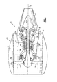
- Figure 1 illustrates a general schematic view of a gas turbine engine 10 such as a gas turbine engine for propulsion.
- the exemplary engine 10 in the disclosed non-limiting embodiment is in the form of a two spool high bypass turbofan engine. While a particular type of gas turbine engine is illustrated, it should be understood that the disclosure is applicable to other gas turbine engine configurations, including, for example, gas turbines for power generation, turbojet engines, low bypass turbofan engines, turboshaft engines, etc.
- the engine 10 includes a core engine section that houses a low spool 14 and high spool 24.
- the low spool 14 includes a low pressure compressor 16 and a low pressure turbine 18.
- the core engine section drives a fan section 20 connected to the low spool 14 either directly or through a gear train.
- the high spool 24 includes a high pressure compressor 26 and high pressure turbine 28.
- a combustor 30 is arranged between the high pressure compressor 26 and high pressure turbine 28.
- the low and high spools 14, 24 rotate about an engine axis of rotation A.
- the exemplary engine 10 is mounted within a nacelle assembly 32 defined by a core nacelle 34 and a fan nacelle 36.
- the bypass flow fan air is discharged through a fan nozzle section 38 generally defined between the core nacelle 34 and a fan nacelle 36.
- Air compressed in the compressor 16, 26 is mixed with fuel, burned in the combustor 30, and expanded in the turbines 18, 28.
- the air compressed in the compressors 16, 18 and the fuel mixture expanded in the turbines 18, 28 may be referred to as a hot gas stream along a core gas path.
- the core exhaust gases are discharged from the core engine through a core exhaust nozzle 40 generally defined between the core nacelle 34 and a center plug 42 disposed coaxially therein around an engine longitudinal centerline axis A.
- the fan section 20 includes a plurality of circumferentially spaced fan blades 44 which may be made of a high-strength, low weight material such as an aluminum alloy, titanium alloy or combinations therof.
- An annular blade containment structure 46 is typically disposed within a fan case 48 which circumferentially surrounds the path of the fan blades 44 to receive blade fragments which may be accidentally released and retained so as to prevent formation of free projectiles exterior to fan jet engine 10.
- the compressor 16, 26 includes alternate rows of rotary airfoils or blades 50 mounted to disks 52 and static airfoils or vanes 54 which at least partially define a compressor stage. It should be understood that a multiple of disks 52 may be contained within each engine section and that although a single fan stage is illustrated and described in the disclosed embodiment, other stages which have other blades inclusive of fan blades, high pressure compressor blades and low pressure compressor blades may also benefit herefrom.
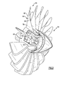
- each fan blade 44 generally includes an innermost root portion 60, an intermediate portion 62, and an outermost airfoil portion 64.
- the root portion 60 defines an attachment such as an inverted "fir tree"-like shape, bulb, or dovetail so the fan blade 44 is slidably received in a complementary configured recess provided in a fan rotor disk 52F ( Figure 3 ).
- the intermediate portion 62 generally separates the root portion 60 and the airfoil portion 64 to generally define an inner boundary of the air flow path.
- the airfoil portion 64 defines a blade chord between a leading edge 66, which may be swept forward and a trailing edge 68.
- a concave suction side 70 and a convex pressure side 72 are defined between the leading edge 66 and the trailing edge 68.
- a fan blade 44 is illustrated in the disclosed non-limiting embodiment, it should be understood that compressor blades, turbofan blades, turboprop propeller blades, tilt rotor props and other airfoils may benefit herefrom.
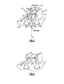
- a flow path seal assembly 80 includes a support 82, a platform 84, a flowpath seal 86A, 86B and a damper 88A, 88B.
- the flow path seal assembly 80 is mounted between each adjacent fan blade 44 to provide a flow path seal adjacent an intermediate portion 62 to define an inner diameter flow path. That is, the flow path seal assembly 80 is repeated between each pair of adjacent blades 44 around disk 52F.
- the support 82 includes a root portion 90A that defines an attachment such as an inverted "fir tree”-like shape, bulb, or dovetail so the support 82 is slidably received in a complementary configured recess 92A provided in the disk 52F.
- the support 82 also includes a tip portion 90B opposite the root portion 90A that defines an attachment such as an inverted "fir tree”-like shape, bulb, or dovetail so the platform 84 is slidably received onto the support 82 in a complementary configured recess 92B provided in the platform 84. That is, the platform 84 is displaced from the disk 52F.
- the flowpath seals 86A, 86B and the dampers 88A, 88B are mounted to the platform 84 through, for example, continuous welds, mechanical fasteners or various combinations thereof.
- the flowpath seals 86A, 86B and the dampers 88A, 88B extend from each side of the platform 84 to engage the adjacent fan blades 44 to cover at least a portion of the intermediate portion 62 of the fan blade 44 to ensure aerodynamic efficiency and damp the fan blades 44 for fundamental modes of vibration namely, first bending, second bending, and first torsion modes.
- the flowpath seals 86A, 86B define the inner boundary of the fan section 20 flow path.
- the flowpath seals 86A, 86B define a minimal gap or just barely contact the fan blade 44.
- the dampers 88A, 88B contact and ride upon the fan blade 44 as the fan blade 44 deforms in the particular vibration mode.
- the thickness and curvature of the dampers 88A, 88B are manufactured of a sheet metal to provide a stiffness and sufficient normal load against the intermediate portion 62 of the fan blade 44 that, in one non-limiting embodiment, is on the order of 20 to 40 1bs/inches.
- the centrifugal forces of the fan section 20 tends to load the dampers 88A, 88B against the fan blade 44 and the deformation thereof tends to create slippage in the radial direction.
- the dampers 88A, 88B are optimized for curvature and thickness to provide a normal load for best stress reduction.
- the normal load from the dampers 88A, 88B on the respective fan blades 44 is due to centrifugal loading ( Figure 4 ). Slippage of the dampers 88A, 88B against the respective fan blade 44 occurs when the elastic force in the dampers 88A, 88B exceeds the friction force at the contact interface.
- the damper forces at the interface are generated due to the centrifugal loading as well as the motion of the fan blade 44. These forces are designated as n [r] as they vary with the radial location on the fan blade 44.
- the fan blade motion will impart a radial deflection w[r] at the contact interface. These deflections will tend to stretch or contract the damper 88B to generate internal elastic forces in the damper 88B because of the damper stiffness k[r].
- the damper 88B ( Figure 4 ) will remain fixed relative to the fan blade 44 as long as the damper elastic force k[r] x w[r] is less than the friction force ⁇ n[r].
- the elastic force in the damper 88B will increase beyond the friction force leading to a slip at the contact interface. With the repeated vibratory motion, energy is dissipated in the form of frictional heating.
- damper assembly 80' includes dampers 88'A, 88'B.
- Each damper 88'A, 88'B provides a relatively thick wall section 100 similar to 88'A, 88'B with a blunt end 102.
- the blunt end 102 provides for a more localized contact with the fan blade 44.
- the damper assembly 80' functions on the same basic principles as the damper assembly 80 discussed above with regard to the slip force in relation to the friction force at the interface between the damper 88'A, 88'B, and the fan blade 44.
- the damper 88' increase in thickness and cross section to provide a relatively stiffer configuration that allows slip at smaller amplitudes of vibration.
- the localization of the contact area by the blunt end 102 results in a well defined slip pattern generally referred to as macro-slip as compared to the non-limiting embodiment described above in which the contact region is spread over a relatively larger area and the contact forces are not necessarily uniform leading to non-uniform slip patterns, generally referred to as micro-slip.
Landscapes
- Engineering & Computer Science (AREA)
- Mechanical Engineering (AREA)
- General Engineering & Computer Science (AREA)
- Structures Of Non-Positive Displacement Pumps (AREA)
- Turbine Rotor Nozzle Sealing (AREA)
- Vibration Prevention Devices (AREA)
Abstract
Description
- The present disclosure relates to gas turbine engines and, more particularly, to damping mechanisms which reduce vibratory stress levels in the rotor blades thereof.
- Gas turbine engines typically have rows of circumferentially spaced blades mounted on respective rotor disks for rotation about an engine axis. Advanced configurations feature shroudless hollow airfoils manufactured of light weight materials. The blades are designed to high tolerances to accommodate significant operational requirements such as cross-winds and inlet distortion. These requirements result in blades that may be prone to high vibratory responses and possible aeroelastic instability within some operational speed ranges. To mitigate these effects, the blades may be damped.
- Various features of the invention will become apparent to those skilled in the art from the following detailed description of a non-limiting embodiment. The drawings that accompany the detailed description can be briefly described as follows:
-
Figure 1 is a general schematic view of an exemplary gas turbine engine for use with the present disclosure; -
Figure 2 is a perspective, partial sectional view of a fan section; -
Figure 3 is a schematic view of a damper assembly mounted between adjacent fan blades, with the airfoil portion of the fan blade removed for clarity; -
Figure 4 is a schematic view of the damper assembly ofFigure 3 in a deflected position; -
Figure 5 is an idealization schematic representation of a force balance between the damper assembly and a fan blade contact interface; and -
Figure 6 is a schematic view of a damper assembly according to another non-limiting embodiment mounted between adjacent fan blades, with the airfoil portion of the fan blade removed for clarity. -
Figure 1 illustrates a general schematic view of agas turbine engine 10 such as a gas turbine engine for propulsion. Theexemplary engine 10 in the disclosed non-limiting embodiment is in the form of a two spool high bypass turbofan engine. While a particular type of gas turbine engine is illustrated, it should be understood that the disclosure is applicable to other gas turbine engine configurations, including, for example, gas turbines for power generation, turbojet engines, low bypass turbofan engines, turboshaft engines, etc. - The
engine 10 includes a core engine section that houses a low spool 14 and high spool 24. The low spool 14 includes alow pressure compressor 16 and alow pressure turbine 18. The core engine section drives afan section 20 connected to the low spool 14 either directly or through a gear train. The high spool 24 includes ahigh pressure compressor 26 andhigh pressure turbine 28. Acombustor 30 is arranged between thehigh pressure compressor 26 andhigh pressure turbine 28. The low and high spools 14, 24 rotate about an engine axis of rotation A. - The
exemplary engine 10 is mounted within anacelle assembly 32 defined by acore nacelle 34 and afan nacelle 36. The bypass flow fan air is discharged through afan nozzle section 38 generally defined between thecore nacelle 34 and afan nacelle 36. Air compressed in thecompressor combustor 30, and expanded in theturbines compressors turbines core exhaust nozzle 40 generally defined between thecore nacelle 34 and acenter plug 42 disposed coaxially therein around an engine longitudinal centerline axis A. - The
fan section 20 includes a plurality of circumferentially spacedfan blades 44 which may be made of a high-strength, low weight material such as an aluminum alloy, titanium alloy or combinations therof. An annularblade containment structure 46 is typically disposed within afan case 48 which circumferentially surrounds the path of thefan blades 44 to receive blade fragments which may be accidentally released and retained so as to prevent formation of free projectiles exterior tofan jet engine 10. - The
compressor blades 50 mounted todisks 52 and static airfoils orvanes 54 which at least partially define a compressor stage. It should be understood that a multiple ofdisks 52 may be contained within each engine section and that although a single fan stage is illustrated and described in the disclosed embodiment, other stages which have other blades inclusive of fan blades, high pressure compressor blades and low pressure compressor blades may also benefit herefrom. - Referring to
Figure 2 , eachfan blade 44 generally includes aninnermost root portion 60, anintermediate portion 62, and anoutermost airfoil portion 64. In one form, theroot portion 60 defines an attachment such as an inverted "fir tree"-like shape, bulb, or dovetail so thefan blade 44 is slidably received in a complementary configured recess provided in afan rotor disk 52F (Figure 3 ). Theintermediate portion 62 generally separates theroot portion 60 and theairfoil portion 64 to generally define an inner boundary of the air flow path. Theairfoil portion 64 defines a blade chord between a leadingedge 66, which may be swept forward and atrailing edge 68. Aconcave suction side 70 and aconvex pressure side 72 are defined between the leadingedge 66 and thetrailing edge 68. Although afan blade 44 is illustrated in the disclosed non-limiting embodiment, it should be understood that compressor blades, turbofan blades, turboprop propeller blades, tilt rotor props and other airfoils may benefit herefrom. - Referring to
Figure 3 , a flowpath seal assembly 80 includes asupport 82, aplatform 84, aflowpath seal damper path seal assembly 80 is mounted between eachadjacent fan blade 44 to provide a flow path seal adjacent anintermediate portion 62 to define an inner diameter flow path. That is, the flowpath seal assembly 80 is repeated between each pair ofadjacent blades 44 arounddisk 52F. - The
support 82 includes aroot portion 90A that defines an attachment such as an inverted "fir tree"-like shape, bulb, or dovetail so thesupport 82 is slidably received in a complementary configuredrecess 92A provided in thedisk 52F. Thesupport 82 also includes atip portion 90B opposite theroot portion 90A that defines an attachment such as an inverted "fir tree"-like shape, bulb, or dovetail so theplatform 84 is slidably received onto thesupport 82 in a complementary configuredrecess 92B provided in theplatform 84. That is, theplatform 84 is displaced from thedisk 52F. - The
flowpath seals dampers platform 84 through, for example, continuous welds, mechanical fasteners or various combinations thereof. Theflowpath seals dampers platform 84 to engage theadjacent fan blades 44 to cover at least a portion of theintermediate portion 62 of thefan blade 44 to ensure aerodynamic efficiency and damp thefan blades 44 for fundamental modes of vibration namely, first bending, second bending, and first torsion modes. - The
flowpath seals fan section 20 flow path. Theflowpath seals fan blade 44. - The
dampers fan blade 44 as thefan blade 44 deforms in the particular vibration mode. In one non-limiting embodiment, the thickness and curvature of thedampers intermediate portion 62 of thefan blade 44 that, in one non-limiting embodiment, is on the order of 20 to 40 1bs/inches. - The centrifugal forces of the
fan section 20 tends to load thedampers fan blade 44 and the deformation thereof tends to create slippage in the radial direction. Thedampers dampers respective fan blades 44 is due to centrifugal loading (Figure 4 ). Slippage of thedampers respective fan blade 44 occurs when the elastic force in thedampers - An idealization of the force balance at the
damper 88B tofan blade 44 contact interface is schematically illustrated inFigure 5 . Although the contact interface between thefan blade 44 and thedamper 88B will be described in detail herein, it should be understood that such description is applicable to each contact interface. - Referring to
Figure 5 , first, the damper forces at the interface are generated due to the centrifugal loading as well as the motion of thefan blade 44. These forces are designated as n [r] as they vary with the radial location on thefan blade 44. Second, the fan blade motion will impart a radial deflection w[r] at the contact interface. These deflections will tend to stretch or contract thedamper 88B to generate internal elastic forces in thedamper 88B because of the damper stiffness k[r]. Thedamper 88B (Figure 4 ) will remain fixed relative to thefan blade 44 as long as the damper elastic force k[r] x w[r] is less than the friction force µ n[r]. As the amplitude of vibration increases, the elastic force in thedamper 88B will increase beyond the friction force leading to a slip at the contact interface. With the repeated vibratory motion, energy is dissipated in the form of frictional heating. - Mathematically, slip between the
damper 88B and thefan blade 44 may be defined by the following equation:
- k(r) is damper stiffness in r-direction
- w(r) is damper deflection in direction of slip
- µ is coefficient of friction between damper and blade
- n(r) is normal contact force due to centrifugal forces
- Referring to
Figure 6 , another non-limiting embodiment of the damper assembly 80' includes dampers 88'A, 88'B. Each damper 88'A, 88'B provides a relativelythick wall section 100 similar to 88'A, 88'B with ablunt end 102. Theblunt end 102 provides for a more localized contact with thefan blade 44. The damper assembly 80' functions on the same basic principles as thedamper assembly 80 discussed above with regard to the slip force in relation to the friction force at the interface between the damper 88'A, 88'B, and thefan blade 44. The damper 88' increase in thickness and cross section to provide a relatively stiffer configuration that allows slip at smaller amplitudes of vibration. The localization of the contact area by theblunt end 102 results in a well defined slip pattern generally referred to as macro-slip as compared to the non-limiting embodiment described above in which the contact region is spread over a relatively larger area and the contact forces are not necessarily uniform leading to non-uniform slip patterns, generally referred to as micro-slip. - It should be understood that relative positional terms such as "forward," "aft," "upper," "lower," "above," "below," and the like are with reference to the normal operational attitude of the vehicle and should not be considered otherwise limiting.
- It should be understood that like reference numerals identify corresponding or similar elements throughout the several drawings. It should also be understood that although a particular component arrangement is disclosed in the illustrated embodiment, other arrangements will benefit herefrom.
- The foregoing description is exemplary rather than defined by the limitations within. Various non-limiting embodiments are disclosed herein, however, one of ordinary skill in the art would recognize that various modifications and variations in light of the above teachings will fall within the scope of the appended claims. It is therefore to be understood that within the scope of the appended claims, the disclosure may be practiced other than as specifically described. For that reason the appended claims should be studied to determine true scope and content.
Claims (15)
- A section of a gas turbine engine comprising:a disk (52F);a first blade (44) attached to said disk (52F);a second blade (44) attached to said disk (52F); anda damper assembly which extends from said disk (52F) between said first blade (44) and said second blade (44), said damper assembly includes a first damper (88A; 88'A) which engages said first blade (44) and a second damper (88B; 88'B) which engages said second blade (44).
- The section as recited in claim 1, wherein said damper assembly further comprises a first seal (86A) which extends toward said first blade (44) and a second seal (86B) which extends toward said second blade (44).
- The section as recited in claim 2, wherein said first seal (86A) and said second seal (86B) define an inner boundary of an air flow path, for example of a fan section, said first seal (86A) and said second seal (86B) radially outboard of said first damper (88A; 88'A) and said second damper (88B; 88'B).
- The section as recited in claim 3, wherein said first seal (86A), said second seal (86B), said first damper (88A: 88'B) and said second damper (88B; 88'B) extend from a platform (84).
- The section as recited in claim 4, wherein said platform (54) is mounted to said disk through a support (82).
- The section as recited in claim 5, wherein said support (82) extends generally along an axis of rotation of said disk (52F).
- The section as recited in any preceding claim, wherein said first damper (88'A) and said second damper (88'B) each define a blunt end (102) in contact with said first blade (44) and said second blade (44) respectively.
- The section as recited in any preceding claim, wherein said first damper (88A; 88'A) engages an intermediate portion (62) of said first blade (44) and said second damper (88B; 88'B) engages an intermediate portion (62) of said second blade (44), said intermediate portion (62) of said first blade (64) and said second blade (64) generally separates a root portion (60) and an airfoil portion (64) to generally define an inner boundary of an air flow path.
- The section as recited in any preceding claim, wherein said first blade (44) and said second blade (44) are fan blades (44).
- A damper assembly of a gas turbine engine comprising:a platform (84) mountable to a disk (52F) through a support.a first damper (88A; 88'A) attached to said platform (84), said first damper engageable with a first blade (44) attachable to the disk (52F); anda second damper (88B; 88'B) attached to said platform, said second damper engageable with a second blade (44) attachable to the disk (52F).
- The assembly as recited in claim 10, further comprising:a first seal (86A) which extends toward the first blade (44) and a second seal (86B) which extends toward the second blade (44), said first seal (86A) and said second seal (86B) radially outboard of said respective first damper (88A; 88'A) and said second damper (88B; 88'B).
- The section or assembly as recited in any preceding claim, wherein said first damper (88A; 88'A) and said second damper (88B; 88'B) are flexed inboard toward the disk (52F) to provide a contact interface with the first blade (44) and the second blade (44), respectively.
- A method of damping a blade (44) in a gas turbine engine comprising:dissipating vibratory motion between a blade (44) and a damper assembly in the form of friction heating.
- A method as recited in claim 14, further comprising positioning a damper (88A, 88B) inboard of a seal (86A, 86B) which defines an inner boundary of an air flow path.
- A method as recited in claim 13 or 14, further comprising positioning the damper assembly between a first and a second blade (44).
Applications Claiming Priority (1)
| Application Number | Priority Date | Filing Date | Title |
|---|---|---|---|
| US12/753,934 US8066479B2 (en) | 2010-04-05 | 2010-04-05 | Non-integral platform and damper for an airfoil |
Publications (3)
| Publication Number | Publication Date |
|---|---|
| EP2372094A2 true EP2372094A2 (en) | 2011-10-05 |
| EP2372094A3 EP2372094A3 (en) | 2014-06-25 |
| EP2372094B1 EP2372094B1 (en) | 2020-01-01 |
Family
ID=44012626
Family Applications (1)
| Application Number | Title | Priority Date | Filing Date |
|---|---|---|---|
| EP11161061.4A Active EP2372094B1 (en) | 2010-04-05 | 2011-04-04 | Section of a gas turbine and method of damping blade vibration |
Country Status (2)
| Country | Link |
|---|---|
| US (1) | US8066479B2 (en) |
| EP (1) | EP2372094B1 (en) |
Cited By (9)
| Publication number | Priority date | Publication date | Assignee | Title |
|---|---|---|---|---|
| EP2570599A1 (en) * | 2011-09-19 | 2013-03-20 | General Electric Company | Compressive stress system and method for a gas turbine engine |
| CN104145087A (en) * | 2012-02-22 | 2014-11-12 | 斯奈克玛 | Linear seal of an inter-blade platform |
| EP2589755A3 (en) * | 2011-11-04 | 2017-01-25 | United Technologies Corporation | Rotatable component with controlled load interface |
| WO2017162365A1 (en) * | 2016-03-24 | 2017-09-28 | Siemens Aktiengesellschaft | Damping vibrations in a gas turbine |
| EP2594773A3 (en) * | 2011-11-15 | 2017-12-20 | Rolls-Royce plc | Annulus filler |
| EP3536908A1 (en) * | 2018-03-08 | 2019-09-11 | United Technologies Corporation | Platformassembly for a fan of a gas turbine engine |
| FR3092865A1 (en) * | 2019-02-19 | 2020-08-21 | Safran Aircraft Engines | ROTOR DISK WITH BLADE AXIAL STOP, DISC AND RING ASSEMBLY AND TURBOMACHINE |
| US10851661B2 (en) | 2017-08-01 | 2020-12-01 | General Electric Company | Sealing system for a rotary machine and method of assembling same |
| US11486252B2 (en) | 2018-09-04 | 2022-11-01 | Safran Aircraft Engines | Rotor disc with axial retention of the blades, assembly of a disc and a ring, and turbomachine |
Families Citing this family (31)
| Publication number | Priority date | Publication date | Assignee | Title |
|---|---|---|---|---|
| GB0802834D0 (en) * | 2008-02-18 | 2008-03-26 | Rolls Royce Plc | Annulus filler |
| GB0814718D0 (en) * | 2008-08-13 | 2008-09-17 | Rolls Royce Plc | Annulus filler |
| US10113434B2 (en) * | 2012-01-31 | 2018-10-30 | United Technologies Corporation | Turbine blade damper seal |
| US9650901B2 (en) | 2012-05-31 | 2017-05-16 | Solar Turbines Incorporated | Turbine damper |
| US9279332B2 (en) | 2012-05-31 | 2016-03-08 | Solar Turbines Incorporated | Turbine damper |
| US9017033B2 (en) | 2012-06-07 | 2015-04-28 | United Technologies Corporation | Fan blade platform |
| US9322337B2 (en) | 2012-06-20 | 2016-04-26 | United Technologies Corporation | Aerodynamic intercompressor bleed ports |
| US9617860B2 (en) | 2012-12-20 | 2017-04-11 | United Technologies Corporation | Fan blades for gas turbine engines with reduced stress concentration at leading edge |
| US9920653B2 (en) * | 2012-12-20 | 2018-03-20 | United Technologies Corporation | Low pressure ratio fan engine having a dimensional relationship between inlet and fan size |
| US9650902B2 (en) * | 2013-01-11 | 2017-05-16 | United Technologies Corporation | Integral fan blade wear pad and platform seal |
| FR3003294B1 (en) * | 2013-03-15 | 2018-03-30 | Safran Aircraft Engines | MULTI-FLOW TURBOMOTEUR BLOWER, AND TURBOMOTEUR EQUIPPED WITH SUCH BLOWER |
| US9845699B2 (en) * | 2013-03-15 | 2017-12-19 | Gkn Aerospace Services Structures Corp. | Fan spacer having unitary over molded feature |
| GB201314542D0 (en) * | 2013-08-14 | 2013-09-25 | Rolls Royce Plc | Annulus Filler |
| GB201314541D0 (en) * | 2013-08-14 | 2013-09-25 | Rolls Royce Plc | Annulus Filler |
| BR112016006514A2 (en) | 2013-09-26 | 2017-08-01 | Franco Tosi Mecc S P A | axial turbine rotor stage with adaptive speed range for dynamic stresses |
| US9709069B2 (en) | 2013-10-22 | 2017-07-18 | Dayspring Church Of God Apostolic | Hybrid drive engine |
| US9388704B2 (en) | 2013-11-13 | 2016-07-12 | Siemens Energy, Inc. | Vane array with one or more non-integral platforms |
| US10914320B2 (en) | 2014-01-24 | 2021-02-09 | Raytheon Technologies Corporation | Additive manufacturing process grown integrated torsional damper mechanism in gas turbine engine blade |
| US9856737B2 (en) * | 2014-03-27 | 2018-01-02 | United Technologies Corporation | Blades and blade dampers for gas turbine engines |
| US11118463B2 (en) * | 2014-04-11 | 2021-09-14 | Raytheon Technologies Corporation | Electrically grounding fan platforms |
| US9995162B2 (en) * | 2014-10-20 | 2018-06-12 | United Technologies Corporation | Seal and clip-on damper system and device |
| US10156151B2 (en) | 2014-10-23 | 2018-12-18 | Rolls-Royce North American Technologies Inc. | Composite annulus filler |
| US9810075B2 (en) | 2015-03-20 | 2017-11-07 | United Technologies Corporation | Faceted turbine blade damper-seal |
| US10563666B2 (en) * | 2016-11-02 | 2020-02-18 | United Technologies Corporation | Fan blade with cover and method for cover retention |
| US10934943B2 (en) | 2017-04-27 | 2021-03-02 | General Electric Company | Compressor apparatus with bleed slot and supplemental flange |
| US11359500B2 (en) | 2018-10-18 | 2022-06-14 | Raytheon Technologies Corporation | Rotor assembly with structural platforms for gas turbine engines |
| US11242763B2 (en) * | 2018-10-22 | 2022-02-08 | General Electric Company | Platform apparatus for propulsion rotor |
| US11391175B2 (en) * | 2019-06-13 | 2022-07-19 | The Regents Of The University Of Michigan | Vibration absorber dampers for integrally bladed rotors and other cyclic symmetric structures |
| US11248475B2 (en) * | 2019-12-10 | 2022-02-15 | General Electric Company | Damper stacks for turbomachine rotor blades |
| US11187089B2 (en) * | 2019-12-10 | 2021-11-30 | General Electric Company | Damper stacks for turbomachine rotor blades |
| US11834960B2 (en) | 2022-02-18 | 2023-12-05 | General Electric Company | Methods and apparatus to reduce deflection of an airfoil |
Family Cites Families (41)
| Publication number | Priority date | Publication date | Assignee | Title |
|---|---|---|---|---|
| GB750397A (en) * | 1951-12-10 | 1956-06-13 | Power Jets Res & Dev Ltd | Damped turbine and dynamic compressor blades |
| US3104093A (en) * | 1961-04-11 | 1963-09-17 | United Aircraft Corp | Blade damping device |
| GB1259750A (en) * | 1970-07-23 | 1972-01-12 | Rolls Royce | Rotor for a fluid flow machine |
| US3656864A (en) * | 1970-11-09 | 1972-04-18 | Gen Motors Corp | Turbomachine rotor |
| US4101245A (en) * | 1976-12-27 | 1978-07-18 | United Technologies Corporation | Interblade damper and seal for turbomachinery rotor |
| US4182598A (en) * | 1977-08-29 | 1980-01-08 | United Technologies Corporation | Turbine blade damper |
| USRE32339E (en) * | 1980-10-02 | 1987-01-27 | United Technologies Corporation | Blade to blade vibration damper |
| GB2112466A (en) * | 1981-12-30 | 1983-07-20 | Rolls Royce | Rotor blade vibration damping |
| US4872810A (en) * | 1988-12-14 | 1989-10-10 | United Technologies Corporation | Turbine rotor retention system |
| US5112193A (en) | 1990-09-11 | 1992-05-12 | Pratt & Whitney Canada | Fan blade axial retention device |
| FR2669686B1 (en) * | 1990-11-28 | 1994-09-02 | Snecma | BLOWER ROTOR WITH BLADES WITHOUT PLATFORMS AND SHOES RECONSTRUCTING THE VEIN PROFILE. |
| US5205713A (en) | 1991-04-29 | 1993-04-27 | General Electric Company | Fan blade damper |
| US5232344A (en) | 1992-01-17 | 1993-08-03 | United Technologies Corporation | Internally damped blades |
| US6039533A (en) | 1995-07-31 | 2000-03-21 | Mccabe; Francis J. | Fan blade, structures and methods |
| US5924699A (en) * | 1996-12-24 | 1999-07-20 | United Technologies Corporation | Turbine blade platform seal |
| JPH11247605A (en) | 1997-12-26 | 1999-09-14 | United Technol Corp <Utc> | Vibration-damping method and apparatus of turbo machine component |
| US6053696A (en) | 1998-05-29 | 2000-04-25 | Pratt & Whitney Canada Inc. | Impact resistant composite shell for gas turbine engine fan case |
| US6145300A (en) | 1998-07-09 | 2000-11-14 | Pratt & Whitney Canada Corp. | Integrated fan / low pressure compressor rotor for gas turbine engine |
| US6149380A (en) | 1999-02-04 | 2000-11-21 | Pratt & Whitney Canada Corp. | Hardwall fan case with structured bumper |
| US6155789A (en) | 1999-04-06 | 2000-12-05 | General Electric Company | Gas turbine engine airfoil damper and method for production |
| GB9915637D0 (en) * | 1999-07-06 | 1999-09-01 | Rolls Royce Plc | A rotor seal |
| US6217277B1 (en) | 1999-10-05 | 2001-04-17 | Pratt & Whitney Canada Corp. | Turbofan engine including improved fan blade lining |
| US6227794B1 (en) | 1999-12-16 | 2001-05-08 | Pratt & Whitney Canada Corp. | Fan case with flexible conical ring |
| CA2293076C (en) | 1999-12-22 | 2010-03-30 | Man-Chun Tse | Fan and compressor noise attenuation |
| EP1124038A1 (en) * | 2000-02-09 | 2001-08-16 | Siemens Aktiengesellschaft | Turbine blading |
| US7190796B1 (en) | 2000-11-06 | 2007-03-13 | Design, Imaging & Control, Inc. | Active feedback-controlled bass coloration abatement |
| US6409469B1 (en) | 2000-11-21 | 2002-06-25 | Pratt & Whitney Canada Corp. | Fan-stator interaction tone reduction |
| US6695574B1 (en) | 2002-08-21 | 2004-02-24 | Pratt & Whitney Canada Corp. | Energy absorber and deflection device |
| US6652222B1 (en) | 2002-09-03 | 2003-11-25 | Pratt & Whitney Canada Corp. | Fan case design with metal foam between Kevlar |
| US6991428B2 (en) | 2003-06-12 | 2006-01-31 | Pratt & Whitney Canada Corp. | Fan blade platform feature for improved blade-off performance |
| US7353588B2 (en) | 2003-06-20 | 2008-04-08 | General Electric Company | Installation tool for assembling a rotor blade of a gas turbine engine fan assembly |
| US6895741B2 (en) | 2003-06-23 | 2005-05-24 | Pratt & Whitney Canada Corp. | Differential geared turbine engine with torque modulation capability |
| US7399159B2 (en) | 2003-06-25 | 2008-07-15 | Florida Turbine Technologies, Inc | Detachable leading edge for airfoils |
| FR2858351B1 (en) * | 2003-07-31 | 2006-01-13 | Snecma Moteurs | INTER-AUBES SIDE-FLOWING PLATFORM FOR A TURBOREACTOR BLADE SUPPORT |
| GB2412699A (en) * | 2004-03-30 | 2005-10-05 | Rolls Royce Plc | Heat shield for rotor blade hub |
| GB0410778D0 (en) | 2004-05-13 | 2004-06-16 | Rolls Royce Plc | Blade arrangement |
| US7156621B2 (en) | 2004-05-14 | 2007-01-02 | Pratt & Whitney Canada Corp. | Blade fixing relief mismatch |
| US7204676B2 (en) | 2004-05-14 | 2007-04-17 | Pratt & Whitney Canada Corp. | Fan blade curvature distribution for high core pressure ratio fan |
| US7540450B2 (en) | 2004-07-16 | 2009-06-02 | Pratt & Whitney Canada Corp. | Aircraft propulsion system |
| US7360997B2 (en) | 2005-10-06 | 2008-04-22 | General Electric Company | Vibration damper coating |
| US8393869B2 (en) * | 2008-12-19 | 2013-03-12 | Solar Turbines Inc. | Turbine blade assembly including a damper |
-
2010
- 2010-04-05 US US12/753,934 patent/US8066479B2/en active Active
-
2011
- 2011-04-04 EP EP11161061.4A patent/EP2372094B1/en active Active
Non-Patent Citations (1)
| Title |
|---|
| None |
Cited By (14)
| Publication number | Priority date | Publication date | Assignee | Title |
|---|---|---|---|---|
| US20130071248A1 (en) * | 2011-09-19 | 2013-03-21 | General Electric Company | Compressive stress system for a gas turbine engine |
| US8985956B2 (en) * | 2011-09-19 | 2015-03-24 | General Electric Company | Compressive stress system for a gas turbine engine |
| EP2570599A1 (en) * | 2011-09-19 | 2013-03-20 | General Electric Company | Compressive stress system and method for a gas turbine engine |
| EP2589755A3 (en) * | 2011-11-04 | 2017-01-25 | United Technologies Corporation | Rotatable component with controlled load interface |
| EP2594773A3 (en) * | 2011-11-15 | 2017-12-20 | Rolls-Royce plc | Annulus filler |
| CN104145087A (en) * | 2012-02-22 | 2014-11-12 | 斯奈克玛 | Linear seal of an inter-blade platform |
| CN104145087B (en) * | 2012-02-22 | 2016-03-02 | 斯奈克玛 | For the linear liner of platform between blade |
| WO2017162365A1 (en) * | 2016-03-24 | 2017-09-28 | Siemens Aktiengesellschaft | Damping vibrations in a gas turbine |
| US10851661B2 (en) | 2017-08-01 | 2020-12-01 | General Electric Company | Sealing system for a rotary machine and method of assembling same |
| EP3536908A1 (en) * | 2018-03-08 | 2019-09-11 | United Technologies Corporation | Platformassembly for a fan of a gas turbine engine |
| US11021984B2 (en) | 2018-03-08 | 2021-06-01 | Raytheon Technologies Corporation | Gas turbine engine fan platform |
| US11486252B2 (en) | 2018-09-04 | 2022-11-01 | Safran Aircraft Engines | Rotor disc with axial retention of the blades, assembly of a disc and a ring, and turbomachine |
| FR3092865A1 (en) * | 2019-02-19 | 2020-08-21 | Safran Aircraft Engines | ROTOR DISK WITH BLADE AXIAL STOP, DISC AND RING ASSEMBLY AND TURBOMACHINE |
| US11162366B2 (en) * | 2019-02-19 | 2021-11-02 | Safran Aircraft Engines | Rotor disc with axial stop of the blades, assembly of a disc and a ring and turbomachine |
Also Published As
| Publication number | Publication date |
|---|---|
| EP2372094B1 (en) | 2020-01-01 |
| US8066479B2 (en) | 2011-11-29 |
| EP2372094A3 (en) | 2014-06-25 |
| US20110243709A1 (en) | 2011-10-06 |
Similar Documents
| Publication | Publication Date | Title |
|---|---|---|
| EP2372094B1 (en) | Section of a gas turbine and method of damping blade vibration | |
| EP2305954B1 (en) | Internally damped blade | |
| EP2589461B1 (en) | Rotor blade with bonded cover | |
| EP2540980B1 (en) | Damper for an integrally bladed rotor | |
| EP3378780B1 (en) | Boundary layer ingestion engine with integrally bladed fan disk | |
| US20130108433A1 (en) | Non axis-symmetric stator vane endwall contour | |
| EP3077625B1 (en) | Hollow blade having internal damper | |
| EP2900929B1 (en) | Fan blade with tall dovetail for individually bladed rotors | |
| EP0924380B1 (en) | Striated turbomachine blade | |
| US20230250723A1 (en) | Airfoil assembly with a differentially oriented stage | |
| EP3978726B1 (en) | Vibrational dampening element and rotor blade | |
| JP2015121220A (en) | Snubber configurations for turbine rotor blades | |
| EP2971570B1 (en) | Fan blade dovetail and spacer | |
| EP2855898B1 (en) | Stator vane bumper ring | |
| US20250243763A1 (en) | Rotor blade system of turbine engines | |
| EP3862535A1 (en) | Rotor disk assemblies for a gas turbine engine and method to damp a rotor blade of a gas turbine engine | |
| EP2977547A1 (en) | Rotor blade dovetail with rounded bearing surfaces | |
| EP3978727B1 (en) | Rotor blade with damping structure | |
| GB2483495A (en) | Rotor blade disc, eg for a turbofan engine, having blades supported by an outer ring | |
| US20200256202A1 (en) | Blade for a gas turbine engine |
Legal Events
| Date | Code | Title | Description |
|---|---|---|---|
| PUAI | Public reference made under article 153(3) epc to a published international application that has entered the european phase |
Free format text: ORIGINAL CODE: 0009012 |
|
| AK | Designated contracting states |
Kind code of ref document: A2 Designated state(s): AL AT BE BG CH CY CZ DE DK EE ES FI FR GB GR HR HU IE IS IT LI LT LU LV MC MK MT NL NO PL PT RO RS SE SI SK SM TR |
|
| AX | Request for extension of the european patent |
Extension state: BA ME |
|
| PUAL | Search report despatched |
Free format text: ORIGINAL CODE: 0009013 |
|
| AK | Designated contracting states |
Kind code of ref document: A3 Designated state(s): AL AT BE BG CH CY CZ DE DK EE ES FI FR GB GR HR HU IE IS IT LI LT LU LV MC MK MT NL NO PL PT RO RS SE SI SK SM TR |
|
| AX | Request for extension of the european patent |
Extension state: BA ME |
|
| RIC1 | Information provided on ipc code assigned before grant |
Ipc: F01D 11/00 20060101ALI20140520BHEP Ipc: F01D 5/22 20060101AFI20140520BHEP Ipc: F01D 5/26 20060101ALI20140520BHEP |
|
| 17P | Request for examination filed |
Effective date: 20141215 |
|
| RBV | Designated contracting states (corrected) |
Designated state(s): AL AT BE BG CH CY CZ DE DK EE ES FI FR GB GR HR HU IE IS IT LI LT LU LV MC MK MT NL NO PL PT RO RS SE SI SK SM TR |
|
| STAA | Information on the status of an ep patent application or granted ep patent |
Free format text: STATUS: EXAMINATION IS IN PROGRESS |
|
| 17Q | First examination report despatched |
Effective date: 20180508 |
|
| GRAP | Despatch of communication of intention to grant a patent |
Free format text: ORIGINAL CODE: EPIDOSNIGR1 |
|
| STAA | Information on the status of an ep patent application or granted ep patent |
Free format text: STATUS: GRANT OF PATENT IS INTENDED |
|
| INTG | Intention to grant announced |
Effective date: 20190225 |
|
| GRAJ | Information related to disapproval of communication of intention to grant by the applicant or resumption of examination proceedings by the epo deleted |
Free format text: ORIGINAL CODE: EPIDOSDIGR1 |
|
| STAA | Information on the status of an ep patent application or granted ep patent |
Free format text: STATUS: EXAMINATION IS IN PROGRESS |
|
| GRAP | Despatch of communication of intention to grant a patent |
Free format text: ORIGINAL CODE: EPIDOSNIGR1 |
|
| STAA | Information on the status of an ep patent application or granted ep patent |
Free format text: STATUS: GRANT OF PATENT IS INTENDED |
|
| INTC | Intention to grant announced (deleted) | ||
| INTG | Intention to grant announced |
Effective date: 20190723 |
|
| RAP1 | Party data changed (applicant data changed or rights of an application transferred) |
Owner name: UNITED TECHNOLOGIES CORPORATION |
|
| GRAS | Grant fee paid |
Free format text: ORIGINAL CODE: EPIDOSNIGR3 |
|
| GRAA | (expected) grant |
Free format text: ORIGINAL CODE: 0009210 |
|
| STAA | Information on the status of an ep patent application or granted ep patent |
Free format text: STATUS: THE PATENT HAS BEEN GRANTED |
|
| AK | Designated contracting states |
Kind code of ref document: B1 Designated state(s): AL AT BE BG CH CY CZ DE DK EE ES FI FR GB GR HR HU IE IS IT LI LT LU LV MC MK MT NL NO PL PT RO RS SE SI SK SM TR |
|
| REG | Reference to a national code |
Ref country code: GB Ref legal event code: FG4D |
|
| REG | Reference to a national code |
Ref country code: CH Ref legal event code: EP Ref country code: AT Ref legal event code: REF Ref document number: 1220022 Country of ref document: AT Kind code of ref document: T Effective date: 20200115 |
|
| REG | Reference to a national code |
Ref country code: DE Ref legal event code: R096 Ref document number: 602011064320 Country of ref document: DE |
|
| REG | Reference to a national code |
Ref country code: IE Ref legal event code: FG4D |
|
| REG | Reference to a national code |
Ref country code: NL Ref legal event code: MP Effective date: 20200101 |
|
| REG | Reference to a national code |
Ref country code: LT Ref legal event code: MG4D |
|
| PG25 | Lapsed in a contracting state [announced via postgrant information from national office to epo] |
Ref country code: CZ Free format text: LAPSE BECAUSE OF FAILURE TO SUBMIT A TRANSLATION OF THE DESCRIPTION OR TO PAY THE FEE WITHIN THE PRESCRIBED TIME-LIMIT Effective date: 20200101 Ref country code: NO Free format text: LAPSE BECAUSE OF FAILURE TO SUBMIT A TRANSLATION OF THE DESCRIPTION OR TO PAY THE FEE WITHIN THE PRESCRIBED TIME-LIMIT Effective date: 20200401 Ref country code: FI Free format text: LAPSE BECAUSE OF FAILURE TO SUBMIT A TRANSLATION OF THE DESCRIPTION OR TO PAY THE FEE WITHIN THE PRESCRIBED TIME-LIMIT Effective date: 20200101 Ref country code: RS Free format text: LAPSE BECAUSE OF FAILURE TO SUBMIT A TRANSLATION OF THE DESCRIPTION OR TO PAY THE FEE WITHIN THE PRESCRIBED TIME-LIMIT Effective date: 20200101 Ref country code: LT Free format text: LAPSE BECAUSE OF FAILURE TO SUBMIT A TRANSLATION OF THE DESCRIPTION OR TO PAY THE FEE WITHIN THE PRESCRIBED TIME-LIMIT Effective date: 20200101 Ref country code: PT Free format text: LAPSE BECAUSE OF FAILURE TO SUBMIT A TRANSLATION OF THE DESCRIPTION OR TO PAY THE FEE WITHIN THE PRESCRIBED TIME-LIMIT Effective date: 20200527 Ref country code: NL Free format text: LAPSE BECAUSE OF FAILURE TO SUBMIT A TRANSLATION OF THE DESCRIPTION OR TO PAY THE FEE WITHIN THE PRESCRIBED TIME-LIMIT Effective date: 20200101 |
|
| PG25 | Lapsed in a contracting state [announced via postgrant information from national office to epo] |
Ref country code: IS Free format text: LAPSE BECAUSE OF FAILURE TO SUBMIT A TRANSLATION OF THE DESCRIPTION OR TO PAY THE FEE WITHIN THE PRESCRIBED TIME-LIMIT Effective date: 20200501 Ref country code: LV Free format text: LAPSE BECAUSE OF FAILURE TO SUBMIT A TRANSLATION OF THE DESCRIPTION OR TO PAY THE FEE WITHIN THE PRESCRIBED TIME-LIMIT Effective date: 20200101 Ref country code: SE Free format text: LAPSE BECAUSE OF FAILURE TO SUBMIT A TRANSLATION OF THE DESCRIPTION OR TO PAY THE FEE WITHIN THE PRESCRIBED TIME-LIMIT Effective date: 20200101 Ref country code: GR Free format text: LAPSE BECAUSE OF FAILURE TO SUBMIT A TRANSLATION OF THE DESCRIPTION OR TO PAY THE FEE WITHIN THE PRESCRIBED TIME-LIMIT Effective date: 20200402 Ref country code: HR Free format text: LAPSE BECAUSE OF FAILURE TO SUBMIT A TRANSLATION OF THE DESCRIPTION OR TO PAY THE FEE WITHIN THE PRESCRIBED TIME-LIMIT Effective date: 20200101 Ref country code: BG Free format text: LAPSE BECAUSE OF FAILURE TO SUBMIT A TRANSLATION OF THE DESCRIPTION OR TO PAY THE FEE WITHIN THE PRESCRIBED TIME-LIMIT Effective date: 20200401 |
|
| REG | Reference to a national code |
Ref country code: DE Ref legal event code: R097 Ref document number: 602011064320 Country of ref document: DE |
|
| PG25 | Lapsed in a contracting state [announced via postgrant information from national office to epo] |
Ref country code: DK Free format text: LAPSE BECAUSE OF FAILURE TO SUBMIT A TRANSLATION OF THE DESCRIPTION OR TO PAY THE FEE WITHIN THE PRESCRIBED TIME-LIMIT Effective date: 20200101 Ref country code: SM Free format text: LAPSE BECAUSE OF FAILURE TO SUBMIT A TRANSLATION OF THE DESCRIPTION OR TO PAY THE FEE WITHIN THE PRESCRIBED TIME-LIMIT Effective date: 20200101 Ref country code: EE Free format text: LAPSE BECAUSE OF FAILURE TO SUBMIT A TRANSLATION OF THE DESCRIPTION OR TO PAY THE FEE WITHIN THE PRESCRIBED TIME-LIMIT Effective date: 20200101 Ref country code: ES Free format text: LAPSE BECAUSE OF FAILURE TO SUBMIT A TRANSLATION OF THE DESCRIPTION OR TO PAY THE FEE WITHIN THE PRESCRIBED TIME-LIMIT Effective date: 20200101 Ref country code: RO Free format text: LAPSE BECAUSE OF FAILURE TO SUBMIT A TRANSLATION OF THE DESCRIPTION OR TO PAY THE FEE WITHIN THE PRESCRIBED TIME-LIMIT Effective date: 20200101 Ref country code: SK Free format text: LAPSE BECAUSE OF FAILURE TO SUBMIT A TRANSLATION OF THE DESCRIPTION OR TO PAY THE FEE WITHIN THE PRESCRIBED TIME-LIMIT Effective date: 20200101 |
|
| PLBE | No opposition filed within time limit |
Free format text: ORIGINAL CODE: 0009261 |
|
| STAA | Information on the status of an ep patent application or granted ep patent |
Free format text: STATUS: NO OPPOSITION FILED WITHIN TIME LIMIT |
|
| REG | Reference to a national code |
Ref country code: AT Ref legal event code: MK05 Ref document number: 1220022 Country of ref document: AT Kind code of ref document: T Effective date: 20200101 |
|
| PG25 | Lapsed in a contracting state [announced via postgrant information from national office to epo] |
Ref country code: MC Free format text: LAPSE BECAUSE OF FAILURE TO SUBMIT A TRANSLATION OF THE DESCRIPTION OR TO PAY THE FEE WITHIN THE PRESCRIBED TIME-LIMIT Effective date: 20200101 |
|
| REG | Reference to a national code |
Ref country code: CH Ref legal event code: PL |
|
| 26N | No opposition filed |
Effective date: 20201002 |
|
| PG25 | Lapsed in a contracting state [announced via postgrant information from national office to epo] |
Ref country code: LI Free format text: LAPSE BECAUSE OF NON-PAYMENT OF DUE FEES Effective date: 20200430 Ref country code: AT Free format text: LAPSE BECAUSE OF FAILURE TO SUBMIT A TRANSLATION OF THE DESCRIPTION OR TO PAY THE FEE WITHIN THE PRESCRIBED TIME-LIMIT Effective date: 20200101 Ref country code: CH Free format text: LAPSE BECAUSE OF NON-PAYMENT OF DUE FEES Effective date: 20200430 Ref country code: IT Free format text: LAPSE BECAUSE OF FAILURE TO SUBMIT A TRANSLATION OF THE DESCRIPTION OR TO PAY THE FEE WITHIN THE PRESCRIBED TIME-LIMIT Effective date: 20200101 Ref country code: LU Free format text: LAPSE BECAUSE OF NON-PAYMENT OF DUE FEES Effective date: 20200404 |
|
| REG | Reference to a national code |
Ref country code: BE Ref legal event code: MM Effective date: 20200430 |
|
| PG25 | Lapsed in a contracting state [announced via postgrant information from national office to epo] |
Ref country code: SI Free format text: LAPSE BECAUSE OF FAILURE TO SUBMIT A TRANSLATION OF THE DESCRIPTION OR TO PAY THE FEE WITHIN THE PRESCRIBED TIME-LIMIT Effective date: 20200101 Ref country code: BE Free format text: LAPSE BECAUSE OF NON-PAYMENT OF DUE FEES Effective date: 20200430 Ref country code: PL Free format text: LAPSE BECAUSE OF FAILURE TO SUBMIT A TRANSLATION OF THE DESCRIPTION OR TO PAY THE FEE WITHIN THE PRESCRIBED TIME-LIMIT Effective date: 20200101 |
|
| PG25 | Lapsed in a contracting state [announced via postgrant information from national office to epo] |
Ref country code: IE Free format text: LAPSE BECAUSE OF NON-PAYMENT OF DUE FEES Effective date: 20200404 |
|
| PG25 | Lapsed in a contracting state [announced via postgrant information from national office to epo] |
Ref country code: TR Free format text: LAPSE BECAUSE OF FAILURE TO SUBMIT A TRANSLATION OF THE DESCRIPTION OR TO PAY THE FEE WITHIN THE PRESCRIBED TIME-LIMIT Effective date: 20200101 Ref country code: MT Free format text: LAPSE BECAUSE OF FAILURE TO SUBMIT A TRANSLATION OF THE DESCRIPTION OR TO PAY THE FEE WITHIN THE PRESCRIBED TIME-LIMIT Effective date: 20200101 Ref country code: CY Free format text: LAPSE BECAUSE OF FAILURE TO SUBMIT A TRANSLATION OF THE DESCRIPTION OR TO PAY THE FEE WITHIN THE PRESCRIBED TIME-LIMIT Effective date: 20200101 |
|
| PG25 | Lapsed in a contracting state [announced via postgrant information from national office to epo] |
Ref country code: MK Free format text: LAPSE BECAUSE OF FAILURE TO SUBMIT A TRANSLATION OF THE DESCRIPTION OR TO PAY THE FEE WITHIN THE PRESCRIBED TIME-LIMIT Effective date: 20200101 Ref country code: AL Free format text: LAPSE BECAUSE OF FAILURE TO SUBMIT A TRANSLATION OF THE DESCRIPTION OR TO PAY THE FEE WITHIN THE PRESCRIBED TIME-LIMIT Effective date: 20200101 |
|
| REG | Reference to a national code |
Ref country code: DE Ref legal event code: R081 Ref document number: 602011064320 Country of ref document: DE Owner name: RAYTHEON TECHNOLOGIES CORPORATION (N.D.GES.D.S, US Free format text: FORMER OWNER: UNITED TECHNOLOGIES CORPORATION, FARMINGTON, CONN., US Ref country code: DE Ref legal event code: R081 Ref document number: 602011064320 Country of ref document: DE Owner name: RTX CORPORATION (N.D.GES.D. STAATES DELAWARE),, US Free format text: FORMER OWNER: UNITED TECHNOLOGIES CORPORATION, FARMINGTON, CONN., US |
|
| P01 | Opt-out of the competence of the unified patent court (upc) registered |
Effective date: 20230519 |
|
| PGFP | Annual fee paid to national office [announced via postgrant information from national office to epo] |
Ref country code: DE Payment date: 20250319 Year of fee payment: 15 |
|
| REG | Reference to a national code |
Ref country code: DE Ref legal event code: R081 Ref document number: 602011064320 Country of ref document: DE Owner name: RTX CORPORATION (N.D.GES.D. STAATES DELAWARE),, US Free format text: FORMER OWNER: RAYTHEON TECHNOLOGIES CORPORATION (N.D.GES.D.STAATES DELAWARE), ARLINGTON, VA, US |
|
| PGFP | Annual fee paid to national office [announced via postgrant information from national office to epo] |
Ref country code: GB Payment date: 20260319 Year of fee payment: 16 |
|
| PGFP | Annual fee paid to national office [announced via postgrant information from national office to epo] |
Ref country code: FR Payment date: 20260319 Year of fee payment: 16 |