EP2372059A1 - A door hinge device for an oven cavity of a cooking oven - Google Patents
A door hinge device for an oven cavity of a cooking oven Download PDFInfo
- Publication number
- EP2372059A1 EP2372059A1 EP10003523A EP10003523A EP2372059A1 EP 2372059 A1 EP2372059 A1 EP 2372059A1 EP 10003523 A EP10003523 A EP 10003523A EP 10003523 A EP10003523 A EP 10003523A EP 2372059 A1 EP2372059 A1 EP 2372059A1
- Authority
- EP
- European Patent Office
- Prior art keywords
- oven
- door hinge
- lever
- door
- hinge device
- Prior art date
- Legal status (The legal status is an assumption and is not a legal conclusion. Google has not performed a legal analysis and makes no representation as to the accuracy of the status listed.)
- Granted
Links
Images

Classifications
-
- E—FIXED CONSTRUCTIONS
- E05—LOCKS; KEYS; WINDOW OR DOOR FITTINGS; SAFES
- E05D—HINGES OR SUSPENSION DEVICES FOR DOORS, WINDOWS OR WINGS
- E05D3/00—Hinges with pins
- E05D3/02—Hinges with pins with one pin
-
- E—FIXED CONSTRUCTIONS
- E05—LOCKS; KEYS; WINDOW OR DOOR FITTINGS; SAFES
- E05D—HINGES OR SUSPENSION DEVICES FOR DOORS, WINDOWS OR WINGS
- E05D7/00—Hinges or pivots of special construction
- E05D7/12—Hinges or pivots of special construction to allow easy detachment of the hinge from the wing or the frame
-
- E—FIXED CONSTRUCTIONS
- E05—LOCKS; KEYS; WINDOW OR DOOR FITTINGS; SAFES
- E05Y—INDEXING SCHEME RELATING TO HINGES OR OTHER SUSPENSION DEVICES FOR DOORS, WINDOWS OR WINGS AND DEVICES FOR MOVING WINGS INTO OPEN OR CLOSED POSITION, CHECKS FOR WINGS AND WING FITTINGS NOT OTHERWISE PROVIDED FOR, CONCERNED WITH THE FUNCTIONING OF THE WING
- E05Y2900/00—Application of doors, windows, wings or fittings thereof
- E05Y2900/30—Application of doors, windows, wings or fittings thereof for domestic appliances
- E05Y2900/308—Application of doors, windows, wings or fittings thereof for domestic appliances for ovens
Landscapes
- Engineering & Computer Science (AREA)
- Mechanical Engineering (AREA)
- Electric Ovens (AREA)
Abstract
Description
- The present invention relates to a door hinge device for an oven cavity of a cooking oven according to the preamble of claim 1. Further, the present invention relates to a cooking oven according to the preamble of
claim 12. - The oven cavity is closable by a pivoting oven door arranged at the front side of said oven cavity. Usually the oven door is mounted at the oven cavity by two door hinges. One lever of the door hinge is attached in the sidewall of the oven cavity. Another lever is attached in or at the oven door.
- However, it is laborious, if the oven door has to be removed, since the door hinge is fastened by several fixing elements. Further, the fixing elements are often difficult to access. For example, parts of the oven cavity must be removed in order to dismount the door hinge.
- It is an object of the present invention to provide a door hinge device for an oven cavity of a cooking oven, wherein the proper door hinge is easily removable from the cooking oven.
- The object of the present invention is achieved by the door hinge device according to claim 1.
- According to the present invention the door hinge device comprises a holder attached or attachable at a side panel of the oven cavity, and the oven lever of the door hinge is removably inserted in or removably insertable into a guiding assembly of the holder.
- The core of the present invention is the structure of the holder. Said holder can be permanently fastened at the side panel of the oven cavity on the one hand and can include the door lever of the door hinge on the other hand, wherein the door lever is insertable into and removable from the guiding assembly in an easy way.
- According to a preferred embodiment of the present invention the holder is made of a sheet by folding. The folding of the sheet allows low complexity.
- Preferably, the guiding assembly of the holder has a U-shaped cross-section. The guiding assembly may be an integrated part of the holder.
- In particular, the guiding assembly comprises at least one screw for fixing the oven lever. Preferably, the guiding assembly comprises only one screw for fixing the oven lever, which allows a quick installation and removal of the oven door.
- According to a preferred embodiment of the present invention the screw is arranged in a front portion of the guiding assembly. In this case the screw is easily accessible.
- Further, the guiding assembly comprises at least one spring for clamping the oven lever. The oven lever can be fastened by the spring without any further steps.
- Preferably, the spring is arranged in a rear portion of the guiding assembly. In particular, the spring is formed as a U-shaped cut-out. This kind of spring can be realized by low cost of materials.
- Further, the guiding assembly comprises at least one fixation flange for keeping the oven lever in its position. In particular, the fixation flange may act perpendicular to the longitudinal axis of the oven lever. Preferably, the fixation flange is arranged in a rear portion of the guiding assembly.
- The present relates further to a cooking oven with at least one oven cavity and at least one oven door for closing said oven cavity, wherein the cooking oven comprises at least one door hinge device as described above.
- In particular, the oven cavity comprises a front frame with at least one cut-out, wherein the at least one guiding device and/or the at least one oven lever penetrates through said cut-out.
- Typically, the cooking oven comprises a pair of door hinge devices arranged at the two side panels of the oven cavity.
- Novel and inventive features of the present invention are set forth in the appended claims.
- The present invention will be described in further detail with reference to the accompanied drawings, in which
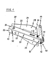
- FIG 1
- illustrates a perspective view of a door hinge device for an oven cavity of a cooking oven according to a preferred embodiment of the present invention, and
- FIG 2
- illustrates a perspective view of the door hinge device attached at a side panel of the oven cavity according to the preferred embodiment of the present invention.
-
FIG 1 illustrates a perspective view of a door hinge device for anoven cavity 36 of a cooking oven according to a preferred embodiment of the present invention. The door hinge device comprises adoor hinge 10 and aholder 18. InFIG 1 a part of thedoor hinge 10 is inserted in theholder 18. - The
door hinge 10 includes anoven lever 12 and adoor lever 14. Theoven lever 12 and thedoor lever 14 are interconnected by ahinge element 16. Thedoor lever 14 is provided for being fastened at and/or in an oven door. Theoven lever 12 is inserted in a guidingassembly 20 of theholder 18. Theoven lever 12 is insertable along its longitudinal direction into the guidingassembly 20. - The guiding
assembly 20 of theholder 18 is substantially a channel with a U-shaped cross-section. Theoven lever 14 comprises a rectangular cross-section, which is marginally smaller than the cross-section of the guidingassembly 20. - The
holder 18 is made of sheet and comprises fourparallel folding edges 22. Thus, theholder 18 comprises fivesheet sections outer sheet sections 24 are in the same plane and provided for lying against aside panel 38 at a sidewall of theoven cavity 36. Threeinner sheet sections 26 form theU-shaped guiding assembly 20. In particular, the sheet is made of metal. - The
outer sheet sections 24 are folded outwardly from the guidingassembly 20. When theouter sheet sections 24 lie against theside panel 38, then the guidingassembly 20 has a rectangular cross-section being marginally bigger than the cross-section of theoven lever 12. - In a rear portion of the guiding
assembly 20 there is aspring 28 in the upperinner sheet section 26. Thespring 28 is formed by a U-shaped cut-out. Thespring 28 is provided for clamping theoven lever 12 of thedoor hinge 10. - In a central
inner sheet section 26 of the guidingassembly 20 there is afixation flange 30. Thefixation flange 30 is also in the rear portion of the guidingassembly 20. Thefixation flange 30 keeps theoven lever 12 in its position. Thefixation flange 30 acts perpendicularly to the longitudinal axis of theoven lever 12. - The
oven lever 12 of thedoor hinge 10 is fixed at theholder 18 by ascrew 32. After theoven lever 12 has been inserted into the guidingassembly 20 of theholder 18, the only step for fastening thedoor hinge 10 is the tightening of thescrew 32. - The
holder 18 comprisesbores 34 in theouter sheet sections 24. By saidbores 34 and suitable fixing elements, like screws, theholder 18 can be fastened at theside panel 38 of the oven cavity. -
FIG 2 illustrates a perspective view of the door hinge device attached at theside panel 38 of theoven cavity 36 according to the preferred embodiment of the present invention. - The
holder 18 is attached at theside panel 38 of theoven cavity 36, wherein theouter sheet sections 24 of theholder 18 lie against saidside panel 38. In this example, there are screw joints between theouter sheet sections 24 and theside panel 38. Theoven cavity 36 comprises afront frame 40. The guidingassembly 20 and theoven lever 12 penetrate thefront frame 40 through a cut-out 42 in a lower corner of saidfront frame 40. - The
door hinge 10 and 10' is shown twice inFIG 2 . A representation on the left hand side shows thedoor hinge 10, wherein theoven lever 12 has been inserted into the guidingassembly 20. Another representation on the right hand side shows the door hinge 10' before being inserted into the guidingassembly 20. The inserting direction is represented by anarrow 44. - The door hinge device according to the present invention allows a quick installation of an oven door in front of the
oven cavity 10. Typically, the oven door comprises two door hinges 10. As a first step the oven levers 12 has to be inserted into thecorresponding guiding assemblies 20. As a second step thescrews 32 has to be tightened in order to fix the oven levers 12 in the guidingassemblies 20 and at theholder 18. - Although an illustrative embodiment of the present invention has been described herein with reference to the accompanying drawings, it is to be understood that the present invention is not limited to that precise embodiment, and that various other changes and modifications may be affected therein by one skilled in the art without departing from the scope or spirit of the invention. All such changes and modifications are intended to be included within the scope of the invention as defined by the appended claims.
-
- 10
- door hinge
- 10'
- door hinge
- 12
- oven lever
- 14
- door lever
- 16
- hinge element
- 18
- holder
- 20
- guiding assembly
- 22
- folding edge
- 24
- outer sheet section
- 26
- inner sheet section
- 28
- spring
- 30
- fixation flange
- 32
- screw
- 34
- bore
- 36
- oven cavity
- 38
- side panel
- 40
- front frame
- 42
- cut-out
- 44
- inserting direction
Claims (14)
- A door hinge device for an oven cavity (36) of a cooking oven, wherein:- the door hinge device comprises a door hinge (10),- the door hinge (10) includes an oven lever (12) and a door lever (14),- the door lever (14) is pivoting at and connected to the oven lever (12) by a hinge element (16), and- the door lever (14) is attached or attachable at and/or in an oven door,characterized in, that
the door hinge device comprises a holder (18) attached or attachable at a side panel (38) of the oven cavity (36), and the oven lever (12) of the door hinge (10) is removably inserted in or removably insertable into a guiding assembly (20) of the holder (18). - The door hinge device according to claim 1, characterized in, that
the holder (18) is made of a sheet by folding. - The door hinge device according to claim 1 or 2, characterized in, that
the guiding assembly (20) of the holder (18) has a U-shaped cross-section. - The door hinge device according to any one of the preceding claims,
characterized in, that
the guiding assembly (20) comprises at least one screw (32) for fixing the oven lever (12). - The door hinge device according to claim 4, characterized in, that
the screw (32) is arranged in a front portion of the guiding assembly (20). - The door hinge device according to any one of the preceding claims,
characterized in, that
the guiding assembly (20) comprises at least one spring (28) for clamping the oven lever (12). - The door hinge device according to claim 6, characterized in, that
the spring (28) is arranged in a rear portion of the guiding assembly (20). - The door hinge device according to claim 6 or 7, characterized in, that
the spring (28) is formed as a U-shaped cut-out. - The door hinge device according to any one of the preceding claims,
characterized in, that
the guiding assembly (20) comprises at least one fixation flange (30) for keeping the oven lever (12) in its position. - The door hinge device according to claim 9, characterized in, that
the fixation flange (30) acts perpendicular to the longitudinal axis of the oven lever (12). - The door hinge device according to claim 9 or 10, characterized in, that
the fixation flange (30) is arranged in a rear portion of the guiding assembly (20). - A cooking oven with at least one oven cavity (36) and at least one oven door for closing said oven cavity (36), characterized in, that
the cooking oven comprises at least one door hinge device according to any one of the claims 1 to 11. - The cooking oven according to claim 12,
characterized in, that
the oven cavity (36) comprises a front frame (40) with at least one cut-out (42), wherein the at least one guiding device (20) and/or the at least one oven lever (12) penetrates through said cut-out (42). - The cooking oven according to claim 12 or 13, characterized in, that
the cooking oven comprises a pair of door hinge devices arranged at the two side panels (38) of the oven cavity (36).
Priority Applications (1)
| Application Number | Priority Date | Filing Date | Title |
|---|---|---|---|
| EP20100003523 EP2372059B1 (en) | 2010-03-31 | 2010-03-31 | A door hinge device for an oven cavity of a cooking oven |
Applications Claiming Priority (1)
| Application Number | Priority Date | Filing Date | Title |
|---|---|---|---|
| EP20100003523 EP2372059B1 (en) | 2010-03-31 | 2010-03-31 | A door hinge device for an oven cavity of a cooking oven |
Publications (2)
| Publication Number | Publication Date |
|---|---|
| EP2372059A1 true EP2372059A1 (en) | 2011-10-05 |
| EP2372059B1 EP2372059B1 (en) | 2014-01-29 |
Family
ID=42358216
Family Applications (1)
| Application Number | Title | Priority Date | Filing Date |
|---|---|---|---|
| EP20100003523 Not-in-force EP2372059B1 (en) | 2010-03-31 | 2010-03-31 | A door hinge device for an oven cavity of a cooking oven |
Country Status (1)
| Country | Link |
|---|---|
| EP (1) | EP2372059B1 (en) |
Cited By (1)
| Publication number | Priority date | Publication date | Assignee | Title |
|---|---|---|---|---|
| CN113513225A (en) * | 2020-04-09 | 2021-10-19 | 合肥华凌股份有限公司 | Hinge assembly, cabinet body equipment and refrigerator |
Citations (2)
| Publication number | Priority date | Publication date | Assignee | Title |
|---|---|---|---|---|
| US3327701A (en) * | 1966-06-13 | 1967-06-27 | Moffats Ltd | Hinge mechanism |
| EP1703053A2 (en) * | 2005-01-20 | 2006-09-20 | Electrolux Home Products Corporation N.V. | Hinge for a home appliance |
-
2010
- 2010-03-31 EP EP20100003523 patent/EP2372059B1/en not_active Not-in-force
Patent Citations (2)
| Publication number | Priority date | Publication date | Assignee | Title |
|---|---|---|---|---|
| US3327701A (en) * | 1966-06-13 | 1967-06-27 | Moffats Ltd | Hinge mechanism |
| EP1703053A2 (en) * | 2005-01-20 | 2006-09-20 | Electrolux Home Products Corporation N.V. | Hinge for a home appliance |
Cited By (1)
| Publication number | Priority date | Publication date | Assignee | Title |
|---|---|---|---|---|
| CN113513225A (en) * | 2020-04-09 | 2021-10-19 | 合肥华凌股份有限公司 | Hinge assembly, cabinet body equipment and refrigerator |
Also Published As
| Publication number | Publication date |
|---|---|
| EP2372059B1 (en) | 2014-01-29 |
Similar Documents
| Publication | Publication Date | Title |
|---|---|---|
| EP2774519B1 (en) | Shower door assembly | |
| US10277014B2 (en) | Profiled frame of a frame structure for an electrical enclosure or a distribution cabinet | |
| US8887355B2 (en) | Fastening assembly for built-in refrigerator on a side wall of a furniture body | |
| US20080035810A1 (en) | Offset brackets for expanding electronic equipment cabinets | |
| US20120063099A1 (en) | Rail seal for electronic equipment enclosure | |
| US7900954B2 (en) | Latching device for fixing an airbag | |
| EP2731404A1 (en) | An oven door for a microwave oven or a multifunctional oven with microwave heating function | |
| US6209263B1 (en) | Hurricane shutter system | |
| EP1389661A2 (en) | HInge | |
| US7581768B2 (en) | Anti-effraction safety system for door and window frames | |
| US20160326787A1 (en) | System and methods for securing a hinge to a frame | |
| EP2372059B1 (en) | A door hinge device for an oven cavity of a cooking oven | |
| US7516581B2 (en) | Split door frame assembly | |
| US8910346B1 (en) | Device for repairing hinge area of a door | |
| JP2008196115A (en) | Mounting device of entrance unit | |
| CN110234894B (en) | Fastening element | |
| US20200391807A1 (en) | Adjustable datum pin assembly for temporarily securing a vehicle component to a vehicle structure | |
| WO2010006434A1 (en) | Security camera assembly | |
| EP2580987B1 (en) | A drawer including a drawer panel and a drawer box | |
| EP2602554B1 (en) | Door for a domestic appliance, domestic appliance with a door and method for mounting a door profile | |
| JP2011187834A (en) | Fan fixture for cabinet | |
| EP2341292A1 (en) | An oven door with a plastic door column and a method for assembling said plastic door column | |
| JP4981645B2 (en) | Double-sided digger | |
| EP2390584B1 (en) | Oven cabinet | |
| CN103687742B (en) | Simply hinged fuel tank door closure and be assembled into the method on vehicle |
Legal Events
| Date | Code | Title | Description |
|---|---|---|---|
| PUAI | Public reference made under article 153(3) epc to a published international application that has entered the european phase |
Free format text: ORIGINAL CODE: 0009012 |
|
| AK | Designated contracting states |
Kind code of ref document: A1 Designated state(s): AT BE BG CH CY CZ DE DK EE ES FI FR GB GR HR HU IE IS IT LI LT LU LV MC MK MT NL NO PL PT RO SE SI SK SM TR |
|
| AX | Request for extension of the european patent |
Extension state: AL BA ME RS |
|
| 17P | Request for examination filed |
Effective date: 20120404 |
|
| 17Q | First examination report despatched |
Effective date: 20120928 |
|
| GRAP | Despatch of communication of intention to grant a patent |
Free format text: ORIGINAL CODE: EPIDOSNIGR1 |
|
| INTG | Intention to grant announced |
Effective date: 20130813 |
|
| GRAS | Grant fee paid |
Free format text: ORIGINAL CODE: EPIDOSNIGR3 |
|
| GRAA | (expected) grant |
Free format text: ORIGINAL CODE: 0009210 |
|
| AK | Designated contracting states |
Kind code of ref document: B1 Designated state(s): AT BE BG CH CY CZ DE DK EE ES FI FR GB GR HR HU IE IS IT LI LT LU LV MC MK MT NL NO PL PT RO SE SI SK SM TR |
|
| REG | Reference to a national code |
Ref country code: GB Ref legal event code: FG4D |
|
| REG | Reference to a national code |
Ref country code: CH Ref legal event code: EP |
|
| REG | Reference to a national code |
Ref country code: AT Ref legal event code: REF Ref document number: 651570 Country of ref document: AT Kind code of ref document: T Effective date: 20140215 |
|
| REG | Reference to a national code |
Ref country code: IE Ref legal event code: FG4D |
|
| REG | Reference to a national code |
Ref country code: DE Ref legal event code: R096 Ref document number: 602010013387 Country of ref document: DE Effective date: 20140313 |
|
| REG | Reference to a national code |
Ref country code: AT Ref legal event code: MK05 Ref document number: 651570 Country of ref document: AT Kind code of ref document: T Effective date: 20140129 |
|
| REG | Reference to a national code |
Ref country code: NL Ref legal event code: VDEP Effective date: 20140129 |
|
| REG | Reference to a national code |
Ref country code: LT Ref legal event code: MG4D |
|
| PG25 | Lapsed in a contracting state [announced via postgrant information from national office to epo] |
Ref country code: IS Free format text: LAPSE BECAUSE OF FAILURE TO SUBMIT A TRANSLATION OF THE DESCRIPTION OR TO PAY THE FEE WITHIN THE PRESCRIBED TIME-LIMIT Effective date: 20140529 Ref country code: NO Free format text: LAPSE BECAUSE OF FAILURE TO SUBMIT A TRANSLATION OF THE DESCRIPTION OR TO PAY THE FEE WITHIN THE PRESCRIBED TIME-LIMIT Effective date: 20140429 Ref country code: LT Free format text: LAPSE BECAUSE OF FAILURE TO SUBMIT A TRANSLATION OF THE DESCRIPTION OR TO PAY THE FEE WITHIN THE PRESCRIBED TIME-LIMIT Effective date: 20140129 |
|
| PG25 | Lapsed in a contracting state [announced via postgrant information from national office to epo] |
Ref country code: ES Free format text: LAPSE BECAUSE OF FAILURE TO SUBMIT A TRANSLATION OF THE DESCRIPTION OR TO PAY THE FEE WITHIN THE PRESCRIBED TIME-LIMIT Effective date: 20140129 Ref country code: SE Free format text: LAPSE BECAUSE OF FAILURE TO SUBMIT A TRANSLATION OF THE DESCRIPTION OR TO PAY THE FEE WITHIN THE PRESCRIBED TIME-LIMIT Effective date: 20140129 Ref country code: FI Free format text: LAPSE BECAUSE OF FAILURE TO SUBMIT A TRANSLATION OF THE DESCRIPTION OR TO PAY THE FEE WITHIN THE PRESCRIBED TIME-LIMIT Effective date: 20140129 Ref country code: AT Free format text: LAPSE BECAUSE OF FAILURE TO SUBMIT A TRANSLATION OF THE DESCRIPTION OR TO PAY THE FEE WITHIN THE PRESCRIBED TIME-LIMIT Effective date: 20140129 Ref country code: NL Free format text: LAPSE BECAUSE OF FAILURE TO SUBMIT A TRANSLATION OF THE DESCRIPTION OR TO PAY THE FEE WITHIN THE PRESCRIBED TIME-LIMIT Effective date: 20140129 Ref country code: PT Free format text: LAPSE BECAUSE OF FAILURE TO SUBMIT A TRANSLATION OF THE DESCRIPTION OR TO PAY THE FEE WITHIN THE PRESCRIBED TIME-LIMIT Effective date: 20140529 Ref country code: CY Free format text: LAPSE BECAUSE OF FAILURE TO SUBMIT A TRANSLATION OF THE DESCRIPTION OR TO PAY THE FEE WITHIN THE PRESCRIBED TIME-LIMIT Effective date: 20140129 |
|
| PG25 | Lapsed in a contracting state [announced via postgrant information from national office to epo] |
Ref country code: HR Free format text: LAPSE BECAUSE OF FAILURE TO SUBMIT A TRANSLATION OF THE DESCRIPTION OR TO PAY THE FEE WITHIN THE PRESCRIBED TIME-LIMIT Effective date: 20140129 Ref country code: BE Free format text: LAPSE BECAUSE OF FAILURE TO SUBMIT A TRANSLATION OF THE DESCRIPTION OR TO PAY THE FEE WITHIN THE PRESCRIBED TIME-LIMIT Effective date: 20140129 Ref country code: LV Free format text: LAPSE BECAUSE OF FAILURE TO SUBMIT A TRANSLATION OF THE DESCRIPTION OR TO PAY THE FEE WITHIN THE PRESCRIBED TIME-LIMIT Effective date: 20140129 |
|
| REG | Reference to a national code |
Ref country code: DE Ref legal event code: R097 Ref document number: 602010013387 Country of ref document: DE |
|
| PG25 | Lapsed in a contracting state [announced via postgrant information from national office to epo] |
Ref country code: LU Free format text: LAPSE BECAUSE OF FAILURE TO SUBMIT A TRANSLATION OF THE DESCRIPTION OR TO PAY THE FEE WITHIN THE PRESCRIBED TIME-LIMIT Effective date: 20140331 Ref country code: CZ Free format text: LAPSE BECAUSE OF FAILURE TO SUBMIT A TRANSLATION OF THE DESCRIPTION OR TO PAY THE FEE WITHIN THE PRESCRIBED TIME-LIMIT Effective date: 20140129 Ref country code: DK Free format text: LAPSE BECAUSE OF FAILURE TO SUBMIT A TRANSLATION OF THE DESCRIPTION OR TO PAY THE FEE WITHIN THE PRESCRIBED TIME-LIMIT Effective date: 20140129 Ref country code: EE Free format text: LAPSE BECAUSE OF FAILURE TO SUBMIT A TRANSLATION OF THE DESCRIPTION OR TO PAY THE FEE WITHIN THE PRESCRIBED TIME-LIMIT Effective date: 20140129 Ref country code: RO Free format text: LAPSE BECAUSE OF FAILURE TO SUBMIT A TRANSLATION OF THE DESCRIPTION OR TO PAY THE FEE WITHIN THE PRESCRIBED TIME-LIMIT Effective date: 20140129 |
|
| REG | Reference to a national code |
Ref country code: CH Ref legal event code: PL |
|
| PG25 | Lapsed in a contracting state [announced via postgrant information from national office to epo] |
Ref country code: SK Free format text: LAPSE BECAUSE OF FAILURE TO SUBMIT A TRANSLATION OF THE DESCRIPTION OR TO PAY THE FEE WITHIN THE PRESCRIBED TIME-LIMIT Effective date: 20140129 Ref country code: PL Free format text: LAPSE BECAUSE OF FAILURE TO SUBMIT A TRANSLATION OF THE DESCRIPTION OR TO PAY THE FEE WITHIN THE PRESCRIBED TIME-LIMIT Effective date: 20140129 |
|
| PLBE | No opposition filed within time limit |
Free format text: ORIGINAL CODE: 0009261 |
|
| STAA | Information on the status of an ep patent application or granted ep patent |
Free format text: STATUS: NO OPPOSITION FILED WITHIN TIME LIMIT |
|
| REG | Reference to a national code |
Ref country code: IE Ref legal event code: MM4A |
|
| 26N | No opposition filed |
Effective date: 20141030 |
|
| PG25 | Lapsed in a contracting state [announced via postgrant information from national office to epo] |
Ref country code: CH Free format text: LAPSE BECAUSE OF NON-PAYMENT OF DUE FEES Effective date: 20140331 Ref country code: IE Free format text: LAPSE BECAUSE OF NON-PAYMENT OF DUE FEES Effective date: 20140331 Ref country code: LI Free format text: LAPSE BECAUSE OF NON-PAYMENT OF DUE FEES Effective date: 20140331 |
|
| REG | Reference to a national code |
Ref country code: DE Ref legal event code: R097 Ref document number: 602010013387 Country of ref document: DE Effective date: 20141030 |
|
| PG25 | Lapsed in a contracting state [announced via postgrant information from national office to epo] |
Ref country code: SI Free format text: LAPSE BECAUSE OF FAILURE TO SUBMIT A TRANSLATION OF THE DESCRIPTION OR TO PAY THE FEE WITHIN THE PRESCRIBED TIME-LIMIT Effective date: 20140129 |
|
| PG25 | Lapsed in a contracting state [announced via postgrant information from national office to epo] |
Ref country code: MT Free format text: LAPSE BECAUSE OF FAILURE TO SUBMIT A TRANSLATION OF THE DESCRIPTION OR TO PAY THE FEE WITHIN THE PRESCRIBED TIME-LIMIT Effective date: 20140129 |
|
| REG | Reference to a national code |
Ref country code: FR Ref legal event code: PLFP Year of fee payment: 7 |
|
| PG25 | Lapsed in a contracting state [announced via postgrant information from national office to epo] |
Ref country code: SM Free format text: LAPSE BECAUSE OF FAILURE TO SUBMIT A TRANSLATION OF THE DESCRIPTION OR TO PAY THE FEE WITHIN THE PRESCRIBED TIME-LIMIT Effective date: 20140129 |
|
| PG25 | Lapsed in a contracting state [announced via postgrant information from national office to epo] |
Ref country code: MC Free format text: LAPSE BECAUSE OF FAILURE TO SUBMIT A TRANSLATION OF THE DESCRIPTION OR TO PAY THE FEE WITHIN THE PRESCRIBED TIME-LIMIT Effective date: 20140129 |
|
| PG25 | Lapsed in a contracting state [announced via postgrant information from national office to epo] |
Ref country code: GR Free format text: LAPSE BECAUSE OF FAILURE TO SUBMIT A TRANSLATION OF THE DESCRIPTION OR TO PAY THE FEE WITHIN THE PRESCRIBED TIME-LIMIT Effective date: 20140430 Ref country code: BG Free format text: LAPSE BECAUSE OF FAILURE TO SUBMIT A TRANSLATION OF THE DESCRIPTION OR TO PAY THE FEE WITHIN THE PRESCRIBED TIME-LIMIT Effective date: 20140129 |
|
| PG25 | Lapsed in a contracting state [announced via postgrant information from national office to epo] |
Ref country code: TR Free format text: LAPSE BECAUSE OF FAILURE TO SUBMIT A TRANSLATION OF THE DESCRIPTION OR TO PAY THE FEE WITHIN THE PRESCRIBED TIME-LIMIT Effective date: 20140129 Ref country code: HU Free format text: LAPSE BECAUSE OF FAILURE TO SUBMIT A TRANSLATION OF THE DESCRIPTION OR TO PAY THE FEE WITHIN THE PRESCRIBED TIME-LIMIT; INVALID AB INITIO Effective date: 20100331 |
|
| REG | Reference to a national code |
Ref country code: FR Ref legal event code: PLFP Year of fee payment: 8 |
|
| PGFP | Annual fee paid to national office [announced via postgrant information from national office to epo] |
Ref country code: DE Payment date: 20170322 Year of fee payment: 8 |
|
| REG | Reference to a national code |
Ref country code: FR Ref legal event code: PLFP Year of fee payment: 9 |
|
| PG25 | Lapsed in a contracting state [announced via postgrant information from national office to epo] |
Ref country code: MK Free format text: LAPSE BECAUSE OF FAILURE TO SUBMIT A TRANSLATION OF THE DESCRIPTION OR TO PAY THE FEE WITHIN THE PRESCRIBED TIME-LIMIT Effective date: 20140129 |
|
| REG | Reference to a national code |
Ref country code: DE Ref legal event code: R119 Ref document number: 602010013387 Country of ref document: DE |
|
| PG25 | Lapsed in a contracting state [announced via postgrant information from national office to epo] |
Ref country code: DE Free format text: LAPSE BECAUSE OF NON-PAYMENT OF DUE FEES Effective date: 20181002 |
|
| PGFP | Annual fee paid to national office [announced via postgrant information from national office to epo] |
Ref country code: GB Payment date: 20200323 Year of fee payment: 11 |
|
| PGFP | Annual fee paid to national office [announced via postgrant information from national office to epo] |
Ref country code: FR Payment date: 20200320 Year of fee payment: 11 |
|
| PGFP | Annual fee paid to national office [announced via postgrant information from national office to epo] |
Ref country code: IT Payment date: 20200318 Year of fee payment: 11 |
|
| GBPC | Gb: european patent ceased through non-payment of renewal fee |
Effective date: 20210331 |
|
| PG25 | Lapsed in a contracting state [announced via postgrant information from national office to epo] |
Ref country code: FR Free format text: LAPSE BECAUSE OF NON-PAYMENT OF DUE FEES Effective date: 20210331 Ref country code: GB Free format text: LAPSE BECAUSE OF NON-PAYMENT OF DUE FEES Effective date: 20210331 |
|
| PG25 | Lapsed in a contracting state [announced via postgrant information from national office to epo] |
Ref country code: IT Free format text: LAPSE BECAUSE OF NON-PAYMENT OF DUE FEES Effective date: 20210331 |