EP2372028A1 - Closing device for manholes - Google Patents
Closing device for manholes Download PDFInfo
- Publication number
- EP2372028A1 EP2372028A1 EP11002561A EP11002561A EP2372028A1 EP 2372028 A1 EP2372028 A1 EP 2372028A1 EP 11002561 A EP11002561 A EP 11002561A EP 11002561 A EP11002561 A EP 11002561A EP 2372028 A1 EP2372028 A1 EP 2372028A1
- Authority
- EP
- European Patent Office
- Prior art keywords
- cover
- frame
- edge
- closing device
- thrusting
- Prior art date
- Legal status (The legal status is an assumption and is not a legal conclusion. Google has not performed a legal analysis and makes no representation as to the accuracy of the status listed.)
- Granted
Links
Images


Classifications
-
- E—FIXED CONSTRUCTIONS
- E02—HYDRAULIC ENGINEERING; FOUNDATIONS; SOIL SHIFTING
- E02D—FOUNDATIONS; EXCAVATIONS; EMBANKMENTS; UNDERGROUND OR UNDERWATER STRUCTURES
- E02D29/00—Independent underground or underwater structures; Retaining walls
- E02D29/12—Manhole shafts; Other inspection or access chambers; Accessories therefor
- E02D29/14—Covers for manholes or the like; Frames for covers
- E02D29/1427—Locking devices
Definitions
- the present invention concerns a closing device for manholes/traps.
- Roads are characterized by the presence of various types of manholes/traps, for example city water system manholes, rainwater traps, sewer system inspection manholes or electric and telephone line manholes.
- Said manholes/traps have a closing device at the top, which is usually square, rectangular or round in shape, and is constituted by a frame that is well anchored to the manhole and by a cover associated with and resting on the frame.
- the cover is therefore removably associated with the frame and when necessary it can be removed in order to inspect the inside of the manhole.
- the cover is provided with means that are suited to make it easier to lift it, for example using adequate tools like a lever or a spanner, so that the cover can be grasped and completely removed from the frame.
- one or more hinges are interposed between the frame and the cover, and the latter is opened with a rotational movement around said hinges.
- the closing devices are usually positioned along roadways and for this reason they are subjected to continuous and high stress due to the passage of motor vehicles, even heavy ones like trucks, buses, etc.
- closing devices are made using materials with special mechanical characteristics in order to ensure high rigidity and high resistance to wear.
- a commonly used material is cast iron, laminar or preferably spheroidal graphite cast iron.
- a drawback posed by said closing device is due to the above mentioned continuous stress to which they are subjected, and in particular to the impacts of the cover against the frame caused by the passage of motor vehicles. Over time, said impacts cause the wear of the parts in contact with each other, or even the breakage of the cover or the frame.
- a first known solution to this problem is represented by the interposition of a rubber gasket, normally in neoprene, between the frame and the cover that, when the motor vehicles run over the cover, absorbs the shocks and avoids direct contact between the parts and consequently prevents them from wearing out or breaking.
- a rubber gasket normally in neoprene
- a first drawback is represented by the fact that the gasket wears out over time, as it is subjected, too, to continuous stress and pressure exerted by the cover.
- the delayed replacement of the gasket may furthermore damage the closing device itself, as the gasket does not serve its useful function and the cover can move and hit against the frame until causing the breakage of the cover, frame, or hinges, if provided.
- the main object of the present invention is therefore to solve the problems that characterize the known solutions.
- the present invention is based on the general consideration that it is advisable to provide closing devices in which the cover and the frame are thrust against each other reducing the clearance between them as much as possible.
- the object of the present invention is a closing device according to claim 1, that is, a closing device for manholes/traps and the like, comprising a frame and a cover associated therewith and comprising means for exerting a mutual thrusting action between said cover and said frame.
- a closing device for manholes/traps and the like comprising a frame and a cover associated therewith and comprising means for exerting a mutual thrusting action between said cover and said frame.
- the thrusting means preferably operate in two directions between the cover and the frame.
- the thrusting means are preferably associated with the cover and comprise at least one elastically yielding element in the shape of an elastic tab, which is produced together with the cover in a single piece.
- the closing device does not need any additional elements, like gaskets, and the closing and opening operations are simplified.
- the thrusting means are arranged in three separate areas between the cover and the frame, in order to define a thrusting plane of the cover towards the frame.
- the three thrust areas guarantee a stable and firm support for the cover when it rests on the frame.
- the cover and the frame preferably have a parallelogram shape and the three areas belong to two opposite sides of the parallelogram.
- a portion of the cover is preferably in direct contact with a corresponding portion of the frame.
- the device preferably comprises aid means suited to house special tools, for example levers or spanners, used to move the cover.
- a first embodiment of the closing device 1 according to the present invention is described here below with reference to Figures from 1 to 21.
- the closing device 1 is shown while used to close an opening O delimited by an edge B (as shown for example in Figures from 13 to 17).
- Said edge B can represent the upper portion of a concrete street manhole and the opening O the area to be inspected. It is evident, however, that the edge B may be constituted by the road surface or in general by a ground area where there is an opening O to be inspected.
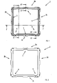
- the closing device 1 comprises a frame 2 and a cover 3.
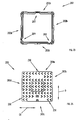
- the frame 2 and the cover 3 have a matching and substantially square shape.
- Variant embodiments of the invention may have different shapes, known especially in the applications for street manholes, for example rectangular or round.
- the frame 2 is anchored to the edge B in a fixed manner, according to techniques that are known in the sector.
- the frame 2 comprises four edges 2a, 2b, 2c and 2d, two of which, 2b and 2d, are specular and identical to each other.
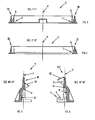
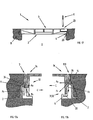
- the cross section of the edges 2a-2d is substantially in the shape of an upturned T, as shown in the sectional views of Figures 3 and 4 .
- this cross section features, in a direction towards the centre of the frame 2, a raised portion 5 defining a substantially U-shaped area 6 suited to accommodate the cover 3, as is better illustrated below.
- the first edge 2a is not provided with said raised portion, as shown in Figure 4 .
- the profile of the edges is shaped at the level of three areas 7, 8 and 9 of the frame 2.
- a first shaped area 7 is defined at the centre of the first edge 2a and, as can be observed in the detail shown in cross section in Figure 5 , is provided with a first upper surface 10 that is substantially vertical and substantially parallel to a vertical reference axis V that intersects at right angles the plane defined by the frame 2, a second substantially rectilinear and inclined surface 11 and a third lower vertical surface 12.
- the inclination angle Al of the second surface with respect to the axis V is 60°.
- the vertical axis V that must be understood as a reference axis that intersects at right angles the plane defined by the frame 2 with reference to the frame 2, or as a reference axis that intersects at right angles the plane defined by the cover 3 with reference to the cover 3.
- the second and third shaped areas 8 and 9, equal to each other, are defined in the edge 2c facing the edge 2a where there is said first shaped area 7 and are located in proximity to the side ends of the edge 2c.
- Said shaped areas 8, 9 are substantially equal to the first shaped area 7 and each of them, as shown in Figure 6 , is provided with a first upper surface 13 that is substantially vertical and substantially parallel to the axis V, a second substantially rectilinear and inclined surface 14 and a third lower vertical surface 15.
- the inclination angle A2 of the second surface 14 with respect to the axis V is 45°.
- the cover 3 is shown with reference to Figures from 7 to 12.
- the cover 3 comprises four edges 3a, 3b, 3c and 3d, two of which, 3b and 3d, are specular and identical to each other.
- the four edges 3a-3d are defined by a side surface 20 that is substantially vertical and substantially parallel to the axis V, which substantially defines the cover 3, as shown in Figure 8 and in the sectional view of Figure 9 .
- the cover 3 is provided with further internal vertical walls 21 forming ribs that give the cover 3 a higher structural rigidity.
- Said ribs 21 are present in the lower part of the cover 3, to be understood as the part that faces the opening O when the cover 3 is installed on the frame 2.
- the upper part of the cover 3 is provided with a plurality of projections 22, whose height is in the order of a few millimetres, with suitable shape and orientation, thanks to which the cover 3 shows the desired characteristics in terms of grip and noise when the wheels of motor vehicles pass over it.
- a first tab 30 is defined at the centre of the first edge 3a between two open areas 30a and 30b created in the edge 3a, as shown in Figure 11a in the view of the first area 27 of the edge 3a.
- the first tab 30 is provided with a first upper surface 33 that is substantially vertical and substantially parallel to the axis V and a second surface 34 that is substantially rectilinear and inclined and extends towards the outside with respect to the first upper surface 33.
- the inclination angle B1 of the second surface 34 with respect to the axis V is 120°.
- Two tabs 31, 32 are defined in the edge 3c facing the edge 3a where there is said first tab 30 and are located in proximity to the side ends of the edge 3c.
- Each one of said tabs 31, 32 is defined between two open areas 31a, 32a and 31b, 32b created in the edge 3c, as shown in Figure 12a in the view of the areas 28, 29 of the edge 3c.
- Each tab 31, 32 is provided with a first upper surface 35 that is substantially vertical and substantially parallel to the axis V, a substantially rectilinear and inclined second surface 36 that extends towards the outside with respect to the first upper surface 35 and connected to it through a rectilinear section 37, a substantially rectilinear and inclined third surface 38 and a fourth lower surface 39 that is substantially vertical and substantially parallel to the axis V.
- the inclination angle B2 of the second surface 36 with respect to the axis V is equal to 135° and the inclination angle B3 of the third surface 38 with respect to the axis V is equal to 45°.
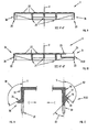
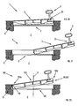
- Figures from 13 to 17 show the sequence of the closing steps of the device 1 of the invention, with the coupling of the cover 3 to the frame 2.
- the movements of the cover 3 are carried out by the operator by means of a key K to be introduced in the shaped hole 23 provided in the cover 3.
- the cover 3 is made slide on the frame 2 while resting it on the side perimeter surface 20 of the first edge 3a where the first tab 30 is provided.
- the cover 3 is then pushed until the first edge 3a comes into contact with the first edge 2a of the frame 2 and the first tab 30 comes into contact with the first shaped area 7 ( Figure 14 ). From this position, the cover 3 is lowered towards the frame 2 with a rotational movement ( Figure 15 ).
- the second and the third tab 31, 32 of the third edge 3c come into contact, with their third inclined surface 38, with the first upper surface 13 of the corresponding shaped area 8, 9 of the frame 2.
- the inclined surface 38 and the elasticity of the tab 31, 32 determine a movement of the tab 31, 32 towards the centre of the cover 3, as shown in Figure 16a , and its sliding movement along the first upper surface 13 of the shaped area 8, 9 as the cover 3 is lowered. This sliding step continues until the lower part of the side perimeter surface 20 of the third edge 3c of the cover 3 rests on the U-shaped area 6 suited to accommodate the third edge 3c of the frame 2 ( Figure 17 and Figure 17b ).
- the key K is then removed from the shaped hole 23 ( Figure 17 ).
- the second inclined surface 36 of the tab 31, 32 comes against the second inclined surface 14 of the shaped area 8, 9 of the frame 2.
- Analogously, as shown in Figure 17a in the opposite edge 3a the second inclined surface 34 of the first tab 30 rests against the second inclined surface 11 of the first shaped area 7 of the frame 2.
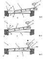
- the three tabs 30, 31 and 32 in said closed position of the cover 3, determine, thanks to their elasticity, a thrusting action of the cover 3 against the frame 2. More particularly, as shown in Figures 17a and 17b , the inclination of the contacting surfaces of the tab 30, 31, 32 on one side and of the shaped area 7, 8, 9 on the other side, determine a corresponding inclined thrusting force Fs.
- Said thrusting force Fs can be divided into a first vertical thrust component Fv along the direction V and a second horizontal thrust component Fo that substantially lies on the plane defined by the cover 3.
- the thrust component Fv acts on the cover 3 so as to maintain it in contact with the frame 2 in a stable manner, in particular the side perimeter surface 20 of the cover 3 is maintained firmly and directly resting on the U-shaped area 6 suited to accommodate the frame edges.
- the horizontal thrust component Fo acts on the cover 3 so as to keep it in contact with the frame 2 in a stable manner, in particular along the horizontal direction O between the two opposite edges 2a, 2c and 3a, 3c.
- the horizontal thrust component Fo acts on the cover 3 so as to keep it in contact with the frame 2 in a stable manner, in particular along the horizontal direction O between the two opposite edges 2a, 2c and 3a, 3c.
- said vertical direction O therefore, there is no clearance between the cover 3 and the frame 2, and when motor vehicles run over the cover 3 there are no mutual impacts in that direction O between the cover 3 and the frame 2. This further reduces the mutual wear of the parts and the risk of breaking them.
- the extent of the thrusting force Fs and its division into the two components Fv and Fo depends, on one side, on the elasticity characteristics of the materials used for making the tabs and, on the other side, on the inclination angles A1, A2, B1, B2 of the inclined surfaces in contact with the tabs 30, 31, 32 and the shaped areas 7, 8, 9.
- the three shaped areas 7, 8, 9 and the corresponding tabs 30, 31, 32 are advantageously arranged on the edges of the frame 2 and of the cover 3, so as to be arranged at the vertices of a hypothetical triangle and to define a thrusting plane of the cover 3 towards the frame 2.
- a different number of shaped areas and tabs can be provided, and they can be arranged along different areas of the respective edges.
- only the second and the third tab 31, 32 may be elastically yielding, while the first tab 30 may be substantially rigid and thus serve only as a resting surface.
- the first steps, Figures 18 and 19 include the insertion of the tip of a lever L in the opening 24 in the cover 3 and its rotation to lift the corresponding edge 3c of the cover 3 from the frame 2.
- the second and the third tabs 31, 32 are pushed towards the centre of the cover 3 thanks to their elasticity and thanks to the sliding movement of their inclined surfaces 36 on the inclined surfaces 14 of the shaped areas 8, 9 ( Figures 19 and 19a ).
- the cover 3 is partially lifted, as shown in Figure 20 , the key K is introduced in the shaped hole 23 in the cover 3 and therefore the cover 3 is slided completely out of the frame 2 ( Figure 21 ).
- Figure 22 shows a sectional view of a variant embodiment of the closing device 100 of the invention.
- Said variant embodiment differs from the embodiment described above in that the cover 103 cannot be completely removed from the frame 102 but is hinged to it with an edge 103a, that is, the edge opposite the edge 103c that is lifted in order to open the device 100.
- the cover 102 can be rotated around a hinge 110 and is provided, analogously to the embodiment described above, with one pair of elastic tabs 131, 132 on the opposite edge 103c.
- the elastic tabs 131, 132 produce the same thrusting action described above, the prevailing action of the vertical thrust component Fv of the cover 103 towards the frame 102 being in this case advantageous, as the hinge 110 is in itself an element that locks the cover 3 to the frame 102 in the horizontal direction O.
- a horizontal thrust component Fo makes it possible to recover any clearance of the hinge 110.
- Figures 23 and 24 schematically show the frame 202 and the cover 203 of a further variant embodiment of a closing device 200 according to the invention that differs from the first embodiment described above in that the three shaped areas 207, 208 and 209 and the corresponding three tabs 230, 231 and 232 are arranged on three separate edges 202a, 202c and 202d, 203a, 203c and 203d of the frame 202 and of the cover 203, respectively.
- the three shaped areas 207, 208 and 209 and the corresponding three tabs 230, 231 and 232 are advantageously arranged at the vertices of a hypothetical triangle to define a thrusting plane of the cover 203 towards the frame 202.
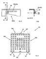
- Figures 25 and 26 show a possible variant embodiment of the tabs of the cover of the closing device that is the subject of the invention.
- each one of the tabs 331, 332 that are equal to each other or even equal and specular to each other, is defined by an open area 331a, 332a provided in the third edge 3c.
- Each tab 331, 332, as better illustrated in Figure 26 has a substantially rectilinear and inclined surface 336 that extends towards the outside, a substantially rectilinear and inclined surface 338 and a substantially vertical lower surface 339.
- the function of the inclined surfaces 336 and 338 of said variant embodiment corresponds to the function of the second surface 36 and of the third surface 38, respectively, of the first embodiment described above.
- the inclined surface 338 together with the elasticity of the tab 331, 332 obtained thanks to the presence of the open area 331a, 332a, makes it possible to couple the cover with the frame.
- the inclined surface 336 together with the elasticity of the tab 331, 332 obtained thanks to the presence of the open area 331a, 332a determines the inclined thrusting force Fs between the cover and the frame when they are coupled with each other and the device is closed. Furthermore, the inclined surface 336 and the elasticity of the tab 331, 332 facilitate the removal of the cover from the frame.
- Figure 27 shows a possible embodiment of a cover 303 according to the invention, in which at the level of the area 327 of the first edge 303a there is a tab 30 of the type described with reference to Figures 11 and 11a , while at the level of the areas 328 and 329 of the third edge 303c there are two corresponding tabs 331 and 332 of the type described with reference to Figures 25 and 26 .
- the elastic tabs can be provided on the frame instead of on the cover, and consequently the shaped areas will be on the cover instead of on the frame.
- some elastic tabs can be provided on the frame and some on the cover.
- the elastic tabs may be produced in the shape of inserts of a different material associated with the cover or with the frame, depending on whether the embodiment desired has the tab on the cover or on the frame.
- the present invention allows all the set objects to be achieved.
- the invention makes it possible to provide closing devices that are highly resistant to stress, last longer and need less maintenance than the devices of known type.
Landscapes
- Engineering & Computer Science (AREA)
- Environmental & Geological Engineering (AREA)
- Life Sciences & Earth Sciences (AREA)
- General Life Sciences & Earth Sciences (AREA)
- Mining & Mineral Resources (AREA)
- Paleontology (AREA)
- Civil Engineering (AREA)
- General Engineering & Computer Science (AREA)
- Structural Engineering (AREA)
- Underground Structures, Protecting, Testing And Restoring Foundations (AREA)
- Window Of Vehicle (AREA)
- Vehicle Step Arrangements And Article Storage (AREA)
- Load-Engaging Elements For Cranes (AREA)
Abstract
Description
- The present invention concerns a closing device for manholes/traps.
- In particular, it concerns a closing device for manholes/traps situated along roadways.
- Roads are characterized by the presence of various types of manholes/traps, for example city water system manholes, rainwater traps, sewer system inspection manholes or electric and telephone line manholes.
- Said manholes/traps have a closing device at the top, which is usually square, rectangular or round in shape, and is constituted by a frame that is well anchored to the manhole and by a cover associated with and resting on the frame.
- The cover is therefore removably associated with the frame and when necessary it can be removed in order to inspect the inside of the manhole.
- For this purpose, the cover is provided with means that are suited to make it easier to lift it, for example using adequate tools like a lever or a spanner, so that the cover can be grasped and completely removed from the frame.
- In other closing devices of known type, one or more hinges are interposed between the frame and the cover, and the latter is opened with a rotational movement around said hinges.
- The closing devices, as already explained, are usually positioned along roadways and for this reason they are subjected to continuous and high stress due to the passage of motor vehicles, even heavy ones like trucks, buses, etc.
- For this purpose, closing devices are made using materials with special mechanical characteristics in order to ensure high rigidity and high resistance to wear. A commonly used material is cast iron, laminar or preferably spheroidal graphite cast iron.
- A drawback posed by said closing device is due to the above mentioned continuous stress to which they are subjected, and in particular to the impacts of the cover against the frame caused by the passage of motor vehicles. Over time, said impacts cause the wear of the parts in contact with each other, or even the breakage of the cover or the frame.
- A first known solution to this problem is represented by the interposition of a rubber gasket, normally in neoprene, between the frame and the cover that, when the motor vehicles run over the cover, absorbs the shocks and avoids direct contact between the parts and consequently prevents them from wearing out or breaking.
- This solution, however, poses some drawbacks.
- A first drawback is represented by the fact that the gasket wears out over time, as it is subjected, too, to continuous stress and pressure exerted by the cover.
- This requires a periodical inspection and if necessary the replacement of the gasket, which also involves the related costs.
- The delayed replacement of the gasket may furthermore damage the closing device itself, as the gasket does not serve its useful function and the cover can move and hit against the frame until causing the breakage of the cover, frame, or hinges, if provided.
- The main object of the present invention is therefore to solve the problems that characterize the known solutions.
- In particular, it is one object of the present invention to provide a closing device that is more resistant to stress than the devices belonging to the known art.
- It is another object of the present invention to provide a closing device that lasts longer than the devices of known type.
- It is a further object of the present invention to provide a closing device that needs less maintenance than the devices of known type.
- It is another object of the present invention to provide a closing device that is simpler than the devices of known type.
- The present invention is based on the general consideration that it is advisable to provide closing devices in which the cover and the frame are thrust against each other reducing the clearance between them as much as possible.
- According to a first embodiment, the object of the present invention is a closing device according to
claim 1, that is, a closing device for manholes/traps and the like, comprising a frame and a cover associated therewith and comprising means for exerting a mutual thrusting action between said cover and said frame. Advantageously, when the cover is associated with the frame the clearance between the parts is reduced and therefore also the impacts of the cover against the frame are reduced when motor vehicles run over the manhole/trap. - Further embodiments of the present invention are described in detail in the dependent claims.
- The thrusting means preferably operate in two directions between the cover and the frame.
- Advantageously, between the cover and the frame there is no clearance, neither in the vertical nor in the horizontal direction.
- The thrusting means are preferably associated with the cover and comprise at least one elastically yielding element in the shape of an elastic tab, which is produced together with the cover in a single piece.
- Advantageously, the closing device does not need any additional elements, like gaskets, and the closing and opening operations are simplified.
- Even more preferably, the thrusting means are arranged in three separate areas between the cover and the frame, in order to define a thrusting plane of the cover towards the frame.
- Advantageously, the three thrust areas guarantee a stable and firm support for the cover when it rests on the frame.
- The cover and the frame preferably have a parallelogram shape and the three areas belong to two opposite sides of the parallelogram.
- A portion of the cover is preferably in direct contact with a corresponding portion of the frame.
- Advantageously, there is no clearance between the cover and the frame and there are no mutual impacts between the parts when motor vehicles run over the cover. Still advantageously, it is not necessary to add shock absorbing elements like gaskets between the cover and the frame.
- The device preferably comprises aid means suited to house special tools, for example levers or spanners, used to move the cover.
- Further objects, advantages and characteristics, as well as embodiments of the present invention are defined in the claims and will be illustrated below by means of the following description with reference to the attached drawings. In particular:
-
Figure 1 shows a plan view from above of the frame of a closing device according to a first embodiment of the present invention; -
Figure 2 shows a plan view from below of the frame shown inFigure 1 ; -
Figure 3 shows a sectional view according to plane I-I of the frame shown inFigure 1 ; -
Figure 4 shows a sectional view according to plane II-II of the frame shown inFigure 1 ; -
Figure 5 shows a sectional view according to plane III-III of the frame shown inFigure 1 ; -
Figure 6 shows a sectional view according to plane IV-IV of the frame shown inFigure 1 ; -
Figure 7 shows a plan view from above of the cover of a closing device according to the first embodiment of the present invention; -
Figure 8 shows a plan view from below of the cover shown inFigure 7 ; -
Figure 9 shows a sectional view according to plane V-V of the cover shown inFigure 7 ; -
Figure 10 shows a sectional view according to plane VI-VI of the frame shown inFigure 7 ; -
Figure 11 shows a sectional view of a detail of the cover shown inFigure 7 ; -
Figure 11 a shows a view of the detail shown inFigure 11 ; -
Figure 12 shows a sectional view of another detail of the cover shown inFigure 7 ; -
Figure 12a shows a view of the detail shown inFigure 12 ; - Figures from 13 to 17 show the closing steps of the device according to the first embodiment of the invention;
-
Figures 15a, 16a ,17a and 17b show sectional views of enlarged details during some operating steps illustrated in the correspondingFigures 15 ,16 and17 ; - Figures from 18 to 21 show the opening step of the device according to the first embodiment of the invention;
-
Figure 19a shows a sectional view of an enlarged detail of the operating step illustrated inFigure 19 ; -
Figure 22 shows a second embodiment of the closing device that is the subject of the invention; -
Figure 23 shows a plan view from above of the frame of a closing device according to a third embodiment of the present invention; -
Figure 24 shows a plan view from above of a cover that can be associated with the frame shown inFigure 25 ; -
Figure 25 shows a variant embodiment of the detail shown inFigure 12a ; -
Figure 26 shows a sectional view according to plane VII-VII of the detail shown inFigure 25 ; -
Figure 27 shows a plan view from above of a variant embodiment of the cover shown inFigure 7 . - Although the present invention is described below with reference to its embodiments illustrated in the drawings, the present invention is not limited to the embodiments described below and illustrated in the drawings. On the contrary, the embodiments described and illustrated herein clarify some aspects of the present invention, the scope of which is defined in the claims.
- A first embodiment of the
closing device 1 according to the present invention is described here below with reference to Figures from 1 to 21. - In the drawings, the
closing device 1 is shown while used to close an opening O delimited by an edge B (as shown for example in Figures from 13 to 17). Said edge B can represent the upper portion of a concrete street manhole and the opening O the area to be inspected. It is evident, however, that the edge B may be constituted by the road surface or in general by a ground area where there is an opening O to be inspected. - Furthermore, the
closing device 1 that is described here below is of the solid type, meaning that it is suited to cover the opening O completely and in a substantially tight manner. However, according to variant embodiments of the invention, the closing device can be partially open, for example it can be of the grid type suitable for collecting rainwater. - The
closing device 1 comprises aframe 2 and acover 3. - The
frame 2 and thecover 3 have a matching and substantially square shape. Variant embodiments of the invention may have different shapes, known especially in the applications for street manholes, for example rectangular or round. - The
frame 2 is anchored to the edge B in a fixed manner, according to techniques that are known in the sector. - The
frame 2 is shown with reference to Figures from 1 to 6. - The
frame 2 comprises fouredges - The cross section of the
edges 2a-2d is substantially in the shape of an upturned T, as shown in the sectional views ofFigures 3 and 4 . In three of the four edges, 2b, 2c and 2d, this cross section features, in a direction towards the centre of theframe 2, a raisedportion 5 defining a substantiallyU-shaped area 6 suited to accommodate thecover 3, as is better illustrated below. Thefirst edge 2a is not provided with said raised portion, as shown inFigure 4 . - The profile of the edges is shaped at the level of three
areas frame 2. - In particular, a first shaped
area 7 is defined at the centre of thefirst edge 2a and, as can be observed in the detail shown in cross section inFigure 5 , is provided with a firstupper surface 10 that is substantially vertical and substantially parallel to a vertical reference axis V that intersects at right angles the plane defined by theframe 2, a second substantially rectilinear andinclined surface 11 and a third lowervertical surface 12. The inclination angle Al of the second surface with respect to the axis V is 60°. - In the following part of the description, reference is often made to the vertical axis V that must be understood as a reference axis that intersects at right angles the plane defined by the
frame 2 with reference to theframe 2, or as a reference axis that intersects at right angles the plane defined by thecover 3 with reference to thecover 3. - The second and third
shaped areas edge 2c facing theedge 2a where there is said first shapedarea 7 and are located in proximity to the side ends of the edge 2c. Said shapedareas area 7 and each of them, as shown inFigure 6 , is provided with a firstupper surface 13 that is substantially vertical and substantially parallel to the axis V, a second substantially rectilinear andinclined surface 14 and a third lowervertical surface 15. The inclination angle A2 of thesecond surface 14 with respect to the axis V is 45°. - The
cover 3 is shown with reference to Figures from 7 to 12. - The
cover 3 comprises fouredges - The four
edges 3a-3d are defined by aside surface 20 that is substantially vertical and substantially parallel to the axis V, which substantially defines thecover 3, as shown inFigure 8 and in the sectional view ofFigure 9 . In addition to theside perimeter surface 20, thecover 3 is provided with further internalvertical walls 21 forming ribs that give thecover 3 a higher structural rigidity. Saidribs 21 are present in the lower part of thecover 3, to be understood as the part that faces the opening O when thecover 3 is installed on theframe 2. The upper part of thecover 3 is provided with a plurality ofprojections 22, whose height is in the order of a few millimetres, with suitable shape and orientation, thanks to which thecover 3 shows the desired characteristics in terms of grip and noise when the wheels of motor vehicles pass over it. - Always on the upper part of the
cover 3 there is a shapedhole 23 for the insertion of an opening key K, while in proximity to thethird edge 3c there is anopening 24 that occupies partially the side surface and partially the upper part of thecover 3 in order to allow the insertion of the tip of an opening lever L, as better illustrated below and as visible for example inFigure 18 . - At the level of three
areas Figure 8 ), aligned with the three shapedareas frame 2 when thecover 3 is installed on theframe 2 itself, there are tab-shaped projectingelements areas frame 2 constitute, as is better illustrated below, seats suited to accommodate the corresponding threetabs - In particular, a
first tab 30 is defined at the centre of thefirst edge 3a between twoopen areas edge 3a, as shown inFigure 11a in the view of thefirst area 27 of theedge 3a. As can be better observed in the sectional view of the detail ofFigure 11 , thefirst tab 30 is provided with a first upper surface 33 that is substantially vertical and substantially parallel to the axis V and asecond surface 34 that is substantially rectilinear and inclined and extends towards the outside with respect to the first upper surface 33. The inclination angle B1 of thesecond surface 34 with respect to the axis V is 120°. - Two
tabs edge 3c facing theedge 3a where there is saidfirst tab 30 and are located in proximity to the side ends of theedge 3c. Each one of saidtabs open areas edge 3c, as shown inFigure 12a in the view of theareas edge 3c. Eachtab Figure 12 , is provided with a firstupper surface 35 that is substantially vertical and substantially parallel to the axis V, a substantially rectilinear and inclinedsecond surface 36 that extends towards the outside with respect to the firstupper surface 35 and connected to it through arectilinear section 37, a substantially rectilinear and inclinedthird surface 38 and a fourthlower surface 39 that is substantially vertical and substantially parallel to the axis V. - The inclination angle B2 of the
second surface 36 with respect to the axis V is equal to 135° and the inclination angle B3 of thethird surface 38 with respect to the axis V is equal to 45°. - The three tabs described, 30, 31, 32 are made together with the
cover 3 in a single piece, in particular thewhole cover 3 is made of spheroidal graphite cast iron of type GS500-7, and they are elastically yielding thanks to the respectiveopen areas Figures 11 and 12 ). - Figures from 13 to 17 show the sequence of the closing steps of the
device 1 of the invention, with the coupling of thecover 3 to theframe 2. - The movements of the
cover 3 are carried out by the operator by means of a key K to be introduced in the shapedhole 23 provided in thecover 3. - In the first step (
Figure 13 ) thecover 3 is made slide on theframe 2 while resting it on theside perimeter surface 20 of thefirst edge 3a where thefirst tab 30 is provided. Thecover 3 is then pushed until thefirst edge 3a comes into contact with thefirst edge 2a of theframe 2 and thefirst tab 30 comes into contact with the first shaped area 7 (Figure 14 ). From this position, thecover 3 is lowered towards theframe 2 with a rotational movement (Figure 15 ). In the intermediate position shown inFigure 15 and better illustrated in the detail ofFigure 15a , the second and thethird tab third edge 3c come into contact, with their thirdinclined surface 38, with the firstupper surface 13 of the corresponding shapedarea frame 2. Theinclined surface 38 and the elasticity of thetab tab cover 3, as shown inFigure 16a , and its sliding movement along the firstupper surface 13 of the shapedarea cover 3 is lowered. This sliding step continues until the lower part of theside perimeter surface 20 of thethird edge 3c of thecover 3 rests on theU-shaped area 6 suited to accommodate thethird edge 3c of the frame 2 (Figure 17 and Figure 17b ). The key K is then removed from the shaped hole 23 (Figure 17 ). In this condition, as shown in the detail ofFigure 17b , the secondinclined surface 36 of thetab inclined surface 14 of the shapedarea frame 2. Analogously, as shown inFigure 17a , in theopposite edge 3a the secondinclined surface 34 of thefirst tab 30 rests against the secondinclined surface 11 of the first shapedarea 7 of theframe 2. - Therefore, the three
tabs cover 3, determine, thanks to their elasticity, a thrusting action of thecover 3 against theframe 2. More particularly, as shown inFigures 17a and 17b , the inclination of the contacting surfaces of thetab area cover 3. - The thrust component Fv acts on the
cover 3 so as to maintain it in contact with theframe 2 in a stable manner, in particular theside perimeter surface 20 of thecover 3 is maintained firmly and directly resting on theU-shaped area 6 suited to accommodate the frame edges. - Advantageously, along the vertical direction V there is no clearance between the
cover 3 and theframe 2 and when motor vehicles pass over thecover 3 there are no mutual impacts in that direction V between thecover 3 and theframe 2. In this way the mutual wear of the parts and the risk of breaking them are reduced. Analogously, the horizontal thrust component Fo acts on thecover 3 so as to keep it in contact with theframe 2 in a stable manner, in particular along the horizontal direction O between the twoopposite edges cover 3 and theframe 2, and when motor vehicles run over thecover 3 there are no mutual impacts in that direction O between thecover 3 and theframe 2. This further reduces the mutual wear of the parts and the risk of breaking them. - The extent of the thrusting force Fs and its division into the two components Fv and Fo depends, on one side, on the elasticity characteristics of the materials used for making the tabs and, on the other side, on the inclination angles A1, A2, B1, B2 of the inclined surfaces in contact with the
tabs areas - Furthermore, the three shaped
areas corresponding tabs frame 2 and of thecover 3, so as to be arranged at the vertices of a hypothetical triangle and to define a thrusting plane of thecover 3 towards theframe 2. - However, in alternative embodiments of the invention, a different number of shaped areas and tabs can be provided, and they can be arranged along different areas of the respective edges.
- According to a construction variant of the embodiment of the invention described above, furthermore, only the second and the
third tab first tab 30 may be substantially rigid and thus serve only as a resting surface. - Again, the inclinations A1, A2, B1, B2 of the inclined surfaces may be such that one of the components Fv and Fo may substantially prevail over the other, and one of them may even be equal to zero.
- In the Figures from 18 to 21 the opening steps of the
device 1 described above are shown in sequence. - The first steps,
Figures 18 and 19 , include the insertion of the tip of a lever L in theopening 24 in thecover 3 and its rotation to lift thecorresponding edge 3c of thecover 3 from theframe 2. During said steps, the second and thethird tabs cover 3 thanks to their elasticity and thanks to the sliding movement of theirinclined surfaces 36 on theinclined surfaces 14 of the shapedareas 8, 9 (Figures 19 and 19a ). When thecover 3 is partially lifted, as shown inFigure 20 , the key K is introduced in the shapedhole 23 in thecover 3 and therefore thecover 3 is slided completely out of the frame 2 (Figure 21 ). -
Figure 22 shows a sectional view of a variant embodiment of theclosing device 100 of the invention. - Said variant embodiment differs from the embodiment described above in that the
cover 103 cannot be completely removed from theframe 102 but is hinged to it with an edge 103a, that is, the edge opposite theedge 103c that is lifted in order to open thedevice 100. - As shown in the figure, the
cover 102 can be rotated around ahinge 110 and is provided, analogously to the embodiment described above, with one pair of elastic tabs 131, 132 on theopposite edge 103c. The elastic tabs 131, 132 produce the same thrusting action described above, the prevailing action of the vertical thrust component Fv of thecover 103 towards theframe 102 being in this case advantageous, as thehinge 110 is in itself an element that locks thecover 3 to theframe 102 in the horizontal direction O. A horizontal thrust component Fo, however, makes it possible to recover any clearance of thehinge 110. -
Figures 23 and 24 schematically show theframe 202 and thecover 203 of a further variant embodiment of a closing device 200 according to the invention that differs from the first embodiment described above in that the three shapedareas tabs separate edges frame 202 and of thecover 203, respectively. - As in the first embodiment of the invention, the three shaped
areas tabs cover 203 towards theframe 202. - Said variant embodiment, in addition to reducing any clearance along the vertical direction V and a horizontal direction O between two opposite edges, makes it possible to reduce any clearance also in a second
horizontal direction 01, perpendicular to the horizontal direction O, thanks to the horizontal thrust component of thethird tab 232. -
Figures 25 and 26 show a possible variant embodiment of the tabs of the cover of the closing device that is the subject of the invention. - In particular, they show a possible variant embodiment of the
tabs Figures 12 and12a and defined in thethird edge 3c of the cover. - As shown in
Figure 25 , each one of thetabs open area third edge 3c. Eachtab Figure 26 , has a substantially rectilinear andinclined surface 336 that extends towards the outside, a substantially rectilinear andinclined surface 338 and a substantially verticallower surface 339. - The function of the
inclined surfaces second surface 36 and of thethird surface 38, respectively, of the first embodiment described above. - In particular, the
inclined surface 338, together with the elasticity of thetab open area inclined surface 336 together with the elasticity of thetab open area inclined surface 336 and the elasticity of thetab -
Figure 27 shows a possible embodiment of acover 303 according to the invention, in which at the level of thearea 327 of thefirst edge 303a there is atab 30 of the type described with reference toFigures 11 and11a , while at the level of theareas third edge 303c there are twocorresponding tabs Figures 25 and 26 . - According to a variant embodiment of the invention, the elastic tabs can be provided on the frame instead of on the cover, and consequently the shaped areas will be on the cover instead of on the frame.
- In other mixed solutions, some elastic tabs can be provided on the frame and some on the cover.
- Again, in further variant embodiments of the closing device the elastic tabs may be produced in the shape of inserts of a different material associated with the cover or with the frame, depending on whether the embodiment desired has the tab on the cover or on the frame.
- It has thus been shown that the present invention allows all the set objects to be achieved. In particular, the invention makes it possible to provide closing devices that are highly resistant to stress, last longer and need less maintenance than the devices of known type.
- Still advantageously, the proposed solution makes it possible to open/close the device by taking action on the cover without lifting it against gravity, making it slide on the frame. This makes it possible to reduce the physical stress of the operator during said manoeuvres and to comply with Italian law 626.
- While the present invention has been described with reference to the particular embodiments shown in the figures, it should be noted that the present invention is not limited to the specific embodiments illustrated and described herein; on the contrary, further variants of the embodiments described herein fall within the scope of the present invention, which is defined in the claims.
Claims (15)
- Closing device (1, 100, 200) for manholes/traps and the like, comprising a frame (2, 102, 202) and a cover (3, 103, 203, 303) associated with said frame (2, 102, 202), characterized in that it comprises mutual thrusting means (30, 31, 32; 131, 132; 230, 231, 232; 331, 332) between said cover (3, 103, 203, 303) and said frame (2, 102, 202).
- Device (1, 100, 200) according to claim 1), characterized in that said thrusting means (30, 31, 32; 131, 132; 230, 231, 232; 331, 332) act according to two directions (V, O, O1) between said cover (3, 103, 203, 303) and said frame (2, 102, 202).
- Device (1, 100, 200) according to claim 1), characterized in that said thrusting means (30, 31, 32; 131, 132; 230, 231, 232; 331, 332) act according to a single direction between said cover (3, 103, 203, 303) and said frame (2, 102, 202).
- Device (1, 100, 200) according to any of the preceding claims, characterized in that said thrusting means (30, 31, 32; 131, 132; 230, 231, 232; 331, 332) are associated with said cover (3, 103, 203, 303).
- Device (1, 100; 200) according to any of the claims from 1) to 3), characterized in that said thrusting means are associated with said frame (2, 102,202).
- Device (1, 100, 200) according to any of the preceding claims, characterized in that said thrusting means comprise at least one elastically yielding element (30, 31, 32; 131, 132; 230, 231, 232; 331, 332).
- Device (1, 100, 200) according to claim 6), characterized in that said elastically yielding element comprises an elastic tab (30, 31, 32; 131, 132; 230,231,232;331,332).
- Device (1, 100, 200) according to claim 6), characterized in that said elastically yielding element (30, 31, 32; 131, 132; 230, 231, 232; 331, 332) is made together with said cover (3, 103, 203, 303) or said frame (2, 102, 202) in a single piece.
- Device according to claim 6), characterized in that said elastically yielding element is constituted by an insert associated with said cover or said frame.
- Device (1, 100, 200) according to claim 6), characterized in that it comprises at least one seat (7, 8, 9) suited to accommodate said at least one elastically yielding element (30, 31, 32; 131, 132; 230, 231; 232; 331, 332).
- Device (1, 100, 200) according to claim 10), characterized in that said seat (7, 8, 9) is provided in said frame (2, 102, 202).
- Device (1, 200) according to any of the preceding claims, characterized in that said thrusting means (30, 31, 32; 230, 231, 232; 331, 332) are arranged in three separate areas (7, 8, 9; 207, 208, 209) between said cover (3, 203, 303) and said frame (2, 202) suited to define a thrusting plane of said cover (3, 203, 303) towards said frame (2, 202).
- Device (1, 100, 200) according to claim 12), characterized in that said cover (3, 203, 303) and said frame (2, 202) have a parallelogram shape and said three areas belong to two opposite sides of said parallelogram.
- Device (1, 100, 200) according to any of the preceding claims, characterized in that at least one portion (20) of said cover (3, 103, 203, 303) is in direct contact with at least one portion (6) of said frame (2, 102, 202).
- Device (100) according to any of the preceding claims, characterized in that it comprises hinge means (110) between said cover (103) and said frame (102).
Applications Claiming Priority (1)
| Application Number | Priority Date | Filing Date | Title |
|---|---|---|---|
| ITVI2010A000092A IT1399836B1 (en) | 2010-04-01 | 2010-04-01 | CLOSING DEVICE FOR COCKPIT AND SIMILAR |
Publications (2)
| Publication Number | Publication Date |
|---|---|
| EP2372028A1 true EP2372028A1 (en) | 2011-10-05 |
| EP2372028B1 EP2372028B1 (en) | 2017-03-22 |
Family
ID=43086735
Family Applications (1)
| Application Number | Title | Priority Date | Filing Date |
|---|---|---|---|
| EP11002561.6A Not-in-force EP2372028B1 (en) | 2010-04-01 | 2011-03-29 | Closing device for manholes |
Country Status (2)
| Country | Link |
|---|---|
| EP (1) | EP2372028B1 (en) |
| IT (1) | IT1399836B1 (en) |
Cited By (1)
| Publication number | Priority date | Publication date | Assignee | Title |
|---|---|---|---|---|
| CN112302054A (en) * | 2020-10-26 | 2021-02-02 | 神华包神铁路集团有限责任公司 | Sewage well cover |
Citations (3)
| Publication number | Priority date | Publication date | Assignee | Title |
|---|---|---|---|---|
| WO1991000942A1 (en) * | 1989-07-11 | 1991-01-24 | Von Roll Ag | Manhole cover |
| FR2720770A1 (en) * | 1994-06-02 | 1995-12-08 | Rene Legrand | Buried cable and duct drawing chamber with locked cover for railway cabling |
| EP1972723A2 (en) * | 2007-03-21 | 2008-09-24 | Silmar S.r.l. | Inspection cover |
-
2010
- 2010-04-01 IT ITVI2010A000092A patent/IT1399836B1/en active
-
2011
- 2011-03-29 EP EP11002561.6A patent/EP2372028B1/en not_active Not-in-force
Patent Citations (3)
| Publication number | Priority date | Publication date | Assignee | Title |
|---|---|---|---|---|
| WO1991000942A1 (en) * | 1989-07-11 | 1991-01-24 | Von Roll Ag | Manhole cover |
| FR2720770A1 (en) * | 1994-06-02 | 1995-12-08 | Rene Legrand | Buried cable and duct drawing chamber with locked cover for railway cabling |
| EP1972723A2 (en) * | 2007-03-21 | 2008-09-24 | Silmar S.r.l. | Inspection cover |
Cited By (1)
| Publication number | Priority date | Publication date | Assignee | Title |
|---|---|---|---|---|
| CN112302054A (en) * | 2020-10-26 | 2021-02-02 | 神华包神铁路集团有限责任公司 | Sewage well cover |
Also Published As
| Publication number | Publication date |
|---|---|
| EP2372028B1 (en) | 2017-03-22 |
| IT1399836B1 (en) | 2013-05-03 |
| ITVI20100092A1 (en) | 2011-10-02 |
Similar Documents
| Publication | Publication Date | Title |
|---|---|---|
| US7744304B2 (en) | Socket hinged construction casting assembly | |
| MX2007001818A (en) | Device making it possible to close a frame, which has a panel mounted in a removable manner articulated on the frame . | |
| EP2372028B1 (en) | Closing device for manholes | |
| US7905679B2 (en) | Dual lifting manhole cover | |
| KR100880208B1 (en) | Manhole assembly with locking apparatus | |
| US7866915B2 (en) | Covering for an access aperture, and related assemblies | |
| KR100653924B1 (en) | Manhole cover for waterworks sewer and electricity and communication with checking body | |
| MXPA05000406A (en) | A frame for a recess in the ground and manhole assembly. | |
| KR100336293B1 (en) | Manhole | |
| US20020141820A1 (en) | Road network device with articulated cover | |
| KR101365250B1 (en) | Steel Grating | |
| AU2019100067A4 (en) | A drainage device | |
| KR102096701B1 (en) | Manhole | |
| JP5534503B2 (en) | L-shaped side groove block | |
| RU112683U1 (en) | SURFACE RAIN CHANNEL ELEMENT AND SAND catcher | |
| EP2084333A1 (en) | Kit for the adjustment of manholes for pits | |
| KR100859262B1 (en) | Sidewalk block and sidewalk block assembly having the same | |
| KR200497164Y1 (en) | Intermediate cover locking device for fall prevention provided in manhole | |
| KR101335452B1 (en) | Support equipped with manhole cover | |
| EP1944415A1 (en) | Ground surface access assemblies | |
| KR100553863B1 (en) | manhole cover | |
| KR100717256B1 (en) | Manhole assembly with locking apparatus | |
| KR200403177Y1 (en) | Manhole cover for waterworks sewer and electricity and communication with checking body | |
| GB2580253A (en) | A ground surface access frame and ground surface access assembly | |
| JP3125818U (en) | Side groove unit and grating lid structure |
Legal Events
| Date | Code | Title | Description |
|---|---|---|---|
| PUAI | Public reference made under article 153(3) epc to a published international application that has entered the european phase |
Free format text: ORIGINAL CODE: 0009012 |
|
| AK | Designated contracting states |
Kind code of ref document: A1 Designated state(s): AL AT BE BG CH CY CZ DE DK EE ES FI FR GB GR HR HU IE IS IT LI LT LU LV MC MK MT NL NO PL PT RO RS SE SI SK SM TR |
|
| AX | Request for extension of the european patent |
Extension state: BA ME |
|
| 17P | Request for examination filed |
Effective date: 20111031 |
|
| 17Q | First examination report despatched |
Effective date: 20150727 |
|
| GRAP | Despatch of communication of intention to grant a patent |
Free format text: ORIGINAL CODE: EPIDOSNIGR1 |
|
| INTG | Intention to grant announced |
Effective date: 20161019 |
|
| RAP1 | Party data changed (applicant data changed or rights of an application transferred) |
Owner name: S.A.PRO. S.R.L. |
|
| GRAS | Grant fee paid |
Free format text: ORIGINAL CODE: EPIDOSNIGR3 |
|
| GRAA | (expected) grant |
Free format text: ORIGINAL CODE: 0009210 |
|
| RAP1 | Party data changed (applicant data changed or rights of an application transferred) |
Owner name: EDIL CENTRO S.R.L. |
|
| AK | Designated contracting states |
Kind code of ref document: B1 Designated state(s): AL AT BE BG CH CY CZ DE DK EE ES FI FR GB GR HR HU IE IS IT LI LT LU LV MC MK MT NL NO PL PT RO RS SE SI SK SM TR |
|
| REG | Reference to a national code |
Ref country code: GB Ref legal event code: FG4D |
|
| REG | Reference to a national code |
Ref country code: CH Ref legal event code: EP |
|
| REG | Reference to a national code |
Ref country code: AT Ref legal event code: REF Ref document number: 877933 Country of ref document: AT Kind code of ref document: T Effective date: 20170415 |
|
| REG | Reference to a national code |
Ref country code: IE Ref legal event code: FG4D |
|
| REG | Reference to a national code |
Ref country code: DE Ref legal event code: R096 Ref document number: 602011036119 Country of ref document: DE |
|
| REG | Reference to a national code |
Ref country code: FR Ref legal event code: PLFP Year of fee payment: 7 |
|
| REG | Reference to a national code |
Ref country code: NL Ref legal event code: MP Effective date: 20170322 |
|
| PG25 | Lapsed in a contracting state [announced via postgrant information from national office to epo] |
Ref country code: HR Free format text: LAPSE BECAUSE OF FAILURE TO SUBMIT A TRANSLATION OF THE DESCRIPTION OR TO PAY THE FEE WITHIN THE PRESCRIBED TIME-LIMIT Effective date: 20170322 Ref country code: GR Free format text: LAPSE BECAUSE OF FAILURE TO SUBMIT A TRANSLATION OF THE DESCRIPTION OR TO PAY THE FEE WITHIN THE PRESCRIBED TIME-LIMIT Effective date: 20170623 Ref country code: LT Free format text: LAPSE BECAUSE OF FAILURE TO SUBMIT A TRANSLATION OF THE DESCRIPTION OR TO PAY THE FEE WITHIN THE PRESCRIBED TIME-LIMIT Effective date: 20170322 Ref country code: FI Free format text: LAPSE BECAUSE OF FAILURE TO SUBMIT A TRANSLATION OF THE DESCRIPTION OR TO PAY THE FEE WITHIN THE PRESCRIBED TIME-LIMIT Effective date: 20170322 Ref country code: NO Free format text: LAPSE BECAUSE OF FAILURE TO SUBMIT A TRANSLATION OF THE DESCRIPTION OR TO PAY THE FEE WITHIN THE PRESCRIBED TIME-LIMIT Effective date: 20170622 |
|
| REG | Reference to a national code |
Ref country code: LT Ref legal event code: MG4D |
|
| REG | Reference to a national code |
Ref country code: AT Ref legal event code: MK05 Ref document number: 877933 Country of ref document: AT Kind code of ref document: T Effective date: 20170322 |
|
| PG25 | Lapsed in a contracting state [announced via postgrant information from national office to epo] |
Ref country code: RS Free format text: LAPSE BECAUSE OF FAILURE TO SUBMIT A TRANSLATION OF THE DESCRIPTION OR TO PAY THE FEE WITHIN THE PRESCRIBED TIME-LIMIT Effective date: 20170322 Ref country code: BG Free format text: LAPSE BECAUSE OF FAILURE TO SUBMIT A TRANSLATION OF THE DESCRIPTION OR TO PAY THE FEE WITHIN THE PRESCRIBED TIME-LIMIT Effective date: 20170622 Ref country code: LV Free format text: LAPSE BECAUSE OF FAILURE TO SUBMIT A TRANSLATION OF THE DESCRIPTION OR TO PAY THE FEE WITHIN THE PRESCRIBED TIME-LIMIT Effective date: 20170322 Ref country code: SE Free format text: LAPSE BECAUSE OF FAILURE TO SUBMIT A TRANSLATION OF THE DESCRIPTION OR TO PAY THE FEE WITHIN THE PRESCRIBED TIME-LIMIT Effective date: 20170322 |
|
| PG25 | Lapsed in a contracting state [announced via postgrant information from national office to epo] |
Ref country code: NL Free format text: LAPSE BECAUSE OF FAILURE TO SUBMIT A TRANSLATION OF THE DESCRIPTION OR TO PAY THE FEE WITHIN THE PRESCRIBED TIME-LIMIT Effective date: 20170322 |
|
| REG | Reference to a national code |
Ref country code: DE Ref legal event code: R119 Ref document number: 602011036119 Country of ref document: DE |
|
| PG25 | Lapsed in a contracting state [announced via postgrant information from national office to epo] |
Ref country code: EE Free format text: LAPSE BECAUSE OF FAILURE TO SUBMIT A TRANSLATION OF THE DESCRIPTION OR TO PAY THE FEE WITHIN THE PRESCRIBED TIME-LIMIT Effective date: 20170322 Ref country code: SK Free format text: LAPSE BECAUSE OF FAILURE TO SUBMIT A TRANSLATION OF THE DESCRIPTION OR TO PAY THE FEE WITHIN THE PRESCRIBED TIME-LIMIT Effective date: 20170322 Ref country code: AT Free format text: LAPSE BECAUSE OF FAILURE TO SUBMIT A TRANSLATION OF THE DESCRIPTION OR TO PAY THE FEE WITHIN THE PRESCRIBED TIME-LIMIT Effective date: 20170322 Ref country code: ES Free format text: LAPSE BECAUSE OF FAILURE TO SUBMIT A TRANSLATION OF THE DESCRIPTION OR TO PAY THE FEE WITHIN THE PRESCRIBED TIME-LIMIT Effective date: 20170322 Ref country code: CZ Free format text: LAPSE BECAUSE OF FAILURE TO SUBMIT A TRANSLATION OF THE DESCRIPTION OR TO PAY THE FEE WITHIN THE PRESCRIBED TIME-LIMIT Effective date: 20170322 Ref country code: RO Free format text: LAPSE BECAUSE OF FAILURE TO SUBMIT A TRANSLATION OF THE DESCRIPTION OR TO PAY THE FEE WITHIN THE PRESCRIBED TIME-LIMIT Effective date: 20170322 |
|
| REG | Reference to a national code |
Ref country code: CH Ref legal event code: PL |
|
| PG25 | Lapsed in a contracting state [announced via postgrant information from national office to epo] |
Ref country code: PT Free format text: LAPSE BECAUSE OF FAILURE TO SUBMIT A TRANSLATION OF THE DESCRIPTION OR TO PAY THE FEE WITHIN THE PRESCRIBED TIME-LIMIT Effective date: 20170724 Ref country code: IS Free format text: LAPSE BECAUSE OF FAILURE TO SUBMIT A TRANSLATION OF THE DESCRIPTION OR TO PAY THE FEE WITHIN THE PRESCRIBED TIME-LIMIT Effective date: 20170722 Ref country code: SM Free format text: LAPSE BECAUSE OF FAILURE TO SUBMIT A TRANSLATION OF THE DESCRIPTION OR TO PAY THE FEE WITHIN THE PRESCRIBED TIME-LIMIT Effective date: 20170322 Ref country code: PL Free format text: LAPSE BECAUSE OF FAILURE TO SUBMIT A TRANSLATION OF THE DESCRIPTION OR TO PAY THE FEE WITHIN THE PRESCRIBED TIME-LIMIT Effective date: 20170322 |
|
| REG | Reference to a national code |
Ref country code: IE Ref legal event code: MM4A |
|
| PLBE | No opposition filed within time limit |
Free format text: ORIGINAL CODE: 0009261 |
|
| STAA | Information on the status of an ep patent application or granted ep patent |
Free format text: STATUS: NO OPPOSITION FILED WITHIN TIME LIMIT |
|
| PG25 | Lapsed in a contracting state [announced via postgrant information from national office to epo] |
Ref country code: DE Free format text: LAPSE BECAUSE OF NON-PAYMENT OF DUE FEES Effective date: 20171003 Ref country code: LU Free format text: LAPSE BECAUSE OF NON-PAYMENT OF DUE FEES Effective date: 20170329 Ref country code: MC Free format text: LAPSE BECAUSE OF FAILURE TO SUBMIT A TRANSLATION OF THE DESCRIPTION OR TO PAY THE FEE WITHIN THE PRESCRIBED TIME-LIMIT Effective date: 20170322 Ref country code: DK Free format text: LAPSE BECAUSE OF FAILURE TO SUBMIT A TRANSLATION OF THE DESCRIPTION OR TO PAY THE FEE WITHIN THE PRESCRIBED TIME-LIMIT Effective date: 20170322 |
|
| REG | Reference to a national code |
Ref country code: FR Ref legal event code: PLFP Year of fee payment: 8 |
|
| 26N | No opposition filed |
Effective date: 20180102 |
|
| GBPC | Gb: european patent ceased through non-payment of renewal fee |
Effective date: 20170622 |
|
| PG25 | Lapsed in a contracting state [announced via postgrant information from national office to epo] |
Ref country code: SI Free format text: LAPSE BECAUSE OF FAILURE TO SUBMIT A TRANSLATION OF THE DESCRIPTION OR TO PAY THE FEE WITHIN THE PRESCRIBED TIME-LIMIT Effective date: 20170322 Ref country code: CH Free format text: LAPSE BECAUSE OF NON-PAYMENT OF DUE FEES Effective date: 20170331 Ref country code: IE Free format text: LAPSE BECAUSE OF NON-PAYMENT OF DUE FEES Effective date: 20170329 Ref country code: LI Free format text: LAPSE BECAUSE OF NON-PAYMENT OF DUE FEES Effective date: 20170331 |
|
| REG | Reference to a national code |
Ref country code: BE Ref legal event code: MM Effective date: 20170331 |
|
| PG25 | Lapsed in a contracting state [announced via postgrant information from national office to epo] |
Ref country code: GB Free format text: LAPSE BECAUSE OF NON-PAYMENT OF DUE FEES Effective date: 20170622 |
|
| PG25 | Lapsed in a contracting state [announced via postgrant information from national office to epo] |
Ref country code: BE Free format text: LAPSE BECAUSE OF NON-PAYMENT OF DUE FEES Effective date: 20170331 |
|
| PGFP | Annual fee paid to national office [announced via postgrant information from national office to epo] |
Ref country code: IT Payment date: 20180219 Year of fee payment: 8 Ref country code: FR Payment date: 20180227 Year of fee payment: 8 |
|
| PG25 | Lapsed in a contracting state [announced via postgrant information from national office to epo] |
Ref country code: MT Free format text: LAPSE BECAUSE OF NON-PAYMENT OF DUE FEES Effective date: 20170329 |
|
| PG25 | Lapsed in a contracting state [announced via postgrant information from national office to epo] |
Ref country code: HU Free format text: LAPSE BECAUSE OF FAILURE TO SUBMIT A TRANSLATION OF THE DESCRIPTION OR TO PAY THE FEE WITHIN THE PRESCRIBED TIME-LIMIT; INVALID AB INITIO Effective date: 20110329 |
|
| PG25 | Lapsed in a contracting state [announced via postgrant information from national office to epo] |
Ref country code: CY Free format text: LAPSE BECAUSE OF NON-PAYMENT OF DUE FEES Effective date: 20170322 |
|
| PG25 | Lapsed in a contracting state [announced via postgrant information from national office to epo] |
Ref country code: MK Free format text: LAPSE BECAUSE OF FAILURE TO SUBMIT A TRANSLATION OF THE DESCRIPTION OR TO PAY THE FEE WITHIN THE PRESCRIBED TIME-LIMIT Effective date: 20170322 |
|
| PG25 | Lapsed in a contracting state [announced via postgrant information from national office to epo] |
Ref country code: FR Free format text: LAPSE BECAUSE OF NON-PAYMENT OF DUE FEES Effective date: 20190331 Ref country code: IT Free format text: LAPSE BECAUSE OF NON-PAYMENT OF DUE FEES Effective date: 20190329 |
|
| PG25 | Lapsed in a contracting state [announced via postgrant information from national office to epo] |
Ref country code: TR Free format text: LAPSE BECAUSE OF FAILURE TO SUBMIT A TRANSLATION OF THE DESCRIPTION OR TO PAY THE FEE WITHIN THE PRESCRIBED TIME-LIMIT Effective date: 20170322 |
|
| PG25 | Lapsed in a contracting state [announced via postgrant information from national office to epo] |
Ref country code: AL Free format text: LAPSE BECAUSE OF FAILURE TO SUBMIT A TRANSLATION OF THE DESCRIPTION OR TO PAY THE FEE WITHIN THE PRESCRIBED TIME-LIMIT Effective date: 20170322 |