EP2371729A1 - Hinged lid container - Google Patents
Hinged lid container Download PDFInfo
- Publication number
- EP2371729A1 EP2371729A1 EP10250699A EP10250699A EP2371729A1 EP 2371729 A1 EP2371729 A1 EP 2371729A1 EP 10250699 A EP10250699 A EP 10250699A EP 10250699 A EP10250699 A EP 10250699A EP 2371729 A1 EP2371729 A1 EP 2371729A1
- Authority
- EP
- European Patent Office
- Prior art keywords
- container
- lid assembly
- lid
- container body
- wad
- Prior art date
- Legal status (The legal status is an assumption and is not a legal conclusion. Google has not performed a legal analysis and makes no representation as to the accuracy of the status listed.)
- Granted
Links
Images


Classifications
-
- B—PERFORMING OPERATIONS; TRANSPORTING
- B65—CONVEYING; PACKING; STORING; HANDLING THIN OR FILAMENTARY MATERIAL
- B65D—CONTAINERS FOR STORAGE OR TRANSPORT OF ARTICLES OR MATERIALS, e.g. BAGS, BARRELS, BOTTLES, BOXES, CANS, CARTONS, CRATES, DRUMS, JARS, TANKS, HOPPERS, FORWARDING CONTAINERS; ACCESSORIES, CLOSURES, OR FITTINGS THEREFOR; PACKAGING ELEMENTS; PACKAGES
- B65D43/00—Lids or covers for rigid or semi-rigid containers
- B65D43/14—Non-removable lids or covers
- B65D43/16—Non-removable lids or covers hinged for upward or downward movement
- B65D43/163—Non-removable lids or covers hinged for upward or downward movement the container and the lid being made separately
- B65D43/169—Non-removable lids or covers hinged for upward or downward movement the container and the lid being made separately the lid, the hinge and the element connecting them to the container being made of one piece
-
- A—HUMAN NECESSITIES
- A45—HAND OR TRAVELLING ARTICLES
- A45D—HAIRDRESSING OR SHAVING EQUIPMENT; EQUIPMENT FOR COSMETICS OR COSMETIC TREATMENTS, e.g. FOR MANICURING OR PEDICURING
- A45D40/00—Casings or accessories specially adapted for storing or handling solid or pasty toiletry or cosmetic substances, e.g. shaving soaps or lipsticks
- A45D40/0068—Jars
-
- A—HUMAN NECESSITIES
- A45—HAND OR TRAVELLING ARTICLES
- A45D—HAIRDRESSING OR SHAVING EQUIPMENT; EQUIPMENT FOR COSMETICS OR COSMETIC TREATMENTS, e.g. FOR MANICURING OR PEDICURING
- A45D40/00—Casings or accessories specially adapted for storing or handling solid or pasty toiletry or cosmetic substances, e.g. shaving soaps or lipsticks
- A45D40/22—Casings characterised by a hinged cover
- A45D40/222—Means for closing the lid
-
- A—HUMAN NECESSITIES
- A45—HAND OR TRAVELLING ARTICLES
- A45D—HAIRDRESSING OR SHAVING EQUIPMENT; EQUIPMENT FOR COSMETICS OR COSMETIC TREATMENTS, e.g. FOR MANICURING OR PEDICURING
- A45D2200/00—Details not otherwise provided for in A45D
- A45D2200/05—Details of containers
- A45D2200/051—Airtight containers
-
- B—PERFORMING OPERATIONS; TRANSPORTING
- B65—CONVEYING; PACKING; STORING; HANDLING THIN OR FILAMENTARY MATERIAL
- B65D—CONTAINERS FOR STORAGE OR TRANSPORT OF ARTICLES OR MATERIALS, e.g. BAGS, BARRELS, BOTTLES, BOXES, CANS, CARTONS, CRATES, DRUMS, JARS, TANKS, HOPPERS, FORWARDING CONTAINERS; ACCESSORIES, CLOSURES, OR FITTINGS THEREFOR; PACKAGING ELEMENTS; PACKAGES
- B65D2251/00—Details relating to container closures
- B65D2251/04—Orienting or positioning means
-
- B—PERFORMING OPERATIONS; TRANSPORTING
- B65—CONVEYING; PACKING; STORING; HANDLING THIN OR FILAMENTARY MATERIAL
- B65D—CONTAINERS FOR STORAGE OR TRANSPORT OF ARTICLES OR MATERIALS, e.g. BAGS, BARRELS, BOTTLES, BOXES, CANS, CARTONS, CRATES, DRUMS, JARS, TANKS, HOPPERS, FORWARDING CONTAINERS; ACCESSORIES, CLOSURES, OR FITTINGS THEREFOR; PACKAGING ELEMENTS; PACKAGES
- B65D2251/00—Details relating to container closures
- B65D2251/10—Details of hinged closures
- B65D2251/1066—Actuating means
-
- B—PERFORMING OPERATIONS; TRANSPORTING
- B65—CONVEYING; PACKING; STORING; HANDLING THIN OR FILAMENTARY MATERIAL
- B65D—CONTAINERS FOR STORAGE OR TRANSPORT OF ARTICLES OR MATERIALS, e.g. BAGS, BARRELS, BOTTLES, BOXES, CANS, CARTONS, CRATES, DRUMS, JARS, TANKS, HOPPERS, FORWARDING CONTAINERS; ACCESSORIES, CLOSURES, OR FITTINGS THEREFOR; PACKAGING ELEMENTS; PACKAGES
- B65D2251/00—Details relating to container closures
- B65D2251/20—Sealing means
- B65D2251/205—Inserted
Definitions
- the present invention relates to a closure means for jars and containers made of a plastics material.
- the jars and containers are for use in retaining flowable materials such as creams, for use for example as cosmetics materials
- Jars and containers formed of a plastics material are well known in the art to retain flowable liquids which typically have a viscosity equal to or greater than water.
- flowable liquids typically have a viscosity equal to or greater than water.
- creams and gels are often supplied in such containers.
- Plastic containers give the advantage of ease of manufacture and also allow brand names and decoration, as well as distinctive container forms, to be easily applied to a container body or to the outside of a container.
- plastics materials have disadvantages when required to retain liquids, particularly those which are relatively free flowing.
- the primary problem is that of forming a reusable seal, allowing the container to be opened, thereby breaking the seal, and then effectively closed reforming the seal.
- a screw-on lid is used having a thread around the inside perimeter, said thread engaging in use a complementary thread on the outside of the container body.
- a pressure or a point contact type seal is additionally included.
- flip-lid containers are known in the prior art, they usually include one or more of the following features. Firstly, the lid is attached to the jar by means of a screw thread, similar to that above. Due to the tolerances in the thread this makes consistent lining up the flip-lid with the other features, on manufacture, problematic.
- both the lid and the container body are formed of the same material - a feature which is advantageous when recycling of the container is contemplated - then a point-contact seal is often made between the lid and the bore of the container body. Such seals are very often ineffective.
- a sealing wad of material is included which is positioned in such a way that the lid needs to be removed from the container body, the wad removed and the lid replaced. This action can be messy, waste a portion of the contents of the container and also risk the seal formed on replacement of the lid not being as effective as the factory made seal.
- a flip-lid container comprising; a container body to retain contents such as cosmetic creams or unguents; the container body having a base and side walls the walls defining an opening through which the contents can be removed, a lid assembly, operatively attached to said body, the lid assembly having a lid, hingeably mounted to move between an open and a position in which the opening in the container body is closed, the lid having a sealing member projecting away from the lid towards, when in the closed position the container body, said member, sealingly engaging a sealing surface on the lid assembly to form a continuous seal about the opening, the lid assembly sealingly engaging the end of the side walls of the container body; the lid assembly overlapping and having a complementary shape to the side walls, the overlapping portion of the lid assembly being formed of a resilient material, and including a circumferential clip on its inner surface engaging a corresponding clip on the outer surface of the side wall of the container body to prevent separation of the lid assembly from the container body.
- the lid assembly can simply be pushed into the container body, without the need for engagement of a thread.
- the upper surface of the clip on the lid assembly engages the lower surface of the clip on the walls.
- the resilient nature of the overlapping portion enables the lid assembly to pass over, with applied force the clip on the walls, but resists separation.
- the outside of the container side wall or the overlapping portion of the lid assembly advantageously includes one or more ribs, located in and engaging the edges of circumferential gaps in the clip to prevent relative rotation of the lid assembly and container body.
- the lid assembly includes a sealing member engaging the inside end of the wall portion to prevent the contents from penetrating between the container body and the lid assembly. Further optionally the portion of the sealing member and the wall portion forming said engagement are parallel to each other.
- the container includes a wad, extending across the ends of the side walls to provide a barrier against the contents removed until first required, said wad being sandwiched between the end of the side wall and the lid assembly, the wad additionally forming thereby a seal between the container body and the lid assembly.
- the wad further advantageously includes a weakening such as a series of perforations enabling a portion of the wad to be removed to allow a user to access contents.
- a weakening such as a series of perforations enabling a portion of the wad to be removed to allow a user to access contents.
- the section of the wad sandwiched between the container body and lid assembly remains thereby in position to maintain that seal.
- the wad optionally has a laminar structure having at least three layers comprising at least one liquid repelling layer and an inner layer of foam based materials which seals on removal of the removable portion to prevent the wad from wicking contents from the container.
- the present invention contemplates a lid assembly which carries a flip-top lid, which assembly can be pushed onto a container body using downward force only. As such, manufacture is simpler and quality control more accurate and more easily assured. The equipment required to carry out the process and to monitor is therefore less expensive.
- the use of a push on lid enables greater accuracy and consistency in aligning the lid with other features on the container body such as contours to facilitate grip or decoration on the container.
- the lid assembly and the container body can be made of the same material which facilitates recycling.
- the container 10 has a container body 11 to retain the contents and a lid assembly 12 which allows the contents to be removed when required and afterwards to close the container 10.
- the components of the body 11 and the lid assembly 12 are formed from the same material, which material is advantageously a polypropylene.
- the lid assembly has a lid 13 hingeably mounted by a hinge 14 to the lid assembly 12.
- the hinge 14 can be suitably biased to urge the lid 13 to an open or a closed position.
- the assembly 12 has an indent 15 allowing the user to push the lid 13 from underneath.
- the container body 11 has a circumferential clip 16 around its neck portion 17.
- the diameter of the neck portion 17 is smaller than that of the rest of the container body 11 so that the assembled container 10 has a constant diameter throughout its height.
- the clip 16 has two gaps 18, 19 at opposite sides of the container body 11. The gaps 18, 19 retain ribs 19a on the inside of the lid assembly 12, said ribs passing into the gaps 18, 19 on assembly of the container 10. Once the lid assembly 12 is in position, the edges of the gaps 18, 19 co-operate with ribs 19a to prevent rotation of the lid assembly 12 with respect to the container body 11.
- the gaps 18, 19 are of different sizes (in the embodiment shown 12mm and 6mm respectively) which ensures that only one orientation is possible. It will be appreciated however that the clip 16 can be provided with only one such gap.
- the lid assembly 12 is then required to have only one rib. Also, where the orientation is not fully required to be invariant, the gaps 18, 19 can be of the same size. Moreover they can be at different positions around the circumference if so desired.
- the base 20 of the container body 11 has a driver rib 21 to aid positioning and orientation when in an assembly machine.
- the or each rib can be located on the outside of the container body, engaging a corresponding gap on the lid clip 22. It will be recognised that other means known in the art can be used to prevent relative rotary motion of the container body and lid assembly.
- FIG. 5 this shows the lid assembly 12 in more detail.
- the lid assembly 12 is attached to the container body 11, the assembly 12 being retained in position at least partially by the clip 16.
- the assembly 12 has a lid circumferential clip 22 which sits beneath and engages the clip 16.
- the assembly 12 is held in position by the resilient nature of the materials from which the assembly 12 is constructed and the resultant resilient forces act to push the skirt 23 towards the neck portion 17.
- the tensive forces generated during the assembly of the container also act to urge the clip 16 and 22 together.
- the seat 24 engages the end of the neck portion 17, and acts during assembly to prevent the lid assembly 12 from being pushed too far onto the container body 11.
- a seal 25 which has a sealing surface 26.
- the sealing surface 26 engages the inside surface of the neck portion 17 to form a seal preventing egress of the contents between the lid assembly 12 and the container body 11. To assist this the surface 26 is parallel to the neck portion 17.
- the completed container 10 includes a second seal to prevent the contents from leaking out through the neck of the container 10.
- the lid 13 has a circumferential sealing member 27 which engages a corresponding surface 28 on the lid assembly 12.
- the sealing member 27 is formed of a resilient material so that on closure of the lid 13 the sealing member 27 is urged to remain in sealing contact with the assembly 12.
- the contents are added to the container body 11.
- the container body 11 and lid assembly 12 are brought together such that the assembly 12 is located directly above, at a set distance from the body 11.
- Force is then applied - typically a downward force - on the assembly to bring the body 11 and assembly 12 together.
- the clip 22 first engages from above the clip 16.
- the resilient nature of the skirt 23 causes the clip 22 to pass under and remain in engagement with the clip 16.
- the seat 24 engages the end of the neck portion 17, the force is removed.
- the container 10, subject to any markings is then eventually ready for dispatch.
- FIG. 6-9 A second embodiment of seal is shown in Figure 6-9 . Where there is a requirement for a sealing wad to be included on manufacture, the above first embodiment can be adapted. As shown particularly in Figure 9 , the second embodiment shares many features with the first embodiment of Figure 5 ; primarily for example the circumferential clips 16, 22 and the lid sealing member 27.
- the seat 24 does not however include a seal 25 but instead the contents are prevented from egress by a wad 29 sandwiched between the seat 24 and the neck portion 17.
- the wad 29 can have perforations 30 or other weakening which permit, on first use by the user, a portion of the wad 29 to be removed.
- the remaining part of the wad 29 remains, unlike prior art wad seals, between the seat 24 and the neck portion 17 to ensure a seal is retained. In prior art screw-topped containers, the wad would eventually lose its sealing efficiency on continued opening and closing of the container.
- the wad 29 is a sandwich structure comprising an outer liquid resistant material with a foam material sandwiched therebetween. Said structure of the foam is designed to have self-sealing properties following introduction of the weakening or perforations to prevent material from leaking out or penetrating.
Abstract
Description
- The present invention relates to a closure means for jars and containers made of a plastics material. In particular the jars and containers are for use in retaining flowable materials such as creams, for use for example as cosmetics materials
- Jars and containers formed of a plastics material are well known in the art to retain flowable liquids which typically have a viscosity equal to or greater than water. For example, with reference to the cosmetics' industry, creams and gels are often supplied in such containers. Plastic containers give the advantage of ease of manufacture and also allow brand names and decoration, as well as distinctive container forms, to be easily applied to a container body or to the outside of a container.
- However, plastics materials have disadvantages when required to retain liquids, particularly those which are relatively free flowing. The primary problem is that of forming a reusable seal, allowing the container to be opened, thereby breaking the seal, and then effectively closed reforming the seal. Typically, in order to prevent escape of the liquid in the event that the container is tipped up, a screw-on lid is used having a thread around the inside perimeter, said thread engaging in use a complementary thread on the outside of the container body. To overcome these disadvantages a pressure or a point contact type seal is additionally included.
- Although such seals can be effective the tolerances with which the threads need to be formed has to be high as too close a fit results in difficulty in removing or adding the lid and too loose a fit does not form a good seal. Moreover, the resulting product needs to be opened and closed using two hands, and there is a present trend towards containers which can be opened and closed using one hand only. One type of closure means suitable for one handed use is a flip-lid.
- Although flip-lid containers are known in the prior art, they usually include one or more of the following features. Firstly, the lid is attached to the jar by means of a screw thread, similar to that above. Due to the tolerances in the thread this makes consistent lining up the flip-lid with the other features, on manufacture, problematic.
- Secondly, when both the lid and the container body are formed of the same material - a feature which is advantageous when recycling of the container is contemplated - then a point-contact seal is often made between the lid and the bore of the container body. Such seals are very often ineffective. Alternatively or additionally therefore, a sealing wad of material is included which is positioned in such a way that the lid needs to be removed from the container body, the wad removed and the lid replaced. This action can be messy, waste a portion of the contents of the container and also risk the seal formed on replacement of the lid not being as effective as the factory made seal.
- The application of a screw-lid to a container, during the filling process, can also be problematic, as specialist machines having the capability of administering the correct amount of torque to the lid to secure the lid to the container body need to be provided.
- It is an object of the present invention to provide a flip-lid closure for a container which addresses the above problems.
- According to the invention there is provided a flip-lid container, the container comprising;
a container body to retain contents such as cosmetic creams or unguents; the container body having a base and side walls the walls defining an opening through which the contents can be removed,
a lid assembly, operatively attached to said body, the lid assembly having
a lid, hingeably mounted to move between an open and a position in which the opening in the container body is closed,
the lid having a sealing member projecting away from the lid towards, when in the closed position the container body, said member, sealingly engaging a sealing surface on the lid assembly to form a continuous seal about the opening,
the lid assembly sealingly engaging the end of the side walls of the container body;
the lid assembly overlapping and having a complementary shape to the side walls, the overlapping portion of the lid assembly being formed of a resilient material, and including a circumferential clip on its inner surface engaging a corresponding clip on the outer surface of the side wall of the container body to prevent separation of the lid assembly from the container body. - The lid assembly can simply be pushed into the container body, without the need for engagement of a thread.
- Optionally, the upper surface of the clip on the lid assembly engages the lower surface of the clip on the walls. The resilient nature of the overlapping portion enables the lid assembly to pass over, with applied force the clip on the walls, but resists separation.
- The outside of the container side wall or the overlapping portion of the lid assembly advantageously includes one or more ribs, located in and engaging the edges of circumferential gaps in the clip to prevent relative rotation of the lid assembly and container body.
- Optionally the lid assembly includes a sealing member engaging the inside end of the wall portion to prevent the contents from penetrating between the container body and the lid assembly. Further optionally the portion of the sealing member and the wall portion forming said engagement are parallel to each other.
- Advantageously, the container includes a wad, extending across the ends of the side walls to provide a barrier against the contents removed until first required, said wad being sandwiched between the end of the side wall and the lid assembly, the wad additionally forming thereby a seal between the container body and the lid assembly.
- The wad further advantageously includes a weakening such as a series of perforations enabling a portion of the wad to be removed to allow a user to access contents. The section of the wad sandwiched between the container body and lid assembly remains thereby in position to maintain that seal.
- The wad optionally has a laminar structure having at least three layers comprising at least one liquid repelling layer and an inner layer of foam based materials which seals on removal of the removable portion to prevent the wad from wicking contents from the container.
- The invention is now described with reference to the accompanying drawings which show by way of example only two embodiments for the container. In the drawings;
-
Figure 1 is a front view of a flip-top container; -
Figure 2 is a rear view of the container ofFigure 1 ; -
Figure 3 is a partial sectional view of a container body; -
Figures 4a & 4b are respectively a top and bottom view of the container body ofFigure 3 ; -
Figure 5 is an expanded view of a first embodiment of a seal; -
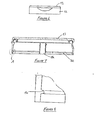
Figure 6 is a front view of a second embodiment of a lid assembly; -
Figure 7 is a cutaway, enlarged view of the lid assembly ofFigure 6 ; -
Figure 8 is an enlarged view of region A ofFigure 7 ; and -
Figure 9 is an expanded view of a second embodiment of a seal. - As indicated above, fixing a lid assembly to a container body by conventional screw-thread means is often ineffective for flowable materials. Moreover, a trend in the cosmetics industry where such containers are widely used is towards containers which can be opened and closed using one hand: a feature which screw-topped containers do not have. In addition manufacture and assembly of a screw-threaded lid assembly can be problematic in respect of the requirement to use the correct amount of turning force on the lid relative to the container body.
- The present invention contemplates a lid assembly which carries a flip-top lid, which assembly can be pushed onto a container body using downward force only. As such, manufacture is simpler and quality control more accurate and more easily assured. The equipment required to carry out the process and to monitor is therefore less expensive.
- In addition, the use of a push on lid enables greater accuracy and consistency in aligning the lid with other features on the container body such as contours to facilitate grip or decoration on the container. Yet further, the lid assembly and the container body can be made of the same material which facilitates recycling.
- Referring to
Figures 1 and 2 these show the basic components of a container, generally referenced 10. Thecontainer 10 has acontainer body 11 to retain the contents and alid assembly 12 which allows the contents to be removed when required and afterwards to close thecontainer 10. Typically the components of thebody 11 and thelid assembly 12 are formed from the same material, which material is advantageously a polypropylene. The lid assembly has alid 13 hingeably mounted by ahinge 14 to thelid assembly 12. Thehinge 14 can be suitably biased to urge thelid 13 to an open or a closed position. To assist the user in lifting thelid 13, theassembly 12 has an indent 15 allowing the user to push thelid 13 from underneath. - In order to retain the
lid assembly 12 in position, thecontainer body 11 has acircumferential clip 16 around itsneck portion 17. As can be seen fromFigure 3 the diameter of theneck portion 17 is smaller than that of the rest of thecontainer body 11 so that the assembledcontainer 10 has a constant diameter throughout its height. In the embodiment ofFigure 4a , theclip 16 has twogaps container body 11. Thegaps lid assembly 12, said ribs passing into thegaps container 10. Once thelid assembly 12 is in position, the edges of thegaps lid assembly 12 with respect to thecontainer body 11. - The
gaps clip 16 can be provided with only one such gap. Thelid assembly 12 is then required to have only one rib. Also, where the orientation is not fully required to be invariant, thegaps container body 11 has adriver rib 21 to aid positioning and orientation when in an assembly machine. - In an alternative embodiment (not illustrated) the or each rib can be located on the outside of the container body, engaging a corresponding gap on the
lid clip 22. It will be recognised that other means known in the art can be used to prevent relative rotary motion of the container body and lid assembly. - Turning to
Figure 5 , this shows thelid assembly 12 in more detail. As indicated above, thelid assembly 12 is attached to thecontainer body 11, theassembly 12 being retained in position at least partially by theclip 16. To this end, theassembly 12 has alid circumferential clip 22 which sits beneath and engages theclip 16. Theassembly 12 is held in position by the resilient nature of the materials from which theassembly 12 is constructed and the resultant resilient forces act to push theskirt 23 towards theneck portion 17. The tensive forces generated during the assembly of the container also act to urge theclip - The seat 24 engages the end of the
neck portion 17, and acts during assembly to prevent thelid assembly 12 from being pushed too far onto thecontainer body 11. Depending from the seat 24 is a seal 25 which has a sealingsurface 26. In use, the sealingsurface 26 engages the inside surface of theneck portion 17 to form a seal preventing egress of the contents between thelid assembly 12 and thecontainer body 11. To assist this thesurface 26 is parallel to theneck portion 17. - The completed
container 10 includes a second seal to prevent the contents from leaking out through the neck of thecontainer 10. Thelid 13 has a circumferential sealingmember 27 which engages acorresponding surface 28 on thelid assembly 12. The sealingmember 27 is formed of a resilient material so that on closure of thelid 13 the sealingmember 27 is urged to remain in sealing contact with theassembly 12. - In order to form the container, the contents are added to the
container body 11. Thecontainer body 11 andlid assembly 12 are brought together such that theassembly 12 is located directly above, at a set distance from thebody 11. Force is then applied - typically a downward force - on the assembly to bring thebody 11 andassembly 12 together. As theassembly 12 passes over thebody 11, theclip 22 first engages from above theclip 16. Continued force results in theclip 22 being forced outwards on theskirt 23 passing over theclip 16. Once theclip 22 has passed beyond the lower edge of theclip 16, the resilient nature of theskirt 23 causes theclip 22 to pass under and remain in engagement with theclip 16. Once the seat 24 engages the end of theneck portion 17, the force is removed. Thecontainer 10, subject to any markings is then eventually ready for dispatch. - A second embodiment of seal is shown in
Figure 6-9 . Where there is a requirement for a sealing wad to be included on manufacture, the above first embodiment can be adapted. As shown particularly inFigure 9 , the second embodiment shares many features with the first embodiment ofFigure 5 ; primarily for example thecircumferential clips lid sealing member 27. - The seat 24 does not however include a seal 25 but instead the contents are prevented from egress by a
wad 29 sandwiched between the seat 24 and theneck portion 17. Thewad 29 can haveperforations 30 or other weakening which permit, on first use by the user, a portion of thewad 29 to be removed. The remaining part of thewad 29 remains, unlike prior art wad seals, between the seat 24 and theneck portion 17 to ensure a seal is retained. In prior art screw-topped containers, the wad would eventually lose its sealing efficiency on continued opening and closing of the container. - Although a number of designs of
wad 29 are known in the art, in a preferred embodiment thewad 29 is a sandwich structure comprising an outer liquid resistant material with a foam material sandwiched therebetween. Said structure of the foam is designed to have self-sealing properties following introduction of the weakening or perforations to prevent material from leaking out or penetrating. - It will of course be understood that the invention is not limited to the specific details described herein, which are given by way of example only, and that various modifications and alterations are possible within the scope of the invention.
Claims (9)
- A flip-lid container (10), the container (10) comprising;
a container body (11) to retain contents such as cosmetic creams or unguents;
the container body (11) having a base (20) and side walls the walls defining an opening through which the contents can be removed,
a lid assembly (12), operatively attached to said body (11) and covering the opening, the lid assembly (12) having a lid (13), hingeably mounted to move between an open and a position in which the opening in the container body is closed,
the lid (13) having a sealing member (27) projecting away from the lid towards, when in the closed position the container body, said member, sealingly engaging a sealing surface (28) on the lid assembly (12) to form a continuous seal about the opening,
the lid assembly sealingly engaging the end of the side walls of the container body;
the lid assembly overlapping and having a complementary shape to the side walls, the overlapping portion of the lid assembly being formed of a resilient material, and including a circumferential clip (22) on its inner surface engaging a corresponding clip (16) on the outer surface of the side wall of the container body to prevent separation of the lid assembly from the container body. - A container according to Claim 1, wherein, the upper surface of the clip (22) on the lid assembly engages the lower surface of the clip (16) on the walls.
- A container according to Claim 1 or Claim 2, wherein the outside of the container side wall or the overlapping portion of the lid assembly includes one or more ribs (19a), located in and engaging the edges of circumferential gaps (18, 19) in the clip to prevent relative rotation of the lid assembly and container body.
- A container according to any preceding Claim, wherein the lid assembly includes a sealing member engaging the inside end of the wall portion to prevent the contents from penetrating between the container body and the lid assembly.
- A container according to Claim 4, wherein the portion of the sealing member and the wall portion forming said engagement are parallel to each other.
- A container according to any preceding claim, wherein the container includes a wad (29), extending across the ends of the side walls to provide a barrier against the contents removed until first required, said wad being sandwiched between the end of the side wall and the lid assembly, the wad additionally forming thereby a seal between the container body and the lid assembly.
- A container according to Claim 6, wherein the wad includes a weakening (30) enabling a portion of the wad to be removed to allow a user to access contents.
- A container according to Claim 7, wherein the weakening comprises a plurality of perforations (30) in the wad.
- A container according to Claims 6-9, wherein the wad has a laminar structure having at least three layers comprising at least one liquid repelling layer and an inner layer of foam based materials which seals on removal of the removable portion to prevent the wad from wicking contents from the container.
Priority Applications (1)
| Application Number | Priority Date | Filing Date | Title |
|---|---|---|---|
| EP20100250699 EP2371729B1 (en) | 2010-03-31 | 2010-03-31 | Hinged lid container |
Applications Claiming Priority (1)
| Application Number | Priority Date | Filing Date | Title |
|---|---|---|---|
| EP20100250699 EP2371729B1 (en) | 2010-03-31 | 2010-03-31 | Hinged lid container |
Publications (2)
| Publication Number | Publication Date |
|---|---|
| EP2371729A1 true EP2371729A1 (en) | 2011-10-05 |
| EP2371729B1 EP2371729B1 (en) | 2012-10-17 |
Family
ID=42169315
Family Applications (1)
| Application Number | Title | Priority Date | Filing Date |
|---|---|---|---|
| EP20100250699 Active EP2371729B1 (en) | 2010-03-31 | 2010-03-31 | Hinged lid container |
Country Status (1)
| Country | Link |
|---|---|
| EP (1) | EP2371729B1 (en) |
Cited By (1)
| Publication number | Priority date | Publication date | Assignee | Title |
|---|---|---|---|---|
| WO2018224434A1 (en) * | 2017-06-07 | 2018-12-13 | Chanel Parfums Beaute | Pot for cosmetic product |
Citations (7)
| Publication number | Priority date | Publication date | Assignee | Title |
|---|---|---|---|---|
| FR2565559A1 (en) * | 1984-06-08 | 1985-12-13 | Seguin Marie Christine | Receptacle with airtight closure for cosmetic products |
| EP0562649A1 (en) * | 1992-03-25 | 1993-09-29 | Agfa-Gevaert N.V. | A cap with an induction seal closure |
| WO2000051904A1 (en) * | 1999-03-03 | 2000-09-08 | Crown Cork & Seal Technologies Corporation | Closure sealing wad |
| EP1157936A2 (en) * | 2000-05-26 | 2001-11-28 | Kraft Foods Holdings, Inc. | Food product container with closure |
| DE20314138U1 (en) * | 2003-09-10 | 2005-01-20 | Henkel Kgaa | Plastic screw cap, in particular for a container containing cosmetics |
| US20080237178A1 (en) * | 2007-01-30 | 2008-10-02 | Betapack, S.A. | Cap for bottles containing edible oil and other food liquids |
| US20090123766A1 (en) * | 2007-11-13 | 2009-05-14 | G3 Enterprises | Modified barrier layers in liners for container closures, capable of providing varible, controlled oxygen ingress |
-
2010
- 2010-03-31 EP EP20100250699 patent/EP2371729B1/en active Active
Patent Citations (7)
| Publication number | Priority date | Publication date | Assignee | Title |
|---|---|---|---|---|
| FR2565559A1 (en) * | 1984-06-08 | 1985-12-13 | Seguin Marie Christine | Receptacle with airtight closure for cosmetic products |
| EP0562649A1 (en) * | 1992-03-25 | 1993-09-29 | Agfa-Gevaert N.V. | A cap with an induction seal closure |
| WO2000051904A1 (en) * | 1999-03-03 | 2000-09-08 | Crown Cork & Seal Technologies Corporation | Closure sealing wad |
| EP1157936A2 (en) * | 2000-05-26 | 2001-11-28 | Kraft Foods Holdings, Inc. | Food product container with closure |
| DE20314138U1 (en) * | 2003-09-10 | 2005-01-20 | Henkel Kgaa | Plastic screw cap, in particular for a container containing cosmetics |
| US20080237178A1 (en) * | 2007-01-30 | 2008-10-02 | Betapack, S.A. | Cap for bottles containing edible oil and other food liquids |
| US20090123766A1 (en) * | 2007-11-13 | 2009-05-14 | G3 Enterprises | Modified barrier layers in liners for container closures, capable of providing varible, controlled oxygen ingress |
Cited By (7)
| Publication number | Priority date | Publication date | Assignee | Title |
|---|---|---|---|---|
| WO2018224434A1 (en) * | 2017-06-07 | 2018-12-13 | Chanel Parfums Beaute | Pot for cosmetic product |
| FR3067228A1 (en) * | 2017-06-07 | 2018-12-14 | Chanel Parfums Beaute | POT FOR COSMETIC PRODUCT |
| CN110799060A (en) * | 2017-06-07 | 2020-02-14 | 香奈儿化妆品简单股份公司 | Cosmetic can |
| KR20200016341A (en) * | 2017-06-07 | 2020-02-14 | 샤넬 파르퓜 보트 | Cosmetic Pot |
| JP2020522443A (en) * | 2017-06-07 | 2020-07-30 | シャネル パルファン ボーテChanel Parfums Beaute | Cosmetic pot |
| CN110799060B (en) * | 2017-06-07 | 2022-05-03 | 香奈儿化妆品简单股份公司 | Cosmetic can |
| US11825927B2 (en) | 2017-06-07 | 2023-11-28 | Chanel Parfums Beaute | Pot for cosmetic product |
Also Published As
| Publication number | Publication date |
|---|---|
| EP2371729B1 (en) | 2012-10-17 |
Similar Documents
| Publication | Publication Date | Title |
|---|---|---|
| RU2326034C2 (en) | Guaranteed hinged stopper for bottles and other containers with liquid substances sealed with film filler material | |
| US10369800B2 (en) | Printing fluid container | |
| RU110363U1 (en) | COOKING PRODUCT TYPE FLIP-TOP AND CAPACITY WITH SUCH COOKING PRODUCT TYPE FLIP-TOP | |
| US20220242621A1 (en) | Closure | |
| US10173816B2 (en) | Closure with a removable membrane having an improved separability configuration | |
| US5111967A (en) | Dispensing closure for a container | |
| CN109720723A (en) | Flip-top pipe with tamper-evident sealing element | |
| JP6243354B2 (en) | Refill container pouring structure | |
| CA3111606A1 (en) | Tethered plastic stopper | |
| GB2127387A (en) | Tamper indicating dispenser | |
| EP2371729B1 (en) | Hinged lid container | |
| GB2467972A (en) | A flip-lid assembly for a container | |
| DE8228681U1 (en) | Tin lid for a can for liquid filling material | |
| US8393491B2 (en) | Neck closure comprising a hermetically sealed neck and associated cover cap for initial opening | |
| HUE033672T2 (en) | Closure system for containers and related container and process for the realization | |
| WO2002040360A1 (en) | Opening device for packaging containers | |
| DE1971458U (en) | EASY TO OPEN AND RE-SEALED CONTAINER. | |
| US3295730A (en) | Rotary flow control closure for a container | |
| EP1999027A2 (en) | A container and method of manufacturing such | |
| JP6736558B2 (en) | Sealing structure for container spout | |
| KR20080047374A (en) | Container, closure means and use thereof | |
| JP5012244B2 (en) | Pouring tap with lid | |
| US3404816A (en) | Pouring means and closure | |
| JP7446057B2 (en) | stopper cap | |
| US20150368010A1 (en) | Liquid container spill proof closure/lid/cap |
Legal Events
| Date | Code | Title | Description |
|---|---|---|---|
| PUAI | Public reference made under article 153(3) epc to a published international application that has entered the european phase |
Free format text: ORIGINAL CODE: 0009012 |
|
| AK | Designated contracting states |
Kind code of ref document: A1 Designated state(s): AT BE BG CH CY CZ DE DK EE ES FI FR GB GR HR HU IE IS IT LI LT LU LV MC MK MT NL NO PL PT RO SE SI SK SM TR |
|
| AX | Request for extension of the european patent |
Extension state: AL BA ME RS |
|
| 17P | Request for examination filed |
Effective date: 20120330 |
|
| GRAP | Despatch of communication of intention to grant a patent |
Free format text: ORIGINAL CODE: EPIDOSNIGR1 |
|
| RIC1 | Information provided on ipc code assigned before grant |
Ipc: A45D 40/22 20060101ALI20120426BHEP Ipc: B65D 43/16 20060101AFI20120426BHEP |
|
| RIN1 | Information on inventor provided before grant (corrected) |
Inventor name: COOK, ROBERT |
|
| GRAS | Grant fee paid |
Free format text: ORIGINAL CODE: EPIDOSNIGR3 |
|
| GRAA | (expected) grant |
Free format text: ORIGINAL CODE: 0009210 |
|
| AK | Designated contracting states |
Kind code of ref document: B1 Designated state(s): AT BE BG CH CY CZ DE DK EE ES FI FR GB GR HR HU IE IS IT LI LT LU LV MC MK MT NL NO PL PT RO SE SI SK SM TR |
|
| REG | Reference to a national code |
Ref country code: GB Ref legal event code: FG4D |
|
| REG | Reference to a national code |
Ref country code: CH Ref legal event code: EP |
|
| REG | Reference to a national code |
Ref country code: IE Ref legal event code: FG4D |
|
| REG | Reference to a national code |
Ref country code: AT Ref legal event code: REF Ref document number: 579794 Country of ref document: AT Kind code of ref document: T Effective date: 20121115 |
|
| REG | Reference to a national code |
Ref country code: DE Ref legal event code: R096 Ref document number: 602010003236 Country of ref document: DE Effective date: 20121220 |
|
| REG | Reference to a national code |
Ref country code: AT Ref legal event code: MK05 Ref document number: 579794 Country of ref document: AT Kind code of ref document: T Effective date: 20121017 |
|
| REG | Reference to a national code |
Ref country code: NL Ref legal event code: VDEP Effective date: 20121017 |
|
| REG | Reference to a national code |
Ref country code: LT Ref legal event code: MG4D |
|
| PG25 | Lapsed in a contracting state [announced via postgrant information from national office to epo] |
Ref country code: LT Free format text: LAPSE BECAUSE OF FAILURE TO SUBMIT A TRANSLATION OF THE DESCRIPTION OR TO PAY THE FEE WITHIN THE PRESCRIBED TIME-LIMIT Effective date: 20121017 Ref country code: NO Free format text: LAPSE BECAUSE OF FAILURE TO SUBMIT A TRANSLATION OF THE DESCRIPTION OR TO PAY THE FEE WITHIN THE PRESCRIBED TIME-LIMIT Effective date: 20130117 Ref country code: NL Free format text: LAPSE BECAUSE OF FAILURE TO SUBMIT A TRANSLATION OF THE DESCRIPTION OR TO PAY THE FEE WITHIN THE PRESCRIBED TIME-LIMIT Effective date: 20121017 Ref country code: SE Free format text: LAPSE BECAUSE OF FAILURE TO SUBMIT A TRANSLATION OF THE DESCRIPTION OR TO PAY THE FEE WITHIN THE PRESCRIBED TIME-LIMIT Effective date: 20121017 Ref country code: IS Free format text: LAPSE BECAUSE OF FAILURE TO SUBMIT A TRANSLATION OF THE DESCRIPTION OR TO PAY THE FEE WITHIN THE PRESCRIBED TIME-LIMIT Effective date: 20130217 Ref country code: HR Free format text: LAPSE BECAUSE OF FAILURE TO SUBMIT A TRANSLATION OF THE DESCRIPTION OR TO PAY THE FEE WITHIN THE PRESCRIBED TIME-LIMIT Effective date: 20121017 Ref country code: FI Free format text: LAPSE BECAUSE OF FAILURE TO SUBMIT A TRANSLATION OF THE DESCRIPTION OR TO PAY THE FEE WITHIN THE PRESCRIBED TIME-LIMIT Effective date: 20121017 |
|
| PG25 | Lapsed in a contracting state [announced via postgrant information from national office to epo] |
Ref country code: GR Free format text: LAPSE BECAUSE OF FAILURE TO SUBMIT A TRANSLATION OF THE DESCRIPTION OR TO PAY THE FEE WITHIN THE PRESCRIBED TIME-LIMIT Effective date: 20130118 Ref country code: LV Free format text: LAPSE BECAUSE OF FAILURE TO SUBMIT A TRANSLATION OF THE DESCRIPTION OR TO PAY THE FEE WITHIN THE PRESCRIBED TIME-LIMIT Effective date: 20121017 Ref country code: PT Free format text: LAPSE BECAUSE OF FAILURE TO SUBMIT A TRANSLATION OF THE DESCRIPTION OR TO PAY THE FEE WITHIN THE PRESCRIBED TIME-LIMIT Effective date: 20130218 Ref country code: SI Free format text: LAPSE BECAUSE OF FAILURE TO SUBMIT A TRANSLATION OF THE DESCRIPTION OR TO PAY THE FEE WITHIN THE PRESCRIBED TIME-LIMIT Effective date: 20121017 Ref country code: PL Free format text: LAPSE BECAUSE OF FAILURE TO SUBMIT A TRANSLATION OF THE DESCRIPTION OR TO PAY THE FEE WITHIN THE PRESCRIBED TIME-LIMIT Effective date: 20121017 Ref country code: BE Free format text: LAPSE BECAUSE OF FAILURE TO SUBMIT A TRANSLATION OF THE DESCRIPTION OR TO PAY THE FEE WITHIN THE PRESCRIBED TIME-LIMIT Effective date: 20121017 |
|
| PG25 | Lapsed in a contracting state [announced via postgrant information from national office to epo] |
Ref country code: AT Free format text: LAPSE BECAUSE OF FAILURE TO SUBMIT A TRANSLATION OF THE DESCRIPTION OR TO PAY THE FEE WITHIN THE PRESCRIBED TIME-LIMIT Effective date: 20121017 |
|
| PG25 | Lapsed in a contracting state [announced via postgrant information from national office to epo] |
Ref country code: DK Free format text: LAPSE BECAUSE OF FAILURE TO SUBMIT A TRANSLATION OF THE DESCRIPTION OR TO PAY THE FEE WITHIN THE PRESCRIBED TIME-LIMIT Effective date: 20121017 Ref country code: SK Free format text: LAPSE BECAUSE OF FAILURE TO SUBMIT A TRANSLATION OF THE DESCRIPTION OR TO PAY THE FEE WITHIN THE PRESCRIBED TIME-LIMIT Effective date: 20121017 Ref country code: EE Free format text: LAPSE BECAUSE OF FAILURE TO SUBMIT A TRANSLATION OF THE DESCRIPTION OR TO PAY THE FEE WITHIN THE PRESCRIBED TIME-LIMIT Effective date: 20121017 Ref country code: CZ Free format text: LAPSE BECAUSE OF FAILURE TO SUBMIT A TRANSLATION OF THE DESCRIPTION OR TO PAY THE FEE WITHIN THE PRESCRIBED TIME-LIMIT Effective date: 20121017 Ref country code: BG Free format text: LAPSE BECAUSE OF FAILURE TO SUBMIT A TRANSLATION OF THE DESCRIPTION OR TO PAY THE FEE WITHIN THE PRESCRIBED TIME-LIMIT Effective date: 20130117 |
|
| PLBE | No opposition filed within time limit |
Free format text: ORIGINAL CODE: 0009261 |
|
| STAA | Information on the status of an ep patent application or granted ep patent |
Free format text: STATUS: NO OPPOSITION FILED WITHIN TIME LIMIT |
|
| PG25 | Lapsed in a contracting state [announced via postgrant information from national office to epo] |
Ref country code: IT Free format text: LAPSE BECAUSE OF FAILURE TO SUBMIT A TRANSLATION OF THE DESCRIPTION OR TO PAY THE FEE WITHIN THE PRESCRIBED TIME-LIMIT Effective date: 20121017 Ref country code: RO Free format text: LAPSE BECAUSE OF FAILURE TO SUBMIT A TRANSLATION OF THE DESCRIPTION OR TO PAY THE FEE WITHIN THE PRESCRIBED TIME-LIMIT Effective date: 20121017 |
|
| 26N | No opposition filed |
Effective date: 20130718 |
|
| REG | Reference to a national code |
Ref country code: DE Ref legal event code: R119 Ref document number: 602010003236 Country of ref document: DE |
|
| PG25 | Lapsed in a contracting state [announced via postgrant information from national office to epo] |
Ref country code: ES Free format text: LAPSE BECAUSE OF FAILURE TO SUBMIT A TRANSLATION OF THE DESCRIPTION OR TO PAY THE FEE WITHIN THE PRESCRIBED TIME-LIMIT Effective date: 20130128 Ref country code: MC Free format text: LAPSE BECAUSE OF NON-PAYMENT OF DUE FEES Effective date: 20130331 |
|
| REG | Reference to a national code |
Ref country code: DE Ref legal event code: R097 Ref document number: 602010003236 Country of ref document: DE Effective date: 20130718 |
|
| PG25 | Lapsed in a contracting state [announced via postgrant information from national office to epo] |
Ref country code: CY Free format text: LAPSE BECAUSE OF FAILURE TO SUBMIT A TRANSLATION OF THE DESCRIPTION OR TO PAY THE FEE WITHIN THE PRESCRIBED TIME-LIMIT Effective date: 20121017 |
|
| REG | Reference to a national code |
Ref country code: IE Ref legal event code: MM4A |
|
| REG | Reference to a national code |
Ref country code: DE Ref legal event code: R119 Ref document number: 602010003236 Country of ref document: DE Effective date: 20131001 |
|
| PG25 | Lapsed in a contracting state [announced via postgrant information from national office to epo] |
Ref country code: IE Free format text: LAPSE BECAUSE OF NON-PAYMENT OF DUE FEES Effective date: 20130331 Ref country code: DE Free format text: LAPSE BECAUSE OF NON-PAYMENT OF DUE FEES Effective date: 20131001 |
|
| PG25 | Lapsed in a contracting state [announced via postgrant information from national office to epo] |
Ref country code: MT Free format text: LAPSE BECAUSE OF FAILURE TO SUBMIT A TRANSLATION OF THE DESCRIPTION OR TO PAY THE FEE WITHIN THE PRESCRIBED TIME-LIMIT Effective date: 20121017 |
|
| REG | Reference to a national code |
Ref country code: CH Ref legal event code: PL |
|
| PG25 | Lapsed in a contracting state [announced via postgrant information from national office to epo] |
Ref country code: LI Free format text: LAPSE BECAUSE OF NON-PAYMENT OF DUE FEES Effective date: 20140331 Ref country code: CH Free format text: LAPSE BECAUSE OF NON-PAYMENT OF DUE FEES Effective date: 20140331 |
|
| PG25 | Lapsed in a contracting state [announced via postgrant information from national office to epo] |
Ref country code: SM Free format text: LAPSE BECAUSE OF FAILURE TO SUBMIT A TRANSLATION OF THE DESCRIPTION OR TO PAY THE FEE WITHIN THE PRESCRIBED TIME-LIMIT Effective date: 20121017 |
|
| PG25 | Lapsed in a contracting state [announced via postgrant information from national office to epo] |
Ref country code: TR Free format text: LAPSE BECAUSE OF FAILURE TO SUBMIT A TRANSLATION OF THE DESCRIPTION OR TO PAY THE FEE WITHIN THE PRESCRIBED TIME-LIMIT Effective date: 20121017 |
|
| PG25 | Lapsed in a contracting state [announced via postgrant information from national office to epo] |
Ref country code: HU Free format text: LAPSE BECAUSE OF FAILURE TO SUBMIT A TRANSLATION OF THE DESCRIPTION OR TO PAY THE FEE WITHIN THE PRESCRIBED TIME-LIMIT; INVALID AB INITIO Effective date: 20100331 Ref country code: MK Free format text: LAPSE BECAUSE OF FAILURE TO SUBMIT A TRANSLATION OF THE DESCRIPTION OR TO PAY THE FEE WITHIN THE PRESCRIBED TIME-LIMIT Effective date: 20121017 Ref country code: LU Free format text: LAPSE BECAUSE OF NON-PAYMENT OF DUE FEES Effective date: 20130331 |
|
| REG | Reference to a national code |
Ref country code: FR Ref legal event code: PLFP Year of fee payment: 7 |
|
| REG | Reference to a national code |
Ref country code: FR Ref legal event code: PLFP Year of fee payment: 8 |
|
| REG | Reference to a national code |
Ref country code: FR Ref legal event code: PLFP Year of fee payment: 9 |
|
| PGFP | Annual fee paid to national office [announced via postgrant information from national office to epo] |
Ref country code: FR Payment date: 20230127 Year of fee payment: 14 |
|
| PGFP | Annual fee paid to national office [announced via postgrant information from national office to epo] |
Ref country code: GB Payment date: 20230126 Year of fee payment: 14 |