EP2371687A1 - Electrical accessory mounting device for a saddle-type vehicle - Google Patents
Electrical accessory mounting device for a saddle-type vehicle Download PDFInfo
- Publication number
- EP2371687A1 EP2371687A1 EP11159112A EP11159112A EP2371687A1 EP 2371687 A1 EP2371687 A1 EP 2371687A1 EP 11159112 A EP11159112 A EP 11159112A EP 11159112 A EP11159112 A EP 11159112A EP 2371687 A1 EP2371687 A1 EP 2371687A1
- Authority
- EP
- European Patent Office
- Prior art keywords
- saddle
- type vehicle
- electrical accessory
- mounting device
- holding portion
- Prior art date
- Legal status (The legal status is an assumption and is not a legal conclusion. Google has not performed a legal analysis and makes no representation as to the accuracy of the status listed.)
- Granted
Links
- 239000002828 fuel tank Substances 0.000 claims description 10
- 238000003780 insertion Methods 0.000 description 21
- 230000037431 insertion Effects 0.000 description 21
- 230000004048 modification Effects 0.000 description 10
- 238000012986 modification Methods 0.000 description 10
- 125000006850 spacer group Chemical group 0.000 description 8
- 230000000694 effects Effects 0.000 description 5
- 230000006835 compression Effects 0.000 description 3
- 238000007906 compression Methods 0.000 description 3
- 230000001276 controlling effect Effects 0.000 description 1
- 230000001105 regulatory effect Effects 0.000 description 1
Images







Classifications
-
- B—PERFORMING OPERATIONS; TRANSPORTING
- B62—LAND VEHICLES FOR TRAVELLING OTHERWISE THAN ON RAILS
- B62J—CYCLE SADDLES OR SEATS; AUXILIARY DEVICES OR ACCESSORIES SPECIALLY ADAPTED TO CYCLES AND NOT OTHERWISE PROVIDED FOR, e.g. ARTICLE CARRIERS OR CYCLE PROTECTORS
- B62J11/00—Supporting arrangements specially adapted for fastening specific devices to cycles, e.g. supports for attaching maps
-
- B—PERFORMING OPERATIONS; TRANSPORTING
- B62—LAND VEHICLES FOR TRAVELLING OTHERWISE THAN ON RAILS
- B62J—CYCLE SADDLES OR SEATS; AUXILIARY DEVICES OR ACCESSORIES SPECIALLY ADAPTED TO CYCLES AND NOT OTHERWISE PROVIDED FOR, e.g. ARTICLE CARRIERS OR CYCLE PROTECTORS
- B62J50/00—Arrangements specially adapted for use on cycles not provided for in main groups B62J1/00 - B62J45/00
- B62J50/20—Information-providing devices
- B62J50/21—Information-providing devices intended to provide information to rider or passenger
- B62J50/225—Mounting arrangements therefor
-
- B—PERFORMING OPERATIONS; TRANSPORTING
- B62—LAND VEHICLES FOR TRAVELLING OTHERWISE THAN ON RAILS
- B62J—CYCLE SADDLES OR SEATS; AUXILIARY DEVICES OR ACCESSORIES SPECIALLY ADAPTED TO CYCLES AND NOT OTHERWISE PROVIDED FOR, e.g. ARTICLE CARRIERS OR CYCLE PROTECTORS
- B62J9/00—Containers specially adapted for cycles, e.g. panniers or saddle bags
- B62J9/20—Containers specially adapted for cycles, e.g. panniers or saddle bags attached to the cycle as accessories
- B62J9/25—Containers specially adapted for cycles, e.g. panniers or saddle bags attached to the cycle as accessories to the fuel tank, e.g. magnetic tank bags
Definitions
- the present invention is related to an electrical accessory mounting device for a saddle-type vehicle.
- US Patent No. 6378815 discloses this kind of mounting device where a shaft is inserted into a steering stem pipe and then fixed thereto, and a plate is pivotally provided on an upper section of the shaft, and an electrical accessory such as a radar detector is detachably provided on the plate.
- Japanese Patent Registered Publication No. 3608753 discloses an electrical accessory mounting device for a two-wheeled vehicle which comprises a fixture mounted on a steering portion or a tank of a two-wheeled vehicle and a supporting portion supporting an electrical accessory, where the fixture is provided on a center line of a two-wheeled vehicle body extending in the longitudinal direction of the two-wheeled vehicle; and the supporting portion is so mounted on the fixture that it can pivot about a lateral axis of the fixture and is clamped to be fixed to a handle bar by screwing an upper fastener into a lower fastener and then tightening them with a bolt, thus allowing the bolt to fix the fixture.
- the supporting portion when a mounting position is lowered, the supporting portion must be arranged upward away from a fastener or the like because the electrical accessory is easy to contact the fastener in pivoting the supporting portion downward.
- the position and angle need to be adjusted with a view to avoiding glaring reflection of the sun light and interference with indicators of the two-wheeled vehicle.
- a mounting device with a bag for a navigation apparatus provided on a fuel tank has conventionally been proposed.
- an object of the present invention to provide an electrical accessory mounting device for a saddle-type vehicle capable of adjusting the position of the electrical accessory such that a rider can easily check the electrical accessory visually.
- the present invention provides an electrical accessory mounting device for a saddle-type vehicle (1) to mount an electrical accessory (20) to a steering member (3) of the saddle-type vehicle (1) or a vehicle body in front of a seat thereof comprising: a fixture (4,61) mounted on the saddle-type vehicle (1); and a holding portion (5,62) holding the electrical accessory (20), characterized in that:
- the electrical accessory mounting device for a saddle-type vehicle is characterized in further comprising an angular setting means (37) making at least part of said holding portion (5) movable relative to said fixture (4) in a longitudinal direction of the saddle-type vehicle (1), and setting an angle of said holding portion (5) to a predetermined angle according to a position corresponding to the movement of said holding portion (5) in the longitudinal direction.
- the electrical accessory mounting device for a saddle-type vehicle is characterized in that said angular setting means (37) allows said holding portion (5) to move in parallel or an upper section thereof to rotate rearwardly of the vehicle (1) when said holding portion (5) is moved from back to front.
- the electrical accessory mounting device for a saddle-type vehicle is characterized in that said angular setting means comprises a pair of guides (34, 35) provided on one of said fixture (4) and said holding portion (5), and a pair of movement portions (36F, 36B) provided on the other of said fixture (4) and said holding portion (5), said movement portions (36F, 36B) moving along a pair of said guides (34, 35).
- the electrical accessory mounting device for a saddle-type vehicle is characterized in that each of said guides (34,35) is a long hole while each of said movement portions (36F, 36B) is a screw movable along said long holes (34,35).
- the electrical accessory mounting device for a saddle-type vehicle is characterized in that a pair of said guides (34, 35) are arranged in crossing directions.
- the electrical accessory mounting device for a saddle-type vehicle is characterized in that said fixture (61) is mounted on a fuel tank (51) of the saddle-type vehicle (1) with a tank bag (52), and that said holding portion (62) is provided so as to be movable relative to said tank bag (52) in a longitudinal direction of the saddle-type vehicle (1) so that it may come in and out of a front of said tank bag (52).
- the electrical accessory mounting device for a saddle-type vehicle is characterized in that said holding portion (62) comprises a sliding member (68) movable in the longitudinal direction of the vehicle (1) relative to said tank bag (52).
- the mounting device enables the position of the electrical accessory to be made viewable by the rider through the back-and-forth movement of the holding portion in the longitudinal direction of the vehicle.
- the mounting device enables an angle of said holding portion to be set to a predetermined angle by movement of said holding portion, thus allowing the electrical accessory to be adjusted to an easily viewable position where other members do not interfere.
- the mounting device enables the position and angle of the electrical accessory to be set by moving the electrical accessory either in parallel or from back to front so as to rotate the same.
- the mounting device enables the setting of the angle of the holding portion by engaging the guides with the movement portions.
- the mounting device enables the setting of the angle of the holding portion by a simple structure in which the long hole and the screw are engaged with each other.
- the mounting device enables setting of the angle of the holding portion while allowing the holding portion to move, since a pair of said guides are arranged in the crossing directions.
- the mounting device enables the electrical accessory to be housed in the tank bag when the holding portion is retracted backward, while it enables the electrical accessory to be viewed and used by taking the electrical accessory out from the front of the tank bag when the holding portion is advanced to the front.
- the mounting device enables the electrical accessory to come in and out from the tank bag by sliding the holding portion.
- an electrical accessory mounting device of the present embodiment comprises: a steering stem pipe 3 located at the substantial rotational center of a steering portion 2 for a saddle-type vehicle 1 as a two-wheeled vehicle; a metallic fixture 4 fixed on the steering stem pipe 3; and a bracket 5 as a holding portion provided on the fixture 4 in such a manner that the position of the bracket 5 can be adjusted.
- the fixture 4 includes a receiving portion 6 receiving the bracket 5 in a position-adjustable manner and an insertion portion 7 which is inserted into the steering stem pipe 3 and then fixed thereto.
- the receiving portion 6 and the insertion portion 7 are metallic.
- the receiving portion 6 has a side plate 9 on both lateral sides of a base 8 and is formed in a U-shape whose upper portion is open.
- the insertion portion 7 includes an insertion pipe 10 integrally formed on the base 8 at the center of the bottom face thereof.
- the base 8 has a through-hole 11 drilled at the center thereof so that the through-hole 11 is communicated with the insertion pipe 10. From the through-hole 11, a long bolt 12 is inserted into the insertion pipe 10.
- the inner diameter of the insertion pipe 10 is approximately half the outer diameter thereof such that its pipe wall is formed thick.
- the insertion pipe 10 has an inclined surface 10A obliquely formed at the lower end thereof.
- a nut body 13 connected thereto by the long bolt 1.
- an inclined surface 13A that is formed so as to correspond to the inclined surface 10A.
- These inclined surfaces 10A, 13A are each at approximately 45 degrees relative to the center axis of the insertion pipe 10.
- the outer diameters of the insertion pipe 10 and the nut body 13 are slightly smaller than the inner diameter of the steering stem pipe 3, thereby allowing them to be inserted into the steering stem pipe 3.
- numeral 14 designates a cylindrical cover body covering the upper portion of the steering stem pipe 3.
- the cover body 14 has a top face and is made of an elastic member. At the center of the top face of the cover body 14, there is provided an insertion hole 15 into which the insertion pipe 10 and the nut body 13 are inserted.
- the cover body 14 is provided as needs arise.
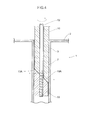
- the insertion pipe 10 and the nut body 13 are inserted into the steering stem pipe 3 from the top open thereof, followed by the adjustment of the height of the fixture 4 and the orientation thereof to the longitudinal direction of the vehicle 1. Specifically, the orientation of the side plates is adjusted so as to coincide with the longitudinal direction of the vehicle 1. After that, as shown in FIG. 4 , the inclined surfaces 10A, 13A are pressed against each other by further screwing the long bolt 12 into the nut body 13.
- the lower end of the inclined surface 10A is allowed to slightly move toward the inner surface of the steering stem pipe 3; on the other, the upper end of the inclined surface 13A is allowed to slightly move toward the inner surface thereof.
- the inclined surfaces 10A, 13A are each pressed onto the inner wall of the insertion pipe 10, thereby allowing the fixture 4 to be fixed to the steering stem pipe 3.
- the bracket 5 comprises an attachment portion 21 attaching a navigation apparatus 20 thereto and side plates 22, 22 provided integrally with the attachment portion 21 on the lateral sides thereof.
- the bracket 5 has an inverted U-shape whose lower portion is open. These side plates 22, 22 are inserted between the side plates 9, 9 of the fixture 4. Note that the attachment portion 21 and the side plates 22, 22 are metallic.
- the navigation apparatus 20 comprises a navigation display 20A displaying navigational information such as a destination and current vehicle position, a controller controlling the navigation display 20A, and an operation portion for a user to perform an input operation to the controller.
- a plurality of attachment holes 23 are drilled in the attachment portion 21.
- an elastic cylindrical body 29 is fixed thereto by an attachment member 28 including a bolt 24, nut 25, washer 26, collar 27 and so on.
- the elastic cylindrical body 29 includes a hard inner cylindrical body 30 thereinside.
- An attachment 31 for the navigation apparatus 20 is fixed on a front of the elastic cylindrical body 29 with the former abutting on the latter.
- a fitting groove 29A is provided around the periphery of a rear portion of the elastic cylindrical body 29 so that it engages with the attachment hole 23.
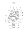
- FIG. 3 shows the device prior to mounting the attachment 31.
- the navigation apparatus 20 can be mounted on the attachment 31 in a snap-on manner. On the contrary, the navigation apparatus 20 can be removed by operating an operation portion not shown in the drawings.
- the side plates 22, 22 of the bracket 5 are formed with female screw holes 32, 32 provided on the front and the rear thereof at a certain interval.
- the female screw hole 32 is composed of a nut 33 fixed on the inside surface of the side plate 22.
- long holes 34, 35 serving as guides are formed on the front and rear of the side plate 9 of the fixture 4 so as to correspond to the female screw holes 32, 32.
- a front-side screw 36F as a front-side movement portion, and then the front-side screw 36F is screwed into the corresponding female screw hole 32.
- a rear-side screw 36B as a rear-side movement portion, and then the rear-side screw 36B is screwed into the corresponding female screw hole 32.
- the front-side screw 36F and the rear-side screw 36B serving as lateral shafts, become movable within the front-side long hole 34 and the rear-side long hole 35, respectively.
- the front-side long hole 34 is formed longer than the rear-side long hole 35 in this embodiment.
- the navigation apparatus 20 is mounted on a steering member of the vehicle 1 or a front side of the vehicle body.
- the navigation apparatus 20 is mounted on the steering stem pipe 3 which constitutes a part of the steering member.
- front-side long hole 34, rear-side long hole 35, front-side screw 36F and rear-side screw 36B constitute an angular setting means 37 so that it may be used to adjust an angle of the bracket 5 through the back-and forth movement of the front-side screw 36F and the rear-side screw 36B within the long holes 34, 35 respectively.
- the front-side long hole 34 is substantially vertically elongated, while the rear-side long hole 35 is substantially horizontally elongated, and both of the long holes 34, 35 are formed in a substantially circular arc shape. And then, the front-side screw 36F is allowed to move within the front-side long hole 34, and the rear-side screw 36B to move within the rear-side long hole 35.
- the front-side screw 36F is allowed to move within the front-side long hole 34, and the rear-side screw 36B to move within the rear-side long hole 35.
- the bracket 5 serving as a holding portion is set at a predetermined angle by allowing the front-side screw 36F and the rear-side screw 36B to move within the front-side long hole 34 and the rear-side long hole 35, respectively, unlike the prior art where an electrical accessory has a singe rotational center on the rearside thereof Accordingly, the navigation apparatus 20 can be adjusted at the position and angle suitable for use conditions because the navigation apparatus 20 as an electrical accessory faces squarely to the rider even when the bracket 5 moves back and forth or up and down during the adjustment thereof.
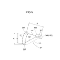
- the center of the rear-side screw 36B at the rear end of the rear-side long hole 35 and the center of the front-side screw 36F at the upper-end of the front-side long hole 34 are connected with each other via a pre-rotation imaginary line 101.
- An angle of the imaginary line 101 to the horizontal direction corresponds to the angle of the navigation apparatus 20.
- the length of the imaginary line 101 corresponds to an interval K between the front-side screw 36F and the rear-side screw 36B.
- the position of the rear-side screw 36B at the rear end of the rear-side long hole 35 is assumed to correspond to a center axis 100 of the prior art in which rotation takes place about only one axis. Accordingly, the imaginary line 101 is common to the present embodiment and the prior art.
- a post-rotation imaginary line 102 is defined as a line connecting between positions of the front-side screw 36F and the rear-side screw 36B after the front-side screw 36F moves to the lower end of the front-side long hole 34 and the rear-side screw 36B moves to the front end of rear-side long hole 35.
- a post-rotation imaginary line 103 is defined as a line rotated about the center axis 100 by the same angle as that between the pre-rotation imaginary line 101 and the post-rotation imaginary line 102.
- the rotation about the fixed center axis 100 requires a height H
- the rotation by the two-axis-sliding system requires a height h, thereby demonstrating that using the two-axis-sliding system enables the reduction of a vertical space required for rotation of the navigation apparatus 20 when rotating it by the same angle.
- FIG. 5 is only shown by way of explanation of function, and relative positions of the long holes 34, 35 are unchanged between FIG. 1 and FIG. 5 .
- numeral 41 designates a cylindrical spacer provided on a seam between the insertion pipe 10 and the nut body 13.
- the spacer 41 is provided with a vertical groove 42 extending over an entire length thereof in the longitudinal direction, and the outer diameter of the spacer 41 corresponds to the inner diameter of the steering stem pipe 3. Accordingly, when the long bolt 12 is screwed into the nut body 13, both of the inclined surfaces 10A, 13A are pressed against each other, and due to the wedge effect at that time, the lower end of the inclined surface 10A is allowed to move slightly outwardly toward the inner surface of the steering stem pipe 3, while the upper end of the inclined surface 13A is allowed to move slightly outwardly toward the inner surface thereof.
- the spacer 41 having the vertical groove 42 is expanded, and the outer circumference of the spacer 41 is pressed to the inner of the steering stem pipe 3.
- the fixture 4 is fixed onto the steering stem pipe 3. In this way, the same insertion pipe 10 and the nut body 13 can be used for a steering stem pipe 3 having various diameters.
- the electrical accessory mounting device for a saddle-type vehicle 1 to mount the navigation apparatus 20 as an electrical accessory to the steering stem pipe 3 as a steering member of the saddle-type vehicle comprising: the fixture 4 mounted on the saddle-type vehicle 1; the bracket 5 as a holding portion holding the electrical accessory 20; and the angular setting means 37 making at least part of the bracket 5 movable relative to the fixture 4 in the longitudinal direction of the saddle-type vehicle 1 and setting an angle of the bracket 5 to a predetermined angle according to a position corresponding to the movement of the bracket 5 in the longitudinal direction.
- the mounting device of the present embodiment is able to set the angle of the bracket 5 to a predetermined angle by the back-and-forth movement of the bracket 5, and thus allowing the electrical accessory 20 to be adjusted to an easily viewable position where other members do not interfere.
- the angular setting means 37 is structured such that the upper section of the bracket 5 rotates rearwardly of the vehicle 1 when the bracket 5 as a holding portion moves from back to front.
- the mounting device is able to adjust the position and angle of the navigation apparatus 20 by rotating the navigation apparatus 20 in backward.
- the angular setting means 37 comprises a pair of long holes 34, 35 as guides provided on the fixture 4 as one of the fixture 4 and the bracket 5, and a pair of screws 36F, 36B moving along a pair of long holes 34, 35 and being provided on the bracket 5 as the other of the fixture 4 and the bracket 5.
- the mounting device is able to set the angle of the bracket 5 by engaging the long holes 34, 35 with the screws 36F, 36B.
- the mounting device is able to set the angle of the bracket 5 using a simple structure in which the long holes 34, 35 and the screws 36F, 36B are engaged.
- the mounting device is able to allow the bracket 5 as a holding portion to move along the long holes 34, 35 and set the angle thereof.
- the navigation apparatus 20 can be easily mounted on the steering stem pipe 3 by adjusting the height and orientation of the fixture 4.
- the bracket 5 is provided with the elastic cylindrical body 29 arranged between the attachment portion 21 of the bracket 5 and the navigation apparatus 20, the effect of vibration against the navigation apparatus 20 can be reduced.
- FIG.6 and FIG.7 A second embodiment of the present invention is shown in FIG.6 and FIG.7 .
- the same reference numbers are used to describe the same parts as those in the first embodiment, thereby omitting the detailed descriptions of such parts when describing the second embodiment.
- the fixture 4 is fixed on a steering handlebar (not shown) having a circular outer circumference, using a steering handlebar clamping means 44, instead of using the insertion portion 7 of the fixture 4 in the foregoing embodiment.
- the steering handlebar clamping means 44 has a right-and-left pair of clamps 45, 45.
- the clamp 45 includes a pair of circular-arc-shaped split pieces 46, 46. First end faces 47 of the split pieces 46 are abutted to each other, while a space as a tightening margin is provided between second end faces 47A, 47A of the split pieces 46. Additionally, a female screw hole 48 is drilled at the end of one split piece 46, and a through- hole 48A is drilled at the end of the other split piece 46, corresponding to the one split piece 46.
- Another through-hole 48B is drilled at the base 8 of the receiving portion 6, and a bolt 50 is inserted from the through-hole 48B through a cylindrical collar 49 into the through-hole 48A, and then screwed into the female screw hole 48. This causes the clamps 45, 45 to clamp the steering handlebar located between the split pieces 46, 46. Furthermore, when the bolt 50 is loosened, the angle of the steering handlebar clamping means 44 can be adjusted by rotating the fixture 4 about the steering handlebar.
- the fixture 4 includes the steering handlebar clamping means 44, thus enabling the angle of the fixture 4 to the steering handlebar to be adjusted.
- FIG.8 through FIG. 14 A third embodiment of the present invention is shown in FIG.8 through FIG. 14 .
- the same reference numbers are used to describe the same parts as those in the first embodiment, thereby omitting the detailed descriptions of such parts when describing the third embodiment.
- modifications relating to the arrangement of a guide are described.
- the long holes 34, 35 are formed in a substantially linear fashion and are arranged at a predetermined angle.
- long holes 34, 35 are arranged at substantially right angels relative to each other such that when the lower side of the bracket 5 is moved forward, the navigation apparatus 20 is allowed to stand nearly upright as shown by the post-rotation imaginary line 102.
- FIG. 10 due to the post-rotation imaginary line 102 being perpendicular to the longitudinal axis of the long hole 34, the front-side-screw 36F does not move back and forth as shown in FIG. 9 .
- FIG. 11 when the front-side screw 36F moves from the position of the imaginary line 102 to the position of the imaginary line 101, the rear-side-screw 36B slightly moves backward and then moves forward.
- the bracket 5 is moved backward, thereby allowing the upper part of the navigation apparatus 20 to rotate backward.
- the long hole 34 is curved.
- both of the long holes 34, 35 are partially arranged in parallel.
- the width of the rear-side long hole 35 is formed narrower than that of the front-side long hole 34, and a part of the long holes 34, 35 are shared.
- the rear-side screw 36B is formed in a smaller diameter. In this way, the widths of the long-holes 34, 35 are formed different from each other and the diameters of the screws 36F, 36B are formed in a different size such that the larger diameter screw 36F is guided along the front-side long hole 34 while the smaller diameter screw 36B is guided along the rear-side long hole 35. According to the modifications in FIG. 12 and FIG.
- the screws 36F, 36B are allowed to move in a parallel fashion in a linear part 35S on the rear end of the rear-side long hole 35, and the navigation apparatus 20 goes flatline during the parallel movement. On the other hand, in the position of the imaginary line 102, the navigation apparatus 20 goes vertical.
- FIG. 14 it is structured such that the screws 36F, 36B are allowed to move in a single long hole 43 as a guide, and thus the screws 36F, 36B move in a parallel fashion at the lower part of the long hole 43.
- the navigation apparatus 20 can be mounted according to the alignment of indicators around the steering portion 2.
- the angular setting means 37 is allowed to move in a parallel fashion when the bracket 5 as a holding portion is moved from back to front, and thus the navigation apparatus 20 as an electrical accessory moves in a parallel fashion, thereby allowing the position thereof to be adjusted, in accordance with the second aspect of the present invention.
- the angular setting means 37 comprises the long hole 43 as a guide provided on the fixture 4, and the screws 36F, 36B as a pair of movement portions moving along the long hole 43, whereby, according to the second aspect of the invention, the angular setting means 37 is structured such that the upper section of the bracket 5 is allowed to rotate rearwardly of the vehicle 1 when the bracket 5 as a holding portion is moved from back to front, thus enabling the position and angle of the navigation apparatus 20 to be adjusted by rotating the navigation apparatus 20 forward.
- FIG.15 through FIG.19 A fourth embodiment of the present invention is shown in FIG.15 through FIG.19 .
- the same reference numbers are used to describe the same parts as those in the first embodiment, thereby omitting the detailed descriptions of such parts when describing the fourth embodiment.
- a substantially rectangular fuel tank bag 52 elongated in the longitudinal direction of the vehicle 1 is mounted on a fuel tank 51 of the vehicle 1.
- the tank bag 52 comprises a bottom face 53, side faces 54, 54, 55, 55 on the front, back, right and left sides, and a top face 56.
- an openable portion 58 having a zipper 57 is provided on the front, right and left side faces 54, 55, 55 such that a cover 59 on the top of the openable portion 58 can be opened. By opening the cover 59, at least the front side face 54 can be opened.
- tank bag 52 is fixed on the upper front of the fuel tank by using a fastening means (not shown) such as magnet or belt.
- a fixture 61 fixed on the bottom face 53, said fixture 61 being fixed on the fuel tank 51 by mounting the tank bag 52 to the fuel tank 51, while a holding portion 62 is slidably provided on the fixture 61.
- the fixture 61 includes a base 64 having a slide hole 63 extending in the longitudinal direction of the tank bag 52.
- the base 64 is formed such that right and left spacer plates 66, 66 are placed between upper and lower plates 65, 65 and fixed by screws 67 thereto, thereby forming a slide hole 63 between the right and left spacer plates 66, 66.
- the holding portion 62 has a sliding member 68 capable of sliding within the slide hole 63, and the front end of the sliding member 68 is integrally provided with an attachment portion 69 whose top face is inclined forward. And the aforesaid attachment 31 is mounted on the top face of the attachment portion 69. Further, on the rear side of the sliding member 68, there is formed a stopper 70 regulating the forward movement of the sliding member 68, said stopper 70 being formed by folding the sliding member 68. The stopper 70 engages with the rear end of the base 64, thereby limiting the further forward movement of the sliding member 68.
- a positioning means 71 is provided for positioning the holding portion 62 relative to the fixture 61.
- the positioning means 71 comprises front and back locking concave portions 72, 72A provided on the inner edge of the spacer plate 66, a laterally elongated concave portion 73 provided on the outer edge of the sliding member 68 corresponding to these locking concave portions 72, 72A, a compression spring 74 as a biasing means inserted into the concave portion 73, and a ball 75 as a locking insert member engageably inserted into the concave portions 72, 72A while being biased by the compression spring 74.
- the positioning means 71 can position the sliding member 68 where the ball 75 is inserted into the locking concave portions 72, 72A.
- the locking concave portion 72 on the front side corresponds to the forward position where the navigation apparatus 20 comes forward out of the tank bag 52
- the locking concave portion 72A on the rear side corresponds to the backward position where the navigation apparatus 20 is placed in the tank bag 52.
- the navigation apparatus 20 can be arranged on the front of the tank bag 52 by opening the cover 59 and pulling out the apparatus 20, while the navigation apparatus 20 can be placed in the tank bag 52 with the cover 59 being closed.
- the electrical accessory mounting device for a saddle-type vehicle to mount the navigation apparatus 20 as an electrical accessory to the vehicle body 1 in front of a seat comprising: the fixture 61 mounted on the fuel tank 51 of the saddle-type vehicle 1 with the tank bag 52, and the holding portion 62 holding the navigation apparatus 20, the holding portion 62 being movable relative to the tank bag 52 in a longitudinal direction of the saddle-type vehicle 1 so that it may come in and out of a front of said tank bag 52.
- the navigation apparatus 20 can be stored in the tank bag 52 at the position where the holding portion 62 is retreated backward. Also, the navigation apparatus 20 can be used and visually recognized by advancing and taking the same out of the tank bag 52.
- the holding portion 62 comprises the sliding member 68 movable in the longitudinal direction of the vehicle 1 relative to said tank bag 52, the navigation apparatus 20 can be allowed to come in and out from the tank bag 52 by sliding the holding portion 62.
- the electrical accessory mounting device of the present invention comprises the positioning means 71 positioning the holding portion 62 relative to the fixture 61 and thus the navigation apparatus 20 can be easily positioned at any of a use position and a storage position.
- FIG.20 and FIG.21 A fifth embodiment of the present invention is shown in FIG.20 and FIG.21 .
- the same reference numbers are used to describe the same parts as those in the first embodiment, thereby omitting the detailed descriptions of such parts when describing the fifth embodiment.
- a modification of the tank bag 52 is shown.
- a substantially U-shaped cover 59A which corresponds to the width of the navigation apparatus 20 is provided on the front side face 54, and the top of the cover 59A is connected to the aforesaid top face 56.
- the zipper 57 for opening and closing the cover 59A has two opening-closing sliders 81, 81, and the slider 81 has a gripper 82 as an operation portion.
- both sides of the cover 59A and the lower side thereof except for the part of the slide member 68 can be zipped by sliding the sliders 81, 81.
- a cover 59B is so structured that it covers almost a whole surface of the front side face 54, and the top of the cover 59B is connected to the top face 56.
- both sides of the cover 59B and the lower side of the cover 59B except for the part of the slide member 68 can be zipped by sliding the sliders 81, 81.
- vehicles referred to as the saddle-type vehicle of the invention may include any two-wheeled vehicles, snowmobiles and four-wheeled motorcycles.
- those referred to as the electrical accessory may include various things other than the navigation apparatus, and the present invention is preferably applicable to those having a display portion.
- the mounting device of the navigation apparatus 20 mounted on the steering stem pipe 3 of the saddle-type vehicle 1 comprises the fixture 4 mounted on the saddle-type vehicle 1, the bracket 5 holding the navigation apparatus 20, and the angular setting means 37 making at least part of the bracket 5 movable to the fixture 4 in the longitudinal direction of the saddle-type vehicle 1 and setting an angle of the bracket 5 to a predetermined angle by the position corresponding to the movement of the bracket 5.
- the angular setting means 37 includes a pair of long holes 34, 35 provided on the fixture 4 and a pair of screws 36F, 36B moving along a pair of long holes 34, 35 provided on the bracket 5.
Landscapes
- Engineering & Computer Science (AREA)
- Mechanical Engineering (AREA)
- Steering Devices For Bicycles And Motorcycles (AREA)
- Fittings On The Vehicle Exterior For Carrying Loads, And Devices For Holding Or Mounting Articles (AREA)
Abstract
Description
- The present invention is related to an electrical accessory mounting device for a saddle-type vehicle.
- Conventionally,
US Patent No. 6378815 , for example, discloses this kind of mounting device where a shaft is inserted into a steering stem pipe and then fixed thereto, and a plate is pivotally provided on an upper section of the shaft, and an electrical accessory such as a radar detector is detachably provided on the plate. - Further, Japanese Patent Registered Publication No.
3608753 - According to the mounting devices mentioned above, there is a concern about the degraded visibility of indicators such as a speed meter, a turn signal indicator, and a display of gear-position, since the electrical accessory is mounted on the upper section of a steering portion.
- Furthermore, according to the foregoing structure which allows the supporting portion to pivot about the lateral axis of the fixture as disclosed in the latter prior art relating to the above electrical accessory mounting device for a two-wheeled vehicle, when a mounting position is lowered, the supporting portion must be arranged upward away from a fastener or the like because the electrical accessory is easy to contact the fastener in pivoting the supporting portion downward. Moreover, in the cast that there is one rotating axis at the rear side of the electrical accessory, then there will exist the only one position where the electrical accessory squarely faces a rider, and practically, the position and angle need to be adjusted with a view to avoiding glaring reflection of the sun light and interference with indicators of the two-wheeled vehicle.
- Meanwhile, a mounting device with a bag for a navigation apparatus provided on a fuel tank has conventionally been proposed. However, it is difficult for a rider to visually check the navigation apparatus while riding a two-wheeled vehicle because the navigation apparatus is arranged along the fuel tank and thus the rider must look down at the navigation apparatus.
- Accordingly, in view of the problems above, it is an object of the present invention to provide an electrical accessory mounting device for a saddle-type vehicle capable of adjusting the position of the electrical accessory such that a rider can easily check the electrical accessory visually.
- In order to achieve the object, the present invention according to a first aspect of the invention provides an electrical accessory mounting device for a saddle-type vehicle (1) to mount an electrical accessory (20) to a steering member (3) of the saddle-type vehicle (1) or a vehicle body in front of a seat thereof comprising: a fixture (4,61) mounted on the saddle-type vehicle (1); and a holding portion (5,62) holding the electrical accessory (20), characterized in that:
- said holding portion (5,62) is provided so as to be movable in a longitudinal direction of the saddle-type vehicle (1).
- The electrical accessory mounting device for a saddle-type vehicle according to a second aspect of the present invention is characterized in further comprising an angular setting means (37) making at least part of said holding portion (5) movable relative to said fixture (4) in a longitudinal direction of the saddle-type vehicle (1), and setting an angle of said holding portion (5) to a predetermined angle according to a position corresponding to the movement of said holding portion (5) in the longitudinal direction.
- The electrical accessory mounting device for a saddle-type vehicle according to a third aspect of the present invention is characterized in that said angular setting means (37) allows said holding portion (5) to move in parallel or an upper section thereof to rotate rearwardly of the vehicle (1) when said holding portion (5) is moved from back to front.
- The electrical accessory mounting device for a saddle-type vehicle according to a fourth aspect of the present invention is characterized in that said angular setting means comprises a pair of guides (34, 35) provided on one of said fixture (4) and said holding portion (5), and a pair of movement portions (36F, 36B) provided on the other of said fixture (4) and said holding portion (5), said movement portions (36F, 36B) moving along a pair of said guides (34, 35).
- The electrical accessory mounting device for a saddle-type vehicle according to a fifth aspect of the present invention is characterized in that each of said guides (34,35) is a long hole while each of said movement portions (36F, 36B) is a screw movable along said long holes (34,35).
- The electrical accessory mounting device for a saddle-type vehicle according to a sixth aspect of the present invention is characterized in that a pair of said guides (34, 35) are arranged in crossing directions.
- The electrical accessory mounting device for a saddle-type vehicle according to a seventh aspect of the present invention is characterized in that said fixture (61) is mounted on a fuel tank (51) of the saddle-type vehicle (1) with a tank bag (52), and that said holding portion (62) is provided so as to be movable relative to said tank bag (52) in a longitudinal direction of the saddle-type vehicle (1) so that it may come in and out of a front of said tank bag (52).
- The electrical accessory mounting device for a saddle-type vehicle according to an eighth aspect of the present invention is characterized in that said holding portion (62) comprises a sliding member (68) movable in the longitudinal direction of the vehicle (1) relative to said tank bag (52).
- According to the first aspect of the present invention, the mounting device enables the position of the electrical accessory to be made viewable by the rider through the back-and-forth movement of the holding portion in the longitudinal direction of the vehicle.
- According to the second aspect of the present invention, the mounting device enables an angle of said holding portion to be set to a predetermined angle by movement of said holding portion, thus allowing the electrical accessory to be adjusted to an easily viewable position where other members do not interfere.
- According to the third aspect of the present invention, the mounting device enables the position and angle of the electrical accessory to be set by moving the electrical accessory either in parallel or from back to front so as to rotate the same.
- According to the fourth aspect of the present invention, the mounting device enables the setting of the angle of the holding portion by engaging the guides with the movement portions.
- According to the fifth aspect of the present invention, the mounting device enables the setting of the angle of the holding portion by a simple structure in which the long hole and the screw are engaged with each other.
- According to the sixth aspect of the present invention, the mounting device enables setting of the angle of the holding portion while allowing the holding portion to move, since a pair of said guides are arranged in the crossing directions.
- According to the seventh aspect of the present invention, the mounting device enables the electrical accessory to be housed in the tank bag when the holding portion is retracted backward, while it enables the electrical accessory to be viewed and used by taking the electrical accessory out from the front of the tank bag when the holding portion is advanced to the front.
- According to the eighth aspect of the present invention, the mounting device enables the electrical accessory to come in and out from the tank bag by sliding the holding portion.
-
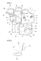
FIG. 1 is a perspective view of an electrical accessory mounting device for a saddle-type vehicle according to a first embodiment of the present invention. -
FIG. 2 is an exploded perspective view of the device according to the first embodiment. -
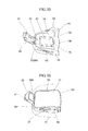
FIG. 3 is a perspective view of the device prior to mounting the electrical accessory thereto according to the first embodiment. -
FIG. 4 is a cross-section view showing an insertion portion inside a steering stem pipe according to the first embodiment. -
FIG. 5 is an explanatory view to explain a function of an angle setting means according to a modification of the first embodiment. -
FIG. 6 is an exploded perspective view of a device according to a second embodiment. -
FIG. 7 is a perspective view of the device prior to mounting the electrical accessory thereto according to the second embodiment. -
FIG. 8 is an explanatory view to explain a function of an angle setting means according to a third embodiment. -
FIG. 9 is an explanatory view to explain a function of an angle setting means according to a modification of the third embodiment. -
FIG. 10 is an explanatory view to explain a function of an angle setting means according to another modification of the third embodiment. -
FIG. 11 is an explanatory view to explain a function of an angle setting means according to another modification of the third embodiment. -
FIG. 12 is an explanatory view to explain a function of an angle setting means according to another modification of the third embodiment. -
FIG. 13 is an explanatory view to explain a function of an angle setting means according to another modification of the third embodiment. -
FIG. 14 is an explanatory view to explain a function of an angle setting means according to another modification of the third embodiment. -
FIG. 15 is a perspective view of a device according to a fourth embodiment. -
FIG. 16 is a perspective view showing the electrical accessory being out of a tank bag according to the fourth embodiment. -
FIG. 17 is a plan view of a main section according to the fourth embodiment. -
FIG. 18 is a plan view of the main section with a holding portion being moved forward according to the fourth embodiment. -
FIG. 19 is a cross-section of the main section according to the fourth embodiment. -
FIG. 20 is a front view showing the tank bag according to the fourth embodiment. -
FIG. 21 is a front view showing another tank bag according to the fourth embodiment. - As follows is a detailed description of preferred embodiments of the present invention with reference to the appended drawings.
- As shown in
FIG. 1 to FIG. 5 , an electrical accessory mounting device of the present embodiment comprises: asteering stem pipe 3 located at the substantial rotational center of asteering portion 2 for a saddle-type vehicle 1 as a two-wheeled vehicle; ametallic fixture 4 fixed on thesteering stem pipe 3; and abracket 5 as a holding portion provided on thefixture 4 in such a manner that the position of thebracket 5 can be adjusted. - The
fixture 4 includes a receivingportion 6 receiving thebracket 5 in a position-adjustable manner and aninsertion portion 7 which is inserted into thesteering stem pipe 3 and then fixed thereto. Thereceiving portion 6 and theinsertion portion 7 are metallic. - The
receiving portion 6 has aside plate 9 on both lateral sides of abase 8 and is formed in a U-shape whose upper portion is open. Further, theinsertion portion 7 includes aninsertion pipe 10 integrally formed on thebase 8 at the center of the bottom face thereof. Thebase 8 has a through-hole 11 drilled at the center thereof so that the through-hole 11 is communicated with theinsertion pipe 10. From the through-hole 11, along bolt 12 is inserted into theinsertion pipe 10. The inner diameter of theinsertion pipe 10 is approximately half the outer diameter thereof such that its pipe wall is formed thick. Theinsertion pipe 10 has aninclined surface 10A obliquely formed at the lower end thereof. At the bottom of theinsertion pipe 10, there is provided anut body 13 connected thereto by thelong bolt 1. At an upper portion of thenut body 13, there is provided aninclined surface 13A that is formed so as to correspond to theinclined surface 10A. Theseinclined surfaces insertion pipe 10. Furthermore, the outer diameters of theinsertion pipe 10 and thenut body 13 are slightly smaller than the inner diameter of thesteering stem pipe 3, thereby allowing them to be inserted into thesteering stem pipe 3. - In the drawing,
numeral 14 designates a cylindrical cover body covering the upper portion of thesteering stem pipe 3. Thecover body 14 has a top face and is made of an elastic member. At the center of the top face of thecover body 14, there is provided aninsertion hole 15 into which theinsertion pipe 10 and thenut body 13 are inserted. Thecover body 14 is provided as needs arise. - Then, with the
nut body 13 being temporarily fixed to theinsertion pipe 10 by thelong bolt 12 after allowing the inclined faces 10A, 13A to mate with each other, theinsertion pipe 10 and thenut body 13 are inserted into thesteering stem pipe 3 from the top open thereof, followed by the adjustment of the height of thefixture 4 and the orientation thereof to the longitudinal direction of thevehicle 1. Specifically, the orientation of the side plates is adjusted so as to coincide with the longitudinal direction of thevehicle 1. After that, as shown inFIG. 4 , theinclined surfaces long bolt 12 into thenut body 13. Through a so-called wedge effect, on the one hand, the lower end of theinclined surface 10A is allowed to slightly move toward the inner surface of thesteering stem pipe 3; on the other, the upper end of theinclined surface 13A is allowed to slightly move toward the inner surface thereof. As a result, theinclined surfaces insertion pipe 10, thereby allowing thefixture 4 to be fixed to thesteering stem pipe 3. - Next, the
bracket 5 is described in detail. Thebracket 5 comprises anattachment portion 21 attaching anavigation apparatus 20 thereto andside plates attachment portion 21 on the lateral sides thereof. Thebracket 5 has an inverted U-shape whose lower portion is open. Theseside plates side plates fixture 4. Note that theattachment portion 21 and theside plates navigation apparatus 20 comprises anavigation display 20A displaying navigational information such as a destination and current vehicle position, a controller controlling thenavigation display 20A, and an operation portion for a user to perform an input operation to the controller. - A plurality of attachment holes 23 (more than three holes; in this embodiment, four holes) are drilled in the
attachment portion 21. In eachattachment hole 23, an elasticcylindrical body 29 is fixed thereto by anattachment member 28 including abolt 24,nut 25,washer 26,collar 27 and so on. The elasticcylindrical body 29 includes a hard innercylindrical body 30 thereinside. Anattachment 31 for thenavigation apparatus 20 is fixed on a front of the elasticcylindrical body 29 with the former abutting on the latter. Further, afitting groove 29A is provided around the periphery of a rear portion of the elasticcylindrical body 29 so that it engages with theattachment hole 23. In addition,FIG. 3 shows the device prior to mounting theattachment 31. - The
navigation apparatus 20 can be mounted on theattachment 31 in a snap-on manner. On the contrary, thenavigation apparatus 20 can be removed by operating an operation portion not shown in the drawings. - The
side plates bracket 5 are formed with female screw holes 32, 32 provided on the front and the rear thereof at a certain interval. Thefemale screw hole 32 is composed of anut 33 fixed on the inside surface of theside plate 22. Further,long holes side plate 9 of thefixture 4 so as to correspond to the female screw holes 32, 32. Into the front-sidelong hole 34 is inserted a front-side screw 36F as a front-side movement portion, and then the front-side screw 36F is screwed into the correspondingfemale screw hole 32. Similarly, into the rear-sidelong hole 35 is inserted a rear-side screw 36B as a rear-side movement portion, and then the rear-side screw 36B is screwed into the correspondingfemale screw hole 32. In this way, the front-side screw 36F and the rear-side screw 36B, serving as lateral shafts, become movable within the front-sidelong hole 34 and the rear-sidelong hole 35, respectively. Incidentally, the front-sidelong hole 34 is formed longer than the rear-sidelong hole 35 in this embodiment. - Thus, the
navigation apparatus 20 is mounted on a steering member of thevehicle 1 or a front side of the vehicle body. In this embodiment, thenavigation apparatus 20 is mounted on thesteering stem pipe 3 which constitutes a part of the steering member. - These front-side
long hole 34, rear-sidelong hole 35, front-side screw 36F and rear-side screw 36B constitute an angular setting means 37 so that it may be used to adjust an angle of thebracket 5 through the back-and forth movement of the front-side screw 36F and the rear-side screw 36B within thelong holes - According to the present embodiment, the front-side
long hole 34 is substantially vertically elongated, while the rear-sidelong hole 35 is substantially horizontally elongated, and both of thelong holes side screw 36F is allowed to move within the front-sidelong hole 34, and the rear-side screw 36B to move within the rear-sidelong hole 35. Thus, as shown inFIG. 1 , when the rear-side screw 36B moves backward from the front end of the rear-sidelong hole 35 within the rear-sidelong hole 35, the front-side screw 36F moves downward from the upper end of the front-sidelong hole 34 within the front-sidelong hole 34, thereby allowing thenavigation apparatus 20 to rotate in such a manner that the upper part of thedisplay 20A of thenavigation apparatus 20 moves downward. Conversely, when the lower part of thebracket 5 moves forward, the upper part of thenavigation apparatus 20 rotates backward, thereby allowing thenavigation apparatus 20 to stand upright. - As described above, according to the present embodiment, the
bracket 5 serving as a holding portion is set at a predetermined angle by allowing the front-side screw 36F and the rear-side screw 36B to move within the front-sidelong hole 34 and the rear-sidelong hole 35, respectively, unlike the prior art where an electrical accessory has a singe rotational center on the rearside thereof Accordingly, thenavigation apparatus 20 can be adjusted at the position and angle suitable for use conditions because thenavigation apparatus 20 as an electrical accessory faces squarely to the rider even when thebracket 5 moves back and forth or up and down during the adjustment thereof. - Next, the difference between the two-axis-sliding system using the front-
side screw 36F and the rear-side screw 36B according to the present embodiment and the conventional system in which rotation takes place about only one axis is described below with reference toFIG. 5 . InFIG. 5 , the center of the rear-side screw 36B at the rear end of the rear-sidelong hole 35 and the center of the front-side screw 36F at the upper-end of the front-sidelong hole 34 are connected with each other via a pre-rotationimaginary line 101. An angle of theimaginary line 101 to the horizontal direction corresponds to the angle of thenavigation apparatus 20. Note that the length of theimaginary line 101 corresponds to an interval K between the front-side screw 36F and the rear-side screw 36B. Also, the position of the rear-side screw 36B at the rear end of the rear-sidelong hole 35 is assumed to correspond to acenter axis 100 of the prior art in which rotation takes place about only one axis. Accordingly, theimaginary line 101 is common to the present embodiment and the prior art. Here, a post-rotationimaginary line 102 is defined as a line connecting between positions of the front-side screw 36F and the rear-side screw 36B after the front-side screw 36F moves to the lower end of the front-sidelong hole 34 and the rear-side screw 36B moves to the front end of rear-sidelong hole 35. Also, a post-rotationimaginary line 103 is defined as a line rotated about thecenter axis 100 by the same angle as that between the pre-rotationimaginary line 101 and the post-rotationimaginary line 102. As is clearly shown from the illustrations of theseimaginary lines center axis 100 requires a height H, while the rotation by the two-axis-sliding system requires a height h, thereby demonstrating that using the two-axis-sliding system enables the reduction of a vertical space required for rotation of thenavigation apparatus 20 when rotating it by the same angle. Incidentally,FIG. 5 is only shown by way of explanation of function, and relative positions of thelong holes FIG. 1 andFIG. 5 . - In
FIG. 1 andFIG. 3 , numeral 41 designates a cylindrical spacer provided on a seam between theinsertion pipe 10 and thenut body 13. Thespacer 41 is provided with avertical groove 42 extending over an entire length thereof in the longitudinal direction, and the outer diameter of thespacer 41 corresponds to the inner diameter of thesteering stem pipe 3. Accordingly, when thelong bolt 12 is screwed into thenut body 13, both of theinclined surfaces inclined surface 10A is allowed to move slightly outwardly toward the inner surface of thesteering stem pipe 3, while the upper end of theinclined surface 13A is allowed to move slightly outwardly toward the inner surface thereof. Thus, thespacer 41 having thevertical groove 42 is expanded, and the outer circumference of thespacer 41 is pressed to the inner of thesteering stem pipe 3. As a result, thefixture 4 is fixed onto thesteering stem pipe 3. In this way, thesame insertion pipe 10 and thenut body 13 can be used for asteering stem pipe 3 having various diameters. - As described above, according to the first aspect of the present invention, the electrical accessory mounting device for a saddle-
type vehicle 1 to mount thenavigation apparatus 20 as an electrical accessory to thesteering stem pipe 3 as a steering member of the saddle-type vehicle comprising: thefixture 4 mounted on the saddle-type vehicle 1; thebracket 5 as a holding portion holding theelectrical accessory 20; and the angular setting means 37 making at least part of thebracket 5 movable relative to thefixture 4 in the longitudinal direction of the saddle-type vehicle 1 and setting an angle of thebracket 5 to a predetermined angle according to a position corresponding to the movement of thebracket 5 in the longitudinal direction. Thus, the mounting device of the present embodiment is able to set the angle of thebracket 5 to a predetermined angle by the back-and-forth movement of thebracket 5, and thus allowing theelectrical accessory 20 to be adjusted to an easily viewable position where other members do not interfere. - According to the second aspect, the angular setting means 37 is structured such that the upper section of the
bracket 5 rotates rearwardly of thevehicle 1 when thebracket 5 as a holding portion moves from back to front. Thus, the mounting device is able to adjust the position and angle of thenavigation apparatus 20 by rotating thenavigation apparatus 20 in backward. - According to the third and fourth aspects, the angular setting means 37 comprises a pair of
long holes fixture 4 as one of thefixture 4 and thebracket 5, and a pair ofscrews long holes bracket 5 as the other of thefixture 4 and thebracket 5. Thus, the mounting device is able to set the angle of thebracket 5 by engaging thelong holes screws - According to the fifth and sixth aspects, since guides are
long holes screws long holes bracket 5 using a simple structure in which thelong holes screws - According to the seventh to tenth aspects, since a pair of the
long holes bracket 5 as a holding portion to move along thelong holes - Specifically, according to the present embodiment, since the
inclined surface 10A is formed on the lower end of theinsertion pipe 10, and theinclined surface 13A corresponding to theinclined surface 10A is formed on the upper end of thenut body 13, and the mounting device of the present invention has a swage fixing means expanding outward by pressing both of theinclined surfaces long bolt 12 as a screwing means, thenavigation apparatus 20 can be easily mounted on thesteering stem pipe 3 by adjusting the height and orientation of thefixture 4. Moreover, since thebracket 5 is provided with the elasticcylindrical body 29 arranged between theattachment portion 21 of thebracket 5 and thenavigation apparatus 20, the effect of vibration against thenavigation apparatus 20 can be reduced. - A second embodiment of the present invention is shown in
FIG.6 andFIG.7 . The same reference numbers are used to describe the same parts as those in the first embodiment, thereby omitting the detailed descriptions of such parts when describing the second embodiment. According to this embodiment, thefixture 4 is fixed on a steering handlebar (not shown) having a circular outer circumference, using a steering handlebar clamping means 44, instead of using theinsertion portion 7 of thefixture 4 in the foregoing embodiment. - The steering handlebar clamping means 44 has a right-and-left pair of
clamps clamp 45 includes a pair of circular-arc-shapedsplit pieces split pieces 46 are abutted to each other, while a space as a tightening margin is provided between second end faces 47A, 47A of thesplit pieces 46. Additionally, afemale screw hole 48 is drilled at the end of onesplit piece 46, and a through-hole 48A is drilled at the end of theother split piece 46, corresponding to the onesplit piece 46. - Another through-
hole 48B is drilled at thebase 8 of the receivingportion 6, and abolt 50 is inserted from the through-hole 48B through acylindrical collar 49 into the through-hole 48A, and then screwed into thefemale screw hole 48. This causes theclamps split pieces bolt 50 is loosened, the angle of the steering handlebar clamping means 44 can be adjusted by rotating thefixture 4 about the steering handlebar. - As described above, according to the present embodiment, it is possible to achieve the same function and effect as the first embodiment. Specifically according to the present embodiment, the
fixture 4 includes the steering handlebar clamping means 44, thus enabling the angle of thefixture 4 to the steering handlebar to be adjusted. - A third embodiment of the present invention is shown in
FIG.8 through FIG. 14 . The same reference numbers are used to describe the same parts as those in the first embodiment, thereby omitting the detailed descriptions of such parts when describing the third embodiment. According to the present embodiment, modifications relating to the arrangement of a guide are described. InFIG. 8 to FIG. 11 , thelong holes - In
FIG. 8 ,long holes bracket 5 is moved forward, thenavigation apparatus 20 is allowed to stand nearly upright as shown by the post-rotationimaginary line 102. - In
FIG. 9 , when the front-side-screw 36F is moved upward within thelong hole 34 from the position of theimaginary line 101, the front-side-screw 36B slightly moves backward at first and then moves forward up to the position of theimaginary line 102. - In
FIG. 10 , due to the post-rotationimaginary line 102 being perpendicular to the longitudinal axis of thelong hole 34, the front-side-screw 36F does not move back and forth as shown inFIG. 9 . On the other hand, inFIG. 11 , when the front-side screw 36F moves from the position of theimaginary line 102 to the position of theimaginary line 101, the rear-side-screw 36B slightly moves backward and then moves forward. InFIG. 10 and FIG. 11 , thebracket 5 is moved backward, thereby allowing the upper part of thenavigation apparatus 20 to rotate backward. - In
FIG. 12 and FIG. 13 , thelong hole 34 is curved. InFIG. 12 , both of thelong holes FIG. 13 , the width of the rear-sidelong hole 35 is formed narrower than that of the front-sidelong hole 34, and a part of thelong holes side screw 36B is formed in a smaller diameter. In this way, the widths of the long-holes screws larger diameter screw 36F is guided along the front-sidelong hole 34 while thesmaller diameter screw 36B is guided along the rear-sidelong hole 35. According to the modifications inFIG. 12 and FIG. 13 , thescrews linear part 35S on the rear end of the rear-sidelong hole 35, and thenavigation apparatus 20 goes flatline during the parallel movement. On the other hand, in the position of theimaginary line 102, thenavigation apparatus 20 goes vertical. - Further, in
FIG. 14 , it is structured such that thescrews long hole 43 as a guide, and thus thescrews long hole 43. - In this way, through the movement along the two axes along the guide(s), various layouts become possible. As a result, the
navigation apparatus 20 can be mounted according to the alignment of indicators around thesteering portion 2. - As described above, according to the present embodiment, it is possible to achieve the same function and effect as the first embodiment. Specifically according to the present embodiment, as shown in
FIG. 12 and FIG. 13 , the angular setting means 37 is allowed to move in a parallel fashion when thebracket 5 as a holding portion is moved from back to front, and thus thenavigation apparatus 20 as an electrical accessory moves in a parallel fashion, thereby allowing the position thereof to be adjusted, in accordance with the second aspect of the present invention. - Also, as shown in
FIG. 14 , the angular setting means 37 comprises thelong hole 43 as a guide provided on thefixture 4, and thescrews long hole 43, whereby, according to the second aspect of the invention, the angular setting means 37 is structured such that the upper section of thebracket 5 is allowed to rotate rearwardly of thevehicle 1 when thebracket 5 as a holding portion is moved from back to front, thus enabling the position and angle of thenavigation apparatus 20 to be adjusted by rotating thenavigation apparatus 20 forward. - A fourth embodiment of the present invention is shown in
FIG.15 through FIG.19 . The same reference numbers are used to describe the same parts as those in the first embodiment, thereby omitting the detailed descriptions of such parts when describing the fourth embodiment. According to this embodiment, a substantially rectangularfuel tank bag 52 elongated in the longitudinal direction of thevehicle 1 is mounted on afuel tank 51 of thevehicle 1. Thetank bag 52 comprises abottom face 53, side faces 54, 54, 55, 55 on the front, back, right and left sides, and atop face 56. According to this embodiment, anopenable portion 58 having azipper 57 is provided on the front, right and left side faces 54, 55, 55 such that acover 59 on the top of theopenable portion 58 can be opened. By opening thecover 59, at least the front side face 54 can be opened. - Further, the
tank bag 52 is fixed on the upper front of the fuel tank by using a fastening means (not shown) such as magnet or belt. - In the inside of the
tank bag 52, there is provided afixture 61 fixed on thebottom face 53, saidfixture 61 being fixed on thefuel tank 51 by mounting thetank bag 52 to thefuel tank 51, while a holdingportion 62 is slidably provided on thefixture 61. - The
fixture 61 includes a base 64 having aslide hole 63 extending in the longitudinal direction of thetank bag 52. Thebase 64 is formed such that right and leftspacer plates lower plates screws 67 thereto, thereby forming aslide hole 63 between the right and leftspacer plates - The holding
portion 62 has a slidingmember 68 capable of sliding within theslide hole 63, and the front end of the slidingmember 68 is integrally provided with anattachment portion 69 whose top face is inclined forward. And theaforesaid attachment 31 is mounted on the top face of theattachment portion 69. Further, on the rear side of the slidingmember 68, there is formed astopper 70 regulating the forward movement of the slidingmember 68, saidstopper 70 being formed by folding the slidingmember 68. Thestopper 70 engages with the rear end of thebase 64, thereby limiting the further forward movement of the slidingmember 68. - Moreover, a positioning means 71 is provided for positioning the holding
portion 62 relative to thefixture 61. The positioning means 71 comprises front and back lockingconcave portions spacer plate 66, a laterally elongatedconcave portion 73 provided on the outer edge of the slidingmember 68 corresponding to these lockingconcave portions compression spring 74 as a biasing means inserted into theconcave portion 73, and aball 75 as a locking insert member engageably inserted into theconcave portions compression spring 74. And, when a force larger than a predetermined force is applied to the slidingmember 68, theball 75 is pushed into theconcave portion 73 against the biasing force of thecompression spring 74 and thus the slidingmember 68 becomes movable. Thus, the positioning means 71 can position the slidingmember 68 where theball 75 is inserted into the lockingconcave portions - The locking
concave portion 72 on the front side corresponds to the forward position where thenavigation apparatus 20 comes forward out of thetank bag 52, and the lockingconcave portion 72A on the rear side corresponds to the backward position where thenavigation apparatus 20 is placed in thetank bag 52. In this way, thenavigation apparatus 20 can be arranged on the front of thetank bag 52 by opening thecover 59 and pulling out theapparatus 20, while thenavigation apparatus 20 can be placed in thetank bag 52 with thecover 59 being closed. - As described above, according to the present embodiment, there is provided the electrical accessory mounting device for a saddle-type vehicle to mount the
navigation apparatus 20 as an electrical accessory to thevehicle body 1 in front of a seat, according to the sixth aspect of the invention, comprising: thefixture 61 mounted on thefuel tank 51 of the saddle-type vehicle 1 with thetank bag 52, and the holdingportion 62 holding thenavigation apparatus 20, the holdingportion 62 being movable relative to thetank bag 52 in a longitudinal direction of the saddle-type vehicle 1 so that it may come in and out of a front of saidtank bag 52. - Accordingly, the
navigation apparatus 20 can be stored in thetank bag 52 at the position where the holdingportion 62 is retreated backward. Also, thenavigation apparatus 20 can be used and visually recognized by advancing and taking the same out of thetank bag 52. - As such, according to the present embodiment, as depicted in the seventh aspect of the invention, the holding
portion 62 comprises the slidingmember 68 movable in the longitudinal direction of thevehicle 1 relative to saidtank bag 52, thenavigation apparatus 20 can be allowed to come in and out from thetank bag 52 by sliding the holdingportion 62. - Specifically, according to the present embodiment, the electrical accessory mounting device of the present invention comprises the positioning means 71 positioning the holding
portion 62 relative to thefixture 61 and thus thenavigation apparatus 20 can be easily positioned at any of a use position and a storage position. - A fifth embodiment of the present invention is shown in
FIG.20 and FIG.21 . The same reference numbers are used to describe the same parts as those in the first embodiment, thereby omitting the detailed descriptions of such parts when describing the fifth embodiment. According to this embodiment, a modification of thetank bag 52 is shown. InFIG. 20 , a substantiallyU-shaped cover 59A which corresponds to the width of thenavigation apparatus 20 is provided on thefront side face 54, and the top of thecover 59A is connected to the aforesaidtop face 56. Furthermore, thezipper 57 for opening and closing thecover 59A has two opening-closingsliders slider 81 has agripper 82 as an operation portion. As shown inFIG. 20 , after thenavigation apparatus 20 is taken out to the front of thetank bag 52, both sides of thecover 59A and the lower side thereof except for the part of theslide member 68 can be zipped by sliding thesliders - Moreover, in
FIG. 21 , acover 59B is so structured that it covers almost a whole surface of thefront side face 54, and the top of thecover 59B is connected to thetop face 56. As shown inFIG. 21 , after thenavigation apparatus 20 is taken out to the front of thetank bag 52, both sides of thecover 59B and the lower side of thecover 59B except for the part of theslide member 68 can be zipped by sliding thesliders - The present invention is not limited to the aforementioned embodiments. Various embodiments are possible without departing from the spirit and scope of the present invention. For example, vehicles referred to as the saddle-type vehicle of the invention may include any two-wheeled vehicles, snowmobiles and four-wheeled motorcycles. In addition, those referred to as the electrical accessory may include various things other than the navigation apparatus, and the present invention is preferably applicable to those having a display portion.
- There is provided an electrical accessory mounting device capable of adjusting an electrical accessory to the position viewable from a rider. The mounting device of the
navigation apparatus 20 mounted on thesteering stem pipe 3 of the saddle-type vehicle 1 comprises thefixture 4 mounted on the saddle-type vehicle 1, thebracket 5 holding thenavigation apparatus 20, and the angular setting means 37 making at least part of thebracket 5 movable to thefixture 4 in the longitudinal direction of the saddle-type vehicle 1 and setting an angle of thebracket 5 to a predetermined angle by the position corresponding to the movement of thebracket 5. The angular setting means 37 includes a pair oflong holes fixture 4 and a pair ofscrews long holes bracket 5. Thus, the angle of thenavigation apparatus 20 can be adjusted by back-and-forth movement of thebracket 5, thereby allowing the electrical accessory to be adjusted to an easily viewable position where other members do not interfere.
Claims (8)
- An electrical accessory mounting device for a saddle-type vehicle (1) to mount an electrical accessory (20) to a steering member (3) of the saddle-type vehicle (1) or a vehicle body in front of a seat thereof comprising: a fixture (4,61) mounted on the saddle-type vehicle (1); and a holding portion (5,62) holding the electrical accessory (20), characterized in that:said holding portion (5,62) is provided so as to be movable in a longitudinal direction of the saddle-type vehicle (1).
- The electrical accessory mounting device for a saddle-type vehicle (1) according to claim 1, characterized in further comprising an angular setting means (37) making at least part of said holding portion (5) movable relative to said fixture (4) in a longitudinal direction of the saddle-type vehicle (1), and setting an angle of said holding portion (5) to a predetermined angle according to a position corresponding to the movement of said holding portion (5) in the longitudinal direction.
- The electrical accessory mounting device for a saddle-type vehicle according to claim 2, characterized in that said angular setting means (37) allows said holding portion (5) to move in parallel or an upper section thereof to rotate rearwardly of the vehicle (1) when said holding portion (5) is moved from back to front.
- The electrical accessory mounting device for a saddle-type vehicle according to claim 2 or 3, characterized in that said angular setting means (37) comprises a pair of guides (34, 35) provided on one of said fixture (4) and said holding portion (5), and a pair of movement portions (36F, 36B) provided on the other of said fixture (4) and said holding portion (5), said movement portions (36F, 36B) moving along a pair of said guides (34, 35).
- The electrical accessory mounting device for a saddle-type vehicle according to claim 4, characterized in that each of said guides (34,35) is a long hole while each of said movement portions (36F, 36B) is a screw movable along said long holes (34,35).
- The electrical accessory mounting device for a saddle-type vehicle according to claim 4 or 5, characterized in that a pair of said guides (34, 35) are arranged in crossing directions.
- The electrical accessory mounting device for a saddle-type vehicle according to claim 1, characterized in that:said fixture (61) is mounted on a fuel tank (51) of the saddle-type vehicle (1) with a tank bag (52), and that said holding portion (62) is provided so as to be movable relative to said tank bag (52) in a longitudinal direction of the saddle-type vehicle (1) so that it may come in and out of a front of said tank bag (52).
- The electrical accessory mounting device for a saddle-type vehicle according to claim 7, characterized in that said holding portion (62) comprises a sliding member (68) movable in the longitudinal direction of the vehicle (1) relative to said tank bag (52).
Applications Claiming Priority (1)
| Application Number | Priority Date | Filing Date | Title |
|---|---|---|---|
| JP2010072979A JP5569860B2 (en) | 2010-03-26 | 2010-03-26 | Electrical component mounting device for saddle riding type vehicles |
Publications (2)
| Publication Number | Publication Date |
|---|---|
| EP2371687A1 true EP2371687A1 (en) | 2011-10-05 |
| EP2371687B1 EP2371687B1 (en) | 2012-08-29 |
Family
ID=43971537
Family Applications (1)
| Application Number | Title | Priority Date | Filing Date |
|---|---|---|---|
| EP11159112A Not-in-force EP2371687B1 (en) | 2010-03-26 | 2011-03-22 | Electrical accessory mounting device for a saddle-type vehicle |
Country Status (4)
| Country | Link |
|---|---|
| US (1) | US8627990B2 (en) |
| EP (1) | EP2371687B1 (en) |
| JP (1) | JP5569860B2 (en) |
| ES (1) | ES2390613T3 (en) |
Cited By (4)
| Publication number | Priority date | Publication date | Assignee | Title |
|---|---|---|---|---|
| CN104760642A (en) * | 2015-03-11 | 2015-07-08 | 天津金轮自行车集团有限公司 | Mobile phone fixing frame for bicycle |
| WO2018078192A1 (en) * | 2016-10-27 | 2018-05-03 | Nad, S.L. | Mounting system for accessories on a motorbike |
| EP3819198A1 (en) * | 2019-11-05 | 2021-05-12 | SW-Motech GmbH & Co. KG | Adapter for attaching objects to the tank of a motorcycle |
| CN112810737A (en) * | 2021-03-17 | 2021-05-18 | 常州市武进华瑞电子有限公司 | Electric motor car instrument mounting structure |
Families Citing this family (47)
| Publication number | Priority date | Publication date | Assignee | Title |
|---|---|---|---|---|
| JP6158478B2 (en) * | 2012-05-16 | 2017-07-05 | 本田技研工業株式会社 | Non-contact charging structure of portable information terminal in vehicle |
| JP6033003B2 (en) * | 2012-08-24 | 2016-11-30 | 本田技研工業株式会社 | Storage structure for saddle-ride type vehicles |
| DE202013007384U1 (en) * | 2012-08-29 | 2013-09-12 | Harald Richter | Equipment carrier console for hand-held bicycle-mounted cell phones and similar devices |
| AU2013323782A1 (en) * | 2012-09-25 | 2015-04-16 | Scoot Rides, Inc. | Systems and methods for regulating vehicle access |
| CN104141868B (en) * | 2013-05-08 | 2016-04-06 | 鸿富锦精密工业(深圳)有限公司 | Vehicular fixing frame |
| CA2852482C (en) * | 2013-05-24 | 2020-01-07 | Soucy International Inc. | Attachment system and method of using the same |
| USD732992S1 (en) * | 2013-08-23 | 2015-06-30 | Robert Bosch Gmbh | Cyclometer |
| KR101500380B1 (en) | 2013-12-26 | 2015-03-09 | 현대자동차 주식회사 | Smart phone holder for vehicle |
| US8998048B1 (en) * | 2014-09-01 | 2015-04-07 | Pao-Kung Wu | Electronic device holder on bicycle |
| US9624029B2 (en) * | 2015-03-23 | 2017-04-18 | Terry R. Nehring | Trailer weight distribution hitch system storage device |
| US9764786B2 (en) * | 2015-04-10 | 2017-09-19 | Sinox Co., Ltd | Lock |
| USD772745S1 (en) * | 2015-06-08 | 2016-11-29 | Garmin Switzerland Gmbh | Electronic device |
| USD772746S1 (en) * | 2015-06-08 | 2016-11-29 | Garmin Switzerland Gmbh | Electronic device |
| CN105501341A (en) * | 2016-01-30 | 2016-04-20 | 上海大学 | Bicycle cell phone frame capable of switching video recording |
| US10625810B2 (en) * | 2016-05-20 | 2020-04-21 | Innovative Products, Inc. | Motorcycle mounting assembly for radio handset microphones |
| WO2018106806A1 (en) * | 2016-12-07 | 2018-06-14 | Voxx International Corporation | Rotatable antenna mount |
| USD867435S1 (en) | 2018-07-04 | 2019-11-19 | Innovelis, Inc. | Mount for electronic devices |
| IT201700124243A1 (en) * | 2017-10-31 | 2019-05-01 | Givi Srl | DEVICE FOR FIXING AN ACCESSORY SUPPORT TO A MOTORCYCLE. |
| JP1619067S (en) * | 2017-11-13 | 2018-11-26 | ||
| US10550992B2 (en) * | 2017-11-21 | 2020-02-04 | Spigen Korea Co., Ltd. | Vehicle or bike mount for electronic devices |
| CN207694218U (en) * | 2017-12-22 | 2018-08-07 | 裴旭波 | A kind of table board structure of body-building bicycle |
| CN108275083A (en) * | 2018-01-25 | 2018-07-13 | 合肥驼峰电子科技发展有限公司 | A kind of millimetre-wave radar mounting bracket |
| CN108169719A (en) * | 2018-01-25 | 2018-06-15 | 合肥驼峰电子科技发展有限公司 | Mounting bracket is adjusted in a kind of millimetre-wave radar |
| US11468503B2 (en) | 2018-04-16 | 2022-10-11 | Bird Rides, Inc. | On-demand rental of electric vehicles |
| WO2019204145A1 (en) | 2018-04-20 | 2019-10-24 | Bird Rides, Inc. | Remotely controlling use of an on-demand electric vehicle |
| USD873812S1 (en) | 2018-05-23 | 2020-01-28 | Annex Products Pty. Ltd. | Mounting arm |
| US10569717B2 (en) * | 2018-05-31 | 2020-02-25 | Annex Products Pty. Ltd. | Mount for handheld electronic devices |
| USD865727S1 (en) * | 2018-06-21 | 2019-11-05 | Innovelis, Inc. | Mount for electronic devices |
| US11263690B2 (en) | 2018-08-20 | 2022-03-01 | Bird Rides, Inc. | On-demand rental of electric vehicles |
| USD905041S1 (en) | 2019-03-28 | 2020-12-15 | Spigen Korea Co., Ltd. | Mount accessory for electronic device |
| USD888064S1 (en) | 2019-03-29 | 2020-06-23 | Spigen Korea Co., Ltd. | Mount accessory for electronic device |
| USD905069S1 (en) | 2019-05-09 | 2020-12-15 | Innovelis, Inc. | Mount for electronic devices |
| USD905068S1 (en) | 2019-05-09 | 2020-12-15 | Innovelis, Inc. | Mount for electronic devices |
| USD905067S1 (en) | 2019-05-09 | 2020-12-15 | Innovelis, Inc. | Mount for electronic devices |
| US11320724B2 (en) * | 2019-05-13 | 2022-05-03 | Peak Design | Close-pack, high-aspect-ratio camera tripod |
| US11548451B2 (en) | 2019-07-31 | 2023-01-10 | Peak Design | Mobile device mounting system |
| TWI750754B (en) | 2019-07-31 | 2021-12-21 | 美商巔峰設計公司 | Mounting system |
| USD901481S1 (en) | 2019-08-27 | 2020-11-10 | Spigen Korea Co., Ltd. | Case for electronic communications device |
| US11211963B1 (en) | 2020-10-15 | 2021-12-28 | Peak Design | Mobile device case system |
| US11722166B2 (en) | 2020-10-15 | 2023-08-08 | Peak Design | Mobile device case system |
| CN117461307A (en) | 2021-05-28 | 2024-01-26 | 尖峰设计公司 | Mobile tripod mounting system |
| USD1099882S1 (en) * | 2021-06-11 | 2025-10-28 | Dongguan Zhuoshi Intelligent Technology Co., Ltd. | Phone mount |
| TWM631342U (en) * | 2021-12-24 | 2022-09-01 | 晶翔機電股份有限公司 | Clamping structure and an intermediary of lamps for arranging a lamp to a carrier |
| USD1080430S1 (en) * | 2022-04-27 | 2025-06-24 | Robert Bosch Gmbh | Combined display and operating device |
| GB202207223D0 (en) * | 2022-05-17 | 2022-06-29 | Hulme Alex | A mounting device |
| EP4385869A1 (en) * | 2022-12-15 | 2024-06-19 | TVS Motor Company Limited | A speedometer mounting assembly for a vehicle |
| CN221340460U (en) * | 2023-12-29 | 2024-07-16 | 深圳市玄碳科技有限公司 | Car bracket |
Citations (7)
| Publication number | Priority date | Publication date | Assignee | Title |
|---|---|---|---|---|
| US6378815B1 (en) | 1999-12-13 | 2002-04-30 | Michael Lee | Mounting assembly for motor vehicles |
| DE20314313U1 (en) * | 2003-09-15 | 2003-11-20 | Elsner, Guido, 45475 Mülheim | Holder for attaching electrical devices such as a video camera to a motorcycle fuel tank using existing holes for the gas cap and otherwise decorative holes |
| US20040100082A1 (en) * | 2002-11-26 | 2004-05-27 | Ge Medical Systems Information Technologies, Inc. | Computer-equipped mobility device and method of connecting to a network |
| JP3608753B2 (en) | 1995-12-04 | 2005-01-12 | タナックス株式会社 | Electrical equipment mounting device for motorcycles |
| EP1652761A2 (en) * | 2004-10-27 | 2006-05-03 | Plastex | Mounting device for bicycle accessories |
| US20090045303A1 (en) * | 2007-08-14 | 2009-02-19 | Eric Andkjar | Handlebar accessory clamp |
| US20100005636A1 (en) * | 2008-07-08 | 2010-01-14 | Su-Chang Liao | Camera holder for use on a moving object |
Family Cites Families (10)
| Publication number | Priority date | Publication date | Assignee | Title |
|---|---|---|---|---|
| US4368866A (en) * | 1980-06-27 | 1983-01-18 | International Jensen Incorporated | Mounting bracket and mounting arrangement |
| US5109411A (en) * | 1990-06-21 | 1992-04-28 | Scientific Dimensions | Telephone handset cradle mount |
| JPH09206118A (en) * | 1996-02-05 | 1997-08-12 | Misawa Homes Co Ltd | Carrying case for mobile information devices |
| JPH1187937A (en) * | 1997-09-02 | 1999-03-30 | Omron Corp | Detector mounting fixture, detector mounting structure and detector |
| US6561400B2 (en) * | 1999-12-13 | 2003-05-13 | Michael Lee | Mounting assembly for motor vehicles |
| JP2001239896A (en) * | 2000-03-02 | 2001-09-04 | Calsonic Kansei Corp | Support structure for on-vehicle machine |
| JP2004237762A (en) * | 2003-02-03 | 2004-08-26 | Toa Seisakusho:Kk | Navigation apparatus mounting device for motorcycle |
| JP2005329760A (en) * | 2004-05-18 | 2005-12-02 | Mitsubishi Electric Corp | Openable monitor device |
| JP2006327557A (en) * | 2005-05-21 | 2006-12-07 | Manabu Nakajima | Navigation system mounting method to tank back for motorcycle |
| JP3133435U (en) * | 2007-04-20 | 2007-07-12 | タナックス株式会社 | Motorcycle bag |
-
2010
- 2010-03-26 JP JP2010072979A patent/JP5569860B2/en not_active Expired - Fee Related
-
2011
- 2011-03-21 US US13/052,823 patent/US8627990B2/en not_active Expired - Fee Related
- 2011-03-22 EP EP11159112A patent/EP2371687B1/en not_active Not-in-force
- 2011-03-22 ES ES11159112T patent/ES2390613T3/en active Active
Patent Citations (7)
| Publication number | Priority date | Publication date | Assignee | Title |
|---|---|---|---|---|
| JP3608753B2 (en) | 1995-12-04 | 2005-01-12 | タナックス株式会社 | Electrical equipment mounting device for motorcycles |
| US6378815B1 (en) | 1999-12-13 | 2002-04-30 | Michael Lee | Mounting assembly for motor vehicles |
| US20040100082A1 (en) * | 2002-11-26 | 2004-05-27 | Ge Medical Systems Information Technologies, Inc. | Computer-equipped mobility device and method of connecting to a network |
| DE20314313U1 (en) * | 2003-09-15 | 2003-11-20 | Elsner, Guido, 45475 Mülheim | Holder for attaching electrical devices such as a video camera to a motorcycle fuel tank using existing holes for the gas cap and otherwise decorative holes |
| EP1652761A2 (en) * | 2004-10-27 | 2006-05-03 | Plastex | Mounting device for bicycle accessories |
| US20090045303A1 (en) * | 2007-08-14 | 2009-02-19 | Eric Andkjar | Handlebar accessory clamp |
| US20100005636A1 (en) * | 2008-07-08 | 2010-01-14 | Su-Chang Liao | Camera holder for use on a moving object |
Cited By (6)
| Publication number | Priority date | Publication date | Assignee | Title |
|---|---|---|---|---|
| CN104760642A (en) * | 2015-03-11 | 2015-07-08 | 天津金轮自行车集团有限公司 | Mobile phone fixing frame for bicycle |
| WO2018078192A1 (en) * | 2016-10-27 | 2018-05-03 | Nad, S.L. | Mounting system for accessories on a motorbike |
| US10850787B2 (en) | 2016-10-27 | 2020-12-01 | Nad, S.L. | System for fixing an accessory to a motorcycle or bicycle |
| EP3819198A1 (en) * | 2019-11-05 | 2021-05-12 | SW-Motech GmbH & Co. KG | Adapter for attaching objects to the tank of a motorcycle |
| CN112810737A (en) * | 2021-03-17 | 2021-05-18 | 常州市武进华瑞电子有限公司 | Electric motor car instrument mounting structure |
| CN112810737B (en) * | 2021-03-17 | 2022-02-22 | 常州市武进华瑞电子有限公司 | Electric motor car instrument mounting structure |
Also Published As
| Publication number | Publication date |
|---|---|
| US20110233250A1 (en) | 2011-09-29 |
| US8627990B2 (en) | 2014-01-14 |
| JP2011201491A (en) | 2011-10-13 |
| JP5569860B2 (en) | 2014-08-13 |
| EP2371687B1 (en) | 2012-08-29 |
| ES2390613T3 (en) | 2012-11-14 |
Similar Documents
| Publication | Publication Date | Title |
|---|---|---|
| EP2371687B1 (en) | Electrical accessory mounting device for a saddle-type vehicle | |
| US7448663B2 (en) | Guard structure for vehicle seat lock | |
| US20120080914A1 (en) | Cantilever bracket mounted on a seat | |
| EP3219595B1 (en) | Windshield device for saddle-ride type vehicle | |
| EP2374700B1 (en) | Windshield attaching structure of vehicle | |
| EP2998160B1 (en) | Method of fixing an apparatus comprising a towing mirror | |
| US20080284129A1 (en) | Motorcycle-stance alteration kit | |
| US9714064B2 (en) | Positionally adjustable windshield mounting assembly for a saddle-riding vehicle, and vehicle including same | |
| US20110042877A1 (en) | Vise provided with a movable jaw device having separated approaching and clamping steps in a pipe bending machine die | |
| CN107914626B (en) | Two-wheeled vehicle fixing device for pick-up truck | |
| JP5557153B2 (en) | Equipment mounting device for saddle riding type vehicles | |
| BR112017021359B1 (en) | SEAT LOCKING STRUCTURE FOR ASSEMBLY TYPE VEHICLE | |
| JP2016159717A (en) | Screen movable device in saddle riding type vehicle | |
| US9540065B2 (en) | Motorized vehicle mounting device | |
| US11515662B2 (en) | Connector unit for vehicle, motorcycle, and support member | |
| US11135981B1 (en) | Mounting device for headrest of vehicle seat | |
| JP2018052262A (en) | Saddle riding vehicle | |
| JP3160172U (en) | Saddle type vehicle seat | |
| CN118790355B (en) | Vehicle upright post and forming processing equipment thereof | |
| CN223618621U (en) | Armrest box height adjusting device and armrest box | |
| JP2007308124A (en) | Retaining structure for on-vehicle liquid crystal monitor | |
| US20250296650A1 (en) | Windscreen device | |
| EP4403449A1 (en) | Bicycle rearview device | |
| JPH07132780A (en) | Stand for mounting interior parts such as TV and navigation for mounting assist grip | |
| JP3017586U (en) | Panel case mounting device |
Legal Events
| Date | Code | Title | Description |
|---|---|---|---|
| PUAI | Public reference made under article 153(3) epc to a published international application that has entered the european phase |
Free format text: ORIGINAL CODE: 0009012 |
|
| AK | Designated contracting states |
Kind code of ref document: A1 Designated state(s): AL AT BE BG CH CY CZ DE DK EE ES FI FR GB GR HR HU IE IS IT LI LT LU LV MC MK MT NL NO PL PT RO RS SE SI SK SM TR |
|
| AX | Request for extension of the european patent |
Extension state: BA ME |
|
| RAP1 | Party data changed (applicant data changed or rights of an application transferred) |
Owner name: HONDA MOTOR CO., LTD. |
|
| 17P | Request for examination filed |
Effective date: 20120109 |
|
| RIC1 | Information provided on ipc code assigned before grant |
Ipc: B62J 11/00 20060101AFI20120321BHEP Ipc: B62J 35/00 20060101ALI20120321BHEP |
|
| GRAP | Despatch of communication of intention to grant a patent |
Free format text: ORIGINAL CODE: EPIDOSNIGR1 |
|
| RIN1 | Information on inventor provided before grant (corrected) |
Inventor name: OE, YOSHIFUMI Inventor name: NAKAJIMA, SHOICHI Inventor name: KAWANO, SHIZUO |
|
| GRAS | Grant fee paid |
Free format text: ORIGINAL CODE: EPIDOSNIGR3 |
|
| GRAA | (expected) grant |
Free format text: ORIGINAL CODE: 0009210 |
|
| AK | Designated contracting states |
Kind code of ref document: B1 Designated state(s): AL AT BE BG CH CY CZ DE DK EE ES FI FR GB GR HR HU IE IS IT LI LT LU LV MC MK MT NL NO PL PT RO RS SE SI SK SM TR |
|
| REG | Reference to a national code |
Ref country code: GB Ref legal event code: FG4D |
|
| REG | Reference to a national code |
Ref country code: CH Ref legal event code: EP |
|
| REG | Reference to a national code |
Ref country code: AT Ref legal event code: REF Ref document number: 572905 Country of ref document: AT Kind code of ref document: T Effective date: 20120915 |
|
| REG | Reference to a national code |
Ref country code: IE Ref legal event code: FG4D |
|
| REG | Reference to a national code |
Ref country code: DE Ref legal event code: R096 Ref document number: 602011000177 Country of ref document: DE Effective date: 20121018 |
|
| REG | Reference to a national code |
Ref country code: ES Ref legal event code: FG2A Ref document number: 2390613 Country of ref document: ES Kind code of ref document: T3 Effective date: 20121114 |
|
| REG | Reference to a national code |
Ref country code: AT Ref legal event code: MK05 Ref document number: 572905 Country of ref document: AT Kind code of ref document: T Effective date: 20120829 |
|
| REG | Reference to a national code |
Ref country code: NL Ref legal event code: VDEP Effective date: 20120829 |
|
| REG | Reference to a national code |
Ref country code: LT Ref legal event code: MG4D Effective date: 20120829 |
|
| PG25 | Lapsed in a contracting state [announced via postgrant information from national office to epo] |
Ref country code: LT Free format text: LAPSE BECAUSE OF FAILURE TO SUBMIT A TRANSLATION OF THE DESCRIPTION OR TO PAY THE FEE WITHIN THE PRESCRIBED TIME-LIMIT Effective date: 20120829 Ref country code: AT Free format text: LAPSE BECAUSE OF FAILURE TO SUBMIT A TRANSLATION OF THE DESCRIPTION OR TO PAY THE FEE WITHIN THE PRESCRIBED TIME-LIMIT Effective date: 20120829 Ref country code: NO Free format text: LAPSE BECAUSE OF FAILURE TO SUBMIT A TRANSLATION OF THE DESCRIPTION OR TO PAY THE FEE WITHIN THE PRESCRIBED TIME-LIMIT Effective date: 20121129 Ref country code: HR Free format text: LAPSE BECAUSE OF FAILURE TO SUBMIT A TRANSLATION OF THE DESCRIPTION OR TO PAY THE FEE WITHIN THE PRESCRIBED TIME-LIMIT Effective date: 20120829 Ref country code: IS Free format text: LAPSE BECAUSE OF FAILURE TO SUBMIT A TRANSLATION OF THE DESCRIPTION OR TO PAY THE FEE WITHIN THE PRESCRIBED TIME-LIMIT Effective date: 20121229 Ref country code: FI Free format text: LAPSE BECAUSE OF FAILURE TO SUBMIT A TRANSLATION OF THE DESCRIPTION OR TO PAY THE FEE WITHIN THE PRESCRIBED TIME-LIMIT Effective date: 20120829 |
|
| PG25 | Lapsed in a contracting state [announced via postgrant information from national office to epo] |
Ref country code: PT Free format text: LAPSE BECAUSE OF FAILURE TO SUBMIT A TRANSLATION OF THE DESCRIPTION OR TO PAY THE FEE WITHIN THE PRESCRIBED TIME-LIMIT Effective date: 20121231 Ref country code: BE Free format text: LAPSE BECAUSE OF FAILURE TO SUBMIT A TRANSLATION OF THE DESCRIPTION OR TO PAY THE FEE WITHIN THE PRESCRIBED TIME-LIMIT Effective date: 20120829 Ref country code: SI Free format text: LAPSE BECAUSE OF FAILURE TO SUBMIT A TRANSLATION OF THE DESCRIPTION OR TO PAY THE FEE WITHIN THE PRESCRIBED TIME-LIMIT Effective date: 20120829 Ref country code: GR Free format text: LAPSE BECAUSE OF FAILURE TO SUBMIT A TRANSLATION OF THE DESCRIPTION OR TO PAY THE FEE WITHIN THE PRESCRIBED TIME-LIMIT Effective date: 20121130 Ref country code: LV Free format text: LAPSE BECAUSE OF FAILURE TO SUBMIT A TRANSLATION OF THE DESCRIPTION OR TO PAY THE FEE WITHIN THE PRESCRIBED TIME-LIMIT Effective date: 20120829 Ref country code: SE Free format text: LAPSE BECAUSE OF FAILURE TO SUBMIT A TRANSLATION OF THE DESCRIPTION OR TO PAY THE FEE WITHIN THE PRESCRIBED TIME-LIMIT Effective date: 20120829 |
|
| PG25 | Lapsed in a contracting state [announced via postgrant information from national office to epo] |
Ref country code: DK Free format text: LAPSE BECAUSE OF FAILURE TO SUBMIT A TRANSLATION OF THE DESCRIPTION OR TO PAY THE FEE WITHIN THE PRESCRIBED TIME-LIMIT Effective date: 20120829 Ref country code: CZ Free format text: LAPSE BECAUSE OF FAILURE TO SUBMIT A TRANSLATION OF THE DESCRIPTION OR TO PAY THE FEE WITHIN THE PRESCRIBED TIME-LIMIT Effective date: 20120829 Ref country code: NL Free format text: LAPSE BECAUSE OF FAILURE TO SUBMIT A TRANSLATION OF THE DESCRIPTION OR TO PAY THE FEE WITHIN THE PRESCRIBED TIME-LIMIT Effective date: 20120829 Ref country code: EE Free format text: LAPSE BECAUSE OF FAILURE TO SUBMIT A TRANSLATION OF THE DESCRIPTION OR TO PAY THE FEE WITHIN THE PRESCRIBED TIME-LIMIT Effective date: 20120829 Ref country code: RO Free format text: LAPSE BECAUSE OF FAILURE TO SUBMIT A TRANSLATION OF THE DESCRIPTION OR TO PAY THE FEE WITHIN THE PRESCRIBED TIME-LIMIT Effective date: 20120829 |
|
| PG25 | Lapsed in a contracting state [announced via postgrant information from national office to epo] |
Ref country code: PL Free format text: LAPSE BECAUSE OF FAILURE TO SUBMIT A TRANSLATION OF THE DESCRIPTION OR TO PAY THE FEE WITHIN THE PRESCRIBED TIME-LIMIT Effective date: 20120829 Ref country code: SK Free format text: LAPSE BECAUSE OF FAILURE TO SUBMIT A TRANSLATION OF THE DESCRIPTION OR TO PAY THE FEE WITHIN THE PRESCRIBED TIME-LIMIT Effective date: 20120829 |
|
| PLBE | No opposition filed within time limit |
Free format text: ORIGINAL CODE: 0009261 |
|
| STAA | Information on the status of an ep patent application or granted ep patent |
Free format text: STATUS: NO OPPOSITION FILED WITHIN TIME LIMIT |
|
| PG25 | Lapsed in a contracting state [announced via postgrant information from national office to epo] |
Ref country code: RS Free format text: LAPSE BECAUSE OF FAILURE TO SUBMIT A TRANSLATION OF THE DESCRIPTION OR TO PAY THE FEE WITHIN THE PRESCRIBED TIME-LIMIT Effective date: 20120829 Ref country code: BG Free format text: LAPSE BECAUSE OF FAILURE TO SUBMIT A TRANSLATION OF THE DESCRIPTION OR TO PAY THE FEE WITHIN THE PRESCRIBED TIME-LIMIT Effective date: 20121129 |
|
| 26N | No opposition filed |
Effective date: 20130530 |
|
| REG | Reference to a national code |
Ref country code: DE Ref legal event code: R097 Ref document number: 602011000177 Country of ref document: DE Effective date: 20130530 |
|
| PG25 | Lapsed in a contracting state [announced via postgrant information from national office to epo] |
Ref country code: MC Free format text: LAPSE BECAUSE OF NON-PAYMENT OF DUE FEES Effective date: 20130331 |
|
| PG25 | Lapsed in a contracting state [announced via postgrant information from national office to epo] |
Ref country code: CY Free format text: LAPSE BECAUSE OF FAILURE TO SUBMIT A TRANSLATION OF THE DESCRIPTION OR TO PAY THE FEE WITHIN THE PRESCRIBED TIME-LIMIT Effective date: 20120829 |
|
| REG | Reference to a national code |
Ref country code: IE Ref legal event code: MM4A |
|
| PG25 | Lapsed in a contracting state [announced via postgrant information from national office to epo] |
Ref country code: IE Free format text: LAPSE BECAUSE OF NON-PAYMENT OF DUE FEES Effective date: 20130322 Ref country code: AL Free format text: LAPSE BECAUSE OF FAILURE TO SUBMIT A TRANSLATION OF THE DESCRIPTION OR TO PAY THE FEE WITHIN THE PRESCRIBED TIME-LIMIT Effective date: 20120829 |
|
| PG25 | Lapsed in a contracting state [announced via postgrant information from national office to epo] |
Ref country code: MT Free format text: LAPSE BECAUSE OF FAILURE TO SUBMIT A TRANSLATION OF THE DESCRIPTION OR TO PAY THE FEE WITHIN THE PRESCRIBED TIME-LIMIT Effective date: 20120829 |
|
| REG | Reference to a national code |
Ref country code: CH Ref legal event code: PL |
|
| PG25 | Lapsed in a contracting state [announced via postgrant information from national office to epo] |
Ref country code: CH Free format text: LAPSE BECAUSE OF NON-PAYMENT OF DUE FEES Effective date: 20140331 Ref country code: LI Free format text: LAPSE BECAUSE OF NON-PAYMENT OF DUE FEES Effective date: 20140331 |
|
| PG25 | Lapsed in a contracting state [announced via postgrant information from national office to epo] |
Ref country code: SM Free format text: LAPSE BECAUSE OF FAILURE TO SUBMIT A TRANSLATION OF THE DESCRIPTION OR TO PAY THE FEE WITHIN THE PRESCRIBED TIME-LIMIT Effective date: 20120829 |
|
| PG25 | Lapsed in a contracting state [announced via postgrant information from national office to epo] |
Ref country code: TR Free format text: LAPSE BECAUSE OF FAILURE TO SUBMIT A TRANSLATION OF THE DESCRIPTION OR TO PAY THE FEE WITHIN THE PRESCRIBED TIME-LIMIT Effective date: 20120829 |
|
| PG25 | Lapsed in a contracting state [announced via postgrant information from national office to epo] |
Ref country code: LU Free format text: LAPSE BECAUSE OF NON-PAYMENT OF DUE FEES Effective date: 20130322 Ref country code: HU Free format text: LAPSE BECAUSE OF FAILURE TO SUBMIT A TRANSLATION OF THE DESCRIPTION OR TO PAY THE FEE WITHIN THE PRESCRIBED TIME-LIMIT; INVALID AB INITIO Effective date: 20110322 Ref country code: MK Free format text: LAPSE BECAUSE OF FAILURE TO SUBMIT A TRANSLATION OF THE DESCRIPTION OR TO PAY THE FEE WITHIN THE PRESCRIBED TIME-LIMIT Effective date: 20120829 |
|
| GBPC | Gb: european patent ceased through non-payment of renewal fee |
Effective date: 20150322 |
|
| PG25 | Lapsed in a contracting state [announced via postgrant information from national office to epo] |
Ref country code: GB Free format text: LAPSE BECAUSE OF NON-PAYMENT OF DUE FEES Effective date: 20150322 |
|
| REG | Reference to a national code |
Ref country code: FR Ref legal event code: PLFP Year of fee payment: 6 |
|
| REG | Reference to a national code |
Ref country code: FR Ref legal event code: PLFP Year of fee payment: 7 |
|
| REG | Reference to a national code |
Ref country code: FR Ref legal event code: PLFP Year of fee payment: 8 |
|
| PGFP | Annual fee paid to national office [announced via postgrant information from national office to epo] |
Ref country code: FR Payment date: 20190213 Year of fee payment: 9 |
|
| PGFP | Annual fee paid to national office [announced via postgrant information from national office to epo] |
Ref country code: ES Payment date: 20190401 Year of fee payment: 9 |
|
| REG | Reference to a national code |
Ref country code: DE Ref legal event code: R084 Ref document number: 602011000177 Country of ref document: DE |
|
| PGFP | Annual fee paid to national office [announced via postgrant information from national office to epo] |
Ref country code: IT Payment date: 20200221 Year of fee payment: 10 |
|
| PG25 | Lapsed in a contracting state [announced via postgrant information from national office to epo] |
Ref country code: FR Free format text: LAPSE BECAUSE OF NON-PAYMENT OF DUE FEES Effective date: 20200331 |
|
| PGFP | Annual fee paid to national office [announced via postgrant information from national office to epo] |
Ref country code: DE Payment date: 20210310 Year of fee payment: 11 |
|
| REG | Reference to a national code |
Ref country code: ES Ref legal event code: FD2A Effective date: 20210805 |
|
| PG25 | Lapsed in a contracting state [announced via postgrant information from national office to epo] |
Ref country code: ES Free format text: LAPSE BECAUSE OF NON-PAYMENT OF DUE FEES Effective date: 20200323 |
|
| PG25 | Lapsed in a contracting state [announced via postgrant information from national office to epo] |
Ref country code: IT Free format text: LAPSE BECAUSE OF NON-PAYMENT OF DUE FEES Effective date: 20210322 |
|
| REG | Reference to a national code |
Ref country code: DE Ref legal event code: R119 Ref document number: 602011000177 Country of ref document: DE |
|
| PG25 | Lapsed in a contracting state [announced via postgrant information from national office to epo] |
Ref country code: DE Free format text: LAPSE BECAUSE OF NON-PAYMENT OF DUE FEES Effective date: 20221001 |