EP2370871B1 - Valve seat apparatus having positive retention for use with fluid control devices - Google Patents
Valve seat apparatus having positive retention for use with fluid control devices Download PDFInfo
- Publication number
- EP2370871B1 EP2370871B1 EP20090759836 EP09759836A EP2370871B1 EP 2370871 B1 EP2370871 B1 EP 2370871B1 EP 20090759836 EP20090759836 EP 20090759836 EP 09759836 A EP09759836 A EP 09759836A EP 2370871 B1 EP2370871 B1 EP 2370871B1
- Authority
- EP
- European Patent Office
- Prior art keywords
- valve seat
- seat apparatus
- fluid
- ring
- rigid support
- Prior art date
- Legal status (The legal status is an assumption and is not a legal conclusion. Google has not performed a legal analysis and makes no representation as to the accuracy of the status listed.)
- Active
Links
- 239000012530 fluid Substances 0.000 title claims description 90
- 230000014759 maintenance of location Effects 0.000 title claims description 12
- 238000007789 sealing Methods 0.000 claims description 21
- 229920003023 plastic Polymers 0.000 claims description 2
- 239000004033 plastic Substances 0.000 claims description 2
- 239000002184 metal Substances 0.000 claims 1
- 238000000034 method Methods 0.000 description 9
- 229920001971 elastomer Polymers 0.000 description 6
- 239000013536 elastomeric material Substances 0.000 description 6
- 230000007423 decrease Effects 0.000 description 5
- 238000000465 moulding Methods 0.000 description 4
- 230000008878 coupling Effects 0.000 description 3
- 238000010168 coupling process Methods 0.000 description 3
- 238000005859 coupling reaction Methods 0.000 description 3
- 230000015556 catabolic process Effects 0.000 description 2
- 238000004891 communication Methods 0.000 description 2
- 150000001875 compounds Chemical class 0.000 description 2
- 238000006731 degradation reaction Methods 0.000 description 2
- 238000009826 distribution Methods 0.000 description 2
- 238000002386 leaching Methods 0.000 description 2
- 238000003754 machining Methods 0.000 description 2
- 238000004519 manufacturing process Methods 0.000 description 2
- 238000004886 process control Methods 0.000 description 2
- 238000011144 upstream manufacturing Methods 0.000 description 2
- 229910001369 Brass Inorganic materials 0.000 description 1
- 229910000975 Carbon steel Inorganic materials 0.000 description 1
- 239000000853 adhesive Substances 0.000 description 1
- 230000001070 adhesive effect Effects 0.000 description 1
- 239000010951 brass Substances 0.000 description 1
- 239000010962 carbon steel Substances 0.000 description 1
- 230000003247 decreasing effect Effects 0.000 description 1
- 230000001419 dependent effect Effects 0.000 description 1
- 229920001973 fluoroelastomer Polymers 0.000 description 1
- 239000007788 liquid Substances 0.000 description 1
- 239000000463 material Substances 0.000 description 1
- 150000002825 nitriles Chemical class 0.000 description 1
- 229920001084 poly(chloroprene) Polymers 0.000 description 1
- 239000012858 resilient material Substances 0.000 description 1
- 239000010935 stainless steel Substances 0.000 description 1
- 229910001220 stainless steel Inorganic materials 0.000 description 1
- 239000000126 substance Substances 0.000 description 1
- 238000013022 venting Methods 0.000 description 1
Images


Classifications
-
- G—PHYSICS
- G05—CONTROLLING; REGULATING
- G05D—SYSTEMS FOR CONTROLLING OR REGULATING NON-ELECTRIC VARIABLES
- G05D16/00—Control of fluid pressure
- G05D16/04—Control of fluid pressure without auxiliary power
- G05D16/06—Control of fluid pressure without auxiliary power the sensing element being a flexible membrane, yielding to pressure, e.g. diaphragm, bellows, capsule
- G05D16/063—Control of fluid pressure without auxiliary power the sensing element being a flexible membrane, yielding to pressure, e.g. diaphragm, bellows, capsule the sensing element being a membrane
- G05D16/0644—Control of fluid pressure without auxiliary power the sensing element being a flexible membrane, yielding to pressure, e.g. diaphragm, bellows, capsule the sensing element being a membrane the membrane acting directly on the obturator
- G05D16/0663—Control of fluid pressure without auxiliary power the sensing element being a flexible membrane, yielding to pressure, e.g. diaphragm, bellows, capsule the sensing element being a membrane the membrane acting directly on the obturator using a spring-loaded membrane with a spring-loaded slideable obturator
- G05D16/0666—Control of fluid pressure without auxiliary power the sensing element being a flexible membrane, yielding to pressure, e.g. diaphragm, bellows, capsule the sensing element being a membrane the membrane acting directly on the obturator using a spring-loaded membrane with a spring-loaded slideable obturator characterised by the form of the obturator
-
- Y—GENERAL TAGGING OF NEW TECHNOLOGICAL DEVELOPMENTS; GENERAL TAGGING OF CROSS-SECTIONAL TECHNOLOGIES SPANNING OVER SEVERAL SECTIONS OF THE IPC; TECHNICAL SUBJECTS COVERED BY FORMER USPC CROSS-REFERENCE ART COLLECTIONS [XRACs] AND DIGESTS
- Y10—TECHNICAL SUBJECTS COVERED BY FORMER USPC
- Y10T—TECHNICAL SUBJECTS COVERED BY FORMER US CLASSIFICATION
- Y10T137/00—Fluid handling
- Y10T137/7722—Line condition change responsive valves
- Y10T137/7781—With separate connected fluid reactor surface
- Y10T137/7793—With opening bias [e.g., pressure regulator]
- Y10T137/7809—Reactor surface separated by apertured partition
- Y10T137/782—Reactor surface is diaphragm
- Y10T137/7821—With valve closing bias
-
- Y—GENERAL TAGGING OF NEW TECHNOLOGICAL DEVELOPMENTS; GENERAL TAGGING OF CROSS-SECTIONAL TECHNOLOGIES SPANNING OVER SEVERAL SECTIONS OF THE IPC; TECHNICAL SUBJECTS COVERED BY FORMER USPC CROSS-REFERENCE ART COLLECTIONS [XRACs] AND DIGESTS
- Y10—TECHNICAL SUBJECTS COVERED BY FORMER USPC
- Y10T—TECHNICAL SUBJECTS COVERED BY FORMER US CLASSIFICATION
- Y10T137/00—Fluid handling
- Y10T137/7722—Line condition change responsive valves
- Y10T137/7781—With separate connected fluid reactor surface
- Y10T137/7793—With opening bias [e.g., pressure regulator]
- Y10T137/7822—Reactor surface closes chamber
- Y10T137/7823—Valve head in inlet chamber
- Y10T137/7826—With valve closing bias
Definitions
- the present disclosure relates generally to fluid control devices and, more particularly, to valve seat apparatus having positive retention for use with fluid control devices.
- Fluid control devices such as fluid regulators and control valves, are commonly distributed throughout process control systems to control fluid flow rates and/or pressures of various fluids (e.g., liquids, gasses, etc.).
- fluid regulators are typically used to regulate the pressure of a fluid to a lower and/or substantially constant value.
- a fluid regulator has an inlet that typically receives a supply fluid at a relatively high pressure and provides a relatively lower and/or substantially constant pressure at an outlet. As the high pressure process fluid travels through the process control system, the regulator reduces the pressure of the process fluid at one or more points to supply a process fluid having a lower or reduced pressure to a sub-system or other custody transfer points.
- a regulator associated with a piece of equipment may receive a fluid (e.g., gas) having a relatively high and somewhat variable pressure from a fluid distribution source and may regulate the fluid to have a lower, substantially constant pressure suitable for safe, efficient use by the equipment.
- a fluid e.g., gas
- a regulator typically reduces inlet pressure to a lower outlet pressure by restricting fluid flow through an orifice to match the fluctuating downstream demand.
- a regulator typically employs a valve plug to engage a valve seat disposed within the orifice of the regulator body.
- Some known fluid regulators use a valve seat made from an elastomeric material to provide a tight seal between the valve seat and a valve plug.
- the valve seat is typically disposed within the orifice so that the frictional forces between the elastomeric valve seat and the body of the regulator maintain the valve seat within the body of the regulator.
- valve seat may shift or move relative the body due to, for example, reverse pressure (i.e., back pressure) conditions, degradation of the elastomeric material, sticking between the valve plug and the valve seat (e.g., due to rubber bloom) when the valve plug moves away from the valve seat, etc.
- reverse pressure i.e., back pressure
- Such shifting or movement of the valve seat relative to the body can cause misalignment between the valve seat and the valve plug, thereby causing unwanted leakage of fluid past the valve seat and affecting the performance of the fluid regulator.
- Prior art fluid regulators as described are known from GB 2 114 269 , US 2 979 067 or US 2 060 748 , for example.
- a valve seat apparatus having a positive retention for use with a fluid control device includes a metallic ring and an elastomeric ring coupled to the metallic ring and having a sealing surface to sealingly engage a flow control member of the fluid control device. At least a portion of an outer surface of the elastomeric ring includes an annular lip to sealingly engage an annular recess of a body of the fluid control device.
- a valve seat apparatus having a positive retention for use with a fluid regulator includes a substantially rigid support member coupled to a substantially resilient sealing member.
- An inner surface of the sealing member is coupled to the outer surface of the support member and at least a portion of an outer surface of the sealing member has a first outer diameter and a second outer diameter larger than the first outer diameter to form at least one protruding member to retain the valve seat apparatus in a body of the fluid regulator.
- a fluid regulator in yet another example, includes a body having a shoulder formed by an annular cavity in the body between an inlet and an outlet and a valve seat disposed within the body.
- the valve seat includes a first ring-shaped member and a second ring-shaped member coupled to the first ring-shaped member to provide a sealing surface to sealingly engage a movable valve plug of the regulator.
- the second ring-shaped member has an outer lip portion frictionally engaged in the annular cavity so that the lip portion engages the shoulder of the body to retain the valve seat in the body.
- FIG. I illustrates a cross-sectional view of a fluid regulator implemented with an example valve seat apparatus described herein.
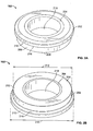
- FIG. 2A is a more detailed view of the example valve seat apparatus illustrated in FIG. 1 .
- FIG. 2B is another detailed view of the example valve seat apparatus illustrated in FIG. 2A .
- FIG. 3A is an enlarged partial cutaway view of the example valve seat apparatus and the fluid regulator of FIGS. 1 , 2A, and 2B .
- FIG. 3B is an enlarged partial cutaway view of the example valve seat apparatus and fluid regulator of FIGS. 1 , 2A , 2B , and 3A .
- fluid regulators modulate the flow of fluid in accordance with a sensed downstream pressure to maintain process system pressures within acceptable and/or constant pressure limits.
- Fluid regulators typically regulate the flow and pressure of process fluid in response to a difference between an outlet fluid pressure (i.e., a force applied to one side of a diaphragm) and a pre-set control force (i.e., a force applied to another side of the diaphragm) to vary the flow through the regulator to achieve a substantially constant outlet pressure.
- Fluid regulators typically include a diaphragm operatively coupled to a valve plug via a diaphragm plate and a valve stem.
- the diaphragm moves in a rectilinear path in response to a difference in force between a force exerted by the pressure of the fluid at the outlet and a pre-set force (e.g., set via a spring). Movement of the diaphragm causes the valve plug to move away from or toward a valve seat to allow or restrict the flow of fluid between the inlet and the outlet of the regulator.
- the valve seat is made of an elastomeric material and is frictionally coupled to the body of the regulator.
- valve seat frictional forces between the elastomeric material of the valve seat and an inner surface the regulator body hold the valve seat in position relative to the regulator body.
- this known configuration may allow the valve seat to shift or move relative to the body due to, for example, reverse pressure conditions (i.e., back pressure conditions) that occur when the outlet pressure is substantially greater than the inlet pressure (e.g., when the valve plug is away from the valve seat).
- back pressure conditions may be due to, for example, temperature fluctuations of the fluid.
- degradation of the elastomeric material of the valve seat may allow the valve seat to shift or move relative to the valve body.
- the elastomeric valve seat may stick or attach to an edge of a valve plug due to, for example, compounds in the elastomeric material leaching out and attaching to the valve plug (e.g., rubber bloom), thereby causing the valve seat to move or shift relative to the body of the regulator when the valve plug moves away from the valve seat.
- compounds in the elastomeric material leaching out and attaching to the valve plug e.g., rubber bloom
- Such shifting or movement of the valve seat relative to the body can cause misalignment between the valve seat and the valve plug, thereby causing unwanted leakage past the valve seat and affecting the performance of the fluid regulator.
- the example valve seat apparatus described herein provide a positive retention to substantially prevent movement of the valve seat apparatus relative to a body of a fluid control device such as, for example, a fluid regulator.
- a valve seat apparatus is coupled (e.g., frictionally coupled, fixedly coupled, etc.) to a regulator body to prevent inadvertent back out of the valve seat apparatus during valve operation.
- an example valve seat apparatus described herein includes an elastomeric ring that frictionally engages or fits within an orifice of a regulator body (or other fluid control device body) to frictionally couple the valve seat apparatus to the regulator body.
- the elastomeric ring is coupled to a metallic ring, which provides rigid support to the resilient elastomeric ring.
- the example elastomeric ring includes an annular lip that frictionally engages (e.g., is disposed within) an annular cavity or groove of the regulator body adjacent the orifice of the regulator body. Also, the annular lip forms a shoulder that engages a shoulder of the body formed by the annular cavity or groove. In this manner, the engagement of the lip with the cavity and the shoulder of the body provides a positive retention and substantially prevents movement of the valve seat apparatus relative to the regulator body.
- Such positive retention is particularly advantageous in applications that experience reverse back pressures between the inlet and the outlet (i.e., outlet pressures that exceed inlet pressures), sticking between the valve plug and the valve seat (e.g., due to rubber bloom) when the valve plug moves away from the valve seat after the valve plug engages the valve seat for an extended period of time, etc., by preventing movement of the valve seat apparatus relative to the body.
- FIG. 1 illustrates a cross-sectional view of an example fluid regulator 100 implemented with an example valve seat apparatus 102 described herein.
- the fluid regulator 100 includes an upper body 104 and a lower body 106 that are coupled together via a plurality of fasteners 108.
- a diaphragm 110 is captured between the upper body 104 and the lower body 106.
- the upper body 104 and a first side 112 of the diaphragm 110 define a first chamber 114.
- a spring 116 is disposed within the upper body 104 between a first spring seat 118 and an adjustable second spring seat 120.
- the first chamber 114 is fluidly coupled to, for example, the atmosphere, via an aperture 122.
- the first spring seat 118 is coupled to a diaphragm plate 124 that supports the diaphragm 110.
- a spring adjuster 126 e.g., a screw engages the second spring seat 120 to enable adjustment of the length of the spring 116 (e.g., compress or decompress the spring 116) and, thus, adjustment (e.g., to increase or decrease) of the amount of a pre-set force or load that the spring 116 exerts on the first side 112 of the diaphragm 110.
- the lower body 106 and a second side 128 of the diaphragm 110 at least partially define a second chamber 130, an inlet 132, and an outlet 134.
- the second chamber 130 is fluidly coupled to the outlet 134 via a channel 136.
- the valve seat apparatus 102 is disposed within the lower body 106 and defines an orifice 138 between the inlet 132 and the outlet 134.
- a valve plug 140 is operatively coupled to the diaphragm 110 via a valve stem 142 and the diaphragm plate 124.
- a second spring 144 is disposed within a cavity 146 of a valve plug retainer 148 to bias the valve plug 140 toward the valve seat apparatus 102.
- the valve plug 140 engages the valve seat apparatus 102 to provide a tight seal to prevent fluid flow between the inlet 132 and the outlet 134.
- the spring rate of the second spring 144 is typically substantially smaller relative to the spring rate of the spring 116.
- the fluid regulator 100 includes an internal relief valve 150 coupled to the diaphragm 110 via the diaphragm plate 124.
- the relief valve 150 includes an aperture 152 that fluidly couples the first chamber 114 and the second chamber 130.
- a second end 154 of the valve stem 142 includes a soft or compliant seat 156 that engages the aperture 152 of the relief valve 150 to prevent (e.g., block) the flow of fluid between the first and second chambers 114 and 130, respectively.
- the fluid regulator 100 may include a coupling seat (i.e., a non-venting seat) instead of the internal relief valve 150 to operatively couple the diaphragm 110 and the valve plug 140.
- the valve stem 142 may be fixedly coupled to the diaphragm plate 124 (e.g., via fasteners).
- the inlet 132 is in fluid communication with, for example, an upstream fluid distribution source that provides fluid having a relatively high pressure.
- the outlet 134 is in fluid communication with a downstream demand source, pressure regulator, or any other custody point that demands process fluid at a desired (e.g., a lower) pressure.
- the fluid regulator 100 typically regulates the upstream pressure of the fluid at the inlet 132 to provide or develop a desired pressure at the outlet 134.
- the spring 116 exerts a force on the first side 112 of the diaphragm 110 which, in turn, positions the valve plug 140 relative to the valve seat apparatus 102 to restrict the flow of the process fluid between the inlet 132 and the outlet 134.
- the outlet or desired pressure is dependent upon the amount of pre-set force exerted by the spring 116 to position the diaphragm 110 and, thus, the valve plug 140 relative to the valve seat apparatus 102.
- the desired pressure set point may be configured by adjusting the force exerted by the spring 116 on the first side 112 of the diaphragm 110 via the spring adjuster 126.
- the pressure of the fluid at the outlet 134 decreases.
- the second chamber 130 senses the decreasing pressure of the process fluid at the outlet 134 via the channel 136.
- the spring 116 causes the diaphragm 110 to move toward the second chamber 130.
- valve plug 140 moves away from the valve seat apparatus 102 to allow fluid to flow through the orifice 138 between the inlet 132 and the outlet 134 (e.g., an open position), thereby causing the pressure at the outlet 134 to increase.
- the pressure of the process fluid at the outlet 134 increases.
- the increasing fluid pressure at the outlet 134 is registered in the second chamber 130 via the channel 136 and exerts a force on the second side 128 of the diaphragm 110.
- the pressure of the fluid in the second chamber 130 exerts a force on the second side 128 of the diaphragm 110 that equals or exceeds the pre-set force exerted by the spring 116 on the first side 112 of the diaphragm 110
- the diaphragm 110 moves toward the first chamber 114 (e.g., an upward direction against the force exerted by the spring 116 in the orientation of FIG. 1 ).
- the diaphragm 110 moves toward the first chamber 114, the diaphragm 110 causes the valve plug 140 to move toward the valve seat apparatus 102 to restrict the flow of fluid through the orifice 138.
- the second spring 144 biases the valve plug 140 toward the valve seat apparatus 102 to sealingly engage the valve seat apparatus 102 (e.g., in a closed position) to substantially prevent fluid flow through the orifice 138 between the inlet 132 and the outlet 134 and, thus, reduce supply of the pressure to the downstream source (i.e., a lock-up condition).
- a lock-up condition of the fluid regulator 100 occurs when the valve plug 140 sealingly engages the valve seat apparatus 102 to provide a tight seal and prevent fluid flow between the inlet 132 and the outlet 134.
- the soft seat 156 engages the aperture 152 of the relief valve 150 to prevent unwanted leakage of fluid between the first and second chambers 114 and 130.
- the valve plug 140 engages the valve seat apparatus 102 to prevent the flow of fluid between the inlet 132 and the outlet 134.
- the pressure of the fluid at the outlet 134 increases when the downstream demand decreases (e.g., the downstream source is shut-off) and the valve plug 140 fails to sealingly engage the valve seat apparatus 102 (i.e., the regulator 100 fails to lock-up) due to, for example, grit, pipe scale, etc.
- the increase in pressure of the fluid at the outlet 134 exerts a force on the second side 128 of the diaphragm 110 that causes the diaphragm 110 and the diaphragm plate 124 to move toward the first chamber 114 (i.e., to compress the spring 116 in an upward direction in the orientation of FIG. 1 ).
- the relief valve 150 which is coupled to the diaphragm 110 via the diaphragm plate 124, moves away from the soft seat 156. Movement of the diaphragm 110 toward the first chamber 114 causes the internal relief valve 150 to move away from the soft seat 156 to fluidly couple the second chamber 130 and the first chamber 114 to bleed or vent the pressure to, for example, the atmosphere via the aperture 122.
- the example valve seat apparatus 102 described herein advantageously prevents the valve seat apparatus 102 from inadvertently backing out of the lower body 106 (i.e., moving away from the body 106) due to back pressure conditions.
- an outlet pressure that is greater than the inlet pressure does not cause the valve seat apparatus 102 to shift or move relative to the lower body 106 (e.g., the orifice 138).
- the example seat apparatus 102 described herein advantageously prevents the valve seat apparatus 102 from inadvertently shifting or moving relative to the lower body 106 due to, for example, the valve plug 140 sticking or attaching to the valve seat apparatus 102 (e.g., due to rubber bloom) when the valve plug 140 moves away from the valve seat apparatus 102 after the valve plug 140 engages the valve seat apparatus 102 for an extended period of time. As noted above, preventing such movement prevents misalignment between the valve plug 140 and the valve seat apparatus 102, thereby improving regulator performance.
- FIG. 2A is a more detailed view of the example valve seat apparatus 102 illustrated in FIG. 1 .
- FIG. 2B is another detailed view of the example valve seat apparatus 102 illustrated in FIG. 2A .
- the example valve seat apparatus 102 includes a sealing member 202 coupled to a rigid support member 204.
- the sealing member 202 is a substantially resilient elastomeric ring-shaped member or ring and the rigid support member 204 is a substantially rigid metallic ring-shaped member or ring.
- the elastomeric ring 202 is coupled to the metallic ring 204 and provides sealing surfaces 206 and 208.
- the elastomeric ring 202 includes at least one protruding member or annular lip 210.
- the elastomeric ring 202 has a first outer diameter 212 and a second outer diameter 214 that is larger than the first outer diameter 212 to form the lip 210.
- the lip 210 also forms a shoulder 216 between the diameters 212 and 214.
- the elastomeric ring 202 may include a plurality of annular lips.
- the elastomeric ring 202 may be made of, for example, rubber, nitrile, fluoroelastomer (FKM), Neoprene, or any other suitable elastomeric and/or resilient materials.
- the elastomeric ring 202 surrounds the metallic ring 204 so that the metallic ring 204 supports the elastomeric ring 202.
- the metallic ring 204 has an aperture 218 that provides a fluid flow passageway when the valve seat apparatus 102 is disposed within the lower body 106 of the fluid regulator 100.
- the metallic ring 204 is made of stainless steel and manufactured via machining.
- the ring 204 may be made of brass, carbon steel, plastic, or any other suitable rigid material(s).
- the metallic ring 204 may be manufactured via molding and/or any other suitable manufacturing process(es).
- the elastomeric ring 202 is coupled to the metallic ring 204 via molding (e.g., over molding).
- the elastomeric ring 202 is molded over the metallic ring 204 to form the valve seat apparatus 102.
- the elastomeric ring 202 may be assembled or press fit to the metallic ring 204 to form the valve seat apparatus 102.
- the metallic ring 204 includes an annular protruding edge 302 ( FIG. 3B ) protruding from an outer surface 304 ( FIG. 3B ) of the metallic ring 204.
- the protruding edge 302 may be formed via, for example, machining.
- the protruding edge 302 has a rectangular cross-sectional shape.
- the protruding edge 302 may have a T-shape cross-sectional shape, an arcuate cross-sectional shape, or any other suitable cross-sectional shape.
- an inner surface 306 ( FIG. 3B ) of the elastomeric ring 202 has (e.g., forms) an annular groove 308 to receive the protruding edge 302 when the elastomeric ring 202 is coupled (e.g., over molded) to the metallic ring 204.
- the elastomeric ring 202 may be coupled or bonded to the metallic ring 204 via chemical fasteners (e.g., adhesives) or any other suitable fastening mechanism(s).
- a portion 307 of the outer surface 304 of the metallic ring 204 is tapered.
- the outer surface 304 of the metallic ring 204 may include any other suitable shape.
- FIG. 3A illustrates an enlarged partial cutaway view of the example valve seat apparatus 102 and the fluid regulator 100 of FIGS. 1 , 2A , and 2B .
- FIG. 3B illustrates an enlarged partial cutaway view of the example valve seat apparatus 102 and fluid regulator 100 shown in FIGS. 1 , 2A , 2B , and 3A .
- the valve seat apparatus 102 is disposed within (e.g., inserted into) the lower body 106 of the fluid regulator 100 to encompass a flow path between the inlet 132 and the outlet 134. More specifically, the valve seat apparatus 102 is frictionally fit or coupled to the orifice 138 of the lower body 106.
- the lower body 106 includes an undercut or cavity 310 that forms a shoulder 312.
- the valve seat apparatus 102 is press fit within the orifice 138 (e.g., via a tool) so that the lip 210 engages (e.g., is inserted into) the cavity 310 of the lower body 106. In this manner, the lip 210 is disposed within the cavity 310 so that the shoulder 216 of the elastomeric ring 202 engages the shoulder 312 of the lower body 106.
- the valve seat apparatus 102 provides a positive retention to prevent the valve seat apparatus 102 from moving or shifting relative to the lower body 106.
- the shoulder 312 may have a tapered edge, a substantially right-angled edge, a chamfered edge, or any other suitable edge.
- the frictional forces between the sealing surface 208 and the lip 210 of the elastomeric ring 202 and respective surfaces 314 and 316 of the lower body 106 frictionally couple the valve seat apparatus 102 to the lower body 106 when the valve seat apparatus 102 is disposed within the lower body 106.
- the metallic ring 204 provides support to the elastomeric ring 202 and exerts radial reactive forces in a direction toward the surfaces 314 and 316 of the lower body 106 to prevent the elastomeric ring 202 from radially collapsing (e.g., folding) toward the orifice 138 when disposed within the lower body 106. As most clearly shown in FIG.
- the lip 210 is compressed between the surface 314 and the outer surface 304 of the metallic ring 204 when disposed in the cavity 310 of the lower body 106.
- the sealing surface 208 is compressed between the surface 316 of the lower body 106 and the outer surface 304 of the metallic ring 204.
- valve plug 140 sealingly engages the sealing surface 206 of the elastomeric ring 202 to prevent fluid flow between the inlet 132 and the outlet 134.
- the valve plug 140 has a knife-edge cross-sectional shape 318 that engages the sealing surface 206.
- the valve plug 140 may have any other suitable cross-sectional shape.
- the lip 210 provides a positive retention to prevent the valve seat apparatus 102 from moving relative to the valve plug 140 iF the valve plug 140 sticks or attaches to the sealing surface 206.
- the valve plug 140 may engage the sealing surface 206 of the valve seat apparatus 102 for a substantial period of time (e.g., during a lock-up condition of the regulator 100).
- the knife-edge 318 of the valve plug 140 may stick or attach to the sealing surface 206 due to, for example, compounds of the elastomeric ring 202 leaching thereby causing the valve plug 140 to attach to the sealing surface 206 (e.g., due to rubber bloom).
- the lip 210 provides a positive retention and prevents the valve seat apparatus 102 from moving or shifting relative to the lower body 106.
- the example valve seat apparatus 102 is not limited for use with the example fluid regulator 100 of FIGS. 1 , 2A , 2B , 3A, and 3B .
- the valve seat apparatus 102 may be implemented with other fluid regulators, control valves (e.g., linear valves, rotary valves, etc.), and/or any other suitable fluid control devices.
Description
- The present disclosure relates generally to fluid control devices and, more particularly, to valve seat apparatus having positive retention for use with fluid control devices.
- Fluid control devices, such as fluid regulators and control valves, are commonly distributed throughout process control systems to control fluid flow rates and/or pressures of various fluids (e.g., liquids, gasses, etc.). For example, fluid regulators are typically used to regulate the pressure of a fluid to a lower and/or substantially constant value. Specifically, a fluid regulator has an inlet that typically receives a supply fluid at a relatively high pressure and provides a relatively lower and/or substantially constant pressure at an outlet. As the high pressure process fluid travels through the process control system, the regulator reduces the pressure of the process fluid at one or more points to supply a process fluid having a lower or reduced pressure to a sub-system or other custody transfer points. For example, a regulator associated with a piece of equipment (e.g., a boiler) may receive a fluid (e.g., gas) having a relatively high and somewhat variable pressure from a fluid distribution source and may regulate the fluid to have a lower, substantially constant pressure suitable for safe, efficient use by the equipment.
- A regulator typically reduces inlet pressure to a lower outlet pressure by restricting fluid flow through an orifice to match the fluctuating downstream demand. To restrict fluid flow between an inlet and an outlet, a regulator typically employs a valve plug to engage a valve seat disposed within the orifice of the regulator body. Some known fluid regulators use a valve seat made from an elastomeric material to provide a tight seal between the valve seat and a valve plug. In such known regulators, the valve seat is typically disposed within the orifice so that the frictional forces between the elastomeric valve seat and the body of the regulator maintain the valve seat within the body of the regulator. However, this known frictional coupling of the valve seat to the body of the regulator may allow the valve seat to shift or move relative the body due to, for example, reverse pressure (i.e., back pressure) conditions, degradation of the elastomeric material, sticking between the valve plug and the valve seat (e.g., due to rubber bloom) when the valve plug moves away from the valve seat, etc. Such shifting or movement of the valve seat relative to the body can cause misalignment between the valve seat and the valve plug, thereby causing unwanted leakage of fluid past the valve seat and affecting the performance of the fluid regulator. Prior art fluid regulators as described are known from
GB 2 114 269
US 2 979 067 orUS 2 060 748 , for example. - The above problems are overcome by the solution provided by the subject matter of claim 1.
- In one example, a valve seat apparatus having a positive retention for use with a fluid control device includes a metallic ring and an elastomeric ring coupled to the metallic ring and having a sealing surface to sealingly engage a flow control member of the fluid control device. At least a portion of an outer surface of the elastomeric ring includes an annular lip to sealingly engage an annular recess of a body of the fluid control device.
- In another example, a valve seat apparatus having a positive retention for use with a fluid regulator includes a substantially rigid support member coupled to a substantially resilient sealing member. An inner surface of the sealing member is coupled to the outer surface of the support member and at least a portion of an outer surface of the sealing member has a first outer diameter and a second outer diameter larger than the first outer diameter to form at least one protruding member to retain the valve seat apparatus in a body of the fluid regulator.
- In yet another example, a fluid regulator includes a body having a shoulder formed by an annular cavity in the body between an inlet and an outlet and a valve seat disposed within the body. The valve seat includes a first ring-shaped member and a second ring-shaped member coupled to the first ring-shaped member to provide a sealing surface to sealingly engage a movable valve plug of the regulator. The second ring-shaped member has an outer lip portion frictionally engaged in the annular cavity so that the lip portion engages the shoulder of the body to retain the valve seat in the body.
-
FIG. I illustrates a cross-sectional view of a fluid regulator implemented with an example valve seat apparatus described herein. -
FIG. 2A is a more detailed view of the example valve seat apparatus illustrated inFIG. 1 . -
FIG. 2B is another detailed view of the example valve seat apparatus illustrated inFIG. 2A . -
FIG. 3A is an enlarged partial cutaway view of the example valve seat apparatus and the fluid regulator ofFIGS. 1 ,2A, and 2B . -
FIG. 3B is an enlarged partial cutaway view of the example valve seat apparatus and fluid regulator ofFIGS. 1 ,2A ,2B , and3A . - In general, fluid regulators modulate the flow of fluid in accordance with a sensed downstream pressure to maintain process system pressures within acceptable and/or constant pressure limits. Fluid regulators typically regulate the flow and pressure of process fluid in response to a difference between an outlet fluid pressure (i.e., a force applied to one side of a diaphragm) and a pre-set control force (i.e., a force applied to another side of the diaphragm) to vary the flow through the regulator to achieve a substantially constant outlet pressure.
- Fluid regulators typically include a diaphragm operatively coupled to a valve plug via a diaphragm plate and a valve stem. The diaphragm moves in a rectilinear path in response to a difference in force between a force exerted by the pressure of the fluid at the outlet and a pre-set force (e.g., set via a spring). Movement of the diaphragm causes the valve plug to move away from or toward a valve seat to allow or restrict the flow of fluid between the inlet and the outlet of the regulator. In some known regulators, the valve seat is made of an elastomeric material and is frictionally coupled to the body of the regulator. In particular, frictional forces between the elastomeric material of the valve seat and an inner surface the regulator body hold the valve seat in position relative to the regulator body. However, this known configuration may allow the valve seat to shift or move relative to the body due to, for example, reverse pressure conditions (i.e., back pressure conditions) that occur when the outlet pressure is substantially greater than the inlet pressure (e.g., when the valve plug is away from the valve seat). Such back pressure conditions may be due to, for example, temperature fluctuations of the fluid. Additionally or alternatively, degradation of the elastomeric material of the valve seat may allow the valve seat to shift or move relative to the valve body. Additionally or alternatively, when the valve plug engages the valve seat for an extended period of time, the elastomeric valve seat may stick or attach to an edge of a valve plug due to, for example, compounds in the elastomeric material leaching out and attaching to the valve plug (e.g., rubber bloom), thereby causing the valve seat to move or shift relative to the body of the regulator when the valve plug moves away from the valve seat. Such shifting or movement of the valve seat relative to the body can cause misalignment between the valve seat and the valve plug, thereby causing unwanted leakage past the valve seat and affecting the performance of the fluid regulator.
- The example valve seat apparatus described herein provide a positive retention to substantially prevent movement of the valve seat apparatus relative to a body of a fluid control device such as, for example, a fluid regulator. In one example described herein, a valve seat apparatus is coupled (e.g., frictionally coupled, fixedly coupled, etc.) to a regulator body to prevent inadvertent back out of the valve seat apparatus during valve operation. In particular, an example valve seat apparatus described herein includes an elastomeric ring that frictionally engages or fits within an orifice of a regulator body (or other fluid control device body) to frictionally couple the valve seat apparatus to the regulator body. The elastomeric ring is coupled to a metallic ring, which provides rigid support to the resilient elastomeric ring. Additionally, unlike known valve seats, the example elastomeric ring includes an annular lip that frictionally engages (e.g., is disposed within) an annular cavity or groove of the regulator body adjacent the orifice of the regulator body. Also, the annular lip forms a shoulder that engages a shoulder of the body formed by the annular cavity or groove. In this manner, the engagement of the lip with the cavity and the shoulder of the body provides a positive retention and substantially prevents movement of the valve seat apparatus relative to the regulator body. Such positive retention is particularly advantageous in applications that experience reverse back pressures between the inlet and the outlet (i.e., outlet pressures that exceed inlet pressures), sticking between the valve plug and the valve seat (e.g., due to rubber bloom) when the valve plug moves away from the valve seat after the valve plug engages the valve seat for an extended period of time, etc., by preventing movement of the valve seat apparatus relative to the body.
-
FIG. 1 illustrates a cross-sectional view of anexample fluid regulator 100 implemented with an examplevalve seat apparatus 102 described herein. In this example, thefluid regulator 100 includes anupper body 104 and alower body 106 that are coupled together via a plurality offasteners 108. Adiaphragm 110 is captured between theupper body 104 and thelower body 106. Theupper body 104 and afirst side 112 of thediaphragm 110 define afirst chamber 114. Aspring 116 is disposed within theupper body 104 between afirst spring seat 118 and an adjustablesecond spring seat 120. In this example, thefirst chamber 114 is fluidly coupled to, for example, the atmosphere, via anaperture 122. - The
first spring seat 118 is coupled to adiaphragm plate 124 that supports thediaphragm 110. A spring adjuster 126 (e.g., a screw) engages thesecond spring seat 120 to enable adjustment of the length of the spring 116 (e.g., compress or decompress the spring 116) and, thus, adjustment (e.g., to increase or decrease) of the amount of a pre-set force or load that thespring 116 exerts on thefirst side 112 of thediaphragm 110. - The
lower body 106 and asecond side 128 of thediaphragm 110 at least partially define asecond chamber 130, aninlet 132, and anoutlet 134. Thesecond chamber 130 is fluidly coupled to theoutlet 134 via achannel 136. Thevalve seat apparatus 102 is disposed within thelower body 106 and defines anorifice 138 between theinlet 132 and theoutlet 134. Avalve plug 140 is operatively coupled to thediaphragm 110 via avalve stem 142 and thediaphragm plate 124. Asecond spring 144 is disposed within acavity 146 of avalve plug retainer 148 to bias thevalve plug 140 toward thevalve seat apparatus 102. In the illustrated example, thevalve plug 140 engages thevalve seat apparatus 102 to provide a tight seal to prevent fluid flow between theinlet 132 and theoutlet 134. The spring rate of thesecond spring 144 is typically substantially smaller relative to the spring rate of thespring 116. - In this example, the
fluid regulator 100 includes aninternal relief valve 150 coupled to thediaphragm 110 via thediaphragm plate 124. Therelief valve 150 includes anaperture 152 that fluidly couples thefirst chamber 114 and thesecond chamber 130. Asecond end 154 of thevalve stem 142 includes a soft orcompliant seat 156 that engages theaperture 152 of therelief valve 150 to prevent (e.g., block) the flow of fluid between the first andsecond chambers fluid regulator 100 may include a coupling seat (i.e., a non-venting seat) instead of theinternal relief valve 150 to operatively couple thediaphragm 110 and thevalve plug 140. In yet other examples, thevalve stem 142 may be fixedly coupled to the diaphragm plate 124 (e.g., via fasteners). - In operation, the
inlet 132 is in fluid communication with, for example, an upstream fluid distribution source that provides fluid having a relatively high pressure. Theoutlet 134 is in fluid communication with a downstream demand source, pressure regulator, or any other custody point that demands process fluid at a desired (e.g., a lower) pressure. - The
fluid regulator 100 typically regulates the upstream pressure of the fluid at theinlet 132 to provide or develop a desired pressure at theoutlet 134. To achieve a desired outlet pressure, thespring 116 exerts a force on thefirst side 112 of thediaphragm 110 which, in turn, positions thevalve plug 140 relative to thevalve seat apparatus 102 to restrict the flow of the process fluid between theinlet 132 and theoutlet 134. Thus, the outlet or desired pressure is dependent upon the amount of pre-set force exerted by thespring 116 to position thediaphragm 110 and, thus, thevalve plug 140 relative to thevalve seat apparatus 102. The desired pressure set point may be configured by adjusting the force exerted by thespring 116 on thefirst side 112 of thediaphragm 110 via thespring adjuster 126. - When the downstream demand increases, the pressure of the fluid at the
outlet 134 decreases. Thesecond chamber 130 senses the decreasing pressure of the process fluid at theoutlet 134 via thechannel 136. When the force exerted on thesecond side 128 of thediaphragm 110 by the pressure of the fluid in thesecond chamber 130 decreases below the pre-set force exerted by thespring 116 on thefirst side 112 of thediaphragm 110, thespring 116 causes thediaphragm 110 to move toward thesecond chamber 130. When thediaphragm 110 moves toward thesecond chamber 130, thevalve plug 140 moves away from thevalve seat apparatus 102 to allow fluid to flow through theorifice 138 between theinlet 132 and the outlet 134 (e.g., an open position), thereby causing the pressure at theoutlet 134 to increase. - Conversely, as the outlet or downstream demand decreases or is shut-off, the pressure of the process fluid at the
outlet 134 increases. As noted above, the increasing fluid pressure at theoutlet 134 is registered in thesecond chamber 130 via thechannel 136 and exerts a force on thesecond side 128 of thediaphragm 110. When the pressure of the fluid in thesecond chamber 130 exerts a force on thesecond side 128 of thediaphragm 110 that equals or exceeds the pre-set force exerted by thespring 116 on thefirst side 112 of thediaphragm 110, thediaphragm 110 moves toward the first chamber 114 (e.g., an upward direction against the force exerted by thespring 116 in the orientation ofFIG. 1 ). When thediaphragm 110 moves toward thefirst chamber 114, thediaphragm 110 causes thevalve plug 140 to move toward thevalve seat apparatus 102 to restrict the flow of fluid through theorifice 138. Thesecond spring 144 biases thevalve plug 140 toward thevalve seat apparatus 102 to sealingly engage the valve seat apparatus 102 (e.g., in a closed position) to substantially prevent fluid flow through theorifice 138 between theinlet 132 and theoutlet 134 and, thus, reduce supply of the pressure to the downstream source (i.e., a lock-up condition). A lock-up condition of thefluid regulator 100 occurs when thevalve plug 140 sealingly engages thevalve seat apparatus 102 to provide a tight seal and prevent fluid flow between theinlet 132 and theoutlet 134. - During normal operation (e.g., prior to lock-up), the
soft seat 156 engages theaperture 152 of therelief valve 150 to prevent unwanted leakage of fluid between the first andsecond chambers valve plug 140 engages thevalve seat apparatus 102 to prevent the flow of fluid between theinlet 132 and theoutlet 134. - However, in some instances, the pressure of the fluid at the
outlet 134 increases when the downstream demand decreases (e.g., the downstream source is shut-off) and thevalve plug 140 fails to sealingly engage the valve seat apparatus 102 (i.e., theregulator 100 fails to lock-up) due to, for example, grit, pipe scale, etc. The increase in pressure of the fluid at theoutlet 134 exerts a force on thesecond side 128 of thediaphragm 110 that causes thediaphragm 110 and thediaphragm plate 124 to move toward the first chamber 114 (i.e., to compress thespring 116 in an upward direction in the orientation ofFIG. 1 ). As a result, therelief valve 150, which is coupled to thediaphragm 110 via thediaphragm plate 124, moves away from thesoft seat 156. Movement of thediaphragm 110 toward thefirst chamber 114 causes theinternal relief valve 150 to move away from thesoft seat 156 to fluidly couple thesecond chamber 130 and thefirst chamber 114 to bleed or vent the pressure to, for example, the atmosphere via theaperture 122. - The example
valve seat apparatus 102 described herein advantageously prevents thevalve seat apparatus 102 from inadvertently backing out of the lower body 106 (i.e., moving away from the body 106) due to back pressure conditions. Unlike some known valve seats, for example, an outlet pressure that is greater than the inlet pressure does not cause thevalve seat apparatus 102 to shift or move relative to the lower body 106 (e.g., the orifice 138). Additionally or alternatively, theexample seat apparatus 102 described herein advantageously prevents thevalve seat apparatus 102 from inadvertently shifting or moving relative to thelower body 106 due to, for example, thevalve plug 140 sticking or attaching to the valve seat apparatus 102 (e.g., due to rubber bloom) when thevalve plug 140 moves away from thevalve seat apparatus 102 after thevalve plug 140 engages thevalve seat apparatus 102 for an extended period of time. As noted above, preventing such movement prevents misalignment between thevalve plug 140 and thevalve seat apparatus 102, thereby improving regulator performance. -
FIG. 2A is a more detailed view of the examplevalve seat apparatus 102 illustrated inFIG. 1 .FIG. 2B is another detailed view of the examplevalve seat apparatus 102 illustrated inFIG. 2A . Referring toFIGS. 2A and 2B , the examplevalve seat apparatus 102 includes a sealingmember 202 coupled to arigid support member 204. In this example, the sealingmember 202 is a substantially resilient elastomeric ring-shaped member or ring and therigid support member 204 is a substantially rigid metallic ring-shaped member or ring. Theelastomeric ring 202 is coupled to themetallic ring 204 and provides sealingsurfaces - In this example, at least a portion of the
elastomeric ring 202 includes at least one protruding member orannular lip 210. Theelastomeric ring 202 has a firstouter diameter 212 and a secondouter diameter 214 that is larger than the firstouter diameter 212 to form thelip 210. Thelip 210 also forms ashoulder 216 between thediameters elastomeric ring 202 may include a plurality of annular lips. Theelastomeric ring 202 may be made of, for example, rubber, nitrile, fluoroelastomer (FKM), Neoprene, or any other suitable elastomeric and/or resilient materials. - The
elastomeric ring 202 surrounds themetallic ring 204 so that themetallic ring 204 supports theelastomeric ring 202. Themetallic ring 204 has anaperture 218 that provides a fluid flow passageway when thevalve seat apparatus 102 is disposed within thelower body 106 of thefluid regulator 100. In this example, themetallic ring 204 is made of stainless steel and manufactured via machining. However, in other examples, thering 204 may be made of brass, carbon steel, plastic, or any other suitable rigid material(s). In yet other examples, themetallic ring 204 may be manufactured via molding and/or any other suitable manufacturing process(es). - In this example, the
elastomeric ring 202 is coupled to themetallic ring 204 via molding (e.g., over molding). Theelastomeric ring 202 is molded over themetallic ring 204 to form thevalve seat apparatus 102. In other examples, theelastomeric ring 202 may be assembled or press fit to themetallic ring 204 to form thevalve seat apparatus 102. To facilitate coupling theelastomeric ring 202 to themetallic ring 204 via, for example, molding, themetallic ring 204 includes an annular protruding edge 302 (FIG. 3B ) protruding from an outer surface 304 (FIG. 3B ) of themetallic ring 204. The protrudingedge 302 may be formed via, for example, machining. In this example, the protrudingedge 302 has a rectangular cross-sectional shape. However, in other examples, the protrudingedge 302 may have a T-shape cross-sectional shape, an arcuate cross-sectional shape, or any other suitable cross-sectional shape. Likewise, an inner surface 306 (FIG. 3B ) of theelastomeric ring 202 has (e.g., forms) anannular groove 308 to receive the protrudingedge 302 when theelastomeric ring 202 is coupled (e.g., over molded) to themetallic ring 204. In other examples, theelastomeric ring 202 may be coupled or bonded to themetallic ring 204 via chemical fasteners (e.g., adhesives) or any other suitable fastening mechanism(s). In this example, aportion 307 of theouter surface 304 of themetallic ring 204 is tapered. In other examples, theouter surface 304 of themetallic ring 204 may include any other suitable shape. -
FIG. 3A illustrates an enlarged partial cutaway view of the examplevalve seat apparatus 102 and thefluid regulator 100 ofFIGS. 1 ,2A , and2B .FIG. 3B illustrates an enlarged partial cutaway view of the examplevalve seat apparatus 102 andfluid regulator 100 shown inFIGS. 1 ,2A ,2B , and3A . Referring toFIGS. 3A and 3B , thevalve seat apparatus 102 is disposed within (e.g., inserted into) thelower body 106 of thefluid regulator 100 to encompass a flow path between theinlet 132 and theoutlet 134. More specifically, thevalve seat apparatus 102 is frictionally fit or coupled to theorifice 138 of thelower body 106. Thelower body 106 includes an undercut orcavity 310 that forms ashoulder 312. Thevalve seat apparatus 102 is press fit within the orifice 138 (e.g., via a tool) so that thelip 210 engages (e.g., is inserted into) thecavity 310 of thelower body 106. In this manner, thelip 210 is disposed within thecavity 310 so that theshoulder 216 of theelastomeric ring 202 engages theshoulder 312 of thelower body 106. As a result, thevalve seat apparatus 102 provides a positive retention to prevent thevalve seat apparatus 102 from moving or shifting relative to thelower body 106. Theshoulder 312 may have a tapered edge, a substantially right-angled edge, a chamfered edge, or any other suitable edge. - Additionally, the frictional forces between the sealing
surface 208 and thelip 210 of theelastomeric ring 202 andrespective surfaces lower body 106 frictionally couple thevalve seat apparatus 102 to thelower body 106 when thevalve seat apparatus 102 is disposed within thelower body 106. Themetallic ring 204 provides support to theelastomeric ring 202 and exerts radial reactive forces in a direction toward thesurfaces lower body 106 to prevent theelastomeric ring 202 from radially collapsing (e.g., folding) toward theorifice 138 when disposed within thelower body 106. As most clearly shown inFIG. 3B , thelip 210 is compressed between thesurface 314 and theouter surface 304 of themetallic ring 204 when disposed in thecavity 310 of thelower body 106. Similarly, the sealingsurface 208 is compressed between thesurface 316 of thelower body 106 and theouter surface 304 of themetallic ring 204. - In operation, the
valve plug 140 sealingly engages the sealingsurface 206 of theelastomeric ring 202 to prevent fluid flow between theinlet 132 and theoutlet 134. In this example, thevalve plug 140 has a knife-edgecross-sectional shape 318 that engages the sealingsurface 206. However, in other examples, thevalve plug 140 may have any other suitable cross-sectional shape. When thevalve plug 140 moves away from the sealingsurface 206, fluid flows between theinlet 132 and theoutlet 134 through theaperture 218 of themetallic ring 204. If thevalve seat apparatus 102 is exposed to high pressures and/or back pressure conditions, thelip 210 provides a positive retention and prevents thevalve seat apparatus 102 from moving or shifting relative to thelower body 106, thereby improving regulator performance. - Additionally or alternatively, in operation, the
lip 210 provides a positive retention to prevent thevalve seat apparatus 102 from moving relative to thevalve plug 140 iF thevalve plug 140 sticks or attaches to the sealingsurface 206. For example, in operation, thevalve plug 140 may engage the sealingsurface 206 of thevalve seat apparatus 102 for a substantial period of time (e.g., during a lock-up condition of the regulator 100). As a result, the knife-edge 318 of thevalve plug 140 may stick or attach to the sealingsurface 206 due to, for example, compounds of theelastomeric ring 202 leaching thereby causing thevalve plug 140 to attach to the sealing surface 206 (e.g., due to rubber bloom). When thevalve plug 140 moves away from thevalve seat apparatus 102 to the open position, thelip 210 provides a positive retention and prevents thevalve seat apparatus 102 from moving or shifting relative to thelower body 106. - The example
valve seat apparatus 102 is not limited for use with theexample fluid regulator 100 ofFIGS. 1 ,2A ,2B ,3A, and 3B . In other examples, thevalve seat apparatus 102 may be implemented with other fluid regulators, control valves (e.g., linear valves, rotary valves, etc.), and/or any other suitable fluid control devices. - Although certain example apparatus have been described herein, the scope of coverage of this patent is not limited thereto. On the contrary, this patent covers all apparatus and articles of manufacture fairly falling within the scope of the appended claims either literally or under the doctrine of equivalents.
Claims (11)
- A valve seat apparatus (102) having a positive retention for use with a fluid control device, comprising a rigid support ring (204) defining an aperture (218) that provides a fluid flow passageway and an outer annular surface (304) spaced radially outwardly from the aperture; and an elastomeric ring surrounding the outer annular surface of the rigid support ring and coupled to the metallic ring, the elastomeric ring having a sealing surface (206) to sealingly engage a flow control member of the fluid control device, wherein at least a portion of an outer surface of the elastomeric ring includes an annular lip (210) to sealingly engage an annular recess (314) of a body of the fluid control device;
characterized in that an annular protruding edge (302) protrudes from the outer annular surface disposed between a first portion (304) of the outer annular surface and a second portion (307) of the outer annular surface, and an inner surface of the elastomeric ring comprises an annular groove (308) that receives the annular protruding edge (302) of the rigid support ring. - A valve seat apparatus as defined in claim 1, wherein the inner surface of the elastomeric ring is coupled to the outer annular surface of the rigid support ring.
- A valve seat apparatus as defined in claim 2, wherein the elastomeric ring is molded over the rigid support ring.
- A valve seat apparatus as defined in claim 1, wherein the second portion (307) is tapered.
- A valve seat apparatus as defined in claim 1, wherein the sealing surface is to engage a valve plug (140) of the fluid control device.
- A valve seat apparatus as defined in claim 1, wherein the elastomeric ring is frictionally coupled to the body of the fluid control device.
- The valve seat apparatus as defined in claim 1, wherein the sealing surface (206) is orthogonal to an axis through the aperture (318) of the rigid support ring (204).
- The valve seat apparatus as defined in claim 7, wherein the sealing surface is coplanar with an end surface of the rigid support ring.
- The valve seat apparatus as defined in claim 1, wherein the elastomeric ring completely surrounds and covers the outer radial surface of the rigid support ring.
- The valve seat apparatus as defined in claim 1, wherein the rigid support ring (204) is made of metal or plastic.
- The valve seat apparatus as defined in claim 1, wherein the annular protruding edge has one of a rectangular cross-sectional shape, a T- cross-sectional shape, and an arcuate cross-sectional shape.
Applications Claiming Priority (2)
| Application Number | Priority Date | Filing Date | Title |
|---|---|---|---|
| US12/327,161 US8864106B2 (en) | 2008-12-03 | 2008-12-03 | Valve seat apparatus having positive retention for use with fluid control devices |
| PCT/US2009/064043 WO2010065254A1 (en) | 2008-12-03 | 2009-11-11 | Valve seat apparatus having positive retention for use with fluid control devices |
Publications (2)
| Publication Number | Publication Date |
|---|---|
| EP2370871A1 EP2370871A1 (en) | 2011-10-05 |
| EP2370871B1 true EP2370871B1 (en) | 2013-06-26 |
Family
ID=41572494
Family Applications (1)
| Application Number | Title | Priority Date | Filing Date |
|---|---|---|---|
| EP20090759836 Active EP2370871B1 (en) | 2008-12-03 | 2009-11-11 | Valve seat apparatus having positive retention for use with fluid control devices |
Country Status (7)
| Country | Link |
|---|---|
| US (1) | US8864106B2 (en) |
| EP (1) | EP2370871B1 (en) |
| JP (1) | JP5738769B2 (en) |
| CN (1) | CN102239456B (en) |
| CA (1) | CA2745275C (en) |
| RU (1) | RU2529777C2 (en) |
| WO (1) | WO2010065254A1 (en) |
Cited By (1)
| Publication number | Priority date | Publication date | Assignee | Title |
|---|---|---|---|---|
| ITUB20155980A1 (en) * | 2015-11-27 | 2017-05-27 | Stampotecnica S R L | REGULATOR DEVICE FOR THE PRESSURE OF A FLUID |
Families Citing this family (15)
| Publication number | Priority date | Publication date | Assignee | Title |
|---|---|---|---|---|
| US9086702B2 (en) * | 2011-07-01 | 2015-07-21 | Emerson Process Management Regulator Technologies, Inc. | Pressure-balanced fluid pressure regulators |
| CN102777645B (en) * | 2011-10-31 | 2015-08-12 | 费希尔久安输配设备(成都)有限公司 | Fluid conditioner, valve and trim assemblies |
| CN102392911B (en) * | 2011-11-15 | 2013-04-10 | 浙江迎日阀门制造有限公司 | Diaphragm type pressure reducing valve |
| CN103671938B (en) * | 2012-09-21 | 2018-02-13 | 艾默生过程管理调节技术公司 | Autoregistration valve port |
| US9709998B2 (en) | 2013-03-14 | 2017-07-18 | Marshall Excelsior Co. | Pressure regulator |
| US9243990B2 (en) * | 2013-03-15 | 2016-01-26 | Emerson Process Management Regulator Technologies, Inc. | Pressure regulators with filter condition detectors |
| GB2520309B (en) * | 2013-11-15 | 2020-09-09 | Chargepoint Tech Limited | Valve Seat |
| CN105065713B (en) * | 2015-08-11 | 2018-06-19 | 华南理工大学 | A kind of intake valve with voltage regulation function |
| JP6623664B2 (en) * | 2015-10-13 | 2019-12-25 | 京三電機株式会社 | Pressure regulator |
| JP6859027B2 (en) * | 2016-04-04 | 2021-04-14 | 愛三工業株式会社 | Pressure regulating valve |
| JP6769840B2 (en) * | 2016-11-15 | 2020-10-14 | 株式会社ジェイテクト | Pressure reducing valve device |
| US10151397B2 (en) * | 2016-11-30 | 2018-12-11 | Fisher Controls International Llc | Composite valve plugs and related methods |
| US10877495B2 (en) * | 2018-03-08 | 2020-12-29 | Emerson Process Management Regulator Technologies, Inc. | Pressure loaded regulator with dual diaphragm and redundant seal |
| CN109058497B (en) * | 2018-09-19 | 2024-03-22 | 浙江中德自控科技股份有限公司 | Control valve with movable valve seat |
| WO2020118174A1 (en) * | 2018-12-07 | 2020-06-11 | Tescom Corporation | Control valve seat and seat support |
Family Cites Families (39)
| Publication number | Priority date | Publication date | Assignee | Title |
|---|---|---|---|---|
| US235747A (en) * | 1880-12-21 | Island | ||
| US610744A (en) * | 1898-09-13 | Valve-seat | ||
| US1966264A (en) * | 1932-08-29 | 1934-07-10 | Gray Tool Co | Pump valve |
| US2060748A (en) * | 1934-08-31 | 1936-11-10 | Roberts Hardy | Valve mechanism |
| US2220229A (en) * | 1937-10-09 | 1940-11-05 | Marvin H Grove | Pressure regulator |
| US2301031A (en) * | 1939-10-05 | 1942-11-03 | Ferguson Reno | Valve |
| US2621011A (en) * | 1946-11-20 | 1952-12-09 | Maytag Co | High-pressure valve seal |
| US2835269A (en) * | 1953-04-10 | 1958-05-20 | Smith Corp A O | Vessel closure |
| US2979067A (en) * | 1953-09-21 | 1961-04-11 | Maxitrol Co | Pressure regulator |
| US2969951A (en) * | 1957-05-31 | 1961-01-31 | Dresser Ind | Pump valve |
| US2982515A (en) * | 1957-10-04 | 1961-05-02 | Mission Mfg Co | Valve sealing elements |
| US3134572A (en) * | 1961-05-17 | 1964-05-26 | Clarence O Glasgow | Valve seat |
| US3362680A (en) * | 1962-10-18 | 1968-01-09 | Robert C. Weiss | Valve seat |
| US3327991A (en) * | 1965-01-07 | 1967-06-27 | Elvis D Wallace | Valve seat with resilient support member |
| US3809362A (en) * | 1972-03-13 | 1974-05-07 | Masoneilan Int Inc | High pressure soft seat valve |
| GB1601130A (en) * | 1977-12-20 | 1981-10-28 | Seetru Ltd | Plunger valve |
| US4219042A (en) * | 1978-09-22 | 1980-08-26 | Bellofram Corporation | Pneumatic relay |
| US4445532A (en) | 1979-10-15 | 1984-05-01 | The Garrett Corporation | Pressure regulator system |
| US4506690A (en) * | 1979-10-15 | 1985-03-26 | The Garrett Corporation | Pressure regulator system |
| US4450858A (en) | 1980-05-08 | 1984-05-29 | Union Carbide Corporation | Gas pressure reducing regulator |
| US4515347A (en) * | 1982-12-27 | 1985-05-07 | Joy Manufacturing Company | Valve seat structure |
| US4531710A (en) * | 1984-02-07 | 1985-07-30 | F.I.P., S.A. De C.V. | Expanding gate valve |
| US4676482A (en) * | 1986-04-28 | 1987-06-30 | Rexnord Inc. | Valve seat insert |
| US5188150A (en) * | 1988-06-09 | 1993-02-23 | Esplin Trevor T | Valve assembly |
| US5241158A (en) * | 1988-07-21 | 1993-08-31 | E.G.O. Elektro-Gerate Blanc U. Fischer | Electric hotplate |
| JPH0296402U (en) * | 1989-01-19 | 1990-08-01 | ||
| DE4224328A1 (en) | 1992-05-07 | 1994-01-27 | Teves Gmbh Alfred | Master brake cylinder with central valve and additional device controlling the pressure medium quantity |
| JP3048120B2 (en) | 1995-11-27 | 2000-06-05 | ボッシュ ブレーキ システム株式会社 | Center valve in master cylinder |
| JP2874690B2 (en) | 1997-05-26 | 1999-03-24 | 日本電気株式会社 | Cable waterproof structure of equipment housing |
| US6079434A (en) * | 1998-07-28 | 2000-06-27 | Marsh Bellofram Corporation | Propane regulator with a balanced valve |
| US6619308B2 (en) * | 1999-07-09 | 2003-09-16 | I-Flow Corporation | Pressure regulator |
| US6666433B1 (en) * | 2000-06-27 | 2003-12-23 | Dresser-Rand Company | Grooved valve seat with inlay |
| FR2819035B1 (en) * | 2000-12-29 | 2004-08-13 | Vernet Sa | SEALED VALVE AND METHOD FOR MANUFACTURING SUCH A VALVE |
| JP4769361B2 (en) | 2001-03-02 | 2011-09-07 | 日本ピラー工業株式会社 | Pipe fitting |
| US6758239B2 (en) * | 2001-11-09 | 2004-07-06 | Roger J. Gregoire | Metal diaphragm structure for pressure regulators |
| TW572164U (en) * | 2002-12-06 | 2004-01-11 | Ind Tech Res Inst | Diaphragm valve |
| US6997440B2 (en) * | 2004-03-29 | 2006-02-14 | Tescom Corporation | Packless valve apparatus |
| US8316731B2 (en) * | 2008-10-10 | 2012-11-27 | American Axle & Manufacturing, Inc. | Power transmission device with torque-resistant seal |
| US7909057B1 (en) * | 2009-12-01 | 2011-03-22 | Vicars Berton L | Valve insert |
-
2008
- 2008-12-03 US US12/327,161 patent/US8864106B2/en active Active
-
2009
- 2009-11-11 CA CA2745275A patent/CA2745275C/en active Active
- 2009-11-11 JP JP2011539553A patent/JP5738769B2/en active Active
- 2009-11-11 EP EP20090759836 patent/EP2370871B1/en active Active
- 2009-11-11 RU RU2011124300/28A patent/RU2529777C2/en active
- 2009-11-11 CN CN200980148852.2A patent/CN102239456B/en active Active
- 2009-11-11 WO PCT/US2009/064043 patent/WO2010065254A1/en active Application Filing
Cited By (1)
| Publication number | Priority date | Publication date | Assignee | Title |
|---|---|---|---|---|
| ITUB20155980A1 (en) * | 2015-11-27 | 2017-05-27 | Stampotecnica S R L | REGULATOR DEVICE FOR THE PRESSURE OF A FLUID |
Also Published As
| Publication number | Publication date |
|---|---|
| US20100133460A1 (en) | 2010-06-03 |
| CA2745275C (en) | 2016-01-05 |
| EP2370871A1 (en) | 2011-10-05 |
| JP2012510682A (en) | 2012-05-10 |
| JP5738769B2 (en) | 2015-06-24 |
| RU2011124300A (en) | 2013-01-10 |
| CN102239456A (en) | 2011-11-09 |
| CN102239456B (en) | 2014-05-28 |
| WO2010065254A1 (en) | 2010-06-10 |
| RU2529777C2 (en) | 2014-09-27 |
| US8864106B2 (en) | 2014-10-21 |
| CA2745275A1 (en) | 2010-06-10 |
Similar Documents
| Publication | Publication Date | Title |
|---|---|---|
| EP2370871B1 (en) | Valve seat apparatus having positive retention for use with fluid control devices | |
| EP2188555B1 (en) | Metal sealing disk having an elastomeric backing for use with fluid regulators | |
| EP2240715B1 (en) | Control valve trim and seal | |
| CA2745242C (en) | Internal relief valve apparatus for use with loading regulators | |
| US9835256B2 (en) | Self-aligning valve seal | |
| AU2011258679B2 (en) | Valve stem and valve plug apparatus for use with fluid regulators | |
| CN114151587A (en) | Fluid pressure regulating valve | |
| US11193602B2 (en) | Pressure relief valve for a pressure regulator and pressure regulator comprising said pressure relief valve | |
| KR20240001125A (en) | Poppet Style Pump Unit |
Legal Events
| Date | Code | Title | Description |
|---|---|---|---|
| PUAI | Public reference made under article 153(3) epc to a published international application that has entered the european phase |
Free format text: ORIGINAL CODE: 0009012 |
|
| 17P | Request for examination filed |
Effective date: 20110630 |
|
| AK | Designated contracting states |
Kind code of ref document: A1 Designated state(s): AT BE BG CH CY CZ DE DK EE ES FI FR GB GR HR HU IE IS IT LI LT LU LV MC MK MT NL NO PL PT RO SE SI SK SM TR |
|
| DAX | Request for extension of the european patent (deleted) | ||
| GRAP | Despatch of communication of intention to grant a patent |
Free format text: ORIGINAL CODE: EPIDOSNIGR1 |
|
| GRAS | Grant fee paid |
Free format text: ORIGINAL CODE: EPIDOSNIGR3 |
|
| GRAA | (expected) grant |
Free format text: ORIGINAL CODE: 0009210 |
|
| AK | Designated contracting states |
Kind code of ref document: B1 Designated state(s): AT BE BG CH CY CZ DE DK EE ES FI FR GB GR HR HU IE IS IT LI LT LU LV MC MK MT NL NO PL PT RO SE SI SK SM TR |
|
| REG | Reference to a national code |
Ref country code: GB Ref legal event code: FG4D |
|
| REG | Reference to a national code |
Ref country code: CH Ref legal event code: EP |
|
| REG | Reference to a national code |
Ref country code: AT Ref legal event code: REF Ref document number: 618960 Country of ref document: AT Kind code of ref document: T Effective date: 20130715 |
|
| REG | Reference to a national code |
Ref country code: IE Ref legal event code: FG4D |
|
| REG | Reference to a national code |
Ref country code: DE Ref legal event code: R096 Ref document number: 602009016706 Country of ref document: DE Effective date: 20130822 |
|
| PG25 | Lapsed in a contracting state [announced via postgrant information from national office to epo] |
Ref country code: SI Free format text: LAPSE BECAUSE OF FAILURE TO SUBMIT A TRANSLATION OF THE DESCRIPTION OR TO PAY THE FEE WITHIN THE PRESCRIBED TIME-LIMIT Effective date: 20130626 Ref country code: FI Free format text: LAPSE BECAUSE OF FAILURE TO SUBMIT A TRANSLATION OF THE DESCRIPTION OR TO PAY THE FEE WITHIN THE PRESCRIBED TIME-LIMIT Effective date: 20130626 Ref country code: LT Free format text: LAPSE BECAUSE OF FAILURE TO SUBMIT A TRANSLATION OF THE DESCRIPTION OR TO PAY THE FEE WITHIN THE PRESCRIBED TIME-LIMIT Effective date: 20130626 Ref country code: SE Free format text: LAPSE BECAUSE OF FAILURE TO SUBMIT A TRANSLATION OF THE DESCRIPTION OR TO PAY THE FEE WITHIN THE PRESCRIBED TIME-LIMIT Effective date: 20130626 Ref country code: GR Free format text: LAPSE BECAUSE OF FAILURE TO SUBMIT A TRANSLATION OF THE DESCRIPTION OR TO PAY THE FEE WITHIN THE PRESCRIBED TIME-LIMIT Effective date: 20130927 Ref country code: NO Free format text: LAPSE BECAUSE OF FAILURE TO SUBMIT A TRANSLATION OF THE DESCRIPTION OR TO PAY THE FEE WITHIN THE PRESCRIBED TIME-LIMIT Effective date: 20130926 |
|
| REG | Reference to a national code |
Ref country code: AT Ref legal event code: MK05 Ref document number: 618960 Country of ref document: AT Kind code of ref document: T Effective date: 20130626 |
|
| REG | Reference to a national code |
Ref country code: LT Ref legal event code: MG4D |
|
| PG25 | Lapsed in a contracting state [announced via postgrant information from national office to epo] |
Ref country code: BG Free format text: LAPSE BECAUSE OF FAILURE TO SUBMIT A TRANSLATION OF THE DESCRIPTION OR TO PAY THE FEE WITHIN THE PRESCRIBED TIME-LIMIT Effective date: 20130926 Ref country code: HR Free format text: LAPSE BECAUSE OF FAILURE TO SUBMIT A TRANSLATION OF THE DESCRIPTION OR TO PAY THE FEE WITHIN THE PRESCRIBED TIME-LIMIT Effective date: 20130626 |
|
| REG | Reference to a national code |
Ref country code: NL Ref legal event code: VDEP Effective date: 20130626 |
|
| PG25 | Lapsed in a contracting state [announced via postgrant information from national office to epo] |
Ref country code: LV Free format text: LAPSE BECAUSE OF FAILURE TO SUBMIT A TRANSLATION OF THE DESCRIPTION OR TO PAY THE FEE WITHIN THE PRESCRIBED TIME-LIMIT Effective date: 20130626 |
|
| PG25 | Lapsed in a contracting state [announced via postgrant information from national office to epo] |
Ref country code: SK Free format text: LAPSE BECAUSE OF FAILURE TO SUBMIT A TRANSLATION OF THE DESCRIPTION OR TO PAY THE FEE WITHIN THE PRESCRIBED TIME-LIMIT Effective date: 20130626 Ref country code: CZ Free format text: LAPSE BECAUSE OF FAILURE TO SUBMIT A TRANSLATION OF THE DESCRIPTION OR TO PAY THE FEE WITHIN THE PRESCRIBED TIME-LIMIT Effective date: 20130626 Ref country code: BE Free format text: LAPSE BECAUSE OF FAILURE TO SUBMIT A TRANSLATION OF THE DESCRIPTION OR TO PAY THE FEE WITHIN THE PRESCRIBED TIME-LIMIT Effective date: 20130626 Ref country code: IS Free format text: LAPSE BECAUSE OF FAILURE TO SUBMIT A TRANSLATION OF THE DESCRIPTION OR TO PAY THE FEE WITHIN THE PRESCRIBED TIME-LIMIT Effective date: 20131026 Ref country code: CY Free format text: LAPSE BECAUSE OF FAILURE TO SUBMIT A TRANSLATION OF THE DESCRIPTION OR TO PAY THE FEE WITHIN THE PRESCRIBED TIME-LIMIT Effective date: 20130619 Ref country code: EE Free format text: LAPSE BECAUSE OF FAILURE TO SUBMIT A TRANSLATION OF THE DESCRIPTION OR TO PAY THE FEE WITHIN THE PRESCRIBED TIME-LIMIT Effective date: 20130626 Ref country code: PT Free format text: LAPSE BECAUSE OF FAILURE TO SUBMIT A TRANSLATION OF THE DESCRIPTION OR TO PAY THE FEE WITHIN THE PRESCRIBED TIME-LIMIT Effective date: 20131028 Ref country code: AT Free format text: LAPSE BECAUSE OF FAILURE TO SUBMIT A TRANSLATION OF THE DESCRIPTION OR TO PAY THE FEE WITHIN THE PRESCRIBED TIME-LIMIT Effective date: 20130626 |
|
| PG25 | Lapsed in a contracting state [announced via postgrant information from national office to epo] |
Ref country code: PL Free format text: LAPSE BECAUSE OF FAILURE TO SUBMIT A TRANSLATION OF THE DESCRIPTION OR TO PAY THE FEE WITHIN THE PRESCRIBED TIME-LIMIT Effective date: 20130626 Ref country code: NL Free format text: LAPSE BECAUSE OF FAILURE TO SUBMIT A TRANSLATION OF THE DESCRIPTION OR TO PAY THE FEE WITHIN THE PRESCRIBED TIME-LIMIT Effective date: 20130626 Ref country code: ES Free format text: LAPSE BECAUSE OF FAILURE TO SUBMIT A TRANSLATION OF THE DESCRIPTION OR TO PAY THE FEE WITHIN THE PRESCRIBED TIME-LIMIT Effective date: 20131007 Ref country code: RO Free format text: LAPSE BECAUSE OF FAILURE TO SUBMIT A TRANSLATION OF THE DESCRIPTION OR TO PAY THE FEE WITHIN THE PRESCRIBED TIME-LIMIT Effective date: 20130626 |
|
| PG25 | Lapsed in a contracting state [announced via postgrant information from national office to epo] |
Ref country code: CY Free format text: LAPSE BECAUSE OF FAILURE TO SUBMIT A TRANSLATION OF THE DESCRIPTION OR TO PAY THE FEE WITHIN THE PRESCRIBED TIME-LIMIT Effective date: 20130626 |
|
| PG25 | Lapsed in a contracting state [announced via postgrant information from national office to epo] |
Ref country code: DK Free format text: LAPSE BECAUSE OF FAILURE TO SUBMIT A TRANSLATION OF THE DESCRIPTION OR TO PAY THE FEE WITHIN THE PRESCRIBED TIME-LIMIT Effective date: 20130626 |
|
| PLBE | No opposition filed within time limit |
Free format text: ORIGINAL CODE: 0009261 |
|
| STAA | Information on the status of an ep patent application or granted ep patent |
Free format text: STATUS: NO OPPOSITION FILED WITHIN TIME LIMIT |
|
| 26N | No opposition filed |
Effective date: 20140327 |
|
| REG | Reference to a national code |
Ref country code: CH Ref legal event code: PL |
|
| REG | Reference to a national code |
Ref country code: DE Ref legal event code: R097 Ref document number: 602009016706 Country of ref document: DE Effective date: 20140327 |
|
| PG25 | Lapsed in a contracting state [announced via postgrant information from national office to epo] |
Ref country code: CH Free format text: LAPSE BECAUSE OF NON-PAYMENT OF DUE FEES Effective date: 20131130 Ref country code: LI Free format text: LAPSE BECAUSE OF NON-PAYMENT OF DUE FEES Effective date: 20131130 Ref country code: MC Free format text: LAPSE BECAUSE OF FAILURE TO SUBMIT A TRANSLATION OF THE DESCRIPTION OR TO PAY THE FEE WITHIN THE PRESCRIBED TIME-LIMIT Effective date: 20130626 |
|
| REG | Reference to a national code |
Ref country code: IE Ref legal event code: MM4A |
|
| PG25 | Lapsed in a contracting state [announced via postgrant information from national office to epo] |
Ref country code: IE Free format text: LAPSE BECAUSE OF NON-PAYMENT OF DUE FEES Effective date: 20131111 |
|
| PG25 | Lapsed in a contracting state [announced via postgrant information from national office to epo] |
Ref country code: SM Free format text: LAPSE BECAUSE OF FAILURE TO SUBMIT A TRANSLATION OF THE DESCRIPTION OR TO PAY THE FEE WITHIN THE PRESCRIBED TIME-LIMIT Effective date: 20130626 |
|
| PG25 | Lapsed in a contracting state [announced via postgrant information from national office to epo] |
Ref country code: TR Free format text: LAPSE BECAUSE OF FAILURE TO SUBMIT A TRANSLATION OF THE DESCRIPTION OR TO PAY THE FEE WITHIN THE PRESCRIBED TIME-LIMIT Effective date: 20130626 |
|
| PG25 | Lapsed in a contracting state [announced via postgrant information from national office to epo] |
Ref country code: MK Free format text: LAPSE BECAUSE OF FAILURE TO SUBMIT A TRANSLATION OF THE DESCRIPTION OR TO PAY THE FEE WITHIN THE PRESCRIBED TIME-LIMIT Effective date: 20130626 Ref country code: LU Free format text: LAPSE BECAUSE OF NON-PAYMENT OF DUE FEES Effective date: 20131111 Ref country code: HU Free format text: LAPSE BECAUSE OF FAILURE TO SUBMIT A TRANSLATION OF THE DESCRIPTION OR TO PAY THE FEE WITHIN THE PRESCRIBED TIME-LIMIT; INVALID AB INITIO Effective date: 20091111 |
|
| PG25 | Lapsed in a contracting state [announced via postgrant information from national office to epo] |
Ref country code: MT Free format text: LAPSE BECAUSE OF FAILURE TO SUBMIT A TRANSLATION OF THE DESCRIPTION OR TO PAY THE FEE WITHIN THE PRESCRIBED TIME-LIMIT Effective date: 20130626 |
|
| REG | Reference to a national code |
Ref country code: FR Ref legal event code: PLFP Year of fee payment: 7 |
|
| REG | Reference to a national code |
Ref country code: FR Ref legal event code: PLFP Year of fee payment: 8 |
|
| REG | Reference to a national code |
Ref country code: FR Ref legal event code: PLFP Year of fee payment: 9 |
|
| PGFP | Annual fee paid to national office [announced via postgrant information from national office to epo] |
Ref country code: GB Payment date: 20191127 Year of fee payment: 11 |
|
| GBPC | Gb: european patent ceased through non-payment of renewal fee |
Effective date: 20201111 |
|
| PG25 | Lapsed in a contracting state [announced via postgrant information from national office to epo] |
Ref country code: GB Free format text: LAPSE BECAUSE OF NON-PAYMENT OF DUE FEES Effective date: 20201111 |
|
| P01 | Opt-out of the competence of the unified patent court (upc) registered |
Effective date: 20230526 |
|
| PGFP | Annual fee paid to national office [announced via postgrant information from national office to epo] |
Ref country code: IT Payment date: 20231019 Year of fee payment: 15 Ref country code: FR Payment date: 20231019 Year of fee payment: 15 Ref country code: DE Payment date: 20231019 Year of fee payment: 15 |