EP2370660B1 - Method and apparatus for down-the-hole drilling - Google Patents
Method and apparatus for down-the-hole drilling Download PDFInfo
- Publication number
- EP2370660B1 EP2370660B1 EP09832986.5A EP09832986A EP2370660B1 EP 2370660 B1 EP2370660 B1 EP 2370660B1 EP 09832986 A EP09832986 A EP 09832986A EP 2370660 B1 EP2370660 B1 EP 2370660B1
- Authority
- EP
- European Patent Office
- Prior art keywords
- drilling
- flushing air
- flushing
- drilling means
- order
- Prior art date
- Legal status (The legal status is an assumption and is not a legal conclusion. Google has not performed a legal analysis and makes no representation as to the accuracy of the status listed.)
- Active
Links
- 238000005553 drilling Methods 0.000 title claims description 204
- 238000000034 method Methods 0.000 title claims description 22
- 238000011010 flushing procedure Methods 0.000 claims description 52
- 238000009826 distribution Methods 0.000 claims description 17
- 239000002689 soil Substances 0.000 claims description 16
- 239000002699 waste material Substances 0.000 claims description 10
- 210000000056 organ Anatomy 0.000 claims description 7
- 238000010276 construction Methods 0.000 description 5
- 238000005520 cutting process Methods 0.000 description 5
- 239000011435 rock Substances 0.000 description 4
- 239000000463 material Substances 0.000 description 3
- 239000002184 metal Substances 0.000 description 2
- 230000036961 partial effect Effects 0.000 description 2
- 239000002023 wood Substances 0.000 description 2
- 230000000712 assembly Effects 0.000 description 1
- 238000000429 assembly Methods 0.000 description 1
- 230000005540 biological transmission Effects 0.000 description 1
- 238000007664 blowing Methods 0.000 description 1
- 239000004927 clay Substances 0.000 description 1
- 230000000295 complement effect Effects 0.000 description 1
- 230000008878 coupling Effects 0.000 description 1
- 238000010168 coupling process Methods 0.000 description 1
- 238000005859 coupling reaction Methods 0.000 description 1
- 230000003247 decreasing effect Effects 0.000 description 1
- 230000001419 dependent effect Effects 0.000 description 1
- 230000000694 effects Effects 0.000 description 1
- 239000012530 fluid Substances 0.000 description 1
- 230000000670 limiting effect Effects 0.000 description 1
- 238000004519 manufacturing process Methods 0.000 description 1
- 239000002245 particle Substances 0.000 description 1
- 230000001681 protective effect Effects 0.000 description 1
- 230000002441 reversible effect Effects 0.000 description 1
- 239000004576 sand Substances 0.000 description 1
- 238000012795 verification Methods 0.000 description 1
Images


Classifications
-
- E—FIXED CONSTRUCTIONS
- E21—EARTH DRILLING; MINING
- E21B—EARTH DRILLING, e.g. DEEP DRILLING; OBTAINING OIL, GAS, WATER, SOLUBLE OR MELTABLE MATERIALS OR A SLURRY OF MINERALS FROM WELLS
- E21B10/00—Drill bits
- E21B10/60—Drill bits characterised by conduits or nozzles for drilling fluids
-
- E—FIXED CONSTRUCTIONS
- E21—EARTH DRILLING; MINING
- E21B—EARTH DRILLING, e.g. DEEP DRILLING; OBTAINING OIL, GAS, WATER, SOLUBLE OR MELTABLE MATERIALS OR A SLURRY OF MINERALS FROM WELLS
- E21B10/00—Drill bits
- E21B10/26—Drill bits with leading portion, i.e. drill bits with a pilot cutter; Drill bits for enlarging the borehole, e.g. reamers
- E21B10/265—Bi-center drill bits, i.e. an integral bit and eccentric reamer used to simultaneously drill and underream the hole
-
- E—FIXED CONSTRUCTIONS
- E21—EARTH DRILLING; MINING
- E21B—EARTH DRILLING, e.g. DEEP DRILLING; OBTAINING OIL, GAS, WATER, SOLUBLE OR MELTABLE MATERIALS OR A SLURRY OF MINERALS FROM WELLS
- E21B10/00—Drill bits
- E21B10/36—Percussion drill bits
- E21B10/38—Percussion drill bits characterised by conduits or nozzles for drilling fluids
-
- E—FIXED CONSTRUCTIONS
- E21—EARTH DRILLING; MINING
- E21B—EARTH DRILLING, e.g. DEEP DRILLING; OBTAINING OIL, GAS, WATER, SOLUBLE OR MELTABLE MATERIALS OR A SLURRY OF MINERALS FROM WELLS
- E21B21/00—Methods or apparatus for flushing boreholes, e.g. by use of exhaust air from motor
- E21B21/16—Methods or apparatus for flushing boreholes, e.g. by use of exhaust air from motor using gaseous fluids
-
- E—FIXED CONSTRUCTIONS
- E21—EARTH DRILLING; MINING
- E21B—EARTH DRILLING, e.g. DEEP DRILLING; OBTAINING OIL, GAS, WATER, SOLUBLE OR MELTABLE MATERIALS OR A SLURRY OF MINERALS FROM WELLS
- E21B7/00—Special methods or apparatus for drilling
- E21B7/20—Driving or forcing casings or pipes into boreholes, e.g. sinking; Simultaneously drilling and casing boreholes
Definitions
- the invention relates to a method and apparatus for down-the-hole drilling according to the preambles of the independent claims.
- a boring tool which is meant for boring and/or hammer drilling, to be used in connection with a drill rod unit placed inside a mantle pipe.
- the boring tool to be attached at the front end of the drill rod unit has a center drill, being provided with a cutting unit, and an eccentric reaming drill, being placed after the center drill, the reaming drill having also a cutting unit.
- the reaming drill moves with respect to the center drill between a drilling position, in which it is positioned sidewards in front of the mantle pipe, and a return position, in which it is withdrawn in radial direction inside the mantle pipe.
- the center drill is in most cases provided with four cutting parts directed radially and being made of hard metal
- the reamer for its part comprising either one or two radially directed cutting parts made of hard metal
- the cutting parts are replaced by bit parts being arranged in a certain manner.
- the drilling head of the drilling unit of the drilling apparatus existing inside a casing part or in other words a so called casing pipe according to this patent is formed of a first frame part and an annular second frame part, in the drilling surfaces of which there has been arranged drilling organs, such as drill bits or like, of the first and second drilling means or in other words of the pilot and the reamer.
- the first drilling means that is the first frame part forming the pilot is being released from the second frame part forming the reamer in order to pull the same alone off from a drilled hole after the drilling situation.
- the second organs of the flushing means for removal of drilling waste being generated are arranged to lead drilling waste by means of an assembly belonging to the counterpart surface arrangement, which connects the said drilling means together for a drilling situation unrotatively in respect with each other and in both directions longitudinally, which, in other words, is being carried out as an advantageous embodiment by loosening grooves, belonging to a bayonet coupling, placed longitudinally in the outer periphery of the first frame part.
- Document WO96/15351 discloses an apparatus for down-the-hole drilling, having a drilling device that comprises a casing part and drilling unit, at the drilling head of which there are first drilling means or a pilot for drilling a center hole, second drilling means or a reamer for reaming the center hole for the casing part and a flushing flow arrangement.
- a flushing medium flow is directed through a centric main channel and a distribution channel between the pilot and the reamer prior to drifting into the ground.
- This type of a drilling device is a so called Reverse Circulation (RC) drill, in which drilling waste is removed through the center of the pilot.
- RC Reverse Circulation
- This kind of a drilling device is not designed particularly for drilling with pneumatic flushing, nor applicable for the same, e.g. due to high velocity of the flushing medium when getting sprayed out from between the pilot and the reamer.
- FR 2889 556 discloses an asymmetric type (or wing-type) of a drilling device that is meant for down-the-hole drilling with or without a casing pipe by means of a pilot and a reamer in connection therewith by using a pressurized flushing fluid.
- a flushing medium flow is directed through a centric main channel and a distributed within the frame of the pilot horizontally for leading thereof into the ground in the longitudinal direction of the device through holes in the frame on the drilling surface of the pilot.
- This kind of a drilling device is not designed for drilling with pneumatic flushing, nor applicable for the same, e.g. due to high velocity of the flushing medium when getting sprayed out from the holes of the pilot frame.
- pile drilling has rapidly become common in making of both so called micro piles and large-diameter foundation piles.
- An advantage of pile drilling is among other things the fact that drilled piles can be mounted quickly and accurately in a desired position, direction and depth. Straightness of the piles, verification of the bottom and accurate positioning are factors, thanks to which the pile drilling has often taken the place of pile driving particularly in demanding construction sites.
- a drilled pile displaces a corresponding amount of soil to its volume by bringing up the drilled soil entirely. This is why not any horizontal strains will be caused that might brake surrounding structures, which may take place when piles are rammed.
- Pile drilling is also relatively silent and quite shakeless (the operating frequency of the hammer is higher than the natural frequencies of soil and structures) when compared to piles being rammed.
- the possibility offered by a drilled pile to get a casing pipe mounted reliably and without efforts even into a sloping rock surface, are superiority factors when comparing the method to piling by digging.
- pile drilling is the most efficient piling method also by its production capacity and due to the fact that it enables piling with relatively small, easily transportable, and space-saving machines that can be put quickly into working order, also foundation constructors almost without exception take up a positive attitude towards the same.
- Pile drilling uses pressurized air for operating the down-the-hole hammer and as the means for bringing up the loosened material. Careless use of air in flushing has brought about, however, some problems, solving of which is necessary for the standpoint of development regarding pile drilling.
- the problems caused by the use of flushing air in down-the-hole hammer drilling are usually due to poor professional skill or carelessness of the operating personnel, but in practice also drill bit structures and drilling techniques may effect essentially to arising of the problems.
- drill bits are originally designed usually for rock drilling, whereby the flushing air must first of all be directed as efficiently as possible to the drilled point for removing of the particles quickly in order to avoid multiple crushing, and on the other hand with such a volume (and speed), that the material gets brought up through the casing. This is why the flushing openings of the drill bits are thus aimed directly at the rock surface. During drilling the flushing air may not get back upwards in rock hole, but along a hole with unbroken walls.
- a very controlled air circulation is thus required of bits operating under such circumstances or in other words when the flushing air is returned back to the casing pipe or in connection therewith though the soil was relatively easily air permeable.
- the drilling action must be performed on the other hand in a space protected as well as possible so that the pressure of the ground does not block input openings of the flushing air or in other words so that the pressure of the flushing air to be fed exceeds the pressure of the ground and on the other hand so that the easiest way for air from the drilled point takes place in a desired manner back to the casing part or in connection therewith.
- the invention enables further use of pressurized air as flushing medium thanks to the drilling head of the drilling unit being provided with a counterpart surface arrangement according to the invention operating idealistically so that a direct flow of flushing air may not get directed to the soil, which is why among other things overdrilling and foundations of surrounding structures getting damaged can be avoided, which is nowadays being tried to prevent when drilling by present technique e.g. by protective pilings limiting the drilling site, which become naturally disproportionately expensive.
- the method and apparatus according to the invention thanks to improvement of safety, it is thus possible to achieve also clear savings in performing of the drilling itself.
- the invention relates to a method for down-the-hole drilling, the drilling being carried out by an apparatus, having a drilling device 1 that comprises a casing part 2 and at least during a drilling situation an essentially inside thereof existing drilling unit 3, at the drilling head of which there are at least first drilling means 4 for drilling a center hole, second drilling means 5 for reaming the center hole for the casing part 2 and a pneumatic flushing flow arrangement 6 for leading of drilling waste by influence of pressurized air at least partly upward.
- the first drilling means 4 are coupled with the second drilling means 5 first of all power-transmittedly in order to carry out cooperation thereof at least during a drilling situation with the second drilling means 5 for a rotational motion w4, a feeding motion z4 and/or a hammering motion t4 produced by a hammer device 7 and on the other hand removably in order to enable removal thereof from the hole.
- the casing part 2 is furthermore arranged to be drawn into a hole to be drilled by the drilling unit 3. Flushing air is led while being led onto the drilling surface P1, P2 of the first and/or second drilling means into a counterpart surface arrangement X existing essentially at an end of a drilling unit 3, particularly in order to decrease kinetic energy thereof by changing its flow direction prior to drifting thereof into the ground.
- the drilling head of the drilling device 1 is formed of a first frame part 4a and a second frame part 5a, the drilling surfaces P1, P2 of which being provided with drilling organs of the first and the second drilling means 4, 5, such as an integrated drilling part, separate drilling pieces, bits or like, and whereby a reamer is being used as the second drilling means 5 that has an essentially continuing drilling surface radially when viewed in a cross-section perpendicular to a longitudinal direction s of the drilling unit 3.
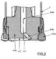
- the flushing air is in this case being led as an advantageous embodiment particularly with reference to the implementations shown in figure 3 from a main channel 6; 6a in the first frame part 4a by one or several distribution channels 6; 6b directed outward from center toward a counterpart surface X' existing in the first frame part.
- the method is exploited when operating with a drilling apparatus, in which the drilling head of the drilling device 1 is formed of a first frame part 4a and a second frame part 5a, the drilling surfaces P1, P2 of which being provided with drilling organs of the first and the second drilling means 4, 5, such as an integrated drilling parts, separate drilling pieces, bits or like, and whereby a reamer is being used as the second drilling means 5 that operates on eccentric principle, being non-cymmetrical and that opens radially outward for drilling.
- the flushing air is in this case being led from a main channel 6; 6a in the first frame part 4a by one or several distribution channels 6; 6b, being directed outward from center, toward a counterpart surface X' existing in the first 4a frame part.
- speed and/or direction of the flushing air flow HV is altered by a flow space X", being in connection with the counterpart surface X; X' and the cross-section of which being increased in respect to the same of the distribution channel 6; 6b and/or directed to a differing direction.
- the invention relates also to an apparatus for down-the-hole drilling as explained above, in which an end of the drilling unit 3 is provided with a counterpart surface arrangement X, which is meant particularly for decreasing kinetic energy of a flushing air flow HV to be brought into the drilling surface P1, P2 of the first and/or second drilling means, by changing its flow direction prior to drifting thereof into the ground.
- a drilling head of the drilling device 1 of the apparatus according to the invention is formed furthermore advantageously of a first frame part 4a and a second frame part 5a, the drilling surfaces P1, P2 of which being provided with drilling organs of the first and the second drilling means 4, 5, such as an integrated drilling part, separate drilling pieces, bits or like.
- the second drilling means 5 comprise a reamer that has an essentially continuing drilling surface radially when viewed in a cross-section perpendicular to a longitudinal direction s of the drilling unit 3.
- the flushing flow arrangement comprises a counterpart surface X; X' in the first frame part 4a.
- one or several distribution channels 6; 6b existing in the first frame part 4a and being directed outward from center, is/are led toward the above counterpart surface.
- a reamer is being used as the second drilling means 5 that operates on eccentric principle, being non-cymmetrical and that opens radially outward for drilling.
- the flushing flow arrangement comprises first of all a counterpart surface X; X' in the first frame part 4a.
- the counterpart surface arrangement comprises furthermore a flow space X", the cross-section of which is increased in respect to the distribution channel 6; 6b and/or being directed to a differing direction therefrom as shown in figure 3 particularly in order to alter speed and/or direction of the flushing air flow HV.
- the flow space X; X" is arranged by a recess in the first frame part 4a, at an end of the distribution channel 6; 6b on the drilling surface P1.
- the counterpart surface X; X' is arranged essentially perpendicularly to the flushing air flow HV.
- the casing shoe can be placed in an integrated manner at the end of the casing part etc. It is furthermore possible to complement the flushing flow arrangement e.g. by a flow pipe connected to the space between the casing part and the drilling unit e.g. in order to keep the space surrounding the drilling unit empty, and/or by a flushing assembly that greases the joint between the drilling means and the casing shoe etc.
Description
- The invention relates to a method and apparatus for down-the-hole drilling according to the preambles of the independent claims.
- For example in patent publication
FI 75650 - A way to carry out overburden drilling in a more developed manner compared to prior art, is formerly known e.g. from Finnish. Patent No.
95618 - Document
WO96/15351 - Furthermore document
FR 2889 556 - Particularly a so called pile drilling has rapidly become common in making of both so called micro piles and large-diameter foundation piles. An advantage of pile drilling is among other things the fact that drilled piles can be mounted quickly and accurately in a desired position, direction and depth. Straightness of the piles, verification of the bottom and accurate positioning are factors, thanks to which the pile drilling has often taken the place of pile driving particularly in demanding construction sites. A drilled pile displaces a corresponding amount of soil to its volume by bringing up the drilled soil entirely. This is why not any horizontal strains will be caused that might brake surrounding structures, which may take place when piles are rammed. Pile drilling is also relatively silent and quite shakeless (the operating frequency of the hammer is higher than the natural frequencies of soil and structures) when compared to piles being rammed. On the other hand the possibility offered by a drilled pile to get a casing pipe mounted reliably and without efforts even into a sloping rock surface, are superiority factors when comparing the method to piling by digging.
- Thus a significant number of superiority factors are related to pile drilling, which in practice very often make the same as the most recommendable alternative. Thanks to the pile drilling being the most efficient piling method also by its production capacity and due to the fact that it enables piling with relatively small, easily transportable, and space-saving machines that can be put quickly into working order, also foundation constructors almost without exception take up a positive attitude towards the same.
- Pile drilling uses pressurized air for operating the down-the-hole hammer and as the means for bringing up the loosened material. Careless use of air in flushing has brought about, however, some problems, solving of which is necessary for the standpoint of development regarding pile drilling.
- Problems caused by flushing air can be devided in two main categories:
- use of flushing air may overdrill an excessive amount of material on surface of the earth, in which case both the foundation to be built and surrounding structures are in danger. This is a typical situation particularly with frictional soil (sand, silt etc.),
- the second problem is due to "pushing" of air into the soil particularly in case of cohesive soil (such as clay), whereby air may get drifted around load supporting piles (e.g. rammed wood piles) existing in the neighbourhood, in which case weight carrying capacity of the pile (or piles) may decrease very quickly.
- Careless use of flushing air has already led to denial of pile drilling by a down-the-hole hammer among other things in some sites, which have been grounded on support of old wood piles driven in cohesive soil, in which case air that has been "escaped" into the soil has caused sudden sinkings and cracks in buildings. On the other hand in some sites, a significantly greater amount of soil has been over drilled by flushing air than the piles have actually replaced, due to which surrounding buildings have been caused to tilt.
- Because down-the-hole hammer drilling is, however, a very efficient way to operate, applicable for all soil circumstances and because the piles erected by the same are straight and reliable, the disadvantages related to its use need to be eliminated in order to enable down-the-hole hammer drilling also in the future.
- As stated above, the problems caused by the use of flushing air in down-the-hole hammer drilling are usually due to poor professional skill or carelessness of the operating personnel, but in practice also drill bit structures and drilling techniques may effect essentially to arising of the problems. In this context e.g. drill bits are originally designed usually for rock drilling, whereby the flushing air must first of all be directed as efficiently as possible to the drilled point for removing of the particles quickly in order to avoid multiple crushing, and on the other hand with such a volume (and speed), that the material gets brought up through the casing. This is why the flushing openings of the drill bits are thus aimed directly at the rock surface. During drilling the flushing air may not get back upwards in rock hole, but along a hole with unbroken walls. The situation is, however, different in overburden drilling, whereby the ground may penetrate air even very easily. In this case turning of the flushing air back to the casing pipe or in connection therewith is very problematic or even impossible, if carried out by traditional drill bits. On the other hand, a large amount of air is needed for lifting of the soil, which leads also to a high velocity inside the casing pipe and to very effective blowing of flushing air directly to the soil.
- A very controlled air circulation is thus required of bits operating under such circumstances or in other words when the flushing air is returned back to the casing pipe or in connection therewith though the soil was relatively easily air permeable. The drilling action must be performed on the other hand in a space protected as well as possible so that the pressure of the ground does not block input openings of the flushing air or in other words so that the pressure of the flushing air to be fed exceeds the pressure of the ground and on the other hand so that the easiest way for air from the drilled point takes place in a desired manner back to the casing part or in connection therewith.
- It is an aim of the method and apparatus according to the present invention to achieve a decisive improvement in the problems described above and thus to raise essentially the level of prior art. In order to carry out this aim, the method and apparatus according to the invention are mainly characterized by what has been presented in the characterizing parts of the independent claims related thereto.
- As the most important advantages of the method and apparatus according to the invention may be mentioned simplicity and efficiency of the constructions and operating principles enabled by the same first of all thanks to the fact that it is possible to exploit therewith drill bit constructions that have been found technically very well functionable. On the other hand the invention enables further use of pressurized air as flushing medium thanks to the drilling head of the drilling unit being provided with a counterpart surface arrangement according to the invention operating idealistically so that a direct flow of flushing air may not get directed to the soil, which is why among other things overdrilling and foundations of surrounding structures getting damaged can be avoided, which is nowadays being tried to prevent when drilling by present technique e.g. by protective pilings limiting the drilling site, which become naturally disproportionately expensive. With the method and apparatus according to the invention thanks to improvement of safety, it is thus possible to achieve also clear savings in performing of the drilling itself.
- Advantageous embodiments of the method and apparatus according to the invention have been presented in the dependent claims related thereto.
- In the following description the invention is depicted in detail with reference to the appended drawings, in which
- in
figure 1 is shown an example of the method and apparatus not forming part of the present invention when exploiting a so called symmetrical drilling unit, which is based on removal of drilling waste internally in the casing part, - in
figure 2 is shown an advantageous embodiment of the method and apparatus when exploiting a drilling unit operating on eccentric principle, in which drilling waste is removed internally in the casing part, - in
figure 3 is shown a partial cross-sectional view from an end of a symmetric drilling unit according to the invention, in which drilling waste is removed externally in respect of the casing part, and - in
figure 4 is shown a partial cross-sectional view from an implementation according to the invention in connection with a drilling unit based on eccentric principle, in which drilling waste goes away externally in respect of the casing part. - The invention relates to a method for down-the-hole drilling, the drilling being carried out by an apparatus, having a
drilling device 1 that comprises acasing part 2 and at least during a drilling situation an essentially inside thereof existingdrilling unit 3, at the drilling head of which there are at least first drilling means 4 for drilling a center hole, second drilling means 5 for reaming the center hole for thecasing part 2 and a pneumaticflushing flow arrangement 6 for leading of drilling waste by influence of pressurized air at least partly upward. The first drilling means 4 are coupled with the second drilling means 5 first of all power-transmittedly in order to carry out cooperation thereof at least during a drilling situation with the second drilling means 5 for a rotational motion w4, a feeding motion z4 and/or a hammering motion t4 produced by ahammer device 7 and on the other hand removably in order to enable removal thereof from the hole. Thecasing part 2 is furthermore arranged to be drawn into a hole to be drilled by thedrilling unit 3. Flushing air is led while being led onto the drilling surface P1, P2 of the first and/or second drilling means into a counterpart surface arrangement X existing essentially at an end of adrilling unit 3, particularly in order to decrease kinetic energy thereof by changing its flow direction prior to drifting thereof into the ground. - In the method it is being exploited when operating with a drilling apparatus, in which the drilling head of the
drilling device 1 is formed of afirst frame part 4a and asecond frame part 5a, the drilling surfaces P1, P2 of which being provided with drilling organs of the first and the second drilling means 4, 5, such as an integrated drilling part, separate drilling pieces, bits or like, and whereby a reamer is being used as the second drilling means 5 that has an essentially continuing drilling surface radially when viewed in a cross-section perpendicular to a longitudinal direction s of thedrilling unit 3. The flushing air is in this case being led as an advantageous embodiment particularly with reference to the implementations shown infigure 3 from amain channel 6; 6a in thefirst frame part 4a by one orseveral distribution channels 6; 6b directed outward from center toward a counterpart surface X' existing in the first frame part. - With reference to the embodiments shown in
figures 2 and4 , respectively, the method is exploited when operating with a drilling apparatus, in which the drilling head of thedrilling device 1 is formed of afirst frame part 4a and asecond frame part 5a, the drilling surfaces P1, P2 of which being provided with drilling organs of the first and the second drilling means 4, 5, such as an integrated drilling parts, separate drilling pieces, bits or like, and whereby a reamer is being used as the second drilling means 5 that operates on eccentric principle, being non-cymmetrical and that opens radially outward for drilling. The flushing air is in this case being led from amain channel 6; 6a in thefirst frame part 4a by one orseveral distribution channels 6; 6b, being directed outward from center, toward a counterpart surface X' existing in the first 4a frame part. - Furthermore with reference to the appended drawings, speed and/or direction of the flushing air flow HV is altered by a flow space X", being in connection with the counterpart surface X; X' and the cross-section of which being increased in respect to the same of the
distribution channel 6; 6b and/or directed to a differing direction. - The invention relates also to an apparatus for down-the-hole drilling as explained above, in which an end of the
drilling unit 3 is provided with a counterpart surface arrangement X, which is meant particularly for decreasing kinetic energy of a flushing air flow HV to be brought into the drilling surface P1, P2 of the first and/or second drilling means, by changing its flow direction prior to drifting thereof into the ground. - A drilling head of the
drilling device 1 of the apparatus according to the invention is formed furthermore advantageously of afirst frame part 4a and asecond frame part 5a, the drilling surfaces P1, P2 of which being provided with drilling organs of the first and the second drilling means 4, 5, such as an integrated drilling part, separate drilling pieces, bits or like. Particularly with reference to the embodiments shown infigures 1 and3 , the second drilling means 5 comprise a reamer that has an essentially continuing drilling surface radially when viewed in a cross-section perpendicular to a longitudinal direction s of thedrilling unit 3. In this case, the flushing flow arrangement comprises a counterpart surface X; X' in thefirst frame part 4a. Furthermore one orseveral distribution channels 6; 6b existing in thefirst frame part 4a and being directed outward from center, is/are led toward the above counterpart surface. - Furthermore as an embodiment of the apparatus according to the invention particularly with reference to the exemplary implementations shown in
figures 2 and4 , a reamer is being used as the second drilling means 5 that operates on eccentric principle, being non-cymmetrical and that opens radially outward for drilling. In this case the flushing flow arrangement comprises first of all a counterpart surface X; X' in thefirst frame part 4a. On the other hand one orseveral distribution channels 6; 6b existing in thefirst frame part 4a and being directed outward from the center, is/are led toward the above counterpart surface. - The counterpart surface arrangement comprises furthermore a flow space X", the cross-section of which is increased in respect to the
distribution channel 6; 6b and/or being directed to a differing direction therefrom as shown infigure 3 particularly in order to alter speed and/or direction of the flushing air flow HV. In the embodiments shown infigures 1 ,2 and4 , the flow space X; X" is arranged by a recess in thefirst frame part 4a, at an end of thedistribution channel 6; 6b on the drilling surface P1. Correspondingly with respect tofigure 3 , in the exemplary implementation presented therein, the counterpart surface X; X' is arranged essentially perpendicularly to the flushing air flow HV. - It is clear that the invention is not limited to the embodiments presented or described above, but instead it can be modified within the basic idea of the invention according to the needs at any given time. It is thus clear that the constructions of the drilling heads being illustrated in the appended drawings may vary in practice very much merely when being carried out with differing diameters. Instead of the type of embodiments shown in
figures 2 or4 , it is naturally possible to use as the drilling device also other drilling devices that are applicable for the same purpose, in which a casing part is being exploited in connection with the drilling so that is most advantageously not rotated when being drawn into the ground. It is not that significant for the method and the apparatus according to the invention, either, how the first and second drilling means are coupled to work, so that most heterogeneous solutions can be exploited as the power transmission assemblies between the same starting from a screw joint locking. Also the casing shoe can be placed in an integrated manner at the end of the casing part etc. It is furthermore possible to complement the flushing flow arrangement e.g. by a flow pipe connected to the space between the casing part and the drilling unit e.g. in order to keep the space surrounding the drilling unit empty, and/or by a flushing assembly that greases the joint between the drilling means and the casing shoe etc.
Claims (6)
- Method for down-the-hole drilling, the drilling being carried out by an apparatus, having a drilling device (1) that comprises a casing part (2) and at least during a drilling situation an essentially inside thereof existing drilling unit (3), at the drilling head of which there are at least first drilling means (4) for drilling a center hole, second drilling means (5) for reaming the center hole for the casing part (2) and a flushing flow arrangement (6) for leading of a pressurized flushing air for drilling through a centric main channel (6a1) in order to direct the flushing air by means of one or more distribution channels (6b) from the centric main channel through a drilling surface (P1) of the first drilling means (4) and for leading of drilling waste at least partly upward, whereby the first drilling means (4) are coupled with the second drilling means (5) power-transmittedly in order to carry out cooperation thereof at least during a drilling situation with the second drilling means (5) for a rotational motion (w4), a feeding motion (z4) and/or a hammering motion (t4), wherein direct aiming of a flushing air flow (HV) at the soil is being prevented by means of a counterpart surface arrangement in order to decrease kinetic energy of the flushing air flow prior to drifting thereof into the ground by directing the flushing air at an end of the drilling unit (3) into a counterpart surface (X') and a flow space (X"), by means of which direction and speed of the flushing air flow (HV) is being altered, wherein a cross-section of the flow space is increased in respect with a cross-section of the distribution channel (6b) and the flow space is directed to a different direction than the distribution channel, and wherein the drilling head of the drilling device (1) is formed of a first frame part (4a) and a second frame part (5a), comprising respectively the drilling surface (P1) of the first drilling means (4) and a drilling surface (P2) of the second drilling means (5) being respectively provided with drilling organs of the first and the second drilling means (4, 5), such as an integrated drilling part, separate drilling pieces, bits or like, characterized in that the flushing air is being led through the distribution channel (6b) to the flow space (X;X") that is arranged by a recess with the counterpart surface (X;X') in the first frame part (4a) at the end of the distribution channel on the drilling surface (P1) of the first drilling means (4).
- Method according to claim 1, characterized in that in the method a reamer is being used in the drilling apparatus as the second drilling means (5) that has an essentially continuing drilling surface radially, when viewed in a cross-section perpendicular to a longitudinal direction (s) of the drilling unit (3), and wherein the first drilling means (4) are coupled with the second drilling means (5) removably in order to enable removal thereof from the drilled hole.
- Method according to claim 1, characterized in that in the method a reamer is being used in the drilling apparatus as the second drilling means (5) that operates on eccentric principle, being non-symmetrical and that opens radially outward for drilling.
- Apparatus for down-the-hole drilling, having a drilling device (1) that comprises a casing part (2) and at least during a drilling situation an essentially inside thereof existing drilling unit (3), at the drilling head of which there are at least first drilling means (4) for drilling a center hole, second drilling means (5) for reaming the center hole for the casing part (2) and a flushing flow arrangement (6) for leading of a pressurized flushing air for drilling through a centric main channel (6a1) in order to direct the flushing air by means of one or more distribution channels (6b) from the centric main channel through a drilling surface (P1) of the first drilling means (4) and for leading of drilling waste by influence of the pressurized flushing air at least partly upward, whereby the first drilling means (4) are coupled with the second drilling means (5) power-transmittedly in order to carry out cooperation thereof at least during a drilling situation with the second drilling means (5) for a rotational motion (w4), a feeding motion (z4) and/or a hammering motion (t4), wherein, in order to prevent direct aiming of a flushing air flow (HV) at the soil, the drilling unit (3) comprises a counterpart surface arrangement in order to decrease kinetic energy of the flushing air flow prior to drifting thereof into the ground by means of a counterpart surface (X') and a flow space (X") that alter direction and speed of the flushing air flow (HV), wherein a cross-section of the flow space is increased in respect with a cross-section of the distribution channel (6b) and the flow space is directed to a different direction than the distribution channel, and wherein the drilling head of the drilling device (1) is formed of a first frame part (4a) and a second frame part (5a), comprising respectively the drilling surface (P1) of the first drilling means (4) and a drilling surface (P2) of the second drilling means (5) being respectively provided with drilling organs of the first and the second drilling means (4, 5), such as an integrated drilling parts, separate drilling pieces, bits or like, characterized in that the flow space (X") is arranged by a recess with the counterpart surface (X;X') in the first frame part (4a) at the end of the distribution channel on the drilling surface (P1) of the first drilling means (4).
- Apparatus according to claim 4, characterized in that the second drilling means (5) comprise a reamer that has an essentially continuing drilling surface radially, when viewed in a cross-section perpendicular to a longitudinal direction (s) of the drilling unit (3), and wherein the first drilling means (4) are coupled with the second drilling means (5) removably in order to enable removal thereof from the drilled hole.
- Apparatus according to claim 4, characterized in that the second drilling means (5) comprise a reamer that operates on eccentric principle being non-symmetrical and that opens radially outward for drilling.
Applications Claiming Priority (2)
| Application Number | Priority Date | Filing Date | Title |
|---|---|---|---|
| FI20086206A FI20086206A0 (en) | 2008-12-17 | 2008-12-17 | Method and equipment for submersible drilling |
| PCT/FI2009/050820 WO2010070190A1 (en) | 2008-12-17 | 2009-10-13 | Method and apparatus for down-the-hole drilling |
Publications (3)
| Publication Number | Publication Date |
|---|---|
| EP2370660A1 EP2370660A1 (en) | 2011-10-05 |
| EP2370660A4 EP2370660A4 (en) | 2018-02-21 |
| EP2370660B1 true EP2370660B1 (en) | 2020-07-15 |
Family
ID=40240604
Family Applications (1)
| Application Number | Title | Priority Date | Filing Date |
|---|---|---|---|
| EP09832986.5A Active EP2370660B1 (en) | 2008-12-17 | 2009-10-13 | Method and apparatus for down-the-hole drilling |
Country Status (3)
| Country | Link |
|---|---|
| EP (1) | EP2370660B1 (en) |
| FI (1) | FI20086206A0 (en) |
| WO (1) | WO2010070190A1 (en) |
Families Citing this family (5)
| Publication number | Priority date | Publication date | Assignee | Title |
|---|---|---|---|---|
| FI20106154A0 (en) * | 2010-11-03 | 2010-11-03 | Atlas Copco Rotex Ab Oy | Method and apparatus for connecting a ground pipe to the ground |
| CN102477846B (en) * | 2010-11-27 | 2014-04-30 | 中铁西北科学研究院有限公司 | Soil-layer broaching bit |
| WO2017089647A1 (en) * | 2015-11-26 | 2017-06-01 | Oy Atlas Copco Rotex Ab | Method in down-the-hole drilling and a down-the-hole drilling device |
| FI128986B (en) * | 2017-03-01 | 2021-04-30 | Robit Oyj | A drill bit for percussive drilling, a drill bit assembly, and a method for manufacturing such a drill bit |
| CN110263497B (en) * | 2019-07-19 | 2021-12-07 | 南京航空航天大学 | Pneumatic coupling influence analysis method based on relative gain |
Family Cites Families (9)
| Publication number | Priority date | Publication date | Assignee | Title |
|---|---|---|---|---|
| SE421551B (en) | 1980-03-26 | 1982-01-04 | Sandvik Ab | DRILLING TOOL FOR ROTATION AND / OR DRILLING |
| DE3039633C2 (en) * | 1980-10-21 | 1983-08-18 | Christensen, Inc., 84115 Salt Lake City, Utah | Rotary drill bits, in particular for deep drilling |
| FR2566832B1 (en) * | 1984-06-27 | 1986-11-14 | Inst Francais Du Petrole | METHOD AND IMPROVEMENT IN DRILLING TOOLS PROVIDING HIGH EFFICIENCY IN CLEANING THE PRUNING FRONT |
| FI95618C (en) | 1992-12-03 | 1998-09-03 | Jorma Jaervelae | Downhole |
| FI945367A (en) | 1994-11-14 | 1996-05-15 | Valto Ilomaeki | Cutting arrangement for drilling device and method for removing drilling waste |
| FI98650C (en) * | 1995-11-06 | 1997-07-25 | Valto Ilomaeki | Impactor drilling unit |
| US6971458B2 (en) * | 2000-11-27 | 2005-12-06 | Shell Oil Company | Drill bit |
| EP1731708B1 (en) * | 2005-06-10 | 2007-08-08 | Geomechanik Wasser- und Umwelttechnik GmbH | Sledgehammer drilling apparatus and method |
| FR2889556B1 (en) | 2005-08-04 | 2007-09-21 | Gerard Arsonnet | DEVICE FOR DRILLING A WELL FOLLOWING A DRILLING AXIS FOR MEASURING A PARAMETER OF A PART OF A GROUND |
-
2008
- 2008-12-17 FI FI20086206A patent/FI20086206A0/en not_active Application Discontinuation
-
2009
- 2009-10-13 EP EP09832986.5A patent/EP2370660B1/en active Active
- 2009-10-13 WO PCT/FI2009/050820 patent/WO2010070190A1/en active Application Filing
Non-Patent Citations (1)
| Title |
|---|
| None * |
Also Published As
| Publication number | Publication date |
|---|---|
| WO2010070190A1 (en) | 2010-06-24 |
| EP2370660A4 (en) | 2018-02-21 |
| EP2370660A1 (en) | 2011-10-05 |
| FI20086206A0 (en) | 2008-12-17 |
Similar Documents
| Publication | Publication Date | Title |
|---|---|---|
| EP2382368B1 (en) | Method and apparatus for down-the-hole drilling | |
| US4671367A (en) | Pole hole digger with percussive core drilling | |
| EP2370660B1 (en) | Method and apparatus for down-the-hole drilling | |
| KR101406159B1 (en) | Pile hole drilling apparatus | |
| US6409432B1 (en) | Downhole hammer-type core barrel and method of using same | |
| KR101302554B1 (en) | Bit of hammer for drilling the ground | |
| US20110198129A1 (en) | Method and drilling apparatus for down-the-hole drilling | |
| KR100683021B1 (en) | Large-caliber excavator for excavating ground and method thereof | |
| US6892834B1 (en) | Piloted drill barrel and method of using same | |
| CN112982400A (en) | Pile casing follow-up type drilling bored concrete pile drilling tool | |
| EP2675982B1 (en) | Method and apparatus for down-the-hole drilling | |
| KR102505718B1 (en) | Bit for drilling the weak ground | |
| EP0990765B1 (en) | Percussive core barrel | |
| KR20130027763A (en) | Hammer bit structure for air circulation | |
| JPH11256970A (en) | Excavating method for hard rock bed and its device | |
| KR100858865B1 (en) | Down hole bit | |
| JP4781195B2 (en) | Driving method for driving material and driving material for preceding excavation | |
| US20240093555A1 (en) | Excavation boring and shoring method and equipment | |
| CN214886838U (en) | Drill rod guiding device for assisting impact rotary rock drill to complete grooving operation | |
| KR100328367B1 (en) | An excavator head for construction work | |
| CN205063813U (en) | Hammer tied in a bundle | |
| EP3433463B1 (en) | Down-the-hole drilling device | |
| KR101396911B1 (en) | Drill bit assembly with a detachable air chamber and the reverse circulation drilling rig having it | |
| RU23905U1 (en) | SHOCK DRILL | |
| KR100323302B1 (en) | Hilling device for a perforator by using a crane |
Legal Events
| Date | Code | Title | Description |
|---|---|---|---|
| PUAI | Public reference made under article 153(3) epc to a published international application that has entered the european phase |
Free format text: ORIGINAL CODE: 0009012 |
|
| 17P | Request for examination filed |
Effective date: 20110628 |
|
| AK | Designated contracting states |
Kind code of ref document: A1 Designated state(s): AT BE BG CH CY CZ DE DK EE ES FI FR GB GR HR HU IE IS IT LI LT LU LV MC MK MT NL NO PL PT RO SE SI SK SM TR |
|
| DAX | Request for extension of the european patent (deleted) | ||
| RAP1 | Party data changed (applicant data changed or rights of an application transferred) |
Owner name: OY EPIROC DRILLING TOOLS AB |
|
| RA4 | Supplementary search report drawn up and despatched (corrected) |
Effective date: 20180123 |
|
| RIC1 | Information provided on ipc code assigned before grant |
Ipc: E21B 10/60 20060101ALI20180117BHEP Ipc: E21B 10/38 20060101AFI20180117BHEP Ipc: E21B 10/26 20060101ALI20180117BHEP Ipc: E21B 21/16 20060101ALI20180117BHEP Ipc: E21B 7/20 20060101ALI20180117BHEP |
|
| STAA | Information on the status of an ep patent application or granted ep patent |
Free format text: STATUS: EXAMINATION IS IN PROGRESS |
|
| 17Q | First examination report despatched |
Effective date: 20181019 |
|
| RAP1 | Party data changed (applicant data changed or rights of an application transferred) |
Owner name: TERRAROC FINLAND OY |
|
| GRAP | Despatch of communication of intention to grant a patent |
Free format text: ORIGINAL CODE: EPIDOSNIGR1 |
|
| STAA | Information on the status of an ep patent application or granted ep patent |
Free format text: STATUS: GRANT OF PATENT IS INTENDED |
|
| INTG | Intention to grant announced |
Effective date: 20200224 |
|
| GRAS | Grant fee paid |
Free format text: ORIGINAL CODE: EPIDOSNIGR3 |
|
| GRAA | (expected) grant |
Free format text: ORIGINAL CODE: 0009210 |
|
| STAA | Information on the status of an ep patent application or granted ep patent |
Free format text: STATUS: THE PATENT HAS BEEN GRANTED |
|
| AK | Designated contracting states |
Kind code of ref document: B1 Designated state(s): AT BE BG CH CY CZ DE DK EE ES FI FR GB GR HR HU IE IS IT LI LT LU LV MC MK MT NL NO PL PT RO SE SI SK SM TR |
|
| REG | Reference to a national code |
Ref country code: CH Ref legal event code: EP Ref country code: GB Ref legal event code: FG4D |
|
| REG | Reference to a national code |
Ref country code: IE Ref legal event code: FG4D |
|
| REG | Reference to a national code |
Ref country code: DE Ref legal event code: R096 Ref document number: 602009062437 Country of ref document: DE |
|
| REG | Reference to a national code |
Ref country code: AT Ref legal event code: REF Ref document number: 1291236 Country of ref document: AT Kind code of ref document: T Effective date: 20200815 |
|
| REG | Reference to a national code |
Ref country code: FI Ref legal event code: FGE |
|
| REG | Reference to a national code |
Ref country code: SE Ref legal event code: TRGR |
|
| REG | Reference to a national code |
Ref country code: LT Ref legal event code: MG4D |
|
| REG | Reference to a national code |
Ref country code: AT Ref legal event code: MK05 Ref document number: 1291236 Country of ref document: AT Kind code of ref document: T Effective date: 20200715 |
|
| REG | Reference to a national code |
Ref country code: NL Ref legal event code: MP Effective date: 20200715 |
|
| PG25 | Lapsed in a contracting state [announced via postgrant information from national office to epo] |
Ref country code: HR Free format text: LAPSE BECAUSE OF FAILURE TO SUBMIT A TRANSLATION OF THE DESCRIPTION OR TO PAY THE FEE WITHIN THE PRESCRIBED TIME-LIMIT Effective date: 20200715 Ref country code: ES Free format text: LAPSE BECAUSE OF FAILURE TO SUBMIT A TRANSLATION OF THE DESCRIPTION OR TO PAY THE FEE WITHIN THE PRESCRIBED TIME-LIMIT Effective date: 20200715 Ref country code: NO Free format text: LAPSE BECAUSE OF FAILURE TO SUBMIT A TRANSLATION OF THE DESCRIPTION OR TO PAY THE FEE WITHIN THE PRESCRIBED TIME-LIMIT Effective date: 20201015 Ref country code: GR Free format text: LAPSE BECAUSE OF FAILURE TO SUBMIT A TRANSLATION OF THE DESCRIPTION OR TO PAY THE FEE WITHIN THE PRESCRIBED TIME-LIMIT Effective date: 20201016 Ref country code: AT Free format text: LAPSE BECAUSE OF FAILURE TO SUBMIT A TRANSLATION OF THE DESCRIPTION OR TO PAY THE FEE WITHIN THE PRESCRIBED TIME-LIMIT Effective date: 20200715 Ref country code: LT Free format text: LAPSE BECAUSE OF FAILURE TO SUBMIT A TRANSLATION OF THE DESCRIPTION OR TO PAY THE FEE WITHIN THE PRESCRIBED TIME-LIMIT Effective date: 20200715 Ref country code: PT Free format text: LAPSE BECAUSE OF FAILURE TO SUBMIT A TRANSLATION OF THE DESCRIPTION OR TO PAY THE FEE WITHIN THE PRESCRIBED TIME-LIMIT Effective date: 20201116 Ref country code: BG Free format text: LAPSE BECAUSE OF FAILURE TO SUBMIT A TRANSLATION OF THE DESCRIPTION OR TO PAY THE FEE WITHIN THE PRESCRIBED TIME-LIMIT Effective date: 20201015 |
|
| PG25 | Lapsed in a contracting state [announced via postgrant information from national office to epo] |
Ref country code: PL Free format text: LAPSE BECAUSE OF FAILURE TO SUBMIT A TRANSLATION OF THE DESCRIPTION OR TO PAY THE FEE WITHIN THE PRESCRIBED TIME-LIMIT Effective date: 20200715 Ref country code: LV Free format text: LAPSE BECAUSE OF FAILURE TO SUBMIT A TRANSLATION OF THE DESCRIPTION OR TO PAY THE FEE WITHIN THE PRESCRIBED TIME-LIMIT Effective date: 20200715 Ref country code: IS Free format text: LAPSE BECAUSE OF FAILURE TO SUBMIT A TRANSLATION OF THE DESCRIPTION OR TO PAY THE FEE WITHIN THE PRESCRIBED TIME-LIMIT Effective date: 20201115 |
|
| PG25 | Lapsed in a contracting state [announced via postgrant information from national office to epo] |
Ref country code: NL Free format text: LAPSE BECAUSE OF FAILURE TO SUBMIT A TRANSLATION OF THE DESCRIPTION OR TO PAY THE FEE WITHIN THE PRESCRIBED TIME-LIMIT Effective date: 20200715 |
|
| REG | Reference to a national code |
Ref country code: DE Ref legal event code: R097 Ref document number: 602009062437 Country of ref document: DE |
|
| PG25 | Lapsed in a contracting state [announced via postgrant information from national office to epo] |
Ref country code: RO Free format text: LAPSE BECAUSE OF FAILURE TO SUBMIT A TRANSLATION OF THE DESCRIPTION OR TO PAY THE FEE WITHIN THE PRESCRIBED TIME-LIMIT Effective date: 20200715 Ref country code: SM Free format text: LAPSE BECAUSE OF FAILURE TO SUBMIT A TRANSLATION OF THE DESCRIPTION OR TO PAY THE FEE WITHIN THE PRESCRIBED TIME-LIMIT Effective date: 20200715 Ref country code: IT Free format text: LAPSE BECAUSE OF FAILURE TO SUBMIT A TRANSLATION OF THE DESCRIPTION OR TO PAY THE FEE WITHIN THE PRESCRIBED TIME-LIMIT Effective date: 20200715 Ref country code: DK Free format text: LAPSE BECAUSE OF FAILURE TO SUBMIT A TRANSLATION OF THE DESCRIPTION OR TO PAY THE FEE WITHIN THE PRESCRIBED TIME-LIMIT Effective date: 20200715 Ref country code: EE Free format text: LAPSE BECAUSE OF FAILURE TO SUBMIT A TRANSLATION OF THE DESCRIPTION OR TO PAY THE FEE WITHIN THE PRESCRIBED TIME-LIMIT Effective date: 20200715 Ref country code: CZ Free format text: LAPSE BECAUSE OF FAILURE TO SUBMIT A TRANSLATION OF THE DESCRIPTION OR TO PAY THE FEE WITHIN THE PRESCRIBED TIME-LIMIT Effective date: 20200715 |
|
| REG | Reference to a national code |
Ref country code: DE Ref legal event code: R119 Ref document number: 602009062437 Country of ref document: DE |
|
| PLBE | No opposition filed within time limit |
Free format text: ORIGINAL CODE: 0009261 |
|
| STAA | Information on the status of an ep patent application or granted ep patent |
Free format text: STATUS: NO OPPOSITION FILED WITHIN TIME LIMIT |
|
| REG | Reference to a national code |
Ref country code: CH Ref legal event code: PL |
|
| 26N | No opposition filed |
Effective date: 20210416 |
|
| GBPC | Gb: european patent ceased through non-payment of renewal fee |
Effective date: 20201015 |
|
| PG25 | Lapsed in a contracting state [announced via postgrant information from national office to epo] |
Ref country code: LU Free format text: LAPSE BECAUSE OF NON-PAYMENT OF DUE FEES Effective date: 20201013 Ref country code: SK Free format text: LAPSE BECAUSE OF FAILURE TO SUBMIT A TRANSLATION OF THE DESCRIPTION OR TO PAY THE FEE WITHIN THE PRESCRIBED TIME-LIMIT Effective date: 20200715 Ref country code: MC Free format text: LAPSE BECAUSE OF FAILURE TO SUBMIT A TRANSLATION OF THE DESCRIPTION OR TO PAY THE FEE WITHIN THE PRESCRIBED TIME-LIMIT Effective date: 20200715 |
|
| REG | Reference to a national code |
Ref country code: BE Ref legal event code: MM Effective date: 20201031 |
|
| PG25 | Lapsed in a contracting state [announced via postgrant information from national office to epo] |
Ref country code: DE Free format text: LAPSE BECAUSE OF NON-PAYMENT OF DUE FEES Effective date: 20210501 Ref country code: FR Free format text: LAPSE BECAUSE OF NON-PAYMENT OF DUE FEES Effective date: 20201031 |
|
| PG25 | Lapsed in a contracting state [announced via postgrant information from national office to epo] |
Ref country code: SI Free format text: LAPSE BECAUSE OF FAILURE TO SUBMIT A TRANSLATION OF THE DESCRIPTION OR TO PAY THE FEE WITHIN THE PRESCRIBED TIME-LIMIT Effective date: 20200715 Ref country code: LI Free format text: LAPSE BECAUSE OF NON-PAYMENT OF DUE FEES Effective date: 20201031 Ref country code: GB Free format text: LAPSE BECAUSE OF NON-PAYMENT OF DUE FEES Effective date: 20201015 Ref country code: BE Free format text: LAPSE BECAUSE OF NON-PAYMENT OF DUE FEES Effective date: 20201031 Ref country code: CH Free format text: LAPSE BECAUSE OF NON-PAYMENT OF DUE FEES Effective date: 20201031 |
|
| PG25 | Lapsed in a contracting state [announced via postgrant information from national office to epo] |
Ref country code: TR Free format text: LAPSE BECAUSE OF FAILURE TO SUBMIT A TRANSLATION OF THE DESCRIPTION OR TO PAY THE FEE WITHIN THE PRESCRIBED TIME-LIMIT Effective date: 20200715 Ref country code: MT Free format text: LAPSE BECAUSE OF FAILURE TO SUBMIT A TRANSLATION OF THE DESCRIPTION OR TO PAY THE FEE WITHIN THE PRESCRIBED TIME-LIMIT Effective date: 20200715 Ref country code: CY Free format text: LAPSE BECAUSE OF FAILURE TO SUBMIT A TRANSLATION OF THE DESCRIPTION OR TO PAY THE FEE WITHIN THE PRESCRIBED TIME-LIMIT Effective date: 20200715 |
|
| PG25 | Lapsed in a contracting state [announced via postgrant information from national office to epo] |
Ref country code: MK Free format text: LAPSE BECAUSE OF FAILURE TO SUBMIT A TRANSLATION OF THE DESCRIPTION OR TO PAY THE FEE WITHIN THE PRESCRIBED TIME-LIMIT Effective date: 20200715 |
|
| P01 | Opt-out of the competence of the unified patent court (upc) registered |
Effective date: 20230528 |
|
| PGFP | Annual fee paid to national office [announced via postgrant information from national office to epo] |
Ref country code: SE Payment date: 20231031 Year of fee payment: 15 Ref country code: IE Payment date: 20231031 Year of fee payment: 15 Ref country code: FI Payment date: 20231031 Year of fee payment: 15 |