EP2369880A1 - Method and device for synchronizing nodes of a mesh wireless network - Google Patents
Method and device for synchronizing nodes of a mesh wireless network Download PDFInfo
- Publication number
- EP2369880A1 EP2369880A1 EP10305282A EP10305282A EP2369880A1 EP 2369880 A1 EP2369880 A1 EP 2369880A1 EP 10305282 A EP10305282 A EP 10305282A EP 10305282 A EP10305282 A EP 10305282A EP 2369880 A1 EP2369880 A1 EP 2369880A1
- Authority
- EP
- European Patent Office
- Prior art keywords
- node
- nodes
- synchronization
- state
- neighboring nodes
- Prior art date
- Legal status (The legal status is an assumption and is not a legal conclusion. Google has not performed a legal analysis and makes no representation as to the accuracy of the status listed.)
- Granted
Links
Images


Classifications
-
- H—ELECTRICITY
- H04—ELECTRIC COMMUNICATION TECHNIQUE
- H04W—WIRELESS COMMUNICATION NETWORKS
- H04W56/00—Synchronisation arrangements
- H04W56/001—Synchronization between nodes
- H04W56/002—Mutual synchronization
-
- H—ELECTRICITY
- H04—ELECTRIC COMMUNICATION TECHNIQUE
- H04J—MULTIPLEX COMMUNICATION
- H04J3/00—Time-division multiplex systems
- H04J3/02—Details
- H04J3/06—Synchronising arrangements
- H04J3/0635—Clock or time synchronisation in a network
- H04J3/0676—Mutual
Definitions
- the present invention relates to a method for synchronizing nodes of a mesh wireless network and to a device for implementing such a method.
- the invention relates more particularly to the synchronization of home base stations (HeNBs).
- HeNBs home base stations
- Such home base stations are deployed, for example, for providing a seamless wireless network inside houses or in a building of a company, a mall, a station or more generally any large building.
- the number of HeNBs is large.
- each node can listen to the closest neighbor signal and align its synchronization to the received signal.
- the wireless network is dense, i.e., when each node is surrounded by several nodes, it is better to make a trade-off between all the neighboring nodes synchronization time.
- each node transmits to its neighboring nodes a synchronization signal aligned to a synchronization time dedicated to said node and each node determines its synchronization time based on the synchronization signal.
- the invention accordingly gives a solution to the above problem by proposing a synchronization method for a mesh wireless network which is fully distributed among the nodes to be synchronized.
- the method relates to a method for synchronizing nodes of a mesh wireless network, each node transmitting to its neighboring nodes a synchronization signal aligned to a synchronization time dedicated to said node and each node determining its synchronization time based on the synchronization signal, characterized in that it comprises the steps, carried for each node, of:
- the method for synchronizing nodes comprises one or more of the following characteristics:
- the invention also relates to a device for synchronizing nodes of a mesh wireless network, each node transmitting to its neighboring nodes a synchronization signal aligned to a synchronization time dedicated to said node and each node determining its synchronization time based on the synchronization signal, characterized in that it comprises means, provided at each node, for:
- Figure 1 illustrates a plurality of nodes 1, 2, 3, 4, 5, 6, 7, 8, 9, 10, 11, 12, 13 of a mesh wireless network 20.
- the nodes 1 to 13 are communicating devices consisting for example in home base stations (HeNBs).
- HeNBs home base stations
- the network 20 also comprises base stations BS1 22 and BS2 24.
- each node can listen to the signals transmitted by other nodes or base stations of the network.
- a node when a node is in a reception state, it receives the signal of a neighboring node only if the link quality between the node and such neighboring node is sufficient.
- a line is drawn such as for example between the nodes 1 and 2 or between the node 1 and the base station BS1 22.
- each node 1 to 13 transmits to its neighboring nodes a synchronization signal during synchronization sub-frames in order to allow for its neighboring nodes to determine its synchronization time.
- Each node knows when synchronization sub-frames occur, for example by a coarse synchronization time estimation.
- node 8 transmits to its neighboring nodes, i.e. nodes 3, 4, 12, 11 and 9 a synchronization signal aligned to a synchronization time dedicated to said node 8 in order to allow these nodes to determine its synchronization time.
- the estimation of the synchronization time of a node by its neighboring nodes is not precise as the received signals at the neighboring nodes are impacted by an additive noise and delayed by the propagation delays which are unknown.
- the synchronization signal transmitted to neighboring nodes 3, 4, 12, 11 and 9 is delayed by propagation delays ⁇ 38, ⁇ 48, ⁇ 812, ⁇ 811 and ⁇ 89 respectively.
- the flow chart of Figure 2 illustrates the steps of the method for synchronizing the nodes of the mesh network 20 according to the invention.
- the node k detects a synchronization sub-frame.
- Step 34 indicates the test whether the node k is in a transmission state.
- the node k transmits in 38 its synchronization signal to the neighboring nodes and returns to step 30 of detection of a synchronization sub-frame.
- the node k receives in 42 the synchronization signals transmitted from the neighboring nodes in a transmission state and it extracts the relative synchronization times with respect to its own synchronization time of these transmitting neighboring nodes from the received synchronization signals.
- the node k combines its own synchronization time with the extracted synchronization times of the neighboring nodes.
- the node 4 corrects the combining result in order to reduce a synchronization time drift due to propagation delays between the nodes. This correction in step 46 will be detailed later in the description.
- the node k updates its synchronization time to be equal to the combining result.
- the node k returns to step 30 of detection of a synchronization sub-frame.
- the node k has N k neighboring nodes.
- each node chooses randomly, for example with equal probability, its state "transmission” or “reception” at each new iteration of the method, and in that the choice of the coefficient A j take into account this random behavior of the network for ensuring convergence to a situation where all nodes are synchronized altogether.
- the choice of the coefficients will be discussed in the following description.
- ⁇ ( ⁇ n,k ) is the weight coefficient associated to the actual synchronization time of the considered node k
- ⁇ j ( ⁇ n,k ) is a weight coefficient associated to the synchronization time of the node j received by the node k.
- the weights are chosen in order to guarantee a convergence of the system.
- ⁇ j ⁇ n , k ⁇ ⁇ n , k - 1 ⁇ n , k and ⁇ ⁇ n , k ⁇ 1.
- the system converges to a mean value plus a mismatch which is different for each node, and mainly depends on the propagation delays of the wireless links arriving at the node k.
- the ponderation value is a function of the number of nodes in a transmission state at the n-th iteration, and received by the considered node.
- the mismatch is a function of the average of the propagation delays on the communication links between the considered node k and the neighboring nodes.
- the mismatch decreases as the number of neighbours increases, or as the distribution of propagation delays is more equal for all nodes.
- two neighboring nodes have a similar radio environment, they will tend to the same synchronization time with a good probability.
- the nodes appear to be synchronized in a given neighborhood.
- the coefficient ⁇ ( ⁇ n,k ) can be chosen independently from the propagation delays, and lower than 1.
- the choice of ⁇ ( ⁇ n,k ) impacts the convergence speed of the algorithm.
- ⁇ j ( ⁇ n,k ) is a function of the path gain between nodes j and k.
- the method comprises a step of storing the synchronization times of all nodes in a table, the combining step 44 using the last stored synchronization time of all the neigboring nodes.
- the table of synchronization times of neighbors contains new and old values V j for each neighbor.
- the table also includes the synchronization time V k of the node itself.
- the weights in the linear combination are chosen to ensure the system convergence as a function of the number of neighboring nodes or as a function of the number of transmitting nodes at a given time.
- a delay spread is observed for the propagation of signals between two nodes.
- the considered node k learns the slope of the linear drift and corrects its estimated synchronization time by a value M k n .
- the M k n coefficient is adapted and classically computed, using for example, a classical Least Mean Squares adaptive algorithm, in order to minimize ⁇ ⁇ j A j ⁇ ⁇ kj ⁇ M k n ⁇ or with a statistical approach E ⁇ ⁇ ⁇ j A j ⁇ ⁇ kj - M k n ⁇ .
- this tracking also has the advantage of tracking the clock drift due to cheap hardware impairments, in a collaborative fashion, which is particularly useful when nodes are home base stations.
- a fourth embodiment particularly suitable if some nodes have other means of synchronization as optical fiber networks for example, aims at propagating these reference synchronization information to the other nodes.
- the method comprises defining different classes of nodes depending on their type of external synchronization means: none, optical, GPS... and broadcasting these classes along with the synchronization signals dedicated to the nodes.
- a node might change its probability of transmission or reception state. For example, for a node being synchronized to a very accurate clock (e.g. GPS), it should not switch into reception mode, and only inject the clock into the mesh wireless network.
- a very accurate clock e.g. GPS
- Each node detects if the received synchronization time belongs to one class of nodes and it weights the estimated synchronization time of said neighboring node accordingly. For example, by considering the example of Figure 1 , where base stations BS1 22 and BS2 24 are synchronized by a GPS, a node will consider large weights coefficients if the path gain of the base station to node transmission is large and low weights coefficients if the path gain of the base station to node transmission is low. Thus, nodes that are close to a base station (nodes 1 and 2 in Figure 1 for example) will be synchronized to the base station, and influence the whole nodes network as an anchor for the synchronization time. At the end, the whole network will be synchronized to the macro network, even nodes out of the coverage of macro cells.
- the method of the present invention is implemented in a device for synchronizing nodes comprising means allowing the implementation of the method described above.
- the method and device according to the invention are particularly useful when a propagation delay is observed between the nodes and it is more particularly well suited for applications of home base stations.
Landscapes
- Engineering & Computer Science (AREA)
- Computer Networks & Wireless Communication (AREA)
- Signal Processing (AREA)
- Mobile Radio Communication Systems (AREA)
- Synchronisation In Digital Transmission Systems (AREA)
Abstract
- randomly choosing (32) the state of said node between a transmission and a reception state;
- if the chosen state for said node is a transmission state (36), transmitting (38) the synchronization signal to the neighboring nodes;
- if the chosen state for said node is a reception state (40) :
- receiving (42) the synchronization signals transmitted from the neighboring nodes in a transmission state;
- extracting (42) the synchronization times of the neighboring nodes from the received synchronization signals;
- combining (44) the synchronization time of said node with the extracted synchronization times of the neighboring nodes; and
- updating (48) the synchronization time of said node to be equal to the combining result.
Description
- The present invention relates to a method for synchronizing nodes of a mesh wireless network and to a device for implementing such a method.
- The invention relates more particularly to the synchronization of home base stations (HeNBs). Such home base stations are deployed, for example, for providing a seamless wireless network inside houses or in a building of a company, a mall, a station or more generally any large building. Thus, in such a network, the number of HeNBs is large.
- There exist several methods for synchronizing nodes of a mesh wireless network to a reference clock. For example, each node can listen to the closest neighbor signal and align its synchronization to the received signal. Unfortunately, when the wireless network is dense, i.e., when each node is surrounded by several nodes, it is better to make a trade-off between all the neighboring nodes synchronization time. There exist several centralized or semi-centralized algorithms in order to jointly perform the synchronization of several nodes when no propagation delay is observed between the nodes.
- For instance, in the state of the art, each node transmits to its neighboring nodes a synchronization signal aligned to a synchronization time dedicated to said node and each node determines its synchronization time based on the synchronization signal.
- In the state of the art, when a propagation delay is observed between two nodes, the nodes need to exchange some specific data in order to apply the state of the art synchronization algorithm.
- However, the propagation delays are unknown at the nodes, which makes difficult the use of algorithms known in the state of the art that often assume no propagation delay between the nodes or involve some scheduling for the node transmission.
- The invention accordingly gives a solution to the above problem by proposing a synchronization method for a mesh wireless network which is fully distributed among the nodes to be synchronized.
- The method relates to a method for synchronizing nodes of a mesh wireless network, each node transmitting to its neighboring nodes a synchronization signal aligned to a synchronization time dedicated to said node and each node determining its synchronization time based on the synchronization signal, characterized in that it comprises the steps, carried for each node, of:
- randomly choosing the state of said node between a transmission and a reception state;
- if the chosen state for said node is a transmission state, transmitting the synchronization signal to the neighboring nodes;
- if the chosen state for said node is a reception state :
- receiving the synchronization signals transmitted from the neighboring nodes in a transmission state;
- extracting the synchronization times of the neighboring nodes from the received synchronization signals;
- combining the synchronization time of said node with the extracted synchronization times of the neighboring nodes; and
- updating the synchronization time of said node to be equal to the combining result.
- According to particular embodiments, the method for synchronizing nodes comprises one or more of the following characteristics:
- the combining is linear and it comprises applying weighting coefficients to the synchronization times of said node and of the neighboring nodes,
- the weighting coefficients are function of the number of neighboring nodes in a transmission state,
- it comprises a step of storing the synchronization times of all the nodes in a table and the combining uses the last stored synchronization times of the neighboring nodes,
- the combining comprises summing the last stored synchronization times of the neighboring nodes and dividing the sum result by the number of the neighboring nodes,
- it comprises a step, carried for each node, of correcting the updated synchronization time of said node in order to reduce a synchronization time drift due to propagation delays between nodes,
- the correcting step uses a Least Mean Squares adaptive algorithm,
- it comprises a step of defining different classes of nodes, the probability, for each node, to choose a transmission or a reception state being dependent on its own class,
- each node transmits its own class along with the synchronization signal and the weighting coefficient applied at each receiving node to the synchronization time of each transmitting node depends on the class of the transmitting node, and
- the nodes are home base stations.
- The invention also relates to a device for synchronizing nodes of a mesh wireless network, each node transmitting to its neighboring nodes a synchronization signal aligned to a synchronization time dedicated to said node and each node determining its synchronization time based on the synchronization signal, characterized in that it comprises means, provided at each node, for:
- randomly choosing the state of said node between a transmission and a reception state;
- if the chosen state for said node is a transmission state, transmitting the synchronization signal to the neighboring nodes;
- if the chosen state for said node is a reception state :
- receiving the synchronization signals transmitted from the neighboring nodes in a transmission state;
- extracting the synchronization times of the neighboring nodes from the received synchronization signals;
- combining the synchronization time of said node with the extracted synchronization times of the neighboring nodes; and
- updating the synchronization time of said node to be equal to the combining result.
- A better understanding of the invention will be facilitated by reading the following description, which is given solely by way of examples and with reference to drawings in which :
-
Figure 1 is an architectural view of a mesh wireless network wherein the method for synchronizing nodes according to the invention is implemented; and -
Figure 2 is a flow chart illustrating the steps of the method for synchronizing nodes according to the invention. -
Figure 1 illustrates a plurality ofnodes wireless network 20. - The
nodes 1 to 13 are communicating devices consisting for example in home base stations (HeNBs). - The
network 20 also comprises base stations BS1 22 and BS2 24. - In this
mesh network 20, each node can listen to the signals transmitted by other nodes or base stations of the network. - However, when a node is in a reception state, it receives the signal of a neighboring node only if the link quality between the node and such neighboring node is sufficient.
- In
figure 1 , if the link quality is sufficient, a line is drawn such as for example between thenodes node 1 and the base station BS1 22. - In the
wireless network 20, there are unknown propagation delays between the nodes. Thus, a signal sent by a node i is received by a node j with a delay τij=τji as illustrated inFigure 1 . - For the sake of synchronization, each
node 1 to 13 transmits to its neighboring nodes a synchronization signal during synchronization sub-frames in order to allow for its neighboring nodes to determine its synchronization time. Each node knows when synchronization sub-frames occur, for example by a coarse synchronization time estimation. - For example,
node 8 transmits to its neighboring nodes, i.e.nodes node 8 in order to allow these nodes to determine its synchronization time. - However, the estimation of the synchronization time of a node by its neighboring nodes is not precise as the received signals at the neighboring nodes are impacted by an additive noise and delayed by the propagation delays which are unknown.
- Due to the propagation delay between two connected nodes i, j, the node i observes at a given time n the synchronization time at the preceding time (n-1) of the neighboring node j as follows:

- For the example of
node 8, the synchronization signal transmitted to neighboringnodes - The flow chart of
Figure 2 illustrates the steps of the method for synchronizing the nodes of themesh network 20 according to the invention. - The steps of the method illustrated in
figure 2 are carried for each node k (k chosen from 1 to 13) of themesh network 20 in an iterative manner. - In 30, the node k detects a synchronization sub-frame.
- In 32, it chooses randomly its state between a transmission and a reception state.
-
Step 34 indicates the test whether the node k is in a transmission state. - If the chosen state is a transmission state, the node k transmits in 38 its synchronization signal to the neighboring nodes and returns to
step 30 of detection of a synchronization sub-frame. - If the chosen state is in a reception state in 40, the node k receives in 42 the synchronization signals transmitted from the neighboring nodes in a transmission state and it extracts the relative synchronization times with respect to its own synchronization time of these transmitting neighboring nodes from the received synchronization signals.
- In 44, the node k combines its own synchronization time with the extracted synchronization times of the neighboring nodes.
- In a particular embodiment of the invention, in 46, the
node 4 corrects the combining result in order to reduce a synchronization time drift due to propagation delays between the nodes. This correction instep 46 will be detailed later in the description. - In 48, the node k updates its synchronization time to be equal to the combining result.
- Then, the node k returns to step 30 of detection of a synchronization sub-frame.
- In a preferred embodiment of the invention, the combining carried in 44 is linear. Thus, node k obtains in 48 a new synchronization time


where : -
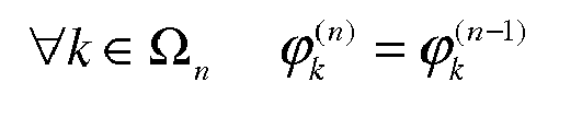
Ω n is the set of nodes in a reception state at the nth iteration, - Ω n is the set of node in a transmission state at the nth iteration,
- Aj are weighing coefficients applied to the extracted synchronization times of the neighboring nodes in a transmission state.
- By definition, the node k has N k neighboring nodes. At the nth iteration of the method, lΩ n,k l neighboring nodes of the node k are in a transmission state and l
Ω n,k l neighboring nodes are in a reception state with Nk =lΩ n,k l + lΩ n,k l - The invention is particularly novel in that each node chooses randomly, for example with equal probability, its state "transmission" or "reception" at each new iteration of the method, and in that the choice of the coefficient Aj take into account this random behavior of the network for ensuring convergence to a situation where all nodes are synchronized altogether. The choice of the coefficients will be discussed in the following description.
- According to a first embodiment of the invention, the new synchronization time


where α(Ω n,k ) is the weight coefficient associated to the actual synchronization time of the considered node k and βj (Ω n,k ) is a weight coefficient associated to the synchronization time of the node j received by the node k. The weights are chosen in order to guarantee a convergence of the system. - For example, a possible choice is

- In this case, the system converges to a mean value plus a mismatch which is different for each node, and mainly depends on the propagation delays of the wireless links arriving at the node k. Thus, the ponderation value is a function of the number of nodes in a transmission state at the n-th iteration, and received by the considered node.
- For a given node, the mismatch is a function of the average of the propagation delays on the communication links between the considered node k and the neighboring nodes. Thus, the mismatch decreases as the number of neighbours increases, or as the distribution of propagation delays is more equal for all nodes. Furthermore, as two neighboring nodes have a similar radio environment, they will tend to the same synchronization time with a good probability. Thus, even if the whole nodes of the system are not perfectly synchronized one with each other, the nodes appear to be synchronized in a given neighborhood.
- The coefficient α(Ω n,k ) can be chosen independently from the propagation delays, and lower than 1. The choice of α(Ω n,k ) impacts the convergence speed of the algorithm. As an option, βj (Ω n,k ) is a function of the path gain between nodes j and k.
- According to a second embodiment of the invention, the method comprises a step of storing the synchronization times of all nodes in a table, the combining
step 44 using the last stored synchronization time of all the neigboring nodes. - By doing this, the algorithm converges more quickly. The table of synchronization times of neighbors contains new and old values Vj for each neighbor. The table also includes the synchronization time Vk of the node itself.
- In this case, the rule for updating the synchronization time


- As discussed above with reference to the first embodiment, without any delay spread for the transmission of signals between nodes, the weights in the linear combination are chosen to ensure the system convergence as a function of the number of neighboring nodes or as a function of the number of transmitting nodes at a given time. However, in a practical system, a delay spread is observed for the propagation of signals between two nodes. With the propagation delay spread, the new time synchronization value is

- Thus, a positive mismatch is added at each iteration of the method which propagates by inference between nodes. If the delay spread values are sufficiently high, a linear drift of all the synchronization values of the nodes (and common to all the nodes) is observed. This means that even if the nodes stay synchronized altogether, the time clock frequency is virtually decreased.
- In order to reduce this issue, during the correcting
step 46, the considered node k learns the slope of the linear drift and corrects its estimated synchronization time by a value
- Finally, the new synchronization time is obtained by

where the


- Furthermore, this tracking also has the advantage of tracking the clock drift due to cheap hardware impairments, in a collaborative fashion, which is particularly useful when nodes are home base stations.
- A fourth embodiment, particularly suitable if some nodes have other means of synchronization as optical fiber networks for example, aims at propagating these reference synchronization information to the other nodes.
- Thus, in this fourth embodiment, the method comprises defining different classes of nodes depending on their type of external synchronization means: none, optical, GPS... and broadcasting these classes along with the synchronization signals dedicated to the nodes.
- According to its class, a node might change its probability of transmission or reception state. For example, for a node being synchronized to a very accurate clock (e.g. GPS), it should not switch into reception mode, and only inject the clock into the mesh wireless network.
- Each node detects if the received synchronization time belongs to one class of nodes and it weights the estimated synchronization time of said neighboring node accordingly. For example, by considering the example of
Figure 1 , wherebase stations BS1 22 andBS2 24 are synchronized by a GPS, a node will consider large weights coefficients if the path gain of the base station to node transmission is large and low weights coefficients if the path gain of the base station to node transmission is low. Thus, nodes that are close to a base station (nodes Figure 1 for example) will be synchronized to the base station, and influence the whole nodes network as an anchor for the synchronization time. At the end, the whole network will be synchronized to the macro network, even nodes out of the coverage of macro cells. - The method of the present invention is implemented in a device for synchronizing nodes comprising means allowing the implementation of the method described above.
- The method and device according to the invention are particularly useful when a propagation delay is observed between the nodes and it is more particularly well suited for applications of home base stations.
Claims (11)
- Method for synchronizing nodes (1, 2, 3, 4, 5, 6, 7, 8, 9, 10, 11, 12, 13) of a mesh wireless network (20), each node transmitting to its neighboring nodes a synchronization signal aligned to a synchronization time dedicated to said node and each node determining its synchronization time based on the synchronization signal, characterized in that it comprises the steps, carried for each node, of:- randomly choosing (32) the state of said node between a transmission and a reception state;- if the chosen state for said node is a transmission state (36), transmitting (38) the synchronization signal to the neighboring nodes;- if the chosen state for said node is a reception state (40) :- receiving (42) the synchronization signals transmitted from the neighboring nodes in a transmission state;- extracting (42) the synchronization times of the neighboring nodes from the received synchronization signals;- combining (44) the synchronization time of said node with the extracted synchronization times of the neighboring nodes; and- updating (48) the synchronization time of said node to be equal to the combining result.
- Method for synchronizing nodes (1, 2, 3, 4, 5, 6, 7, 8, 9, 10, 11, 12, 13) according to claim 1, characterized in that the combining (44) is linear and in that it comprises applying weighting coefficients to the synchronization times of said node and of the neighboring nodes.
- Method for synchronizing nodes (1, 2, 3, 4, 5, 6, 7, 8, 9, 10, 11, 12, 13) according to claim 2, characterized in that the weighting coefficients are function of the number of neighboring nodes in a transmission state.
- Method for synchronizing nodes (1, 2, 3, 4, 5, 6, 7, 8, 9, 10, 11, 12, 13) according to claim 1, characterized in that it comprises a step of storing the synchronization times of all the nodes in a table and in that the combining (44) uses the last stored synchronization times of the neighboring nodes.
- Method for synchronizing nodes (1, 2, 3, 4, 5, 6, 7, 8, 9, 10, 11, 12, 13) according to claim 4, characterized in that the combining comprises summing the last stored synchronization times of the neighboring nodes and dividing the sum result by the number of the neighboring nodes.
- Method for synchronizing nodes (1, 2, 3, 4, 5, 6, 7, 8, 9, 10, 11, 12, 13) according to any one of claims 1 to 5, characterized in that it comprises a step, carried for each node, of correcting (46) the updated synchronization time of said node in order to reduce a synchronization time drift due to propagation delays between nodes.
- Method for synchronizing nodes (1, 2, 3, 4, 5, 6, 7, 8, 9, 10, 11, 12, 13) according to claim 6, characterized in that the correcting step uses a Least Mean Squares adaptive algorithm.
- Method for synchronizing nodes (1, 2, 3, 4, 5, 6, 7, 8, 9, 10, 11, 12, 13) according to any one of claims 1 to 7, characterized in that it comprises a step of defining different classes of nodes, the probability, for each node, to choose a transmission or a reception state being dependent on its own class.
- Method for synchronizing nodes (1, 2, 3, 4, 5, 6, 7, 8, 9, 10, 11, 12, 13) according to claims 1 and 8, characterized in that each node transmits its own class along with the synchronization signal and in that the weighting coefficient applied at each receiving node to the synchronization time of each transmitting node depends on the class of the transmitting node.
- Method for synchronizing nodes (1, 2, 3, 4, 5, 6, 7, 8, 9, 10, 11, 12, 13) according to any one of claims 1 to 9, characterized in that the nodes are home base stations.
- Device for synchronizing nodes (1, 2, 3, 4, 5, 6, 7, 8, 9, 10, 11, 12, 13) of a mesh wireless network (20), each node transmitting to its neighboring nodes a synchronization signal aligned to a synchronization time dedicated to said node and each node determining its synchronization time based on the synchronization signal, characterized in that it comprises means, provided at each node, for:- randomly choosing the state of said node between a transmission and a reception state;- if the chosen state for said node is a transmission state, transmitting the synchronization signal to the neighboring nodes;- if the chosen state for said node is a reception state :- receiving the synchronization signals transmitted from the neighboring nodes in a transmission state;- extracting the synchronization times of the neighboring nodes from the received synchronization signals;- combining the synchronization time of said node with the extracted synchronization times of the neighboring nodes; and- updating the synchronization time of said node to be equal to the combining result.
Priority Applications (2)
| Application Number | Priority Date | Filing Date | Title |
|---|---|---|---|
| EP10305282.5A EP2369880B1 (en) | 2010-03-23 | 2010-03-23 | Method for synchronizing nodes of a mesh wireless network |
| JP2011055505A JP5738632B2 (en) | 2010-03-23 | 2011-03-14 | Method and device for synchronizing nodes of a mesh wireless network |
Applications Claiming Priority (1)
| Application Number | Priority Date | Filing Date | Title |
|---|---|---|---|
| EP10305282.5A EP2369880B1 (en) | 2010-03-23 | 2010-03-23 | Method for synchronizing nodes of a mesh wireless network |
Publications (2)
| Publication Number | Publication Date |
|---|---|
| EP2369880A1 true EP2369880A1 (en) | 2011-09-28 |
| EP2369880B1 EP2369880B1 (en) | 2013-08-21 |
Family
ID=42249743
Family Applications (1)
| Application Number | Title | Priority Date | Filing Date |
|---|---|---|---|
| EP10305282.5A Not-in-force EP2369880B1 (en) | 2010-03-23 | 2010-03-23 | Method for synchronizing nodes of a mesh wireless network |
Country Status (2)
| Country | Link |
|---|---|
| EP (1) | EP2369880B1 (en) |
| JP (1) | JP5738632B2 (en) |
Cited By (5)
| Publication number | Priority date | Publication date | Assignee | Title |
|---|---|---|---|---|
| CN103634895A (en) * | 2013-11-13 | 2014-03-12 | 深圳大学 | Quick beam forming system and carrier synchronization method of each transmitting antenna at source end of quick beam forming system |
| WO2014146435A1 (en) * | 2013-03-18 | 2014-09-25 | 深圳大学 | Distributed beamforming system and carrier synchronization method of transmitting antennas at source end thereof |
| US10820290B2 (en) | 2018-08-13 | 2020-10-27 | At&T Intellectual Property I, L.P. | Over the air synchronization by means of a protocol in a next generation wireless network |
| EP3656071A4 (en) * | 2017-07-20 | 2021-04-21 | Itron Networked Solutions, Inc. | COMPENSATION FOR THE DRIFT OF AN OSCILLATOR IN WIRELESS MESH NETWORKS |
| US11064449B2 (en) | 2019-08-16 | 2021-07-13 | At&T Intellectual Property I, L.P. | Over the air synchronization of network nodes |
Families Citing this family (4)
| Publication number | Priority date | Publication date | Assignee | Title |
|---|---|---|---|---|
| EP2339761B1 (en) * | 2009-12-22 | 2012-07-11 | Mitsubishi Electric R&D Centre Europe B.V. | Method for synchronizing nodes |
| KR101860779B1 (en) | 2011-11-09 | 2018-05-28 | 한국전자통신연구원 | Synchronizing method for mesh node in wireless mesh system |
| CN109525637B (en) * | 2018-10-15 | 2020-04-10 | 北京创鑫旅程网络技术有限公司 | Method and device for determining permanent station |
| EP3813444B1 (en) * | 2019-10-23 | 2025-07-30 | Mitsubishi Electric R&D Centre Europe B.V. | Synchronizing a connected node |
Citations (4)
| Publication number | Priority date | Publication date | Assignee | Title |
|---|---|---|---|---|
| US20050185628A1 (en) * | 2004-02-06 | 2005-08-25 | Sony Corporation | Wireless communication system, wireless communication apparatus and wireless communication method, and computer program |
| US20070014269A1 (en) * | 2005-07-13 | 2007-01-18 | Texas Instruments Incorporated | Apparatus for and method of synchronization and beaconing in a wlan mesh network |
| US7349362B2 (en) * | 2005-06-29 | 2008-03-25 | Meshnetworks, Inc. | Method and system for implementing the time division multiple access method to AD-HOC multihopping wireless networks |
| US20090047913A1 (en) * | 2007-08-15 | 2009-02-19 | Nokia Corporation | Alternate mobile network cell synchronization |
Family Cites Families (5)
| Publication number | Priority date | Publication date | Assignee | Title |
|---|---|---|---|---|
| JP2008187552A (en) * | 2007-01-31 | 2008-08-14 | Hitachi Communication Technologies Ltd | Communication system having inter-base station control channel and base station |
| US8780885B2 (en) * | 2007-07-09 | 2014-07-15 | Qualcomm Incorporated | Synchronization of a peer-to-peer communication network |
| US9253653B2 (en) * | 2007-11-09 | 2016-02-02 | Qualcomm Incorporated | Access point configuration based on received access point signals |
| EP2139168A1 (en) * | 2008-06-25 | 2009-12-30 | Thomson Licensing, Inc. | Method and device for time synchronization in a TDMA multi-hop wireless network |
| EP2339761B1 (en) * | 2009-12-22 | 2012-07-11 | Mitsubishi Electric R&D Centre Europe B.V. | Method for synchronizing nodes |
-
2010
- 2010-03-23 EP EP10305282.5A patent/EP2369880B1/en not_active Not-in-force
-
2011
- 2011-03-14 JP JP2011055505A patent/JP5738632B2/en not_active Expired - Fee Related
Patent Citations (4)
| Publication number | Priority date | Publication date | Assignee | Title |
|---|---|---|---|---|
| US20050185628A1 (en) * | 2004-02-06 | 2005-08-25 | Sony Corporation | Wireless communication system, wireless communication apparatus and wireless communication method, and computer program |
| US7349362B2 (en) * | 2005-06-29 | 2008-03-25 | Meshnetworks, Inc. | Method and system for implementing the time division multiple access method to AD-HOC multihopping wireless networks |
| US20070014269A1 (en) * | 2005-07-13 | 2007-01-18 | Texas Instruments Incorporated | Apparatus for and method of synchronization and beaconing in a wlan mesh network |
| US20090047913A1 (en) * | 2007-08-15 | 2009-02-19 | Nokia Corporation | Alternate mobile network cell synchronization |
Cited By (8)
| Publication number | Priority date | Publication date | Assignee | Title |
|---|---|---|---|---|
| WO2014146435A1 (en) * | 2013-03-18 | 2014-09-25 | 深圳大学 | Distributed beamforming system and carrier synchronization method of transmitting antennas at source end thereof |
| CN103634895A (en) * | 2013-11-13 | 2014-03-12 | 深圳大学 | Quick beam forming system and carrier synchronization method of each transmitting antenna at source end of quick beam forming system |
| WO2015070679A1 (en) * | 2013-11-13 | 2015-05-21 | 深圳大学 | System for quickly synthesizing wave beams and carrier synchronization method for various sending antennas at source end thereof |
| CN103634895B (en) * | 2013-11-13 | 2016-08-17 | 深圳大学 | Fast beam synthesis system and the carrier synchronization method of each transmission antenna of source thereof |
| EP3656071A4 (en) * | 2017-07-20 | 2021-04-21 | Itron Networked Solutions, Inc. | COMPENSATION FOR THE DRIFT OF AN OSCILLATOR IN WIRELESS MESH NETWORKS |
| US10820290B2 (en) | 2018-08-13 | 2020-10-27 | At&T Intellectual Property I, L.P. | Over the air synchronization by means of a protocol in a next generation wireless network |
| US11576135B2 (en) | 2018-08-13 | 2023-02-07 | At&T Intellectual Property I, L.P. | Over the air synchronization by means of a protocol in a next generation wireless network |
| US11064449B2 (en) | 2019-08-16 | 2021-07-13 | At&T Intellectual Property I, L.P. | Over the air synchronization of network nodes |
Also Published As
| Publication number | Publication date |
|---|---|
| EP2369880B1 (en) | 2013-08-21 |
| JP5738632B2 (en) | 2015-06-24 |
| JP2011199864A (en) | 2011-10-06 |
Similar Documents
| Publication | Publication Date | Title |
|---|---|---|
| EP2369880B1 (en) | Method for synchronizing nodes of a mesh wireless network | |
| US9060377B2 (en) | ABS-based method for inter cell interference coordination in LTE-advanced networks | |
| US9307462B2 (en) | Reference signal power measurement and reporting for improving performance in a network with geographically separated antenna ports | |
| EP2541989A1 (en) | Communications system, slave node, route building method, and program | |
| EP2381587B1 (en) | Method and device for determining antenna cooperation set, method and device for determining base station cooperation set | |
| CN115632684B (en) | Transmission strategy design method of perception and communication integrated system | |
| Wang et al. | Cell-free massive MIMO with UAV access points: UAV location optimization | |
| EP2533360A1 (en) | Method and device for antenna calibration | |
| Nallagonda et al. | Censoring-based cooperative spectrum sensing with improved energy detectors and multiple antennas in fading channels | |
| Dong et al. | Optimization-driven DRL-based joint beamformer design for IRS-aided ITSN against smart jamming attacks | |
| JP2012512579A (en) | A cell that builds a wireless communication network | |
| Osorio et al. | Routing in LoRa for smart cities: A gossip study | |
| CN116170060B (en) | A weighted cooperative frequency sensing method for NGSO-GSO downlink communication links | |
| Xie et al. | Intelligent reflecting surface aided wireless clock synchronization for indoor substation | |
| Tourki et al. | Outage analysis of spectrum sharing cognitive DF relay networks using outdated CSI | |
| WO2011143000A1 (en) | Multiple antenna method for reducing inter-cell interference in multi-user wireless systems | |
| Mondal et al. | Primary behaviour‐based energy harvesting multihop cognitive radio network | |
| Mishra et al. | Impact of hardware impairments on TWRN and OWRN AF relaying systems with imperfect channel estimates | |
| Han et al. | Outage probability of multi-hop full-duplex DF relay system over Nakagami-m fading channels | |
| Jin et al. | Evolutionary game theory in multi-objective optimization problem | |
| Moon et al. | Energy-efficient mmWave UDN using distributed multi-agent deep reinforcement learning | |
| Israr et al. | Path loss modeling of WLAN and WiMAX systems | |
| Rathika et al. | Cooperative Communications Based on Deep Learning Using a Recurrent Neural Network in Wireless Communication Networks | |
| KR101488771B1 (en) | Beamforming device and method with channel distribution information and interference temperature level control for MISO interference channel | |
| Le et al. | Implement of multiple access technique by wireless power transfer and relaying network |
Legal Events
| Date | Code | Title | Description |
|---|---|---|---|
| PUAI | Public reference made under article 153(3) epc to a published international application that has entered the european phase |
Free format text: ORIGINAL CODE: 0009012 |
|
| AK | Designated contracting states |
Kind code of ref document: A1 Designated state(s): AT BE BG CH CY CZ DE DK EE ES FI FR GB GR HR HU IE IS IT LI LT LU LV MC MK MT NL NO PL PT RO SE SI SK SM TR |
|
| AX | Request for extension of the european patent |
Extension state: AL BA ME RS |
|
| 17P | Request for examination filed |
Effective date: 20120229 |
|
| 17Q | First examination report despatched |
Effective date: 20120723 |
|
| GRAP | Despatch of communication of intention to grant a patent |
Free format text: ORIGINAL CODE: EPIDOSNIGR1 |
|
| GRAS | Grant fee paid |
Free format text: ORIGINAL CODE: EPIDOSNIGR3 |
|
| GRAA | (expected) grant |
Free format text: ORIGINAL CODE: 0009210 |
|
| AK | Designated contracting states |
Kind code of ref document: B1 Designated state(s): AT BE BG CH CY CZ DE DK EE ES FI FR GB GR HR HU IE IS IT LI LT LU LV MC MK MT NL NO PL PT RO SE SI SK SM TR |
|
| REG | Reference to a national code |
Ref country code: GB Ref legal event code: FG4D |
|
| REG | Reference to a national code |
Ref country code: CH Ref legal event code: EP |
|
| REG | Reference to a national code |
Ref country code: AT Ref legal event code: REF Ref document number: 628720 Country of ref document: AT Kind code of ref document: T Effective date: 20130915 |
|
| REG | Reference to a national code |
Ref country code: IE Ref legal event code: FG4D |
|
| REG | Reference to a national code |
Ref country code: DE Ref legal event code: R096 Ref document number: 602010009616 Country of ref document: DE Effective date: 20131017 |
|
| REG | Reference to a national code |
Ref country code: AT Ref legal event code: MK05 Ref document number: 628720 Country of ref document: AT Kind code of ref document: T Effective date: 20130821 Ref country code: NL Ref legal event code: VDEP Effective date: 20130821 |
|
| REG | Reference to a national code |
Ref country code: LT Ref legal event code: MG4D |
|
| PG25 | Lapsed in a contracting state [announced via postgrant information from national office to epo] |
Ref country code: PT Free format text: LAPSE BECAUSE OF FAILURE TO SUBMIT A TRANSLATION OF THE DESCRIPTION OR TO PAY THE FEE WITHIN THE PRESCRIBED TIME-LIMIT Effective date: 20131223 Ref country code: SE Free format text: LAPSE BECAUSE OF FAILURE TO SUBMIT A TRANSLATION OF THE DESCRIPTION OR TO PAY THE FEE WITHIN THE PRESCRIBED TIME-LIMIT Effective date: 20130821 Ref country code: LT Free format text: LAPSE BECAUSE OF FAILURE TO SUBMIT A TRANSLATION OF THE DESCRIPTION OR TO PAY THE FEE WITHIN THE PRESCRIBED TIME-LIMIT Effective date: 20130821 Ref country code: AT Free format text: LAPSE BECAUSE OF FAILURE TO SUBMIT A TRANSLATION OF THE DESCRIPTION OR TO PAY THE FEE WITHIN THE PRESCRIBED TIME-LIMIT Effective date: 20130821 Ref country code: IS Free format text: LAPSE BECAUSE OF FAILURE TO SUBMIT A TRANSLATION OF THE DESCRIPTION OR TO PAY THE FEE WITHIN THE PRESCRIBED TIME-LIMIT Effective date: 20131221 Ref country code: HR Free format text: LAPSE BECAUSE OF FAILURE TO SUBMIT A TRANSLATION OF THE DESCRIPTION OR TO PAY THE FEE WITHIN THE PRESCRIBED TIME-LIMIT Effective date: 20130821 Ref country code: CY Free format text: LAPSE BECAUSE OF FAILURE TO SUBMIT A TRANSLATION OF THE DESCRIPTION OR TO PAY THE FEE WITHIN THE PRESCRIBED TIME-LIMIT Effective date: 20130619 Ref country code: NO Free format text: LAPSE BECAUSE OF FAILURE TO SUBMIT A TRANSLATION OF THE DESCRIPTION OR TO PAY THE FEE WITHIN THE PRESCRIBED TIME-LIMIT Effective date: 20131121 |
|
| PG25 | Lapsed in a contracting state [announced via postgrant information from national office to epo] |
Ref country code: BE Free format text: LAPSE BECAUSE OF FAILURE TO SUBMIT A TRANSLATION OF THE DESCRIPTION OR TO PAY THE FEE WITHIN THE PRESCRIBED TIME-LIMIT Effective date: 20130821 Ref country code: SI Free format text: LAPSE BECAUSE OF FAILURE TO SUBMIT A TRANSLATION OF THE DESCRIPTION OR TO PAY THE FEE WITHIN THE PRESCRIBED TIME-LIMIT Effective date: 20130821 Ref country code: LV Free format text: LAPSE BECAUSE OF FAILURE TO SUBMIT A TRANSLATION OF THE DESCRIPTION OR TO PAY THE FEE WITHIN THE PRESCRIBED TIME-LIMIT Effective date: 20130821 Ref country code: FI Free format text: LAPSE BECAUSE OF FAILURE TO SUBMIT A TRANSLATION OF THE DESCRIPTION OR TO PAY THE FEE WITHIN THE PRESCRIBED TIME-LIMIT Effective date: 20130821 Ref country code: PL Free format text: LAPSE BECAUSE OF FAILURE TO SUBMIT A TRANSLATION OF THE DESCRIPTION OR TO PAY THE FEE WITHIN THE PRESCRIBED TIME-LIMIT Effective date: 20130821 Ref country code: GR Free format text: LAPSE BECAUSE OF FAILURE TO SUBMIT A TRANSLATION OF THE DESCRIPTION OR TO PAY THE FEE WITHIN THE PRESCRIBED TIME-LIMIT Effective date: 20131122 |
|
| PG25 | Lapsed in a contracting state [announced via postgrant information from national office to epo] |
Ref country code: CY Free format text: LAPSE BECAUSE OF FAILURE TO SUBMIT A TRANSLATION OF THE DESCRIPTION OR TO PAY THE FEE WITHIN THE PRESCRIBED TIME-LIMIT Effective date: 20130821 |
|
| PG25 | Lapsed in a contracting state [announced via postgrant information from national office to epo] |
Ref country code: SK Free format text: LAPSE BECAUSE OF FAILURE TO SUBMIT A TRANSLATION OF THE DESCRIPTION OR TO PAY THE FEE WITHIN THE PRESCRIBED TIME-LIMIT Effective date: 20130821 Ref country code: RO Free format text: LAPSE BECAUSE OF FAILURE TO SUBMIT A TRANSLATION OF THE DESCRIPTION OR TO PAY THE FEE WITHIN THE PRESCRIBED TIME-LIMIT Effective date: 20130821 Ref country code: NL Free format text: LAPSE BECAUSE OF FAILURE TO SUBMIT A TRANSLATION OF THE DESCRIPTION OR TO PAY THE FEE WITHIN THE PRESCRIBED TIME-LIMIT Effective date: 20130821 Ref country code: EE Free format text: LAPSE BECAUSE OF FAILURE TO SUBMIT A TRANSLATION OF THE DESCRIPTION OR TO PAY THE FEE WITHIN THE PRESCRIBED TIME-LIMIT Effective date: 20130821 Ref country code: CZ Free format text: LAPSE BECAUSE OF FAILURE TO SUBMIT A TRANSLATION OF THE DESCRIPTION OR TO PAY THE FEE WITHIN THE PRESCRIBED TIME-LIMIT Effective date: 20130821 Ref country code: DK Free format text: LAPSE BECAUSE OF FAILURE TO SUBMIT A TRANSLATION OF THE DESCRIPTION OR TO PAY THE FEE WITHIN THE PRESCRIBED TIME-LIMIT Effective date: 20130821 |
|
| PG25 | Lapsed in a contracting state [announced via postgrant information from national office to epo] |
Ref country code: IT Free format text: LAPSE BECAUSE OF FAILURE TO SUBMIT A TRANSLATION OF THE DESCRIPTION OR TO PAY THE FEE WITHIN THE PRESCRIBED TIME-LIMIT Effective date: 20130821 Ref country code: ES Free format text: LAPSE BECAUSE OF FAILURE TO SUBMIT A TRANSLATION OF THE DESCRIPTION OR TO PAY THE FEE WITHIN THE PRESCRIBED TIME-LIMIT Effective date: 20130821 |
|
| PLBE | No opposition filed within time limit |
Free format text: ORIGINAL CODE: 0009261 |
|
| STAA | Information on the status of an ep patent application or granted ep patent |
Free format text: STATUS: NO OPPOSITION FILED WITHIN TIME LIMIT |
|
| 26N | No opposition filed |
Effective date: 20140522 |
|
| REG | Reference to a national code |
Ref country code: DE Ref legal event code: R097 Ref document number: 602010009616 Country of ref document: DE Effective date: 20140522 |
|
| PG25 | Lapsed in a contracting state [announced via postgrant information from national office to epo] |
Ref country code: LU Free format text: LAPSE BECAUSE OF FAILURE TO SUBMIT A TRANSLATION OF THE DESCRIPTION OR TO PAY THE FEE WITHIN THE PRESCRIBED TIME-LIMIT Effective date: 20140323 |
|
| REG | Reference to a national code |
Ref country code: CH Ref legal event code: PL |
|
| REG | Reference to a national code |
Ref country code: IE Ref legal event code: MM4A |
|
| PG25 | Lapsed in a contracting state [announced via postgrant information from national office to epo] |
Ref country code: LI Free format text: LAPSE BECAUSE OF NON-PAYMENT OF DUE FEES Effective date: 20140331 Ref country code: CH Free format text: LAPSE BECAUSE OF NON-PAYMENT OF DUE FEES Effective date: 20140331 Ref country code: IE Free format text: LAPSE BECAUSE OF NON-PAYMENT OF DUE FEES Effective date: 20140323 |
|
| REG | Reference to a national code |
Ref country code: FR Ref legal event code: PLFP Year of fee payment: 7 |
|
| PG25 | Lapsed in a contracting state [announced via postgrant information from national office to epo] |
Ref country code: MT Free format text: LAPSE BECAUSE OF FAILURE TO SUBMIT A TRANSLATION OF THE DESCRIPTION OR TO PAY THE FEE WITHIN THE PRESCRIBED TIME-LIMIT Effective date: 20130821 |
|
| PG25 | Lapsed in a contracting state [announced via postgrant information from national office to epo] |
Ref country code: SM Free format text: LAPSE BECAUSE OF FAILURE TO SUBMIT A TRANSLATION OF THE DESCRIPTION OR TO PAY THE FEE WITHIN THE PRESCRIBED TIME-LIMIT Effective date: 20130821 |
|
| PG25 | Lapsed in a contracting state [announced via postgrant information from national office to epo] |
Ref country code: MC Free format text: LAPSE BECAUSE OF FAILURE TO SUBMIT A TRANSLATION OF THE DESCRIPTION OR TO PAY THE FEE WITHIN THE PRESCRIBED TIME-LIMIT Effective date: 20130821 |
|
| PG25 | Lapsed in a contracting state [announced via postgrant information from national office to epo] |
Ref country code: BG Free format text: LAPSE BECAUSE OF FAILURE TO SUBMIT A TRANSLATION OF THE DESCRIPTION OR TO PAY THE FEE WITHIN THE PRESCRIBED TIME-LIMIT Effective date: 20130821 |
|
| PG25 | Lapsed in a contracting state [announced via postgrant information from national office to epo] |
Ref country code: HU Free format text: LAPSE BECAUSE OF FAILURE TO SUBMIT A TRANSLATION OF THE DESCRIPTION OR TO PAY THE FEE WITHIN THE PRESCRIBED TIME-LIMIT; INVALID AB INITIO Effective date: 20100323 Ref country code: TR Free format text: LAPSE BECAUSE OF FAILURE TO SUBMIT A TRANSLATION OF THE DESCRIPTION OR TO PAY THE FEE WITHIN THE PRESCRIBED TIME-LIMIT Effective date: 20130821 |
|
| REG | Reference to a national code |
Ref country code: FR Ref legal event code: PLFP Year of fee payment: 8 |
|
| REG | Reference to a national code |
Ref country code: FR Ref legal event code: PLFP Year of fee payment: 9 |
|
| REG | Reference to a national code |
Ref country code: DE Ref legal event code: R082 Ref document number: 602010009616 Country of ref document: DE Representative=s name: LAVOIX MUNICH, DE |
|
| PG25 | Lapsed in a contracting state [announced via postgrant information from national office to epo] |
Ref country code: MK Free format text: LAPSE BECAUSE OF FAILURE TO SUBMIT A TRANSLATION OF THE DESCRIPTION OR TO PAY THE FEE WITHIN THE PRESCRIBED TIME-LIMIT Effective date: 20130821 |
|
| PGFP | Annual fee paid to national office [announced via postgrant information from national office to epo] |
Ref country code: GB Payment date: 20200323 Year of fee payment: 11 Ref country code: DE Payment date: 20200311 Year of fee payment: 11 |
|
| PGFP | Annual fee paid to national office [announced via postgrant information from national office to epo] |
Ref country code: FR Payment date: 20200225 Year of fee payment: 11 |
|
| REG | Reference to a national code |
Ref country code: DE Ref legal event code: R119 Ref document number: 602010009616 Country of ref document: DE |
|
| GBPC | Gb: european patent ceased through non-payment of renewal fee |
Effective date: 20210323 |
|
| PG25 | Lapsed in a contracting state [announced via postgrant information from national office to epo] |
Ref country code: DE Free format text: LAPSE BECAUSE OF NON-PAYMENT OF DUE FEES Effective date: 20211001 Ref country code: GB Free format text: LAPSE BECAUSE OF NON-PAYMENT OF DUE FEES Effective date: 20210323 Ref country code: FR Free format text: LAPSE BECAUSE OF NON-PAYMENT OF DUE FEES Effective date: 20210331 |