EP2369479A2 - Procédés et systèmes pour fournir un accès à un environnement informatique - Google Patents
Procédés et systèmes pour fournir un accès à un environnement informatique Download PDFInfo
- Publication number
- EP2369479A2 EP2369479A2 EP11161963A EP11161963A EP2369479A2 EP 2369479 A2 EP2369479 A2 EP 2369479A2 EP 11161963 A EP11161963 A EP 11161963A EP 11161963 A EP11161963 A EP 11161963A EP 2369479 A2 EP2369479 A2 EP 2369479A2
- Authority
- EP
- European Patent Office
- Prior art keywords
- machine
- client
- virtual machine
- resource
- computing device
- Prior art date
- Legal status (The legal status is an assumption and is not a legal conclusion. Google has not performed a legal analysis and makes no representation as to the accuracy of the status listed.)
- Ceased
Links
Images


Classifications
-
- G—PHYSICS
- G06—COMPUTING; CALCULATING OR COUNTING
- G06F—ELECTRIC DIGITAL DATA PROCESSING
- G06F9/00—Arrangements for program control, e.g. control units
- G06F9/06—Arrangements for program control, e.g. control units using stored programs, i.e. using an internal store of processing equipment to receive or retain programs
- G06F9/46—Multiprogramming arrangements
- G06F9/50—Allocation of resources, e.g. of the central processing unit [CPU]
- G06F9/5005—Allocation of resources, e.g. of the central processing unit [CPU] to service a request
-
- G—PHYSICS
- G06—COMPUTING; CALCULATING OR COUNTING
- G06F—ELECTRIC DIGITAL DATA PROCESSING
- G06F21/00—Security arrangements for protecting computers, components thereof, programs or data against unauthorised activity
- G06F21/50—Monitoring users, programs or devices to maintain the integrity of platforms, e.g. of processors, firmware or operating systems
- G06F21/52—Monitoring users, programs or devices to maintain the integrity of platforms, e.g. of processors, firmware or operating systems during program execution, e.g. stack integrity ; Preventing unwanted data erasure; Buffer overflow
- G06F21/53—Monitoring users, programs or devices to maintain the integrity of platforms, e.g. of processors, firmware or operating systems during program execution, e.g. stack integrity ; Preventing unwanted data erasure; Buffer overflow by executing in a restricted environment, e.g. sandbox or secure virtual machine
-
- G—PHYSICS
- G06—COMPUTING; CALCULATING OR COUNTING
- G06F—ELECTRIC DIGITAL DATA PROCESSING
- G06F9/00—Arrangements for program control, e.g. control units
- G06F9/06—Arrangements for program control, e.g. control units using stored programs, i.e. using an internal store of processing equipment to receive or retain programs
- G06F9/44—Arrangements for executing specific programs
- G06F9/455—Emulation; Interpretation; Software simulation, e.g. virtualisation or emulation of application or operating system execution engines
- G06F9/45533—Hypervisors; Virtual machine monitors
- G06F9/45558—Hypervisor-specific management and integration aspects
-
- G—PHYSICS
- G06—COMPUTING; CALCULATING OR COUNTING
- G06F—ELECTRIC DIGITAL DATA PROCESSING
- G06F9/00—Arrangements for program control, e.g. control units
- G06F9/06—Arrangements for program control, e.g. control units using stored programs, i.e. using an internal store of processing equipment to receive or retain programs
- G06F9/46—Multiprogramming arrangements
- G06F9/50—Allocation of resources, e.g. of the central processing unit [CPU]
- G06F9/5061—Partitioning or combining of resources
- G06F9/5077—Logical partitioning of resources; Management or configuration of virtualized resources
-
- G—PHYSICS
- G06—COMPUTING; CALCULATING OR COUNTING
- G06F—ELECTRIC DIGITAL DATA PROCESSING
- G06F9/00—Arrangements for program control, e.g. control units
- G06F9/06—Arrangements for program control, e.g. control units using stored programs, i.e. using an internal store of processing equipment to receive or retain programs
- G06F9/46—Multiprogramming arrangements
- G06F9/54—Interprogram communication
-
- H—ELECTRICITY
- H04—ELECTRIC COMMUNICATION TECHNIQUE
- H04L—TRANSMISSION OF DIGITAL INFORMATION, e.g. TELEGRAPHIC COMMUNICATION
- H04L63/00—Network architectures or network communication protocols for network security
- H04L63/10—Network architectures or network communication protocols for network security for controlling access to devices or network resources
-
- H—ELECTRICITY
- H04—ELECTRIC COMMUNICATION TECHNIQUE
- H04L—TRANSMISSION OF DIGITAL INFORMATION, e.g. TELEGRAPHIC COMMUNICATION
- H04L67/00—Network arrangements or protocols for supporting network services or applications
- H04L67/50—Network services
- H04L67/56—Provisioning of proxy services
- H04L67/562—Brokering proxy services
-
- G—PHYSICS
- G06—COMPUTING; CALCULATING OR COUNTING
- G06F—ELECTRIC DIGITAL DATA PROCESSING
- G06F9/00—Arrangements for program control, e.g. control units
- G06F9/06—Arrangements for program control, e.g. control units using stored programs, i.e. using an internal store of processing equipment to receive or retain programs
- G06F9/44—Arrangements for executing specific programs
- G06F9/455—Emulation; Interpretation; Software simulation, e.g. virtualisation or emulation of application or operating system execution engines
- G06F9/45533—Hypervisors; Virtual machine monitors
- G06F9/45558—Hypervisor-specific management and integration aspects
- G06F2009/45562—Creating, deleting, cloning virtual machine instances
-
- G—PHYSICS
- G06—COMPUTING; CALCULATING OR COUNTING
- G06F—ELECTRIC DIGITAL DATA PROCESSING
- G06F9/00—Arrangements for program control, e.g. control units
- G06F9/06—Arrangements for program control, e.g. control units using stored programs, i.e. using an internal store of processing equipment to receive or retain programs
- G06F9/44—Arrangements for executing specific programs
- G06F9/455—Emulation; Interpretation; Software simulation, e.g. virtualisation or emulation of application or operating system execution engines
- G06F9/45533—Hypervisors; Virtual machine monitors
- G06F9/45558—Hypervisor-specific management and integration aspects
- G06F2009/4557—Distribution of virtual machine instances; Migration and load balancing
-
- G—PHYSICS
- G06—COMPUTING; CALCULATING OR COUNTING
- G06F—ELECTRIC DIGITAL DATA PROCESSING
- G06F9/00—Arrangements for program control, e.g. control units
- G06F9/06—Arrangements for program control, e.g. control units using stored programs, i.e. using an internal store of processing equipment to receive or retain programs
- G06F9/44—Arrangements for executing specific programs
- G06F9/455—Emulation; Interpretation; Software simulation, e.g. virtualisation or emulation of application or operating system execution engines
- G06F9/45533—Hypervisors; Virtual machine monitors
- G06F9/45558—Hypervisor-specific management and integration aspects
- G06F2009/45575—Starting, stopping, suspending or resuming virtual machine instances
-
- G—PHYSICS
- G06—COMPUTING; CALCULATING OR COUNTING
- G06F—ELECTRIC DIGITAL DATA PROCESSING
- G06F2209/00—Indexing scheme relating to G06F9/00
- G06F2209/54—Indexing scheme relating to G06F9/54
- G06F2209/541—Client-server
-
- G—PHYSICS
- G06—COMPUTING; CALCULATING OR COUNTING
- G06F—ELECTRIC DIGITAL DATA PROCESSING
- G06F2221/00—Indexing scheme relating to security arrangements for protecting computers, components thereof, programs or data against unauthorised activity
- G06F2221/21—Indexing scheme relating to G06F21/00 and subgroups addressing additional information or applications relating to security arrangements for protecting computers, components thereof, programs or data against unauthorised activity
- G06F2221/2141—Access rights, e.g. capability lists, access control lists, access tables, access matrices
-
- G—PHYSICS
- G06—COMPUTING; CALCULATING OR COUNTING
- G06F—ELECTRIC DIGITAL DATA PROCESSING
- G06F2221/00—Indexing scheme relating to security arrangements for protecting computers, components thereof, programs or data against unauthorised activity
- G06F2221/21—Indexing scheme relating to G06F21/00 and subgroups addressing additional information or applications relating to security arrangements for protecting computers, components thereof, programs or data against unauthorised activity
- G06F2221/2149—Restricted operating environment
Definitions
- the invention generally relates to providing access to computing environments. More particularly, the invention relates to methods and systems for establishing a connection between a client system and a virtual machine.
- Desktop deployment strategies such as personal desktop deployment or server-based computing deployment strategies, suffer from drawbacks.
- Conventional desktop PC deployment strategies create significant problems with management, upgrade cycles and support requirements that directly translate into a high total cost of ownership.
- Each desktop PC is installed on the user's desktop, and any hardware maintenance typically requires IT personnel to come to the user's desk. Additionally, PCs age rapidly and are usually replaced on a recurring basis as the hardware becomes dated and/or obsolete. Remote access and distributed, multi-office deployments may amplify these problems.
- a server-based computing model solves many of the desktop PC deployment model problems, but at the expense of a less flexible environment.
- each server hosts a number of users and applications, meaning that one user or application may affect the performance perceived by other users served by the same server.
- the performance issue associated with thin clients may result in enterprises using server-based computing only for specific niche applications, such as remote access applications.
- the deployment strategy of combining the desktop PC and the thin client/server-based computing model is subject to these same limitations as each PC still needs to be managed, and the operating system and software may still need to be patched and updated. It would be desirable to provide a system having a lower total cost of ownership of traditional server-based computing systems while avoiding the performance degradation those systems can suffer.
- An array of inexpensive physical machines may be partitioned into multiple virtual machines, creating a virtual PC for each user.
- the physical machines may be servers such as rack-mount servers, blade servers, or stand-alone servers.
- the physical machines may also be workstations or workstation blades or personal computers.
- a policy-based dynamic deployment system provisions the virtual machines and associates the virtual machine with an execution machine (i.e., a physical machine) and a user.
- Centralized hosting provides the manageability of server-based computing while the dedicated environment provides the flexibility and compatibility with applications that a desktop PC enables.
- the system has a much lower total cost of ownership - because the system is implemented in software, rather than being dependent on hardware, the system has a much lower total cost of ownership.
- the hardware lifecycle may be extended by increasing the amount of hardware resources assigned to virtual machines as computational demands increase over time. Additionally, the use of virtualization eases the difficulty in dealing with multiple OS images.
- machines are configured to run multiple copies of one or more operating systems (e.g. different versions/releases of WINDOWS from Microsoft Corporation).
- Users transmit requests for access to computing resources to the deployment system, which may use a configuration policy to decide how (with what physical and/or virtual resources) and where (on which physical machine in the machine farm and on which virtual machine) to provide access to the requested computing resource.
- the virtual machine can be created on demand, and the requested software resource may be downloaded and installed in the virtual machine as required.
- the virtual machine may be pre-configured with a plurality of software and/or virtual hardware resources to provide a particular computing environment to the user.
- the user request is directed to the selected, configured virtual machine and a remote display connection is established between the virtual machine and a remote display client on the user's access device, which will be referred to generally as a "client machine.”
- client machine Devices such as CD-ROM drives, floppy drives, USB drives and other similar devices that are connected to the client machine are connected and remotely accessible to the virtual machine, thereby allowing the use of these devices in a manner similar to a standard desktop computer.
- a deployment system may manage a pool of virtual machines (a machine farm) to which new virtual machines can be added on demand.
- a plurality of software modules including a session management component and a virtual machine management component may provide management functionality.
- Executing virtual machines may be migrated from one physical machine to another, under control of the deployment system, to provide load balancing or to facilitate hardware maintenance.
- Inactive virtual machines may be suspended to free physical computing resources.
- Active virtual machines may be migrated from one physical machine to another to consolidate them onto a smaller number of physical machines to allow the unused physical machines to be shutdown to save power during off-peak periods or to free the physical resource to be re-assigned for a different purpose e.g. process web requests.
- Suspended virtual machines may be resumed prior to users requiring access. This can be done manually or automatically via policies or preferences or through a learning process by monitoring a user's behavior over time.
- Performance requirements of the requested resource may be considered when allocating computing resources to virtual machines.
- a financial analysis package may require twice as many CPU resources as a generic productivity application, such as those included in MICROSOFT OFFICE, manufactured by Microsoft Corporation of Redmond, Washington.
- a virtual machine providing the financial analysis package may execute on a physical machine determined to have sufficient spare computational capacity, or existing virtual machines may be relocated to other available physical machines to ensure sufficient available capacity on a particular physical machine.
- Each user is provided a separate virtual machine environment, which provides increased flexibility in that each user may run any version or configuration of an operating system independently of other users and also allows users to run potentially dangerous or destabilizing applications with little risk of affecting other users. This is particularly useful for developers/testers/information technology personnel who frequently need to re-install and modify the operating system and run potentially destabilizing applications.
- Virtual machines Since sharing computing resources and CPU scheduling occurs outside of the virtual machine environment, users can run computing-resource intensive resources with no risk of affecting other users. Virtual machines also provide increased security isolation between users. Because each user is running a separate copy of the OS, there is much less chance of security breaches and virus infections over the between-users boundaries than in the shared OS case.
- a solution is also provided for problems that arise from a situation where, in a hardware-based system of machines, the hardware is mixed, whether due to an initial purchasing decision or due to the acquisition of different types of physical machines over time. Even if initially all of the hardware was uniform, purchasing additional hardware to replace failing modules and increasing the capacity typically leads to non-uniform hardware throughout a machine farm. Even if all hardware is purchased from the same vendor, it is likely that the hardware purchased later will use different chipsets and components, and will require different drivers.
- Non-uniform hardware has traditionally translated into the need to maintain multiple versions of the operating system images (which means higher costs) and limits flexibility of moving users between machines - because the operating system image may be incompatible - which also translates into higher cost. Virtual machines allow efficient use of the same operating system image even in a hardware farm that includes heterogeneous machines. The use of the same operating system image helps to significantly reduce the management cost.
- Adding remote display capability e.g. presentation layer protocols, such as ICA, RDP, or X11
- virtualization techniques allows virtualization to be used for interactive computing.
- Hosting multiple virtual machines on an execution machine allows better utilization of the available physical computing resources (e.g.: space, power, processing power, processing capacity, RAM, bandwidth, etc.) thereby lowering costs.
- the use of virtualization also allows hardware to be updated and maintained independently of OS version and specific device drivers hosted in the operating systems or virtual machines. Additionally, virtual machines enhance system security by isolating computing environments from each other.
- a method for providing access to a computing environment includes the step of receiving, by a broker machine, a request from a client machine for access to a computing environment, the request including an identification of a user of the client machine.
- One of a plurality of virtual machines is identified, the identified virtual machine providing the requested computing environment.
- One of a plurality of execution machines is identified, the identified execution machine executing a hypervisor providing access to hardware resources required by the identified virtual machine.
- a connection is established between the client machine and the identified virtual machine.
- one of the plurality of virtual machines is identified responsive to the received identification of the user of the client machine.
- the one of the plurality of execution machines is identified responsive to an identification of hardware resources required by the identified virtual machine.
- the identified virtual machine is launched in the hypervisor.
- a connection is established between the client machine and the identified virtual machine using a presentation layer protocol.
- an apparatus in a system providing access to a computing environment by a broker machine to a client machine, an execution machine executing a hypervisor providing access to hardware resources required by the computing environment, an apparatus comprises an identification component, an execution component, and a management component.
- the identification component is in communication with a virtual machine management component and receives an identification of one of a plurality of virtual machines, the identified virtual machine providing a requested computing environment.
- the execution component provisions the identified virtual machine.
- the management component establishes a connection between the client machine and the identified virtual machine.
- a virtual machine service component executing in the hypervisor is in communication with the session management component and receives configuration information associated with the client machine.
- the virtual machine service component executes in the identified virtual machine.
- the identification component receives from the broker machine an identification of one of a plurality of execution machines.
- comprises a transceiver receiving an identification by a user of the client machine of a type of computing environment requested and transmitting the identification of the type of computing environment requested to the virtual machine management component.
- the virtual machine management component allocates the identified virtual machine to a user.
- the management component further comprises providing an internet protocol address associated with the identified virtual machine to the client machine.
- the management component further comprises providing an internet protocol address associated with the execution machine to the client machine.
- the management component establishes a connection between the client machine and the virtual machine using a presentation layer protocol.
- FIG. 1 a block diagram of one embodiment of an environment in which a client machine 10, 10' accesses a computing resource provided by a remote machine, 30, 30', 30", 30"' is shown.
- a remote machine 30 such as remote machine 30, 30', 30", or 30"' (hereafter referred to generally as remote machine 30) accepts connections from a user of a client machine 10.
- the system may provide multiple ones of any or each of those components.
- the system may include multiple, logically-grouped remote machines 30, one or more of which is available to provide a client machine 10, 10' access to computing resources.
- the logical group of remote machines may be referred to as a "server farm" or “machine farm,” indicated in FIG. 1A as machine farm 38.
- the remote machines 30 may be geographically dispersed.
- the group of remote machines 30 logically grouped as a machine farm 38 may be interconnected using a wide-area network (WAN) connection, metropolitan-area network (MAN) connection, a local area network (LAN) a storage-area network (SAN), or a public network such as the Internet.
- a machine farm 38 may include remote machines 30 physically located in geographically diverse locations around the world, including different continents, regions of a continent, countries, regions of a country, states, regions of a state, cities, regions of a city, campuses, regions of a campus, or rooms. Data transmission speeds between remote machines 30 in the machine farm 38 can be increased if the remote machines 30 are connected using a local-area network (LAN) connection or some form of direct connection.
- a machine farm 38 may be administered as a single entity.
- a centralized service may provide management for machine farm 38.
- one or more remote machines 30 elect a particular remote machine 30 to provide management functionality for the farm.
- the elected remote machine 30 may be referred to as a management server, management node, or management process.
- the management node 30 may gather and store information about a plurality of remote machines 30, respond to requests for access to resources hosted by remote machines 30, and enable the establishment of connections between client machines 10 and remote machines 30.
- an administrator designates one or more remote machines 30 to provide management functionality for machine farm 38.
- management of the machine farm 38 may be de-centralized.
- one or more remote machines 30 comprise components, subsystems and modules to support one or more management services for the machine farm 38.
- one or more remote machines 30 provide functionality for management of dynamic data, including techniques for handling failover, data replication, and increasing the robustness of the machine farm 38.
- one or more remote machines 30 include communications capabilities to enable the one or more remote machines 30 to interact with one another to share responsibility for management tasks.
- Each remote machine 30 may communicate with a persistent store and, in some embodiments, with a dynamic store.
- Persistent store may be physically implemented on a disk, disk farm, a redundant array of independent disks (RAID), writeable compact disc, or any other device that allows data to be read and written and that maintains written data if power is removed from the storage device.
- a single physical device may provide storage for a plurality of persistent stores, i.e., a single physical device may be used to provide the persistent store for more than one machine farm 38.
- the persistent store maintains static data associated with each remote machine 30 in machine farm 38 and global data used by all remote machines 30 within the machine farm 38.
- the persistent store may maintain the server data in a Lightweight Directory Access Protocol (LDAP) data model.
- LDAP Lightweight Directory Access Protocol
- the persistent store stores server data in an ODBC-compliant database.
- static data refers to data that do not change frequently, i.e., data that change only on an hourly, daily, or weekly basis, or data that never change.
- the data stored by the persistent store may be replicated for reliability purposes physically or logically.
- physical redundancy may be provided using a set of redundant, mirrored disks, each providing a copy of the data.
- the database itself may be replicated using standard database techniques to provide multiple copies of the database.
- both physical and logical replication may be used concurrently.
- the remote machines 30 store "static" data, i.e., data that persist across client sessions, in the persistent store. Writing to the persistent store can take relatively long periods of time. To minimize accesses to the persistent store, the remote machines 30 may develop a logical, common database (i.e., the dynamic store) that is accessible by all of the remote machines 30in the machine farm 38 for accessing and storing some types of data.
- the dynamic store may be physically implemented in the local memory of a single or multiple remote machines 30in the machine farm 38.
- the local memory can be random access memory, disk, disk farm, a redundant array of independent disks (RAID), or any other memory device that allows data to be read and written.
- runtime data data stored in the dynamic store are data that are typically queried or changed frequently during runtime.
- runtime data examples of such data (hereafter referred to as runtime data) are the current workload level for each of the remote machines 30in the machine farm 38, the status of the remote machines 30 in the machine farm 38, client session data, the number of virtual machines supported by a remote machine 30, the identity of the operating systems supported by a remote machine 30, and licensing information.
- the dynamic store comprises one or more tables, each of which stores records of attribute-value pairs. Any number of tables may exist, but each table stores records of only one type. Tables are, in some embodiments identified by name. Thus, in this embodiment, two remote machines 30 that use the same name to open a table refer to the same logical table.
- the dynamic store (i.e., the collection of all record tables) can be embodied in various ways.
- the dynamic store is centralized; that is, all runtime data are stored in the memory of one remote machine 30 in the machine farm 38. That server operates in a manner similar to the management node described above, that is, all other remote machines 30 in the machine farm 38 communicate with the server acting as the centralized data store when seeking access to that runtime data.
- each remote machine 30 in the machine farm 38 keeps a full copy of the dynamic store.
- each remote machine 30 communicates with every other remote machine 30 to keep its copy of the dynamic store up to date.
- each remote machine 30 maintains its own runtime data and communicates with every other remote machine 30 when seeking to obtain runtime data from them.
- a remote machine 30 attempting to find an application program requested by the client machine 10 may communicate directly with every other remote machine 30 in the machine farm 38 to find one or more servers hosting the requested application.
- a collector point is a server that collects run-time data.
- Each collector point stores runtime data collected from certain other remote machines 30in the machine farm 38.
- Each remote machine 30 in the machine farm 38 is capable of operating as, and consequently is capable of being designated as, a collector point.
- each collector point stores a copy of the entire dynamic store.
- each collector point stores a portion of the dynamic store, i.e., it maintains runtime data of a particular data type.
- the type of data stored by a remote machine 30 may be predetermined according to one or more criteria. For example, remote machines 30may store different types of data based on their boot order. Alternatively, the type of data stored by a remote machine 30 may be configured by an administrator using administration tool 140. In these embodiments, the dynamic store is distributed among two or more remote machines 30in the machine farm 38.
- Remote machines 30 not designated as collector points know the remote machines 30 in a machine farm 38 that are designated as collector points.
- a remote machine 30 not designated as a collector point communicates with a particular collector point when delivering and requesting runtime data. Consequently, collector points lighten network traffic because each remote machine 30 in the machine farm 38 communicates with a single collector point remote machine 30, rather than with every other remote machine 30, when seeking to access the runtime data.
- the machine farm 38 can be heterogeneous, that is, one or more of the remote machines 30 can operate according to one type of operating system platform (e.g., WINDOWS NT, manufactured by Microsoft Corp. of Redmond, Washington), while one or more of the other remote machines 30 can operate according to another type of operating system platform (e.g., Unix or Linux). Additionally, a heterogeneous machine farm 38 may include one or more remote machines 30 operating according to a type of operating system, while one or more other remote machines 30 execute one or more types of hypervisors rather than operating systems. In these embodiments, hypervisors may be used to emulate virtual hardware, partition physical hardware, virtualize physical hardware, and execute virtual machines that provide access to computing environments.
- hypervisors may be used to emulate virtual hardware, partition physical hardware, virtualize physical hardware, and execute virtual machines that provide access to computing environments.
- Hypervisors may include those manufactured by VMWare, Inc., of Palo Alto, California; the Xen hypervisor, an open source product whose development is overseen by XenSource, Inc., of Palo Alto; the VirtualServer or virtual PC hypervisors provided by Microsoft or others.
- a hypervisor executes on a machine executing an operating system.
- a machine executing an operating system and a hypervisor may be said to have a host operating system (the operating system executing on the machine), and a guest operating system (an operating system executing within a computing resource partition provided by the hypervisor).
- a hypervisor interacts directly with hardware on a machine, instead of executing on a host operating system.
- the hypervisor may be said to be executing on "bare metal," referring to the hardware comprising the machine.
- Remote machines 30 may be servers, file servers, application servers, appliances, network appliances, gateways, application gateways, gateway servers, virtualization servers, deployment servers, or firewalls.
- the remote machine 30 may be an SSL VPN server.
- the remote machine 30 may be an application acceleration appliance.
- the remote machine 30 may provide functionality including firewall functionality, application firewall functionality, or load balancing functionality.
- the remote machine 30 comprises an appliance such as one of the line of appliances manufactured by the Citrix Application Networking Group, of San Jose, CA, or Silver Peak Systems, Inc., of Mountain View, CA, or of Riverbed Technology, Inc., of San Francisco, CA, or of F5 Networks, Inc., of Seattle, WA, or of Juniper Networks, Inc., of Sunnyvale, CA.
- a remote machine 30 comprises a remote authentication dial-in user service, referred to as a RADIUS server.
- remote machines 30 may have the capacity to function as a master network information node monitoring resource usage of other machines in the farm 38.
- a remote machine 30 may provide an Active Directory.
- Remote machines 30 may be referred to as execution machines, intermediate machines, broker machines, intermediate broker machines, or worker machines.
- remote machines 30 in the machine farm 38 may be stored in high-density racking systems, along with associated storage systems, and located in an enterprise data center.
- consolidating the machines in this way may improve system manageability, data security, the physical security of the system, and system performance by locating machines and high performance storage systems on localized high performance networks. Centralizing the machines and storage systems and coupling them with advanced system management tools allows more efficient use of machine resources.
- the client machines 10 may also be referred to as endpoints, client nodes, clients, or local machines.
- the client machines 10 have the capacity to function as both client machines seeking access to resources and as remote machines 30 providing access to remotely hosted resources for other client machines 10.
- remote machines 30 may request access to remotely-hosted resources.
- the remote machines 30 may be referred to as client machines 10.
- the client machine 10 communicates directly with one of the client machines 30 in a machine farm 38.
- the client machine 10 executes an application to communicate with the remote machine 30 in a machine farm 38.
- the client machine 10 communicates with one of the remote machines 30 via a gateway, such as an application gateway.
- the client machine 10 communicates with the remote machine 30 in the machine farm 38 over a communications link 150. Over the communications link 150, the client machine 10 can, for example, request access to or execution of various resources provided by remote machines 30, such as applications, computing environments, virtual machines, or hypervisors hosted by or executing on the remote machines 30, 30', 30", and 30"' in the machine farm 38.
- the client machine 10, 10' receives for display output of the results of execution of the resource or output of interaction between the client machine 10 and the applications or computing environments provided by the remote machines 30.
- the client machine 10 can receive the output of applications executing in one or more virtual machines on a remote machine 30, 30', 30", and 30'" in the machine farm 38.
- the communications link 150 may be synchronous or asynchronous and may be a LAN connection, MAN connection, or a WAN connection. Additionally, communications link 150 may be a wireless link, such as an infrared channel or satellite band.
- the communications link 150 may use a transport layer protocol such as TCP/IP or any application layer protocol, such as the Hypertext Transfer Protocol (HTTP), Extensible Markup Language (XML), Independent Computing Architecture Protocol (ICA) manufactured by Citrix Systems, Inc. of Ft. Lauderdale, Florida, or the Remote Desktop Protocol manufactured by the Microsoft Corporation of Redmond, Washington.
- HTTP Hypertext Transfer Protocol
- XML Extensible Markup Language
- ICA Independent Computing Architecture Protocol
- the communications link 150 uses a Wi-Fi protocol.
- the communications link 150 uses a mobile internet protocol.
- the communications link 150 may provide communications functionality through a variety of connections including standard telephone lines, LAN or WAN links (e.g., T1, T3, 56 kb, X.25, SNA, DECNET), broadband connections (ISDN, Frame Relay, ATM, Gigabit Ethernet, Ethernet-over-SONET), and wireless connections or any combination thereof. Connections can be established using a variety of communication protocols (e.g., TCP/IP, IPX, SPX, NetBIOS, Ethernet, ARCNET, SONET, SDH, Fiber Distributed Data Interface (FDDI), RS232, IEEE 802.11, IEEE 802.11a, IEEE 802.11b, IEEE 802.11g, CDMA, GSM, WiMax and direct asynchronous connections).
- standard telephone lines LAN or WAN links
- broadband connections ISDN, Frame Relay, ATM, Gigabit Ethernet, Ethernet-over-SONET
- Connections can be established using a variety of communication protocols (e
- the remote machine 30 and the client machine 10 communicate via any type and/or form of gateway or tunneling protocol such as Secure Socket Layer (SSL) or Transport Layer Security (TLS), or the Citrix Gateway Protocol manufactured by Citrix Systems, Inc. of Ft. Lauderdale, Florida.
- the computer system 100 may include a network interface comprising a built-in network adapter, network interface card, PCMCIA network card, card bus network adapter, wireless network adapter, USB network adapter, modem or any other device suitable for interfacing the computer system 100 to any type of network capable of communication and performing the operations described herein.
- the computer system 100 may support installation devices, such as a floppy disk drive for receiving floppy disks such as 3.5-inch, 5.25-inch disks or ZIP disks, a CD-ROM drive, a CD-R/RW drive, a DVD-ROM drive, network interface card, tape drives of various formats, USB device, hard-drive or any other device suitable for installing software, programs, data or files, such as any software, or portion thereof.
- installation devices such as a floppy disk drive for receiving floppy disks such as 3.5-inch, 5.25-inch disks or ZIP disks, a CD-ROM drive, a CD-R/RW drive, a DVD-ROM drive, network interface card, tape drives of various formats, USB device, hard-drive or any other device suitable for installing software, programs, data or files, such as any software, or portion thereof.
- the computer system 100 may also include a storage device of any type and form for storing an operating system and other related software, and for storing application software programs.
- the storage device includes one or more hard disk drives or redundant arrays of independent disks.
- the storage device comprises any type and form of portable storage medium or device, such as a compact flash card, a micro hard drive or pocket drive, embedded flash storage, or USB storage drive.
- Portable storage devices may be generally referred to by a variety of names, including but not limited to, finger drive, flash disk, flash drive, flash memory drive, jump drive, jump stick, keychain drive, keydrive, memory key, mobile drive, pen drive, thumb drive, thumb key, vault drive, USB drive, or USB stick.
- any of the installation devices or mediums could also provide a storage medium or device.
- the client machine 10 includes a client agent which may be, for example, implemented as a software program and/or as a hardware device, such as, for example, an ASIC or an FPGA.
- a client agent with a user interface is a Web Browser (e.g., INTERNET EXPLORER manufactured by Microsoft Corp. of Redmond, Washington or SAFARI, manufactured by Apple Computer of Cupertino, California).
- the client agent can use any type of protocol, such as a remote display protocol, and it can be, for example, an HTTP client agent, an FTP client agent, an Oscar client agent, a Telnet client agent, an Independent Computing Architecture (ICA) client agent manufactured by Citrix Systems, Inc.
- ICA Independent Computing Architecture
- the client agent is configured to connect to the remote machine 30.
- the client machine 10 includes a plurality of client agents, each of which may communicate with a remote machine 30, respectively.
- the remote machines 30, and the client machines 10 are provided as computers or computer servers, of the sort manufactured by Apple Computer, Inc., of Cupertino, California, International Business Machines of White Plains, New York, Hewlett-Packard Corporation of Palo Alto, California or the Dell Corporation of Round Rock, TX.
- the remote machines 30 may be blade servers, servers, workstation blades or personal computers executing hypervisors emulating hardware required for virtual machines providing access to computing environments.
- a single physical machine may provide multiple computing environments.
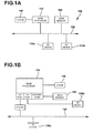
- FIGS 1A and 1B depict block diagrams of typical computer architectures useful in those embodiments as the remote machine 30, or the client machine 10.
- each computer 100 includes a central processing unit 102, and a main memory unit 104.
- Each computer 100 may also include other optional elements, such as one or more input/output devices 130a-130n (generally referred to using reference numeral 130), and a cache memory 140 in communication with the central processing unit 102.
- the central processing unit 102 is any logic circuitry that responds to and processes instructions fetched from the main memory unit 104.
- the central processing unit is provided by a microprocessor unit, such as those manufactured by Intel Corporation of Mountain View, California; those manufactured by Motorola Corporation of Schaumburg, Illinois; those manufactured by International Business Machines of White Plains, New York; or those manufactured by Advanced Micro Devices of Sunnyvale, California.
- Main memory unit 104 may be one or more memory chips capable of storing data and allowing any storage location to be directly accessed by the microprocessor 102, such as Static random access memory (SRAM), Burst SRAM or SynchBurst SRAM (BSRAM), Dynamic random access memory (DRAM), Fast Page Mode DRAM (FPM DRAM), Enhanced DRAM (EDRAM), Extended Data Output RAM (EDO RAM), Extended Data Output DRAM (EDO DRAM), Burst Extended Data Output DRAM (BEDO DRAM), Enhanced DRAM (EDRAM), synchronous DRAM (SDRAM), JEDEC SRAM, PC100 SDRAM, Double Data Rate SDRAM (DDR SDRAM), Enhanced SDRAM (ESDRAM), SyncLink DRAM (SLDRAM), Direct Rambus DRAM (DRDRAM), or Ferroelectric RAM (FRAM).
- SRAM Static random access memory
- BSRAM SynchBurst SRAM
- DRAM Dynamic random access memory
- FPM DRAM Fast Page Mode DRAM
- EDRAM Enhanced D
- FIG. 1A the processor 102 communicates with main memory 104 via a system bus 120 (described in more detail below).
- FIG. 1B depicts an embodiment of a computer system 100 in which the processor communicates directly with main memory 104 via a memory port.
- the main memory 104 may be DRDRAM.
- FIG. 1A and FIG. 1B depict embodiments in which the main processor 102 communicates directly with cache memory 140 via a secondary bus, sometimes referred to as a "backside" bus.
- the main processor 102 communicates with cache memory 140 using the system bus 120.
- Cache memory 140 typically has a faster response time than main memory 104 and is typically provided by SRAM, BSRAM, or EDRAM.
- the processor 102 communicates with various I/O devices 130 via a local system bus 120.
- Various buses may be used to connect the central processing unit 102 to the I/O devices 130, including a VESA VL bus, an ISA bus, an EISA bus, a MicroChannel Architecture (MCA) bus, a PCI bus, a PCI-X bus, a PCI-Express bus, or a NuBus.
- MCA MicroChannel Architecture
- PCI bus PCI bus
- PCI-X bus PCI-X bus
- PCI-Express PCI-Express bus
- NuBus NuBus.
- the processor 102 may use an Advanced Graphics Port (AGP) to communicate with the display.
- AGP Advanced Graphics Port
- FIG. 1B depicts an embodiment of a computer system 100 in which the main processor 102 communicates directly with I/O device 130b via HyperTransport, Rapid I/O, or InfiniBand.
- FIG. 1B also depicts an embodiment in which local busses and direct communication are mixed: the processor 102 communicates with I/O device 130a using a local interconnect bus while communicating with I/O device 130b directly.
- I/O devices 130 may be present in the computer system 100.
- Input devices include keyboards, mice, trackpads, trackballs, microphones, and drawing tablets.
- Output devices include video displays, speakers, inkjet printers, laser printers, and dye-sublimation printers.
- An I/O device may also provide mass storage for the computer system 100 such as a hard disk drive, a floppy disk drive for receiving floppy disks such as 3.5-inch, 5.25-inch disks or ZIP disks, a CD-ROM drive, a CD-R/RW drive, a DVD-ROM drive, DVD-RW drive, DVD+RW drive,, tape drives of various formats, and USB storage devices such as the USB Flash Drive line of devices manufactured by Twintech Industry, Inc. of Los Alamitos, California, and the iPod Shuffle line of devices manufactured by Apple Computer, Inc., of Cupertino, California.
- the client machine 10 may comprise or be connected to multiple display devices, which each may be of the same or different type and/or form.
- any of the I/O devices 130a-130n may comprise a display device or any type and/or form of suitable hardware, software, or combination of hardware and software to support, enable or provide for the connection and use of multiple display devices by the client machine 10.
- the client machine 10 may include any type and/or form of video adapter, video card, driver, and/or library to interface, communicate, connect or otherwise use the display devices.
- a video adapter may comprise multiple connectors to interface to multiple display devices.
- the client machine 10 may include multiple video adapters, with each video adapter connected to one or more of the display devices.
- any portion of the operating system of the client machine 10 may be configured for using multiple displays.
- one or more of the display devices may be provided by one or more other computing devices, such as remote machine 30 connected to the client machine 10, for example, via a network.
- These embodiments may include any type of software designed and constructed to use another computer's display device as a second display device for the client machine 10.
- a client machine 10 may be configured to have multiple display devices.
- an I/O device 130 may be a bridge between the system bus 120 and an external communication bus, such as a USB bus, an Apple Desktop Bus, an RS-232 serial connection, a SCSI bus, a FireWire bus, a FireWire 800 bus, an Ethernet bus, an AppleTalk bus, a Gigabit Ethernet bus, an Asynchronous Transfer Mode bus, a HIPPI bus, a Super HIPPI bus, a SerialPlus bus, a SCI/LAMP bus, a FibreChannel bus, or a Serial Attached small computer system interface bus.
- an external communication bus such as a USB bus, an Apple Desktop Bus, an RS-232 serial connection, a SCSI bus, a FireWire bus, a FireWire 800 bus, an Ethernet bus, an AppleTalk bus, a Gigabit Ethernet bus, an Asynchronous Transfer Mode bus, a HIPPI bus, a Super HIPPI bus, a SerialPlus bus, a SCI/LAMP bus, a FibreChannel bus, or a
- General-purpose computers of the sort depicted in FIG. 1A and FIG. 1B typically operate under the control of operating systems which control scheduling of tasks and access to system resources.
- the computers operate under control of hypervisors, which represent virtualized views of physical hardware as one or more virtual machines.
- Operating systems may execute in these virtual machines to control the virtual machine in a manner analogous to the way a native operating system controls a physical machine.
- Typical operating systems include: the MICROSOFT WINDOWS family of operating systems, manufactured by Microsoft Corp. of Redmond, Washington; the MacOS family of operating systems, manufactured by Apple Computer of Cupertino, California; OS/2, manufactured by International Business Machines of Armonk, New York; and Linux, a freely-available operating system distributed by Caldera Corp. of Salt Lake City, Utah, among others.
- the client machines 10 and 20 may be any personal computer (e.g., a Macintosh computer or a computer based on processors manufactured by Intel Corporation of Mountain View, California), Windows-based terminal, Network Computer, wireless device, information appliance, RISC Power PC, X-device, workstation, mini computer, main frame computer, personal digital assistant, television set-top box, living room media center, gaming console, mobile gaming device, NetPC's, thin client, or other computing device that has a windows-based desktop and sufficient persistent storage for executing a small, display presentation program.
- the display presentation program uses commands and data sent to it across communication channels to render a graphical display.
- Windows-oriented platforms supported by the client machines 10 and 20 can include, without limitation, WINDOWS 3.x, WINDOWS 95, WINDOWS 98, WINDOWS NT 3.51, WINDOWS NT 4.0, WINDOWS 2000, Windows 2003, WINDOWS CE, Windows XP, Windows Vista, MAC/OS, Java, Linux, and UNIX.
- the client machines 10 can include a visual display device (e.g., a computer monitor), a data entry device (e.g., a keyboard), persistent or volatile storage (e.g., computer memory) for storing downloaded application programs, a processor, and a mouse. Execution of a small, display presentation program allows the client machines 10 to participate in a distributed computer system model (i.e., a server-based computing model).
- the general-purpose computers of the sort depicted in FIG. 1A and FIG. 1B may have different processors, operating systems, and input devices consistent with the device and in accordance with embodiments further described herein.
- the computer system 100 can be any workstation, desktop computer, laptop or notebook computer, server, handheld computer, mobile telephone or other portable telecommunication device, media playing device, a gaming system, or any other type and/or form of computing, telecommunications or media device that is capable of communication and that has sufficient processor power and memory capacity to perform the operations described herein.
- the computer system 100 may comprise a device of the IPOD family of devices manufactured by Apple Computer of Cupertino, California, a PLAYSTATION 2 , PLAYSTATION 3, or PERSONAL PLAYSTATION PORTABLE (PSP) device manufactured by the Sony Corporation of Tokyo, Japan, a NINTENDO DS, NINTENDO GAMEBOY, NINTENDO GAMEBOY ADVANCED or NINTENDO REVOLUTION device manufactured by Nintendo Co., Ltd., of Kyoto, Japan, or an XBOX or XBOX 360TM device manufactured by the Microsoft Corporation of Redmond, Washington.
- PSP PERSONAL PLAYSTATION PORTABLE
- a client machine 10 is a mobile device
- the device may be a JAVA-enabled cellular telephone, such as those manufactured by Motorola Corp. of Schaumburg, Illinois, those manufactured by Kyocera of Kyoto, Japan, or those manufactured by Samsung Electronics Co., Ltd., of Seoul, Korea.
- the client machine 10 may be a personal digital assistant (PDA) operating under control of the PalmOS operating system, such as the devices manufactured by palmOne, Inc. of Milpitas, California.
- PDA personal digital assistant
- the client machine 10 may be a personal digital assistant (PDA) operating under control of the PocketPC operating system, such as the iPAQ devices manufactured by Hewlett-Packard Corporation of Palo Alto, California, the devices manufactured by ViewSonic of Walnut, California, or the devices manufactured by Toshiba America, Inc. of New York, New York.
- the client machine 10 is a combination PDA/telephone device such as the Treo devices manufactured by palmOne, Inc. of Milpitas, California.
- the client machine 10 is a cellular telephone that operates under control of the PocketPC operating system, such as those manufactured by Motorola Corp.
- a client machine 10 communicates with a remote machine 30 to determine an enumeration of resources available to the client machine 10 or to a user of the client machine 10.
- Resources may include, without limitation, computing environments, applications, documents, and hardware resources.
- the remote machine 30 provides the client machine 10 with address information associated with a remote machine 30' hosting a resource identified by the enumeration of resources.
- the client machine 10 communicates with the remote machine 30' to access the identified resource.
- the client machine 10 executes a resource neighborhood application to communicate with the remote machines 30 and 30'.
- each of the remote machines 30 provides the functionality required to identify and provide address information associated with a remote machine 30' hosting a requested resource.
- a block diagram depicts one embodiment of a system for providing access to a resource.
- a request to enumerate computing resources is transmitted from a client machine 10 (step 202).
- the request includes an identification of a user of the client machine 10.
- An enumeration of a plurality of resources available to the user of the requesting machine is provided by the remote machine (step 204).
- the client machine 10 transmits a request for access to a particular resource included in the enumeration (step 206).
- the transmitted request is a request for an enumeration of computing environments available to the client machine 10.
- the request is a request for an enumeration of computing environments supporting a particular application requested for execution by the client machine 10.
- the request is a request for access to a computing environment supported by a particular plurality of hardware resources.
- information associated with the client machine 10 or with a user of the client machine 10 is received with the request.
- credentials associated with the user, or with a user of the client machine 10 are received.
- the remote machine 30 receives a request for an enumeration of available computing environments from the client machine 10 with the information associated with the client machine 10, 10' or the user of the client machine 10.
- the remote machine 30 receives a transmission from a policy engine including the information.
- the remote machine 30 receives a transmission from a collection agent including the information.
- the remote machine 30 comprises a component receiving requests and associated information.
- a remote machine 30 functioning as a web server receives communications from the client machine 10, 10'. In one of these embodiments, the web server forwards the communications to a remote machine 30'. In one of these embodiments, the web server forwards the communications to a service on the remote machine 30'. In another of these embodiments where communications from the client machine 10, 10' are routed to a remote machine 30' by the web server, the remote machine 30 may be selected responsive to an Internet Protocol (lP) address of the client machine 10.
- LP Internet Protocol
- the user provides credentials to the remote machine 30 via a graphical user interface presented to the client machine 10, 10' by the remote machine 30.
- a remote machine 30"' having the functionality of a web server provides the graphical user interface to the client machine 10.
- a collection agent transmitted to the client machine 10, 10' by the remote machine 30 gathers the credentials from the client machine 10.
- collected data regarding available resources is accessed.
- collected data regarding computing environments is accessed.
- the accessed data includes an indication of a virtual machine providing access to one of the computing environments.
- the accessed data includes an indication of a location of the virtual machine.
- the accessed data concerning computing environments includes an indication of a plurality of hardware resources required to support the computing environments.
- the accessed data concerning computing environments includes an indication of a user or type of user authorized to access the computing environments.
- the accessed data is provided responsive to a request for identification of a computing environment providing access to an application program.
- the collected data is stored on a server, such as a remote machine 30.
- the server is in communication with a database storing the collected data.
- the server collects the data from a plurality of machines 30 in a machine farm 38.
- the data is received from at least one server responsive to a request for the information concerning the computing environments.
- the server collects the data from a hypervisor executing on a machine 30' in the machine farm 38.
- the server collects the data from a management component residing in a guest operating system provided by a virtual machine launched into a hypervisor executing on a machine 30' in the machine farm 38.
- the data is collected by an intermediate, brokering machine.
- the brokering machine maintains a database of a status of at least one computing environments and collects information from at least one machine providing access to at least one computing environments.
- the brokering machine collects information from a virtual machine service component residing in a virtual machine providing the computing environments.
- the brokering machine collects information from a virtual machine providing management functionality for a virtual machine providing a computing environment.
- the brokering machine collects information from a hypervisor on which an executing virtual machine provides a computing environment.
- the brokering machine comprises a machine 30 including a brokering module.
- data is gathered about the client system and a data set is generated from the gathered information.
- the accessed data is transmitted to the client system with an indication to the client system, made responsive to the generated data set, of each computing environment available to the client system.
- the accessed data is transmitted to the client system indicating to the client system, responsive to the application of a policy to the generated data set, each computing environment available to the client system.
- the indication includes at least one method of access available to the user seeking access to the computing environment.
- the indication includes at least one type of action associated with the computing environment which may be taken by, or on behalf of, the user of the client system.
- An enumeration of a plurality of resources available to the client machine 10 is provided (step 204).
- the enumeration is provided responsive to an application of a policy to received information associated with the user of the client machine 10 or the remote machine 30.
- the enumeration is provided responsive to a request from the user for a particular type of computing environment.
- the enumeration is provided responsive to a request from the user for computing environments providing access to a type of application program.
- the enumeration is provided responsive to a request from the user for computing environments supported by a specified plurality of hardware resources.
- an indication is transmitted to the client machine 10 of a plurality of computing environments available to a user of the client machine 10.
- the indication is generated responsive to accessing collected data associated with the plurality of computing environments.
- the accessed data is transmitted to the client machine 10 with an enumeration of computing environments available to the client machine 10.
- a determination is made, for each stored computing environment, as to whether that computing environment is available to the client machine 10.
- the collected information is transmitted to the client machine 10, the transmitted information displayable at the client machine 10 as icons in a graphical user interface window representing computing environments available to the client system.
- the collected information is transmitted to the client machine 10, the transmitted information displayable at the client machine 10 as icons in a graphical user interface window representing computing environments unavailable to the client machine 10.
- an enumeration of available computing environments is presented to a user of the client machine 10.
- an enumeration of applications is presented to a user of the client machine 10.
- a physical machine provides access to an enumerated application.
- a virtual machine provides access to an enumerated application.
- a virtual machine provides access to a computing environment from which a user of the client machine 10 may access the application.
- an enumeration of standard operating environments (such as a guest operating system pre-configured with a plurality of application programs) is provided to the user of the client machine 10.
- the enumeration of available resources includes an enumeration of a plurality of actions associated with a requested resource.
- the enumeration of the plurality of actions enables the user to request execution of a computing environment.
- the enumeration of the plurality of actions enables the user to request cloning of a computing environment.
- the enumeration of the plurality of actions enables the user to request shutdown of a computing environment.
- the enumeration of the plurality of actions enables the user to request that a computing environment be rebooted.
- the enumeration of the plurality of actions enables the user to request that a snapshot be taken of an existing state of a computing environment. In other embodiments, the enumeration of the plurality of actions enables the user to request that a previous snapshot of a computing environment be provided.
- a request is transmitted for access to a particular resource (step 206).
- a user of the client machine 10 requests a resource responsive to a received enumeration of available resources.
- the user requests a resource independent of a received enumeration.
- the user requests a resource by selecting a graphical representation of the resource presented on the client machine 10 by a client agent.
- the user requests a resource by selecting a graphical or textual representation of the resource presented to the user on a web server or other remote machine 30"'.
- the user requests an action associated with a resource. In one of these embodiments, the user requests execution of the resource. In another of these embodiments, the user requests termination of the resource. In still another of these embodiments, the user requests transmission of the resource, including transmission across an application streaming session. In yet another of these embodiments, the user requests that a resource be shutdown. In other embodiments, a request to execute an application is received from the client machine 10, the requested application requiring one of the computing environments. In still other embodiments, a request to access a file is received from the client machine 10, the requested file requiring execution within one of the computing environments.
- a remote machine 30 launches the Resource Neighborhood (RN) application and presents results of the RN application to the client machine 10.
- the remote machine 30 can launch the RN application 241 in response to a request 202 by the client machine 10 for an enumeration of available resources.
- the remote machine 30 provides an enumeration of available resources to the client machine 10 (step 204).
- the client machine 10 and remote machine 30' establish a connection (arrows 245 and 246). By this connection, the remote machine 30' can transfer the executable code of the particular application to the client machine 10, when the client machine 10 and remote machine 30' are operating according to the client-based computing model.
- the remote machine 30' can execute the particular application and transfer the graphical user interface to the client machine 10, when the client machine 10 and remote machine 30' are operating according to the server-based computing model.
- the remote machine 30' can execute the Resource Neighborhood application 241 and push the results back to the client machine 10 so that when the client machine 10 requests the Resource Neighborhood application, the Resource Neighborhood results are already available at the client machine 10.
- FIG. 2B shows another embodiment of a system in which the client machine 10 initiates execution of the Resource Neighborhood application 241 and a remote machine 30 presents the results of the RN application 241 to the client machine 10.
- the client machine 10 launches the Resource Neighborhood application (e.g., by clicking on a Resource Neighborhood icon representing the application 241).
- the client machine 10 directs a request 202 for the Resource Neighborhood application to the remote machine 30.
- the remote machine 30 can execute the Resource Neighborhood application 241, if the application is on the remote machine 30, and return the results to the client machine 10.
- the remote machine 30 can indicate (arrow 204) to the client machine 10 that the Resource Neighborhood application 241 is available on another remote machine, in this example remote machine 30'.
- the client machine 10 and remote machine 30' establish a connection (arrows 206 and 210) by which the client machine 10 requests execution of the Resource Neighborhood application 241.
- the remote machine 30' can execute the application 241 and transfer the results (i.e., the graphical user interface any audio output etc.) to the client machine 10.
- FIG. 2C shows another embodiment of a system in which a client machine 10 initiates execution of the Resource Neighborhood application 241, in this example via the World Wide Web.
- a client machine 10 executes a web browser application 280, such as NETSCAPE NAVIGATOR, manufactured by Netscape Communications, Inc. of Mountain View, Calif., INTERNET EXPLORER, manufactured by Microsoft Corporation of Redmond, Wash., or SAFARI, manufactured by Apple Computer of Cupertino, California.
- NETSCAPE NAVIGATOR manufactured by Netscape Communications, Inc. of Mountain View, Calif.
- INTERNET EXPLORER manufactured by Microsoft Corporation of Redmond, Wash.
- SAFARI manufactured by Apple Computer of Cupertino, California.
- the client machine 10 via the web browser 280, transmits a request 282 to access a Uniform Resource Locator (URL) address corresponding to an HTML page residing on remote machine 10.
- URL Uniform Resource Locator
- the first HTML page returned 284 to the client machine 10 by the remote machine 30 is an authentication page that seeks to identify the client machine 10 or the user of the client machine 10.
- the authentication page allows the client machine 10 to transmit user credentials, via the web browser 280, to the remote machine 30 for authentication. Transmitted user credentials are verified either by the remote machine 30 or by another remote machine 30 in the farm 38. This allows a security domain to be projected onto the remote machine 30. For example, if the remote machine 30 runs the WINDOWS NT operating system, manufactured by Microsoft Corporation of Redmond, Wash., and the authenticating machine runs the UNIX operating system, the UNIX security domain may be said to have been projected onto the remote machine 30.
- User credentials may be transmitted "in the clear," or they may be encrypted. For example, user credentials may be transmitted via a Secure Socket Layer (SSL) connection, which encrypts data using algorithms such as the RC4 algorithm, manufactured by RSA Security Inc. of Bedford, Massachusetts.
- SSL Secure Socket Layer
- an access control decision is made based on received information about the user resources available to the user of the client system are identified responsive to the access control decision.
- a policy is applied to the received information about the user.
- the remote machine 30 may verify the user credentials received from the client machine 10. Alternatively, the remote machine 30 may pass the user credentials to another remote machine for authentication. In this embodiment, the authenticating server may be in a different domain from the remote machine 30. Authenticated user credentials of the client machine 10 may be stored at the client machine 10 in a per-session cookie, in fields that are not displayed by the web browser 280, or in any other manner common in maintenance of web pages.
- a machine farm 38 with which the remote machine 30 is associated may allow guest users, i.e., users that do not have assigned user credentials, to access resources hosted by the farm 38.
- the authentication page may provide a mechanism for allowing a client machine 10 to identify that it is a guest user, such as a button or menu selection.
- the remote machine 30 may omit the authentication page entirely.
- the remote machine prepares and transmits to the client machine 10 an HTML page 288 that includes a Resource Neighborhood window 258 in which appears graphical icons 257, 257' representing resources to which the client machine 10 has access.
- a user of client machine 10 requests access to a resource represented by icon 257 by clicking that icon 257.
- FIG. 3A shows one embodiment of a process of communication among the client machine 10 and multiple remote machines 30, 30'.
- the client machine 10 has an active connection 372 with the remote machine 30'.
- the client machine 10 and remote machine 30' can use the active connection 372 to exchange information regarding the status or execution of a first resource.
- User credentials may be stored at the client machine 10. Such storage of the user credentials can be in cache memory or persistent storage.
- the Resource Neighborhood application (not shown on FIG. 3A ) runs on the client machine 10.
- the client machine display has a Resource Neighborhood window 258 in which appears a graphical icon 257 representing a second resource.
- a user of the client machine 10 can access the second resource by double-clicking the icon 257 with the mouse.
- the request passes to the remote machine 30 via connection 359.
- the remote machine 30 indicates to the client machine 10 via connection 359 that the sought-after resource is available on remote machine 30'.
- the client machine 10 signals the remote machine 30' to establish a second connection 370.
- the remote machine 30' requests the user credentials from the client machine 10 to authenticate access to the second resource.
- the client machine 10 and remote machine 30' Upon a successful authentication, the client machine 10 and remote machine 30' establish the second connection 370 and exchange information regarding status of or execution of the second resource.
- the remote machine does not request user credentials to establish the second connection 370.
- the remote machine 30' may use the credentials supplied by the user of client machine 10 to establish the connection 372 to also establish the second connection 370. Accordingly, the client machine 10 and the remote machine 30' communicate with each other over multiple connections.
- FIG. 3B shows one embodiment of a system of communication among the client machine 10, master remote machine 30, and servers 32, 34, and 36.
- the client machine 10 has an active connection 373 with the remote machine 32.
- the client machine 10 and remote machine 32 can use the active connection 373 to exchange information regarding the status of or execution of a first resource.
- User credentials may be stored at the remote machine 32 in cache memory or in persistent storage.
- the Resource Neighborhood application runs on the remote machine 32.
- the remote machine 32 includes software providing a server-based client engine 62, enabling the remote machine 32 to operate in the capacity of the client machine 10.
- the client machine 10 display has a Resource Neighborhood window 258 in which appear graphical icons 357, 357' representing a second resource and a third resource, respectively. A user of the client machine 10 can access the second resource by double-clicking the icon 357.
- the request to launch the second resource passes to the remote machine 32 via active connection 373, and the remote machine 32 forwards the request to the master remote machine 30 (arrow 365).
- the master remote machine 30 indicates (arrow 365) to the remote machine 32 that the sought-after resource is available on server 34.
- the remote machine 32 contacts the server 34 to establish a connection 366.
- the server 34 obtains the user credentials of the client machine 10 from the remote machine 32.
- the remote machine 32 and server 34 establish the connection (arrow 366) by which the remote machine 32 requests access to the second resource and the server 34 returns the results to the remote machine 32.
- the remote machine 32 forwards the results to the client machine 10, where the results are displayed. Accordingly, the information exchanged between the client machine 10 and the server 34 "passes through" the remote machine 32.
- the client machine 10 can launch the third resource by double-clicking the icon 357'.
- the request to launch the third resource passes to the remote machine 32.
- the remote machine 32 forwards the request to the master remote machine 30.
- the master remote machine 30 indicates that the server 36 can be used to access the third resource.
- the remote machine 32 and the server 36 establish a connection (arrow 374) by which the remote machine 32 requests access to the third resource, and the server 36 returns the results to the remote machine 32.
- the server 36 can authenticate the user credentials of the user of the client machine 10, which are obtained from the remote machine 32.
- the remote machine 32 forwards the results to the client machine 10 where the results are displayed. Accordingly, the results of accessing the third resource pass between the client machine 10 and the server 36 through the remote machine 32.
- FIG. 3C shows another embodiment of a system of communication among the client machine 10, a master remote machine 30, and servers 32 and 34.
- the client machine 10 has an active connection 376 with server 32.
- the client machine 10 and server 32 can use the active connection 376 to exchange information regarding the access to a first resource.
- the client machine 10 can store user credentials in cache memory or in persistent storage.
- the Resource Neighborhood application runs on the server 32.
- the client machine 10 display has a Resource Neighborhood window 258 in which appears a graphical icon 257 representing a second resource.
- a user of the client machine 10 can access the second resource by double-clicking the icon 257.
- the request to access the second resource passes to the server 32.
- the server 32 responds (i.e., "calls back") to the client machine 10 by returning resource-related information such as the name of the resource and capabilities needed by the client machine 10 to access the second application.
- the client machine 10 With the information provided by the server 32, the client machine 10 then communicates with the master remote machine 30 via connection 377 to determine the server for accessing the second resource.
- that server is server 34.
- the client machine 10 then establishes a connection 378 to the server 34.
- Server 34 requests the user credentials from the client machine 10 to authenticate the user of the client machine 10.
- the client machine 10 accesses the second resource on the server 34, and the server 34 returns the results to the client machine 10 via the established connection 378. Accordingly, the client machine 10 can have multiple active connections between the multiple servers.
- FIG. 3D shows one embodiment of a system of communication between the client machine 10, a remote machine 30 that in this example acts as a web server, and a second remote machine 30'.
- the client machine 10 authenticates itself to the remote machine 30 as described above in connection with FIG. 2C .
- the remote machine 30 accesses an output display template 390, such as an SGML, HTML or XML file, to use as a base for constructing the Resource Neighborhood window to transmit to the client machine 10.
- the Resource Neighborhood window may display an enumeration of resources available to the client.
- the enumeration of resources may include an enumeration of available application programs or computing environments.
- the template may be stored in volatile or persistent memory associated with the server 30 or it may be stored in mass memory 392, such as a disk drive or optical device, as shown in FIG. 3D .
- the template 390 is a standard SGML, HTML, or XML document containing Resource Neighborhood-specific tags that are replaced with dynamic information.
- the tags indicate to the server 30 where in the output display to insert information corresponding to available resources, such as icon images.
- the Resource Neighborhood-specific tags are embedded within comments inside a file, allowing the file to remain compatible with standard interpreters.
- the Resource Neighborhood-specific tags are extensions of the markup language used as the base for the template.
- ControlField field value This tag is used to set the value of data that either persists between Resource Neighborhood web pages, is set by the user, or is used to help in cross page navigation, such as user name, domain, password, template, and resource.
- DrawResourceNeighborhood This tag is used to draw a Resource Neighborhood display at this location in an output display.
- ResourceName This tag is replaced by the name of the published resource in the current context.
- WindowType This tag is replaced by the window type of the published resource in the current context.
- WindowHeight This tag is replaced by the window height of the published resource in the current context.
- WindowWidth This tag is replaced by the window width of the published resource in the current context.
- WindowScale This tag is replaced by the window scale of the published resource in the current context.
- WindowColors This tag is replaced by the color depth of the published resource in the current context.
- SoundType This tag is replaced by the sound setting of the published resource in the current context.
- VideoType This tag is replaced by the video setting of the published resource in the current context.
- EncryptionLevel This tag is replaced by the encryption level of the published resource in the current context.
- Icon This tag is replaced by the icon of the published resource in the current context.
- the template is constructed dynamically using, for example, COLD FUSION, manufactured by Allaire Corp. of Cambridge, Mass. or ACTIVE SERVER PAGES manufactured by Microsoft Corporation of Redmond, Wash.
- the template may be static.
- the Resource Neighborhood application parses the template, replacing Resource Neighborhood-specific tags as noted above. Tags that are not Resource Neighborhood-specific are left in the file to be parsed by the browser program 80 executing on the client 10.
- a template parser object accepts an HTML template as input, interprets Resource Neighborhood-specific tags present in the template, and outputs the original template with all Resource Neighborhood tags replaced with appropriate text.
- the template parser object can be passed a cookie, a URL query string, or a control field from a web server interface to provide the information with which Resource Neighborhood-specific tags should be replaced.
- a web server receives a request from the client machine 10 for an enumeration of available computing environments.
- the web server executes an application to access data regarding the computing environments.
- a page template is retrieved from a database.
- a page is created, at the web server, describing a display of stored computing environment images available to the client machine 10 responsive to the collected information and the retrieved page template, and the created page is transmitted to the client machine 10, indicating to the client machine 10 each computing environment available to the client machine 10.
- computing environment images may comprise virtual machine images, resource images, screenshots of suspended virtual machines, and other images selected by a user or administrator for presentation to the user.
- an output display is created indicating each computing environment available to the client machine 10 and transmitting the created output display to the client machine 10.
- an output display comprising a page constructed in a markup language, the output display indicating each computing environment available to the client system and transmitted to the client system.
- the Resource Neighborhood application allows scripts to access information via an application programming interface. Scripts may be written in, for example, VBScript or Jscript.
- the scripting language is used to dynamically generate an output display using information returned by the application in response to queries posed by the script. Once the output display is generated, it is transmitted to client machine 10 for display by the browser program 80.
- a user of the client machine 10 can access a resource by clicking an icon 257, 257' displayed in the Resource Neighborhood web page.
- each icon 257, 257' is associated with an encoded URL that specifies: the location of the resource (i.e., on which remote machines it is hosted or, alternatively, the address of a master remote machine, a gateway, or other remote machine 30); a launch command associated with the resource; and a template identifying how the results of accessing the resource should be displayed (i.e., in a window "embedded" in the browser or in a separate window).
- the URL includes a file, or a reference to a file, that contains the information necessary for the client to create a connection to the remote machine hosting the resource.
- the client machine 10 establishes a connection (arrow 394) with the remote machine 30' identified as hosting the requested resource and exchanges information regarding access to the desired resource.
- the connection 394 is made using the Independent Computing Architecture (ICA) protocol, manufactured by Citrix Systems, Inc. of Fort Lauderdale, Fla.
- ICA Independent Computing Architecture
- the connection is made using: the RDP protocol, manufactured by Microsoft Corp. of Redmond, Washington; the X11 protocol; or the Virtual Network Computing (VNC) protocol, manufactured by AT&T Bell Labs.
- the client machine 10 may display the results of accessing the resource in a window separate from the web browser 280, or it may "embed" application output within the web browser.
- FIG. 3E depicts an embodiment in which a remote machine 30 acts as an intermediary for a machine farm 38 and comprises a broker module 310, a transmitter 312, a receiver 314, and a transceiver 316.
- the broker module 310 accesses collected data regarding resources, including application programs, computing environments, and hardware resources. In some embodiments, the broker module 310 accesses collected data regarding resources and determines for each resource whether that resource image is available to a client machine 10. In some embodiments, the server further comprises a database storing the collected data. In one of these embodiments, the broker module 310 determines for each resource whether that resource image is available to a client machine 10 based on the collected data. In other embodiments, the broker module 310 receives user credentials and determines for each resource whether that resource image is available to a client machine 10 based on the user credentials and the collected data.
- the server further comprises an output display creation engine creating output displays indicating each resource available to the client machine 10.
- the output display creation engine creates a page describing a display of the resources available to a client system, the page created responsive to the collected information and a page template.
- the transmitter 312 transmits accessed data to the client machine 10 indicating to the client machine 10 each resource determined to be available to the client machine 10.
- the transmitted data is displayable at the client system as icons in a graphical user interface window representing resources available to the client system.
- the transmitted data is displayable at the client system as icons in a graphical user interface window representing resources unavailable to the client system.
- the receiver 314 receives a request to access one of the available resources.
- the receiver receives user credentials from the client machine 10.
- the receiver receives a request to access an application program available through one of the available resources, such as an available computing environment.
- a database storing the collected information and the service module determines for each resource stored by the plurality of servers whether that resource image is available to a client machine 10 based on the user credentials and the collected information. In yet other embodiments, a determination is made as to an availability of resources, such as virtual machines or application servers, providing access to the available resources.
- the transceiver 316 provides a connection between the client machine 10 and a virtual machine providing the requested resource. In some embodiments, the transceiver 316 provides a connection between the client machine 10 and a virtual machine providing the requested resource and the transceiver 316 establishes a presentation-layer protocol connection. In one of these embodiments, the transceiver 316 establishes an X11 or VNC connection. In another of these embodiments, the transceiver 316 establishes an ICA connection. In still another of these embodiments, the transceiver 316 establishes an RDP connection.
- An intermediary machine of the sort just described may be used as any one of the remote machine 30 described above in FIGs. 1-1B , 2A-2B , and 3A-3D .
- FIG. 4 illustrates one embodiment of program components for a client-based implementation of the Resource Neighborhood application.
- a client-based implementation of the Resource Neighborhood application 416 can be used in a network using either the server-based computing model in which the servers execute the Resource Neighborhood application or in a client-based computing model in which the client machine 10 executes the Resource Neighborhood application locally.
- the Resource Neighborhood application includes a Resource Neighborhood Service (RNSVC) component 444, a resource database component 448, a Resource Neighborhood Application Program Interface (RNAPI) component 452, a Resource Neighborhood User Interface component 456, and a local cache 460.
- RNSVC Resource Neighborhood Service
- RNAPI Resource Neighborhood Application Program Interface
- the remote machine 30, includes the service component (RNSVC) 444 and the resource authorization cache 448.
- the client machine 10 which is a representative example of a client machine 10 that can support a client-based implementation of the Resource Neighborhood application, includes the application program interface RNAPI 452, the user interface user interface component 456, and the local cache 460 components.
- the RNAPI 452 communicates with the user interface component 456 and the local cache 460.
- the RNSVC 444 communicates with the resource authorization cache 448 and with the RNAPI 452 on the client machine 10 via communications link 462.
- the communications link 462 can be established by, for example, using the ICA protocol, the RDP protocol, the X11 protocol, the VNC protocol, or any other suitable presentation-level protocol designed to run over industry standard transport protocols, such as TCP/IP, IPX/SPX, NetBEUI, I , using industry-standard network protocols, such as ISDN, frame relay, and asynchronous transfer mode (ATM) and which provides for virtual channels, which are session-oriented transmission connections that can be used by application-layer code to issue commands for exchanging data.
- the communications link 462 may also be established by protocols that support RPC or RPC-equivalents such as SOAP and HTTP.
- the communications link 462 may also be a communications link 150 as described above.
- the virtual channel commands are designed to be closely integrated with the functions of client machines.
- the ICA protocol can support the Resource Neighborhood virtual channel.
- the Resource Neighborhood virtual channel protocol can include four groups of commands:
- the resource authorization cache 448 may be a cache of the authorized user and group information for all the public (i.e., published) resources in a machine farm 38 or in a group of trusted domains. Each remote machine in a machine farm 38 can maintain its own resource-related information in persistent storage and build up the resource authorization cache 448 in volatile storage. In another embodiment, all collected resource-related information in the resource authorization cache 448 can be stored in persistent storage and made accessible to each other server in the machine farm 38.
- the resource authorization cache 448 can be implemented in a proprietary format (e.g., as a linked list in memory) or using Novell's Directory Services (NDS) or any directory service adhering to the X.500 standard defined by the International Telecommunication Union (ITU) for distributed electronic directories.
- the resource authorization cache 448 may be implemented as a standard relational database.
- the resource authorization cache 448 includes a list of remote machines. Each remote machine in the list has an associated set of resources. Associated with each resource is resource-related information that can include the resource name, a list of remote machines, and client users that are authorized to use that resource.
- resource-related information can include the resource name, a list of remote machines, and client users that are authorized to use that resource.
- An overly-simplified example of the resource-related information maintained in the database is illustrated by the following Table 2.
- Users A and B are users of the client machines 10, "n/a" indicates that a desired application program is hosted, but is not available to client machine users, and "-" indicates that the application program is not hosted. TABLE 2 Remote Machine Name SpreadSheet Customer Database Word Processor Calculator Server 30 User A User B n/a - Server 32 User B n/a User A - Server 34 - - - User A User B
- Table 2 shows: a list of servers 30, 32, 34; applications hosted by the servers (Spreadsheet, Customer Database, Word Processor, and Calculator); and those users who are authorized to use the applications.
- the server 30 hosts the Spreadsheet program, the Customer Database and the Word Processor.
- User A is authorized to use the Spreadsheet
- User B is authorized to use the Customer Database
- no users are authorized to use the Word Processor. It is to be understood that other techniques can be used to indicate who is authorized to use a particular application.
- the user information stored in the database can be used to indicate those users who are unauthorized to use a particular application rather than those who are authorized, or to indicate that multiple users may access a resource on a remote machine 30, or to indicate that a predetermined group of users are authorized to access a particular resource.
- Table 2 depicts an embodiment in which the resources that are available are application programs, a similar technique may be used for computing environments and other resources.
- the remote machine 30 obtains the resource-related information from each other machine in the machine farm 38 regarding the resources on those remote machines, including control information that indicates which client users and remote machines are permitted to access each particular resource.
- the resource-related information maintained in the database may or may not persist across re-boots of the remote machine 30.
- Each remote machine 30 having the Resource Neighborhood application installed thereon executes the RNSVC software 444.
- the RNSVC software 444 operating on each remote machine 30 establishes a communication link (e.g. a named pipe) with at least one other and, in some embodiments, each other remote machine 30.
- the remote machines 30 exchange resource-related information on the communications links.
- the RNSVC software 444 collects the resource-related information from the other remote machine 30 in the machine farm 38 through remote registry calls (e.g., the service component 444 transmits a datagram to other remote machine 30 in the farm 38 requesting the resource-related information corresponding to the resources hosted by those remote machine 30).
- the resource authorization cache is populated by system administrators of by programs and scripts communicating with remotes machines 30.
- the RNSVC 444 software also maintains the relationships of groups and users to published resources in the resource authorization cache 448 and accesses the information when authenticating a client user. An administrator of the remote machine 30 can use a user interface to configure the RNSVC 444.
- RNSVC software 444 includes implementing the services and functions requested by the RNAPI 452 and communicating with the RNAPI 452 on the client machine 10 using a Resource Neighborhood virtual channel driver (VCRN).
- VCRN operates according to the Resource Neighborhood virtual channel protocol described.
- the RNAPI 452 is a set of software functions or services that are used by the Resource Neighborhood application to perform various operations (e.g., open windows on a display screen, open files, and display message boxes).
- the RNAPI 452 provides a generic mechanism for accessing user interface elements (e.g., icons) produced by running the Resource Neighborhood application and objects in a legacy (i.e., predecessor or existing for some time) client user interface.
- the accessing mechanism can launch the resource on the remote machine 30, if necessary (e.g., when the client machine 10 is unable to locally execute the application).
- the RNAPI 452 provides all published resource information to the user interface component 456 for display on the screen 12 ( FIG. 1 ) of the client machine 10.
- the RNAPI 452 also manages machine farm 38 logons in a local database of logon credentials (e.g., passwords) for users of the client machine 10 to support the single authentication feature. Credentials may or may not be persistent across a reboot (power-off and on cycles) of the client machine 10.
- logon credentials e.g., passwords
- the RNAPI 452 provides automatic and manual management for Resource Neighborhood objects stored in the local cache 460.
- the local cache 460 can either be refreshed manually by the user of the client machine 10, or at a user-definable refresh rate, or by the server at any time during a connection.
- the RNAPI 452 can build remote application file resource associations and manage the "Start" menu and desktop icons for resource object shortcuts.
- the user interface module 456 interfaces the RNAPI 452 and can be a functional superset of an existing client user interface (e.g., Remote Resource Manager).
- the user interface module 456 accesses the information stored in the local cache 460 through the RNAPI 452 and visually presents that information to the user on the display screen 12 ( FIG. 1 ) of the client machine 10.
- the displayed information is a mixture of information generated by a user of the client machine 10 and information obtained by the Resource Neighborhood application.
- the user interface module 456 can also show the user all resources that the user is currently accessing and all active and disconnected sessions.
- the user interface module 456 can present a variety of graphical components, such as windows and pull-down menus, to be displayed on the display screen 12 ( FIG. 1 ).
- a display of a combination of such graphical user interface components is generally referred to as a "desktop.”
- a desktop produced by the user interface module 456 can include a Resource Neighborhood window displaying the neighborhood of resources available to the user of the client machine 10. These resources may be a filtered combination of the published resources hosted by a machine farm 38.
- the user interface module 456 can generate a Resource Neighborhood window for each machine farm 38 or merge the resources from different machine farms 38 under a single Resource Neighborhood window.
- the Resource Neighborhood window includes a folder for each machine farm 38. Clicking on one of the folders produces a window containing a representation (e.g., an icon) of each hosted resource available to the user, e.g., see FIGS. 6A and 6B .
- the Resource Neighborhood window becomes the focal point for accessing published resources, and the user interface module 456 can be used to access resources and launch applications through the RNAPI 452.
- the user of the client machine 10 can use the mouse 18 ( FIG. 1 ) to select one of the displayed icons and launch the associated resource.
- a feature of a client-based implementation is that the user can browse the objects displayed in the Resource Neighborhood window although the client machine is offline, that is, the connection 462 is inactive. Also, a user of the client machine 10 can drag application objects and folders out of the Resource Neighborhood window and into other graphical components (e.g., other windows, folders, etc.) of the desktop.
- FIG. 5 shows one embodiment of the program components for a server-based implementation of the Resource Neighborhood application.
- the components include a Service (RNSVC) component 544', a Resource Database component 548', an Application Program Interface (RNAPI) component 552', a User Interface component 556' and a local cache 560'.
- RNSVC Service
- RNAPI Application Program Interface
- Each software component 544', 548', 552', 556', and 560' is installed on the application server 30'.
- the software components for the server-based implementation correspond to the software components for the client-based implementation of FIG. 4 .
- the functionality of each server-based software component is similar to the client-based counterpart, with differences or added capabilities described below.
- the RNSVC 544' communicates with the resource database 548' and with the RNAPI 552' using local procedure calls.
- the RNAPI 552' also communicates with the user interface module 556' and the local cache 560'.
- the client machine 10 logs on to the network 40 ( FIG. 1 ), the server 30' develops and maintains a database containing the resource related information collected from the other machines in the machine farm 38, and a communication link is established between the server 30' and the client machine 20.
- the application server 30' may be in communication with the client machine 10 via an ICA connection 562'.
- the user of the client machine 10 connects to an initial desktop (at the server 30') and launches the Resource Neighborhood application from within that desktop environment.
- the connection to the initial desktop can occur automatically, e.g., via a logon script of the client machine 20, via an entry in a Startup group, or by another centrally managed server specific mechanism. All remote application management and launching is accomplished through this initial desktop.
- the server 30' uses the user credentials to determine those resources that the user of the client machine 10 is authorized to use.
- a Resource Neighborhood graphical window is returned to the client machine 10 and displayed on the client screen 22 ( FIG. 1 ). This window can contain icons representing the available and, possibly, the unavailable resources that are in the Resource Neighborhood of the client machine 20.
- the web-based Resource Neighborhood application includes a group of objects that manage various aspects of a resource.
- the Resource Neighborhood application includes three primary object classes that "plug in" to a web server: a gateway object cass; a credentials object class; and a resources object class.
- the object classes are provided as JavaBeans. The three primary object classes facilitate: validation of user credentials into a server farm; generation of lists of published resources that a specified user may access; provisioning of detailed information about a specific published resource; and conversion of resource application information into a format compatible with the protocol over which connection will be made.
- the objects can be accessed in a number of different ways. For example, they may be compiled as COM objects and made available to the web server as ActiveX components.
- the JavaBeans can be used in their native form, such as when the server uses Java Server Pages technology.
- the JavaBeans can be instantiated and used directly in a Java Servlet.
- the remote machine 30 can instantiate the JavaBeans as COM objects directly.
- a credentials object class manages information necessary to authenticate a user into a target machine farm 38.
- a credentials object passes stored user credentials to other Resource Neighborhood objects.
- the credentials object is an abstract class that cannot be instantiated and represents a user's credentials.
- class extensions may be provided to allow different authentication mechanisms to be used, including biometrics, smart cards, token-based authentication mechanisms such as challenge-response and time-based password generation, or others.
- a "clear text credentials" extension may be provided that stores a user's name, domain, and password in plain text.
- a gateway object class handles communications with a target machine farm 38.
- the gateway object class is provided as an abstract Java class that cannot be instantiated.
- a particular gateway object may retrieve resource information by communicating with a machine farm 38 using a particular protocol, reading cached resource information, a combination of these two methods, or other various methods.
- the gateway object class may cache information to minimize communication with a target machine farm 38. Extensions to the gateway object may be provided to communicate with the machine farm 38 over specific protocols, such as HTTP. In one embodiment, an extension class is provided that allows the gateway object to communicate with the machine farm 38 via WINDOWS NT named pipes. The gateway object may provide an application programming interface hook that allows other Resource Neighborhood objects to query the object for application information.
- a resources object class contains information about published resources and returns information about resources hosted by the machine farm 38 in order to create the Resource Neighborhood web page.
- the resources object class creates objects representing resources by retrieving information relating to the resources, either from an object created by the gateway object or directly from the machines in the machine farm 38.
- a resources object acts as a container for certain properties of the resource, some settable and some not settable, such as: the name of the resource (not settable); the width of the client window, in pixels, for this resource (settable); the height of the client window, in pixels, for this resource (settable); the number of colors to use when connecting to the resource (settable); the severity of audio bandwidth restriction (settable); the level of encryption to use when connecting to the resource (settable); the level of video to use when connecting to this resource (settable); whether the resource should be placed on a client's start menu (settable); whether the resource should be placed on the client's desktop (settable); the identity of the Resource Neighborhood folder to which the resource belongs (settable); the description of the resource (settable); the source of the graphics icon file for the resource (settable); the type of window that should be used when connecting to the resource (not settable); and whether to override default parameters for the object.
- FIG. 6A is a screenshot of one embodiment of Resource Neighborhood window 620 that can be displayed on the screen 12, 22 ( FIG. 1 ) of a client machine 10, 10' after the Resource Neighborhood application has executed.
- the window 120 includes graphical icons 622.
- Each icon 622 represents a resource that is hosted by one of the machines in a machine farm 38.
- Each represented resource is available to the user of the client machine 10. The user can select one of the resources using the mouse 18, 28 or keyboard 14, 24.
- FIG. 6B is a screenshot of another embodiment of a Resource Neighborhood window 624 that can be displayed on the screen 12, 22 ( FIG. 1 ) of a client machine 10, 10' after the Resource Neighborhood application has executed.
- the window 624 includes graphical icons 626, 628.
- Each icon 626, 628 represents a resource that is hosted by one of the machines in a machine farm 38.
- Each resource represented by one of the icons 626 is available to the user of the client machine 10. The user can select one of the resources using the mouse 18, 28 or keyboard 14, 24.
- the screenshots of FIGS. 6A and 6B are similar, except that icons 622, 626, 628 are displayed within a browser window.
- Each resource represented by one of the icons 628 is unavailable to the user of the client machine 10, although such resources are present in the server farm.
- the unavailability of these resources can be noted on the display screen (e.g., "X"s can be drawn through the icons 628).
- An attempt to access such a resource can trigger a message indicating that the user is not authorized to access the resource.
- the attempt may invoke a method allowing the user of the client machine 10 to request access to the resource.
- the resource comprises a computing environment.
- a connection is established between the client machine 10 and a virtual machine hosting the requested computing environment.
- a presentation layer protocol is used in establishing the connection between the client system and the virtual machine.
- the X11 protocol is used in establishing the connection.
- the Remote Desktop Protocol RDP
- the Independent Computing Architecture (ICA) protocol is used in establishing the connection.
- a connection is established between the client machine 10 and a physical machine, such as a traditional workstation or server, hosting the requested computing environment. In other embodiments, a connection is established between the client machine 10 and a hardware partition hosting the requested computing environment.
- an enumeration of a plurality of resources available to the client machine 10 is provided (step 204) responsive to a determination by a policy engine regarding whether and how a client machine may access a resource.
- the policy engine may collect information about the client machine prior to making the determination.
- FIG. 7A one embodiment of a computer network is depicted which includes a client machine 10, a machine farm 38, a collection agent 704, a policy engine 706, a policy database 708, and a resource server 30'.
- the policy engine 706 is a remote machine 30. Although only one client machine 10, collection agent 704, policy engine 706, machine farm 38, and resource server 30' are depicted in the embodiment shown in Figure 7A , it should be understood that the system may provide multiple ones of any or each of those components.
- the collection agent 704 communicates with the client machine 10, retrieving information about the client machine 10, and transmits the client machine information 712 to the policy engine 706.
- the policy engine 706 makes an access control decision by applying a policy from the policy database 708 to the received information 712.
- the client machine 710 transmits to the policy engine 706 a request 206 for resource enumeration.
- the policy engine 706 resides on a resource server 30'.
- the policy engine 706 resides on a remote machine 30.
- a resource server 30' receives the request 206 from the client machine 10 and transmits the request 206 to the policy engine 706.
- the client machine 10 transmits a request 206 for resource enumeration to an intermediate remote machine 30"' (not shown), which transmits the request 206 to the policy engine 706.
- the client machine 10 transmits the request 206 over a network connection such as those described above.
- the policy engine 706 initiates information gathering by the collection agent 704.
- the collection agent 704 gathers information regarding the client machine 10 and transmits the information 712 to the policy engine 706.
- the collection agent 704 gathers and transmits the information 712 over a network connection.
- the collection agent 704 comprises bytecode, such as an application written in the bytecode programming language JAVA.
- the collection agent 704 comprises at least one script.
- the collection agent 704 gathers information by running at least one script on the client machine 10.
- the collection agent comprises an Active X control on the client machine 10.
- An Active X control is a specialized Component Object Model (COM) object that implements a set of interfaces that enable it to look and act like a control.
- COM Component Object Model
- the policy engine 706 transmits the collection agent 704 to the client machine 10. In some embodiments, the policy engine 706 requires another execution of the collection agent 704 after the collection agent 704 has transmitted information 712 to the policy engine 706. In some of these embodiments, the policy engine 706 requires another execution of the collection agent 704 because the policy engine 706 may have insufficient information 712 to determine whether the client machine 10 satisfies a particular condition. In other embodiments, the policy engine 706 requires a plurality of executions of the collection agent 704 in response to received information 712.
- the policy engine 706 transmits instructions to the collection agent 704 determining the type of information the collection agent 704 gathers from the client machine 10.
- a system administrator may configure the instructions transmitted to the collection agent 704 from the policy engine 706. This provides greater control over the type of information collected. This also expands the types of access control decisions that the policy engine 706 can make, due to the greater control over the type of information collected.
- the collection agent 704 gathers information 712 including, without limitation, machine ID of the client machine 10, operating system type, existence of a patch to an operating system, MAC addresses of installed network cards, a digital watermark on the client device, membership in an Active Directory, existence of a virus scanner, existence of a personal firewall, an HTTP header, browser type, device type, network connection information such as internet protocol address or range of addresses, machine ID of the remote machine 30, date or time of access request including adjustments for varying time zones, and authorization credentials.
- information 712 including, without limitation, machine ID of the client machine 10, operating system type, existence of a patch to an operating system, MAC addresses of installed network cards, a digital watermark on the client device, membership in an Active Directory, existence of a virus scanner, existence of a personal firewall, an HTTP header, browser type, device type, network connection information such as internet protocol address or range of addresses, machine ID of the remote machine 30, date or time of access request including adjustments for varying time zones, and authorization credentials.
- the device type is a personal digital assistant. In other embodiments, the device type is a cellular telephone. In other embodiments, the device type is a laptop computer. In other embodiments, the device type is a desktop computer. In other embodiments, the device type is an Internet kiosk. In still other embodiments, the device type is a game console.
- the digital watermark includes data embedding.
- the watermark comprises a pattern of data inserted into a file to provide source information about the file.
- the watermark comprises hashed data files to provide tamper detection.
- the watermark provides copyright information about the file.
- the network connection information pertains to bandwidth capabilities. In other embodiments, the network connection information pertains to the Internet Protocol address of the client machine 10. In still other embodiments, the network connection information consists of the Internet Protocol address of the client machine 10. In one embodiment, the network connection information comprises a network zone identifying the logon agent to which the client machine 10 provided authentication credentials.
- the authorization credentials include a number of types of authentication information, including without limitation, user names, client names, client addresses, passwords, Personal Identification Numbers (PINs), voice samples, one-time passcodes, biometric data, digital certificates, tickets, etc. and combinations thereof.
- the policy engine 706 After receiving the gathered information 712, the policy engine 706 makes an access control decision based on the received information 712.
- a block diagram depicts one embodiment of a policy engine 706, including a first component 720, including a condition database 722 and a logon agent 724, and a second component 730, including a policy database 732.
- the first component 720 applies a condition from the condition database 722 to information 712 received about client machine 10 and determines whether the received information 712 satisfies the condition.
- a condition may require that the client machine 10 execute a particular operating system to satisfy the condition. In other embodiments, a condition may require that the client machine 10 execute a particular operating system patch to satisfy the condition. In still other embodiments, a condition may require that the client machine 10 provide a MAC address for each installed network card to satisfy the condition. In some embodiments, a condition may require that the client machine 10 indicate membership in a particular Active Directory to satisfy the condition. In another embodiment, a condition may require that the client machine 10 execute a virus scanner to satisfy the condition. In other embodiments, a condition may require that the client machine 10 execute a personal firewall to satisfy the condition. In some embodiments, a condition may require that the client machine 10 comprise a particular device type to satisfy the condition. In other embodiments, a condition may require that the client machine 10 establish a particular type of network connection to satisfy the condition.
- the first component 720 stores an identifier for that condition in a data set 726.
- the received information satisfies a condition if the information makes the condition true.
- a condition may require that a particular operating system be installed. If the client machine 10 has that operating system, the condition is true and satisfied.
- the received information satisfies a condition if the information makes the condition false.
- a condition may address whether spyware exists on the client machine 10. If the client machine 10 does not contain spyware, the condition is false and satisfied.
- the logon agent 724 resides outside of the policy engine 706. In n other embodiments, the logon agent 724 resides on the policy engine 706.
- the first component 720 includes a logon agent 724, which initiates the information gathering about client machine 10.
- the logon agent 724 further comprises a data store. In these embodiments, the data store includes the conditions for which the collection agent may gather information. This data store is distinct from the condition database 722.
- the logon agent 724 initiates information gathering by executing the collection agent 704. In other embodiments, the logon agent 724 initiates information gathering by transmitting the collection agent 704 to the client machine 10 for execution on the client machine 10. In still other embodiments, the logon agent 724 initiates additional information gathering after receiving information 712. In one embodiment, the logon agent 724 also receives the information 712. In this embodiment, the logon agent 724 generates the data set 726 based upon the received information 712. In some embodiments, the logon agent 724 generates the data set 726 by applying a condition from the database 722 to the information received from the collection agent 704.
- the first component 720 includes a plurality of logon agents 724.
- at least one of the plurality of logon agents 724 resides on each network domain from which a client machine 10 may transmit a resource request 710.
- the client machine 10 transmits the resource request 710 to a particular logon agent 724.
- the logon agent 724 transmits to the policy engine 706 the network domain from which the client machine 10 accessed the logon agent 724.
- the network domain from which the client machine 10 accesses a logon agent 724 is referred to as the network zone of the client machine 10.
- the condition database 722 stores the conditions that the first component 720 applies to received information.
- the policy database 732 stores the policies that the second component 730 applies to the received data set 726.
- the condition database 722 and the policy database 732 store data in an ODBC-compliant database.
- the condition database 722 and the policy database 732 may be provided as an ORACLE database, manufactured by Oracle Corporation of Redwood Shores, Calif.
- the condition database 722 and the policy database 732 can be a Microsoft ACCESS database or a Microsoft SQL Server database, manufactured by Microsoft Corporation of Redmond, Wash.
- the first component 720 After the first component 720 applies the received information to each condition in the condition database 722, the first component transmits the data set 726 to second component 730. In one embodiment, the first component 720 transmits only the data set 726 to the second component 730. Therefore, in this embodiment, the second component 730 does not receive information 712, only identifiers for satisfied conditions. The second component 730 receives the data set 726 and makes an access control decision by applying a policy from the policy database 732 based upon the conditions identified within data set 726.
- policy database 732 stores the policies applied to the received information 712. In one embodiment, the policies stored in the policy database 732 are specified at least in part by the system administrator. In another embodiment, a user specifies at least some of the policies stored in the policy database 732. The user-specified policy or policies are stored as preferences.
- the policy database 732 can be stored in volatile or non-volatile memory or, for example, distributed through multiple servers.
- an access control decision based upon information received about a client machine 10 is made.
- the policy engine 706 Upon receiving gathered information about the client machine 10, the policy engine 706 generates a data set based upon the information.
- the data set contains identifiers for each condition satisfied by the received information 712.
- the policy engine 706 applies a policy to each identified condition within the data set 726. That application yields an enumeration of resources which the client machine 10 may access.
- the enumeration of resources includes an enumeration of levels of access to the resource.
- a plurality of allowable actions associated with the resource is enumerated.
- a plurality of methods of execution of the resource is enumerated.
- the policy engine 706 then presents that enumeration to the client machine 10.
- the policy engine 706 creates a Hypertext Markup Language (HTML) document used to present the enumeration to the client machine.
- HTML Hypertext Markup Language
- the policy engine 706 transmits the enumeration to a different remote machine 30.
- the remote machine 30 transmits the enumeration to the client machine 10.
- the remote machine 30 applies additional policies to the enumeration.
- the remote machine is an appliance such as an application gateway or a firewall.
- the policy engine 706 transmits an assigned level of action applicable to a requested resource to a remote machine 30 functioning as a broker server.
- the broker server establishes, responsive to the assigned level of access, a connection between the client machine 10 and a computing environment providing the requested resource.
- a flow diagram depicts one embodiment of the steps taken to provide access to a resource.
- a request for access to a resource is received (step 802).
- a method for providing access to the resource is identified (step 804).
- An application execution server may be selected to provide access to the resource (step 806).
- a virtualized environment may be selected to provide access to a resource (step 808).
- An application streaming service may be selected to provide access to the resource (step 816). If the virtualized environment is selected to provide access to the resource, an execution machine is identified (step 810).
- a virtual machine is selected (step 812). The virtual machine is configured (step 814). Access to the resource is provided (step 818).
- a request for access to a resource is received (step 802).
- a remote machine 30 receives the request.
- the remote machine 30 is an intermediate broker server.
- the remote machine 30 is a gateway.
- the remote machine 30 is a policy engine.
- the remote machine 30 is an appliance.
- the remote machine 30 verifies that the user is authorized to access the resource. In still another embodiment, the remote machine 30 receives with the request information verifying authorization for access by the user.
- the remote machine 30 receives a request for an application program. In another embodiment, the remote machine 30 receives a request for access to a file. In yet other embodiments, the remote machine 30 receives a request for access to a computing environment. In one of these embodiments, the computing environment is a desktop environment from which the client machine 10 may execute application programs. In another of these embodiments, the computing environment provides access to one or more application programs. In some embodiments, the remote machine 30 receives a request for access to a computing environment supported by a plurality of hardware requirements. In some embodiments, a remote machine 30 functioning as deployment system receives a request for access to a resource, such as execution of an application program, from a client machine 10.
- a method for providing access to the resource is identified (step 804).
- a remote machine 30 consults a database to identify the method for providing access.
- a remote machine 30 consults a policy or rules database to identify the method for providing access.
- a remote machine 30 receives from a policy engine an identification of a method to select.
- a policy may allow execution of the application program on the client machine 10.
- a policy may enable the client machine 10 to receive a stream of files comprising the application program.
- the stream of files may be stored and executed in an isolation environment on the client.
- a policy may allow execution of the application program only on a remote machine, such as an application server, and require the remote machine to transmit application-output data to the client machine 10.
- a policy may allow execution of the application program only in a computing environment hosted on a virtual machine. In either of these cases, a stream of files comprising the application programs may be sent to the remote machine.
- a policy may allow installation of the computing environment on the client machine 10.
- a policy may enable the client machine 10 to access a copy of the computing environment executing in a virtual machine on a remote machine 30.
- a policy may forbid the user of the client machine 10 to access the requested computing environment and offer an alternative computing environment.
- a policy may enable the client machine 10 to access a copy of the computing environment executing in a virtual machine, which in turn executes on a hypervisor providing access to the requested plurality of hardware resources.
- a policy may forbid the user of the client machine 10 to access the requested computing environment and offer a computing environment supported by an alternative plurality of hardware resources.
- the remote machine 30 may choose to provide access to an application execution server which provides access to a requested application program (step 806).
- the application execution server executes the application program and transmits application output data to the client machine 10.
- the application execution server may transmit the application output data over a presentation layer protocol, such as X11, VNC, ICA, or RDP.
- the remote machine 30 may choose to provide access to an application streaming service capable of transmitting a requested application program to the client machine 10 (step 816) for execution.
- an application streaming service capable of transmitting a requested application program to the client machine 10 (step 816) for execution.
- Embodiments of application streaming services are described in greater detail below.
- the remote machine 30 may choose to respond to the client's request by allowing access to a computing environment provided by a virtual machine, the computing environment providing access to the requested resource (step 808).
- the computing environment may be provided by a virtual machine launched into a hypervisor executing on a remote machine 30'.
- the remote machine 30 determines to provision on the client machine 10 a virtual machine providing access to the computing environment.
- a remote machine 30 determines to provide access to the requested resource via a virtualized environment
- the remote machine 30 identifies an execution machine providing access to a computing environment requested by the client machine 10 (step 810).
- the remote machine 30 identifies an execution machine capable of hosting the computing environment.
- the remote machine 30 determines that the user requesting access to the computing environment lacks authorization to access the requested computing environment.
- the remote machine 30 may identify an alternative computing environment which the user is authorized to access.
- the remote machine 30 identifies an execution machine on which a hypervisor provides access to a requested plurality of hardware and in which the requested computing environment may execute.
- the remote machine 30 is an execution machine capable of hosting the computing environment.
- the computing environment is installed on the execution machine.
- a hypervisor on the execution machine emulates a plurality of hardware resources required by the requested computing environment and the computing environment is launched in the hypervisor.
- the remote machine 30 identifies a remote machine 30' functioning as an execution machine capable of providing access to the computing environment supported by a requested plurality of hardware resources.
- the remote machine 30' functions as an execution machine on which a hypervisor emulating the requested plurality of hardware resources executes and on which a computing environment supported by the hypervisor executes.
- an execution machine providing hardware resources, physical or virtual, capable of supporting a particular virtual machine is identified responsive to a load-balancing determination.
- the execution machine is selected responsive to load-balancing information maintained by a management server 30.
- the management server 30 is a single machine.
- several remote machines 30 may be capable of acting as a management server, but only one of such nodes is designated the management server.
- a client request is directed to the management server 30 in the first instance.
- a remote machine 30 queries the management server 30 to determine the identity of a suitable execution machine.
- the master network information server node 30 maintains a table of addresses for the remote machines 30', 30". In addition, the master network information server node 30 receives messages from the remote machines 30', 30" indicating their level of activity, which may comprise CPU load or may comprise an identification of the number of a virtual machines currently hosted by a remote machine 30', 30". The level of activity of the remote machines 30', 30" is maintained in a table along with the address of each of the remote machines 30', 30".
- a management server 30 in which a single management server 30 is used, it is desirable to dynamically select a master network information server node 30 from the available remote machines 30 on the network. In this way, if the active management server 30 fails, a new management server 30 may be selected as soon as the failure of the previous management server 30 is detected. In one embodiment a management server 30 is selected by an election process among the remote machines 30.
- any machine may force an election at any time by broadcasting a request election datagram to the machine farm 38.
- the election results are determined by a comparison of the set of election criteria which is transmitted within the request election datagram transmitted by the requesting node with the set of election criteria maintained on each receiving node. That is, the first election criterion from the datagram of the requesting node is compared by the receiving node to the first criterion of the receiving node. The highest ranking of the two criteria being compared wins the comparison and the node with that criterion wins the election. If the two criteria tie, then the next criteria are sequentially compared until the tie is broken.
- a remote machine 30 receiving the request election datagram has a higher election criterion than that received in the request election datagram, the remote machine 30 receiving the request election datagram issues its own request election datagram. If the receiving remote machine 30 has a lower election criteria than the criteria received in the request election datagram, the receiving remote machine 30 determines it is not the master network information server node and attempts to determine which remote machine 30 in the machine farm 38 is the management server 30.
- the criteria which determine the outcome of the election include: whether or not the node is statically configured as a master network information server node; whether the remote machine 30 has the higher master network information server software version number; whether the remote machine 30 is an NT domain controller; whether the remote machine 30 is the longest running node; and whether the remote machine 30 has a lexically lower network name.
- the datagram structure for the election request includes an unsigned shortword for the server version number, an unsigned shortword in which the bits are flags which designate whether the node is statically configured as a master network information server node, or is executing on a NT domain controller and an unsigned longword containing the amount of time the server has been running.
- the management server 30 transmits a declare message to the other remote machines 30 declaring itself to be the management server 30. If another remote machine 30 believes itself to be a management server 30, the other remote machine 30 will request an election. In this way erroneous master network information server nodes 30 of the same protocol are detected and removed. In addition an election will also be requested: by any remote machine 30 when that remote machine 30 reboots; by any remote machine 30 to whom the master network information server node has failed to acknowledge an update message; or any client machine 10 to whom the master network information server node 30 has failed to respond to a request for information.
- any remote machine 30 (which may be referred to as a node) broadcasts a request election datagram requesting an election (Step 920)
- the remote machine 30 receiving the request election datagram (Step 924) first compares its election criteria to the criteria in the request election datagram (Step 930) to determine if the receiving remote machine 30 has higher criteria (Step 934). If the remote machine 30 receiving the datagram has lower election criteria (Step 938) than the criteria contained in the request election datagram, the remote machine 30 receiving the request election datagram drops out of the election process and awaits the results of the election (Step 938).
- the remote machine 30 receiving the request election datagram broadcasts its own request election datagram containing the remote machine's own election criteria (Step 940). If in response to the transmission of the request election datagram by the second remote machine 30, another remote machine 30' responds with a request election datagram with even higher election criteria, then the second remote machine 30 drops out of the election and the remote machine 30' with higher criteria broadcasts it's own request election datagram.
- Step 956 If no other remote machine 30 responds with higher election criteria, the node which has apparently won the election for master network information server node sends n more election requests, (in one embodiment three requests) (Step 956) and then if still no other remote machine 30 responds with higher election criteria, the remote machine 30 which has sent the n election requests is the new management server 30.
- the new management server 30 After the election has occurred and the new management server 30 has been determined, all the remote machines 30 send all of their configured gateway addresses to the new network information server node 30. In this way the new management server 30 becomes a gateway node.
- the remote machines 30 send update datagrams to the master network information server 30 providing information about each remote machine 30 transmitting the update datagram.
- the update datagram sent to the master network information server node 30 from a remote machine 30 includes: the remote machine 30 name; the network address; the cluster name; the network transport protocol; the total number of remote machines 30 configured with this transport; the number of ports available for connection with a client using this transport protocol; the total number of users permitted to be active at one time; number of available user slots; and server load level.
- the master network information server node 30 Upon receipt of the update datagram, the master network information server node 30 returns an acknowledgment to the remote machines 30 that transmitted the update datagram indicating that the update datagram was received. If the remote machine 30 transmitting the update datagram does not receive an acknowledgment from the master network information server node 30, the transmitting remote machine 30 assumes that the master network information server node 30 has failed and transmits an election request.
- a remote machine 30, after the election of a management server 30, waits a random period of time and then sends a datagram to the management server 30 with its latest load information (Step 1000). In one embodiment the delay is between four and six seconds. lf the management server 30 receives (Step 1008) an update datagram from a remote machine 30, then the master network information server node 30 replies to the transmitting remote machine 30 with an acknowledgment (Step 1010) and forwards the data to any remote machine 30 configured as a gateway node. If the master network information server 30 fails to receive data from a remote machine 30 (Step 1008), then the master network information server 30 discards the old data from the remote machine 30 after a predetermined amount of time (Step 1020).
- Step 1028 the remote machine 30 retransmits the update datagram.
- the remote machine 30 will attempt n retransmits (in one embodiment three) before it assumes that the master network information server 30 has failed and then transmits an election request (Step 1030). If the remote machine 30 receives an acknowledgment, then it periodically updates the master network information server node 30, in one embodiment every 5 to 60 minutes (Step 1040).
- FIG. 11 is a block diagram depicting one embodiment of a machine farm 38 including a first and second network management processes.
- the first network management process 1110 executes in a native operating system 1105 (such as WINDOWS NT) and accesses a native memory element storing (i) a data table and (ii) at least one election criteria for allowing the first network management process 1110 to be dynamically selected as a management process, the data table having an entry for each of said at least two network management processes.
- a native operating system 1105 such as WINDOWS NT
- the second network management process 1120 executes in a virtualized operating system 1115 and accesses a virtualized memory element storing (i) a data table and (ii) at least one election criteria for allowing the second network management process 1120 to be dynamically selected as the management process, the data table having an entry for each of said at least two network management processes.
- the client machine 10 communicates with the one of the first network management process 1110 and the second network management process 1120 selected as the management process and receives from the management process an address of a remote machine 30 with which to communicate.
- a plurality of client machines 10 is in communication with a master network information process.
- the first network management process 1110 executes in a native operating system 1105.
- the second network management process 1120 executes in a virtualized operating system 1115.
- the at least two network management processes are grouped into clusters.
- one of the at least two network processes is a gateway process.
- the gateway process is a master network management process.
- the master network management process is selected by a process comprising the steps of (a) broadcasting an election datagram to the at least two network management processes, the election datagram comprising election criteria; and (b) selecting a master network management process in response to the election criteria.
- the master network management process broadcasts a dec!are datagram to detect multiple master network management processes using the same transport protocol.
- the master network management process is selected by a process that occurs after an event selected from the group of events consisting of: a system reboot, a master network management process failing to respond to a datagram sent from a network management process, a master network management process failing to respond to a request from a client machine, detection of at least two master network management processes configured with the same transport, and a new network management process appearing on said network.
- the management process is elected as described above in connection with FIGs. 9 and 10 .
- the network includes a third network management process using a different network transport protocol from the first network management process.
- the third network management process comprises a master network management process for the different network transport protocol.
- each remote machine 30 may include a load management subsystem (LMS) providing a load management capability.
- LMS load management subsystem
- the LMS manages overall server and network load to minimize response time to client requests.
- an apparatus for selecting a server from a network plurality of servers to service a client request comprises a plurality of network management processes.
- each of said plurality of network management processes includes an event bus and a subsystem in communication with the event bus.
- a first one of the plurality of network management processes receives from a client machine a request for access to a computing resource and sends the client request to a second one of the plurality of network management processes.
- the second one of the plurality of network management processes executes in a virtualized operating system and comprises a dynamic store and a load management subsystem.
- the dynamic store loads information associated with at least some of the plurality of network management processes in a virtualized memory element.
- the dynamic store contains information relating to server processor load.
- the dynamic store contains information relating to server input/output transaction load.
- the load management subsystem (i) receives, via said event bus, a request to identify a server for servicing a client request, (ii) retrieves from said dynamic store the loading information, (iii) chooses, based on the retrieved loading information, one of the plurality of servers for servicing the client request, and (iv) transmits, via said event bus, a message including information identifying the chosen server.
- the load management subsystem stores run-time information in the dynamic store at predetermined intervals.
- the apparatus further includes a persistent store, the load management subsystem in communication with the persistent store via the event bus, the persistent store containing an identification of at least one rule to be used to manage server load.
- the LMS is rule-based, and an administration tool can be used to modify or create rules for managing server load.
- a rule is one or more criteria that influences how a LMS will direct requests.
- Rules may be individualized to a specific remote machine 30.
- Rules can also be individualized to a specific application or computing environment on a per-server basis. That is, one or more rules may be associated with a copy of an application or a computing environment residing on a first remote machine 30 in the machine farm 38 and different rules may be associated with a copy of the same application or computing environment residing on a second remote machine 30 in a machine farm 38.
- the output of rules individualized to a specific application may be combined with the output of general server rules to direct a client request.
- Operational meters may measure any aspect of server performance and the result is used by rules to help determine which remote machine 30 is most appropriate to service a client request. For example, operational meters may measure: processor load; context switches; memory usage; page faults; page swaps; transmission rate of input/output reads or writes; number of input/output operations performed or number of virtual machines hosted.
- operational meters are used by a LMS to measure server performance during the occurrence of certain events such as a request for a client connection.
- operational meters are used by a LMS to measure server performance at predetermined intervals, which may be configured by an administrator.
- a LMS on each remote machine 30 in the machine farm 38 evaluates various performance metrics for the remote machine 30 for each predetermined period of time and stores that information in the dynamic store. For example, every thirty seconds, an evaluation of server load may include a query to operational meters for server's CPU utilization and memory utilization. The results from the query will be used, in conjunction with other applicable load factors, to calculate a load number for this server load. The new load number is then sent to the dynamic store.
- Rules and operational meters are, in one embodiment, executable code modules that query specific system conditions, resources, and performance metrics for remote machines 30in the machine farm 38. Some of the rules accept user-configurable parameters that are entered by the administrator via the administration tool. Rules may be provided to the LMS using a dynamic link library ("DLL"), and the rules and rule parameters applicable to a specific server may be stored in the persistent store. That is, the administrator's selection of rules is stored, together with a weighting factor and applicable settings associated with those rules, in the persistent store. For example, some operational meters may measure load at a predetermined interval; the predetermined interval may be set by the administrator.
- DLL dynamic link library
- conditional rules that may be used by the LMS to determine to which remote machine 30 to direct a request include: whether the number of client machines 10 that may connect to a remote machine 30 is limited; whether the number of client sessions that may be serviced by a remote machine 30 is limited; whether the number of virtual machines that may be hosted by a remote machine 30 is limited; the number of application or connection licenses available to a remote machine 30; whether the application requested by the client machine 10 is currently executing on the remote machine 30; whether a client is physically proximate to, or is connected by a high bandwidth link to, a server; and whether a client request is being made during a time period for which the remote machine 30 is available to service client requests.
- a set of rules may be grouped together by the group subsystem 300 to form a load evaluator associated with a particular server or a particular application.
- a server load evaluator is a load evaluator that applies to all applications published on the server.
- An application load evaluator is a load evaluator that encapsulates rules specific to certain applications.
- loads for published application programs are the sum of a server load evaluator and an application load evaluator.
- the load evaluator associated with a particular server may be stored in the persistent store 230. When a LMS initializes, it queries persistent store 230 to determine whether a load evaluator is associated with the remote machine 30 on which the LMS resides.
- each rule encapsulated in a load evaluator may have a configurable weighting factor.
- Many rules have user-configurable parameters that control the way LMS loads are calculated. For example, in one embodiment, a CPU Utilization rule has two parameters: Report Full Load when processor utilization is greater than X-percent; report no load when processor utilization is less than X percent.
- the load reported by a load evaluator equals the sum of each rule's load times each rule's weight.
- a remote machine 30 that hosts four applications may have three load evaluators with which it is associated.
- the server itself and a first application may by associated with a first load evaluator
- the second and third applications may be associated with a second load evaluator
- the fourth application may be associated with a third load evaluator.
- the remote machine 30 When the remote machine 30 boots, it read the first, second, and third load evaluators from the persistent store 230. Periodically (or perhaps after certain events) the remote machine 30 calculates the output for each of the load evaluators and sends those values to the dynamic store. When a connection request is received, those values are used to determine if the remote machine 30 should service a client request.
- the LMS can obtain information about the processor load on a particular remote machine 30, the memory load on that remote machine 30, and the network load of that remote machine 30. The LMS combines these results to obtain an overall load number that indicates the total aggregate load on that remote machine 30. In determining the aggregate load, the load evaluator may weight each piece of information differently. For embodiments in which a rule is associated with a remote machine 30, the rule may disqualify a remote machine 30 from servicing a client request. For example, a rule may limit the number of client sessions a remote machine 30 may initiate.
- a remote machine 30 if a remote machine 30 is currently servicing the maximum number of client sessions allowed by the rule, it will not be chosen by the LMS to service a new client request, even if the outputs of its operational meters indicate that it is the most favorable remote machine 30 to which to route the client request.
- a virtual machine providing a requested computing environment is identified (step 812).
- declarative policies such as rules databases, policy databases or scripts are consulted to direct requests to a virtual machine.
- a remote machine 30 functioning as an application server hosting a plurality of virtual machines is identified.
- one of the plurality of virtual machines hosted by the application server may be selected and associated with the client machine 10.
- an identifier for the selected virtual machine may be transmitted to the client machine 10.
- a session management component identifies the virtual machine.
- an intermediate machine 30 receiving the request invokes a session management component.
- the intermediate machine launches the session management component in a terminal services session executing on the intermediate machine.
- the intermediate machine launches the session management component in a terminal services session executing on the identified execution machine.
- the session management component provides functionality for identifying a location of a virtual machine providing access to a computing environment.
- the session management component is provided as a program module published on a server, such as an application server.
- the session management component identifies, launches, and monitors virtual machines.
- the session management component communicates with a virtual machine management component to identify a virtual machine.
- the virtual machine management component provides functionality for locating virtual machines.
- the virtual machine management component provides functionality for allocating an available virtual machine to a user from a plurality of available virtual machines.
- the virtual machine management component provides functionality for reallocating shared virtual machines to the plurality of available virtual machines.
- the virtual machine management component provides functionality for tracking a state associated with a virtual machine for each virtual machine in a plurality of virtual machines.
- a block diagram depicts one embodiment of a virtual machine management component 1200.
- the virtual machine management component 1200 provides functionality for accessing and updating a database including a virtual machine catalog.
- the virtual machine management component 1200 provides functionality for allowing an administrator or virtual machine provisioning system to add, remove, or modify entries in the database including a virtual machine catalog.
- the virtual machine management component 1200 includes a virtual machine providing administrative functionality.
- the virtual machine component 1200 includes a virtual machine providing management functionality.
- the virtual machine management component 1200 may receive a request from a provisioning system or from a session management component.
- a provisioning system contacts the virtual machine management component 1200 when a virtual machine is created or destroyed.
- the session management component contacts the virtual machine management component 1200 when the session management component is invoked to request a virtual machine to launch.
- the session management component contacts the virtual machine management component 1200 when the session management component identifies a change in a state of a launched virtual machine.
- the session management component may send messages, such as heartbeat messages, to the virtual machine management component 1200 while a virtual machine is active. If the virtual machine may be accessed by more than one user, the virtual machine management component 1200 may reassign the virtual machine to the plurality of available virtual machines after a user has terminated a session with the virtual machine.
- virtual machines of the same machine type may be categorized into a plurality of standard operating environments (SOE).
- SOE may be a group of virtual machine images of a particular configuration that implement the function of a particular Machine Type, e.g. a machine type "C++ Developer Workstation” may have one SOE containing images with WinXP Pro SP2 with Visual Studio 2003 installed and another SOE containing images with Win Vista with Visual Studio 2005 installed.
- the virtual machine management component 1200 may provide functionality for one or more of the following actions related to a standard operating environment (an SOE): creating an SOE, updating an SOE, deleting an SOE, finding an SOE, and retrieving an SOE.
- the virtual machine management component 1200 may provide functionality for one or more of the following actions related to virtual machines: create a virtual machine, update a virtual machine, delete a virtual machine, find a virtual machine, and assignment to or removal from a standard operating environment.
- a machine type may refer to a non-technical description of a computing environment provided by a virtual machine. Some examples of machine types are "C++ Developer Workstation” or "Secretarial Workstation.” Many virtual machines may be grouped in a single machine type.
- the virtual machine management component 1200 may provide functionality for one or more of the following actions related to machine types: creating machine types, updating a machine type, deleting a machine type, finding a machine type, and retrieving a machine type.
- the virtual machine management component 1200 may provide functionality for creating virtual machines.
- an administrator or provisioning service creates a new machine type in a database of virtual machines.
- the machine type is given a meaningful name such as "HR Manager Workstation.”
- the machine type name is the name for a class of standard operating environment (SOE) rather than a specific SOE, and multiple SOEs may be assigned to the machine type name.
- SOE standard operating environment
- the machine type may be used to publish the class of virtual machines.
- a standard operating environment is created for the machine type and assigned to the machine type in the database of virtual machines.
- the SOE is a virtual machine with a specific hardware and software configuration.
- a snapshot of the SOE virtual machine may be taken and used as a template for virtual machine clones.
- clones of the SOE virtual machine are assigned to users.
- an administrator clones an SOE for use by users by creating linked clones of the snapshot of the SOE virtual machine.
- the linked clone virtual machines may be created in consecutively numbered subfolders in the SOE folder.
- the linked clones of the SOE may be assigned to the SOE in the database of virtual machines.
- an administrator updates a machine type by creating a new SOE, and new linked clones of the SOE.
- the administrator updates an SOE pointer within a machine type record in the database of virtual machines to point to the new SOE, and marks the old SOE as being superseded.
- the administrator may create the new SOE by creating a new virtual machine and installing the software, or by creating a full clone of an existing SOE and updating it.
- the administrator could create a new virtual machine and install Microsoft Windows XP Professional, followed by Windows XP SP1, followed by Microsoft Office 2003, or the administrator could have taken a full clone of an existing SOE with Windows XP and Microsoft Office 2003 already installed, and installs Windows XP SP1 to achieve the same SOE.
- the new SOE may be created in a new SOE folder and a new SOE record is created in the database of virtual machines.
- Linked clones of the superseded SOE can be deleted when users have finished with them and the superseded SOE can be deleted when all linked clones have been deleted.
- a virtual machine may be designated as a shared virtual machine.
- a shared virtual machine is an instance of a virtual machine image that is designated for use by multiple users.
- the shared virtual machine is used by one user at a time and returned to a pool of available virtual machines when not in use.
- users may change the image but may not persist any changes to the image once it is shutdown. In this embodiment, all changes are discarded when the image is shutdown or a user terminates a session.
- a virtual machine may be designated as a private virtual machine.
- a private virtual machine is an instance of a virtual machine image that is designated for use by a specific user. Only that user may be allocated to the image, launch the image, or execute the image.
- private images will be configured to permit changes to be persisted when the image is shutdown.
- changes may be configured to be discarded upon image shutdown as per shared images, depending on the requirements of the user.
- a session management component is launched and identifies a virtual machine.
- the session management component transmits an identification of a user and a virtual machine type identified responsive to a request for access to a resource to the virtual machine management component 1200.
- the session management component requests an identification of a specific virtual machine to launch.
- the session management component requests an identification of a location of the configuration and virtual disk files of the identified virtual machine.
- a virtual machine is identified responsive to the received identification of the user of the requesting machine. In other embodiments, a virtual machine is identified responsive to a request by the user for a type of virtual machine. In still other embodiments, a virtual machine is identified responsive to a request by the user for a type of computing environment.
- the virtual machine management component 1200 transmits to the session management component an identification of a specific virtual machine to launch. In one of these embodiments, the session management component then proceeds to launch the virtual machine. In another of these embodiments, the virtual machine management component launches the virtual machine.
- the virtual machine management component transmits to the session management component an identification of a plurality of virtual machines to launch.
- the session management component may present an enumeration of available virtual machines to a user.
- the session management component receives a selection of a virtual machine from the enumeration of available virtual machines and the session management component launches the selected virtual machine.
- the virtual machine management component transmits to the session management component an indication that no virtual machines are available for the user requesting the access.
- the virtual machine management component 1200 transmits to the session management component an indication that an existing, executing virtual machine has now been allocated to the user.
- the virtual machine management component transmits to the session management component an identification of an available virtual machine responsive to accessing a database storing information associated with a plurality of virtual machines, the information including, but not limited to, an identification of the plurality of virtual machines, an identification of a location of files associated with the plurality of virtual machines, an identification of an access control list associated with the plurality of virtual machines, and an indication of availability of the plurality of virtual machines.
- the virtual machine management component 1200 modifies an access control list associated with the virtual machine responsive to the identification of the user received from the session management component in the initial request.
- the virtual machine management component 1200 modifies the access control list to allow the virtual machine to be launched for the user.
- the virtual machine management component 1200 transmits additional information associated with the virtual machine to the session management component.
- the additional information may include network share details relating to a folder storing files associated with the virtual machine.
- the session management component uses the additional information to map the folder to a mount point, such as a drive letter, in the virtual machine.
- virtual machine images - configuration and data files comprising the virtual machine - are stored on a storage area network.
- virtual machine images are stored in network attached storage.
- a file server in communication with the storage area network makes the virtual machine images accessible as if they were located on network attached storage.
- an identified virtual machine is configured (step 814).
- an execution machine identified by the intermediate machine executes a hypervisor emulating hardware resources required by the requested computing environment.
- a session management component launches a configured virtual machine in the hypervisor. Configuration occurs of the virtual machine for a particular client machine 10.
- a connection is established between the client machine and the virtual machine.
- FIG. 13 a block diagram depicts one embodiment of a session management component 1300 in a system providing access to a computing environment by an intermediate machine to a requesting machine.
- the session management component 1300 includes an identification component 1302, an execution component 1304, and a management component 1306.
- the identification component 1302 is in communication with a virtual machine management component and receives an identification of a virtual machine providing a requested computing environment. In some embodiments, the identification component 1302 is in communication with the virtual machine management component 1200. In one embodiment, the identification component 1302 receives an identification of an execution machine 30' into which to launch the virtual machine. In some embodiments, the identification component 1302 identifies an execution machine on which a required hypervisor executes and into which to launch the virtual machine. In other embodiments, the identification component 1302 receives an identification of the execution machine. In one of these embodiments, the identification component 1302 receives the identification from the intermediate machine 30.
- the identification component 1302 further comprises a transceiver.
- the transceiver in the identification component 1302 receives an identification of a user of the requesting machine and transmits the identification of the user to the virtual machine management component.
- the transceiver receives an identification by a user of a type of computing environment requested and transmits the identification to the virtual machine management component 1200.
- the transceiver receives an identification by a user of a type of virtual machine requested and transmits the identification of the type of virtual machine requested to the virtual machine management component 1200.
- the identification component 1302 receives an identification of a virtual machine providing a requested computing environment, the virtual machine selected responsive to a received identification of a user of the requesting machine. In other embodiments, the identification component 1302 receives an identification of a virtual machine providing a requested computing environment, the virtual machine selected responsive to a received identification of a type of computing environment requested. In other embodiments, the identification component 1302 receives an identification of a virtual machine providing a requested computing environment, the virtual machine selected responsive to a received identification of a type of virtual machine requested.
- the execution component 1304 launches the virtual machine into a hypervisor.
- the hypervisor executes on an execution machine 30'.
- the execution component 1304 is in communication with the identification component.
- the execution component 1304 receives from the identification component 1302 an identification of an execution machine 30' executing a hypervisor into which to launches the virtual machine.
- the execution component 1304 launches the virtual machine into a hypervisor emulating hardware resources required to support the computing environment.
- a virtual machine service component executes in the hypervisor.
- a virtual machine service component executes in a guest operating system provided by a virtual machine executing in the hypervisor.
- the virtual machine service component is in communication with the session management component 1300 and receives configuration information associated with the client machine 10.
- the management component 1306 establishes a connection between the requesting machine and the virtual machine and manages the connection.
- the management component 1306 provides an internet protocol address associated with the virtual machine to the user of the requesting machine.
- the management component 1306 provides an internet protocol address associated with an execution machine to the user of the requesting machine.
- the management component 1306 provides a proxy for communication between the requesting machine and the virtual machine.
- the management component 1306 establishes a connection between the requesting machine and the virtual machine using a presentation layer protocol.
- identification component 1302 the execution components 1304 and the management component 1306 may be provided as a single functional unit or the functions provided by those components may be grouped into two or more components.
- the session management component 1300 establishes and manages a user's virtual machine session.
- the session management component 1300 provides functionality for, without limitation, locating a virtual machine, launching a hypervisor, launching a virtual machine in the hypervisor, connecting a user to the virtual machine, and managing the established connection.
- the session management component 1300 publishes a plurality of available virtual machines.
- the session management component 1300 provides, without limitation, enumeration into client drives, mapping of client drives to shared folders on the virtual machine, monitoring of the hypervisor, monitoring of an operating system provided by the virtual machine, and a virtual machine control panel to the user.
- the session management component 1300 provides a virtual machine control panel to the user.
- the virtual machine control panel may enable a user to switch to the virtual machine, power off the virtual machine, reset the virtual machine, or suspend the virtual machine.
- the session management component 1300 provides the virtual machine control panel only to users authorized to access the functionality of the virtual machine control panel.
- a virtual machine service component executes in the hypervisor.
- the virtual machine service component is in communication with the session management component 1300 and receives configuration information associated with the client machine 10.
- the session management component 1300 creates a connection to the virtual machine service component, such as a TCP/IP connection, and communicates with the virtual machine service component over the created connection.
- the session management component 1300 transmits information associated with the client machine 10, such as initialization parameters or client monitor geometry, to the virtual machine service component.
- the session management component 1300 identifies a folder containing an image of the identified virtual machine.
- the folder contains configuration and data files comprising the virtual machine.
- the session management component 1300 mounts the folder in the execution machine prior to launching the virtual machine.
- the session management component 1300 copies definition data files associated with the virtual machine onto the execution machine.
- the session management component 1300 may copy the definition data files back into the identified folder when a session is completed.
- the configuration and data files are streamed to the execution machine, as described below.
- the session management component 1300 enumerates in the virtual machine a plurality of drives associated with the client machine 10. In one of these embodiments, the session management component 1300 creates a folder associated with each drive in the plurality of drives. In another of these embodiments, the session management component 1300 stores a folder associated with a drive in the plurality of drives in the mounted folder containing the identified virtual machine. In still another of these embodiments, an enumeration of the stored folder associated with the drive is provided to a user of the client machine 10. In some embodiments, a protocol stack located in the hypervisor or in the guest operating system enables drive mapping through other techniques, including techniques enabled by presentation layer protocols.
- FIG. 14 a block diagram depicts one embodiment of a system in which a drive associated with the client machine 10 is made available to a computing environment.
- the client machine 10 has a connection (1) to an execution machine and a connection (2) to a plurality of drives available to a user of the client machine 10.
- the session management component 1300 creates a folder associated with each drive in the plurality of drives (3).
- the session management component 1300 stores the created folder associated with a drive in the plurality of drives in a virtual machine folder 1002, the mounted folder containing configuration and data files associated with the identified virtual machine.
- the session management component 1300 generates a list of shared folders stored in the virtual machine folder 1002.
- the session management component 1300 notifies the virtual machine service component of the change to the virtual machine folder 1002 (4). In some embodiments, the session management component 1300 responds to changes in the client device by rebuilding a shared folder list in the virtual machine folder 1002. In one of these embodiments, the session management component 1300 receives an identification of a modification to the drive associated with the client machine 10. In another of these embodiments, the session management component 1300transmits a notification to the virtual machine service component identifying the change to the virtual machine 1002.
- the virtual machine service component For each folder associated with a drive in the virtual machine folder 1002, the virtual machine service component provides an indication of a mapped client drive to the virtual machine (5). In one embodiment, the virtual machine service component associates the mapped client drive with a drive letter on the virtual machine. In another embodiment, the virtual machine service component monitors for changes to the shared folder list in the virtual machine folder 1002. In some embodiments, an enumeration of the stored folder associated with the drive is provided to a user of the client machine 10.
- the session management component 1300 enumerates in the virtual machine a plurality of printers associated with the client machine 10. In one of these embodiments, the session management component 1300 accesses a printer service to acquire an authorization level required to enumerate a printer in the plurality of printers.
- a printer associated with the client machine 10 is shared as a network printer and made accessible to the virtual machine as a network resource.
- the virtual machine generates printer output using the TCP/IP and LPR protocols, and this output is intercepted and transmitted to the printer associated with the client machine 10.
- the virtual machine transmits printer output to a virtualized hardware resource provided by the hypervisor, such as a COM port on the virtual machine. The output is captured and transmitted to the printer associated with the client machine 10.
- a hypervisor may provide access to a virtual printer or printer port.
- an execution machine identified by the intermediate machine executes a hypervisor emulating hardware resources required by the requested computing environment.
- the hypervisor executes on the intermediate machine.
- the hypervisor executes in a terminal services session executing on the intermediate machine.
- the hypervisor executes on the execution machine.
- the hypervisor executes in a terminal services session executing on the execution machine.
- the hypervisor may be executed on the client machine 10.
- the hypervisor provisions a plurality of hardware resources on the execution machine for use by the requested computing environment.
- the hypervisor partitions a plurality of hardware resources on the execution machine and makes the partition available for use by the requested computing environment.
- the hypervisor emulates a plurality of hardware resources on the execution machine for use by the requested computing environment.
- the hypervisor may partition hardware resources, emulate hardware resources, or provision hardware resources, or all three.
- a hypervisor may emulate a device (such as a graphics card, network card, and disk), partition the (execution time) of the CPU, and virtualize registers, storage, and underlying devices which they use to fulfill operations on their emulated hardware (such as RAM, and network interface cards).
- the session management component 1300 executes the hypervisor. In one of these embodiments, the session management component 1300 executes the hypervisor in full-screen mode. In other embodiments, the session management component 1300 monitors execution of the hypervisor. In one of these embodiments, the session management component 1300 transmits a notification to the virtual machine management component 1200 that the virtual machine has terminated when the session management component 1300 receives an indication that a virtual machine executing in the hypervisor has terminated. In another of these embodiments, the session management component 1300 receives a notification when the user logs out of a session.
- the hypervisor provides a hardware abstraction layer between hardware on the execution machine and a computing environment provided by a virtual machine.
- the hypervisor may be said to be executing "on bare metal.”
- there is an operating system executing on the execution machine referred to as a host operating system, and the hypervisor executes from within the operating system.
- Computing environments provided by a virtual machine may be referred to as guest operating systems.
- the hypervisor executes in a terminal server session on a host operating system on the execution machine.
- the hypervisor may emulate hardware resources required by a computing environment provided by a virtual machine.
- the hypervisor may partition hardware and provide access to the partition.
- the hypervisor may also virtualize existing hardware, making it appear to at least one domain on the hardware as if that domain were the only domain accessing the hardware.
- output from the computing environment, or an application or resource executing within the computing environment is passed from the computing environment to a virtualized hardware resource provided by the hypervisor.
- the hypervisor transmits the output to a component such as the session management component 1300.
- the session management component 1300 may transmit the received output to a client machine 10 from which a user accesses the computing environment.
- the hypervisor redirects the output from the virtualized hardware resource to an actual hardware resource, such as a network interface card.
- the hypervisor provides a hardware abstraction layer and creates an environment into which a virtual machine may be launched, the virtual machine comprised of configuration and data files creating a computing environment, which may comprise a guest operating system and application programs or other resource.
- the hypervisor provides functionality for transmitting data directed to a virtualized hardware resource and redirecting the data to a requesting machine via the session management component 1300.
- the communication between the session management component 1300 and the hypervisor enable transmission of updates, such as audio updates, updates associated with a graphical user interface, or updates associated with serial COM port input/output, from the virtual machine to the requesting machine.
- the communication enables transmission of keyboard or mouse or audio updates from the requesting machine to the virtual machine.
- the hypervisor may map terminal server drives to the computing environment.
- a virtual machine is configured for access by a particular client machine 10.
- the management component 1300 receives an identification of a virtual machine already executing in the hypervisor.
- the session management component 1300 launches the virtual machine in the hypervisor.
- the session management component 1300 receives an identification of a folder containing configuration and data files comprising the virtual machine.
- the session management component 1300 mounts the identified folder in the execution machine.
- a virtual machine service component executes in a guest operating system executing within the virtual machine.
- the virtual machine service component is a system service running in a network service account.
- the virtual machine service component is configured to initiate execution automatically upon the execution of the computing environment.
- the virtual machine service component communicates with the session management component 1300.
- the virtual machine service component executes in the hypervisor.
- a virtual machine service component executes within the virtual machine.
- the session management component 1300 after launching the virtual machine in the hypervisor, the session management component 1300 establishes a connection, such as a TCP/IP connection, with the virtual machine service component.
- the virtual machine service component establishes the connection.
- the connection may be a single multiplexed connection between the components or multiple independent connections.
- the session management component 1300 uses the connection to transmit configuration information to the virtual machine service component.
- the configuration information may be associated with a presentation layer protocol session executing on the client machine 10 in which output from the virtual machine is presented.
- the configuration information may also include information associated with display settings and changes, client drive information and authentication data.
- the virtual machine service component receives information associated with a printer to which the requesting machine has access. In one of these embodiments, the virtual machine service component access a network printer service to create in the virtual machine a printer connected to the printer to which the requesting machine has access.
- the virtual machine service component transmits session status messages to the session management component 1300. In one of these embodiments, the virtual machine service component transmits heartbeat messages to the session management component 1300. In another of these embodiments, the virtual machine service component transmits keep-alive messages to the session management component 1300, to prevent the session management component 1300 from shutting down the virtual machine. In still another of these embodiments, the virtual machine service component transmits a message to the session management component 1300 providing an indication that the user of the client machine 10 has logged off, shut down, or suspended a session with the computing environment. The virtual machine service component may receive the indication of the user's activity from an authentication module.
- a request for access to a resource is received (step 802), a method for providing access to the resource is identified (step 804), and a virtualized environment may be selected to provide access to a resource (step 808).
- a client machine 10 receives the request, identifies a method for providing access, and selects a virtualized environment to provide access to a resource.
- a mobile computing device connects to a client machine 10 referred to as a computing device, which identifies a method for providing access to a computing environment, selects a portable computing environment residing in storage on the mobile computing device and provides access to the portable computing environment.
- the storage device stores data associated with a computing environment, such as a portable computing environment, which in some embodiments includes virtualization software, a virtual machine image, and user data.
- a computing environment such as a portable computing environment, which in some embodiments includes virtualization software, a virtual machine image, and user data.
- a computing device connecting to the storage device, executing a virtual machine, and providing access to the computing environment responsive to data stored in the storage device.
- the storage device 8905 stores the portable computing environment 8920 of one or more users.
- the storage device 8905 may be any type and form of hard drive, including a micro hard drive.
- the storage device 8905 may be any type and form of portable storage device, such as a flash drive or USB drive, or any type and form of portable storage medium, such as a CD or DVD.
- the storage device 8905 comprises a flash card, a memory stick, multi-media card or a secure digital card.
- the storage device 8905 may store applications including word processing or office applications, ICA clients, RDP clients, software to establish any type and form of virtual private network (VPN) or SSL VPN connection, software to accelerate network communications or application delivery or any other type and form of application.
- applications including word processing or office applications, ICA clients, RDP clients, software to establish any type and form of virtual private network (VPN) or SSL VPN connection, software to accelerate network communications or application delivery or any other type and form of application.
- VPN virtual private network
- the storage device 8905 may store a virtual machine image.
- the storage device 8905 may comprise a transmitter for transmitting stored data to a computing device 8910.
- the storage device 8905 may comprise a transceiver for accessing stored data, transmitting stored data and receiving data for storage.
- the storage device 8905 may comprise stored data comprising an application program for executing a virtual machine on a computing device.
- the storage device 8905 is embedded in a mobile computing device. In other embodiments, the storage device 8905 is connected to a mobile computing device. In still other embodiments, the storage device 8905 comprises a portable storage device removable from a computing device.
- the storage device 8905 stores data associated with a computing environment.
- the data may comprise a portable computing environment 8920.
- the portable computing environment 8920 is considered portable in that the portable computing environment 8920 may be easily or conveniently carried and transported from one computing device 8910 to another computing device 8910'.
- the portable computing environment 8920 is considered portable in that the computing environment may be established or executed on any suitable computing device 8910 with little or no changes to the computing device 8910, or in a further embodiment, with little or no maintenance or administration.
- the portable computing environment 8920 includes a plurality of files representing a desktop environment, or a portion thereof, of a computer system 100, which a user desires to execute on the computing device 8910.
- the portable computing environment 8920 may represent an environment under which a user operates a home or office desktop computer.
- the portable computing environment 8920 represents one or more applications to which a user has access.
- the portable computing environment 8920 may include a virtual machine image 8925.
- the virtual machine image 8925 comprises a computing environment image, including any of the information, data, files, software, applications and/or operating system needed to execute a computing environment 8920, including files needed to execute the computing environment 8920 via the virtualization software 8921.
- the virtual machine image 8925 comprises configuration and data files required to execute a virtual machine providing access to a computing environment requested by a user.
- the virtual machine image 8925 comprises a virtual machine image as described above.
- the portable computing environment 8920 may also include user data 8930, including, without limitation, any data, information, files, software or applications of a user.
- the user data 8930 is stored in, or as a part of, the virtual machine image 8925.
- the user data 8930 may be created, edited or provided by any software, program, or application of the storage device 8905 or of the computing device 8910.
- the portable computing environment 8920 may include virtualization software 8921.
- the virtualization software 8921 may comprise any suitable means or mechanisms for a user to access, read and/or write any user data 8930 included in or provided by the virtualization software 8921 and/or virtual machine image 8925.
- the virtualization software 8921 may track, manage and synchronize the access, reading and/or writing of user data 8930 during an established computing environment 8920' with the user data 8930 provided on the storage device 8905.
- the user data 8930 may only be accessed via the virtualization software 8921 or the established computing environment 8920'.
- any software, programs or applications of the storage device 8905 may access the user data 8930 when the storage device 8905 is not connected to the computing device 120 or when a computing environment 8920' is not executing.
- the user data 8930 may comprise data and files created during a session of an established computing environment 8920'.
- the computing device 8910 may be any type and form of computer system as described in connection with FIG. 1A and FIG. 1B above.
- the computing device 8910 is a client machine 10 as described above.
- a connection between a computing device 8910 and a storage device 8905 provides a user of a client machine 10 with access to a requested resource.
- the computing device 8910 receives a request for access to a resource when a connection is made between the computing device 8910 and the storage device 8905.
- a method for providing access to the resource is identified responsive to information received from the storage device 8905.
- the computing device 8910 has a storage element 128. In another embodiment, the computing device 8910 has a network interface 118' connected to network 150. In still another embodiment, the computing device 8910 has a transceiver for accessing data stored in a storage device 8905 or in a computing device 8910'.
- the computing device 8910 comprises an operational or performance characteristic not provided by the storage device 8905.
- the computing device 8910 comprises elements, such as a processor or a memory, which the storage device 8905 does not include.
- the computing device 8910 provides an I/O device, display device, installation medium, or other peripherals, such as a keyboard or printer not available to the storage device 8905.
- the computing device 8910 may provide a feature, a resource, or peripheral desired to be used by the user of the storage device 8905. For example, the user may want to access a file or an application provided on a remote machine 30' available via a connection across the network 150.
- the computing device 8910 provides access to a network, such as machine farm 38, not available to the storage device 8905, or to a user of the storage device 8905.
- the computing device 8910 establishes a computing environment 8920' based on the portable computing environment 8920 provided by the storage device 8905.
- the computing device 8910 establishes a virtual machine 8925' and a virtualization layer 8922 to execute the computing environment 8920' based on the virtualization software 8921 or 8921', virtual machine image 8925 and /or user data 230.
- virtualization allows multiple virtual machines 8925', with heterogeneous operating systems to run in isolation, side-by-side on the same physical machine 8910.
- the virtualization software 8921 may include a virtual machine image.
- Virtual machines may include cross-platform X86 PC emulators, such as the products distributed by The Bochs Project at bochs.sourceforge.net, or VMware products manufactured and distributed by VMware, Inc. of Palo Alto, California, or products manufactured and distributed by Softricity, Inc., or the Virtuozzo products manufactured and distributed by SWSoft, Inc. of Herndon, Virginia, or the Microsoft@ Virtual PC products manufactured and distributed by Microsoft Corporation of Redmond, Washington.
- the virtualization software 8921 includes any the AppStream products manufactured and distributed by AppStream Inc, of Palo Alto, California, or the AppExpress products manufactured and distributed by Stream Theory, Inc of Irvine, California.
- the computing device 8910 may use any other computing resources of computer system 100b required by the computing environment 8920'.
- the hypervisor 8923 provides a virtualized hardware resource required by the computing environment 8920'.
- a hypervisor 8923 provides, via a virtualization layer 8922, access to a hardware resource required for execution of a computing environment.
- the hypervisor 8923 provisions the hardware resource.
- the hypervisor 8923 virtualizes the hardware resource.
- the hypervisor 8923 partitions existing hardware resources and provides access to a partitioned hardware resource.
- a virtual machine 8925' executing on a virtualization layer provides access to a computing environment 8920'.
- a session management component 1300 executes the virtual machine 8925.
- virtualization software 8921 or 8921' execute the virtual machine 8925.
- the portable computing environment 8920 includes any type and form of software for virtualizing on a computing device a user-accessible resource, such as an operating system, desktop, application, and any hardware computing resources.
- virtual machine image 8925 is accessed to execute a virtual machine 8925'.
- the virtualization software 8921 or 8921' accesses the virtual machine image.
- the virtualization software 8921 may include software for virtualizing a server, such as the Microsoft Virtual Server products manufactured and distributed by Microsoft Corporation of Redmond, Washingtion, or the Linux Vserver products distributed by the Linux Vserver Project located at linux-vserver.org.
- the virtualization software 8921 1 may also include an interpreter or just-in-time compiler, such as the JAVA Virtual Machine (JVM) originally manufactured by Sun Microsystems of Santa Clara, California, or the Common Language Runtime (CLR) interpreter manufactured by the Microsoft Corporation.
- JVM JAVA Virtual Machine
- CLR Common Language Runtime
- the computing device 8910 has the virtualization software 8921' stored or installed in storage element 128 prior to a connection with the storage device 8905.
- the virtualization software 8921' does not need to be installed on the computing device 8910, and can, instead, be executed from the storage device 8905.
- the computing device 8910 installs and executes the virtualization software 8921 on a per connection basis.
- the computing device 8910 may remove the virtualization software 8921 1 from storage element 128 upon termination of the established computing environment 8920'.
- the computing device 8910 installs and executes the virtualization software 8921 on a first connection.
- the computing device 8910 upon other connections, if the computing device 8910 detects changes to the virtualization software 8921, such as a newer version, the computing device 8910 updates the virtualization software 8921, or installs a newer version of the virtualization software 8921. In other embodiments, the computing device 8910 obtains the virtualization software 8921 from a storage element 128" or a remote machine 30 accessible via network 150.
- the virtualization software 8921 is used to establish a virtualization layer 8922 on the computing device 8910.
- the virtualization layer 8922 provides an abstraction layer that decouples or isolates an application or a hardware resource from the operating system.
- the virtualization layer 8922 comprises an application to host or run another operating system or application, such as virtual machine 8925.
- the hypervisor 8923 comprises the virtualization software 8921.
- the session management component 1300 comprises the virtualization software 8921.
- the host computing device 8910 stores virtualization software 8921' in storage element 128.
- the computing device 8910 accesses a remotely located copy of virtualization software 8921'.
- the virtualization layer 8922 and/or virtual machine 8925 provide an execution environment on the computing device 8910.
- each execution environment is a unique instance of the same execution environment, while, in another of these embodiments, each execution environment may be an instance of different execution environments.
- Each execution environment may be isolated from and/or not accessible by another execution environment.
- the virtualization layer 8922 and/or virtual machine 8925 provides an execution context, space or "sandbox" to isolate processes and tasks running on the same operating system.
- the virtualization layer 8922 communicates with a session management component 1300.
- the session management component 1300 is software executing in a layer between a hypervisor 8923 or operating system of the computing device 8910 and one or more virtual machines 8925 that provide a virtual machine abstraction to guest operating systems.
- the session management component 1300 may reside outside of the computing device 8910 and be in communication with a hypervisor 8923 or operating system of the computing device 8910.
- the session management component 1300 can load, run or operate the virtual machine image 8925 from the storage device 8905 to execute a virtual machine 8925'.
- the session management component 1300 and hypervisor 8923 are incorporated into the same application, software or other executable instructions to provide the virtualization layer 8922.
- the session management component 1300 is in communication with a virtual machine service component executing within the computing environment 8920.
- the computing device 8910 includes a loading mechanism 8940, which may comprise software, hardware, or any combination of software and hardware.
- the loading mechanism 8940 comprises an autorun configuration file.
- the storage device 8905 may include the loading mechanism 8940.
- the storage device 8905 includes the loading mechanism 8940 in an autorun file.
- a loading mechanism 8940 on the storage device 8905 establishes the computing environment 8920' on the computing device 8910 based on the portable computing environment 8920 stored in the storage device 8905.
- the loading mechanism 8940' of the computing device 8910 establishes of the computing environment 8920'.
- the loading mechanism 8940 of the storage device 8905 works in conjunction with the loading mechanism 8940' of the computing device 8910 to establish the computing environment 8920'.
- the loading mechanism 8940 comprises a driver, such as a device driver or a kernel or user-mode driver for connecting to and/or accessing the storage device 8905, or the storage element128 thereof.
- the loading mechanism 8940 comprises any type and form of executable instructions, such as a program, library, application, service, process, thread or task for accessing the storage element 128 or storage device 8905.
- the loading mechanism 8940 accesses any type and form of data and information on the storage 128 to establish the user environment 8920' in accordance with the operations discussed herein.
- the loading mechanism 8940 reads an autorun configuration file in storage element 128 or on storage device 8905.
- the loading mechanism 8940 comprises a plug-n-play (PnP) mechanism by which the operating system of the host computing device 8910 recognizes the storage device 8905 upon connection, and loads the drivers to connect to the storage device 8905.
- PnP plug-n-play
- the loading mechanism 8940 upon detection of a connection between the storage device 8905 and computing device 8910 initiates the loading, establishing and/or executing of the virtualization software 8921 and/or the user environment 8920' on the computing device 8910.
- the loading mechanism 8940 may comprise any rules, logic, operations and/or functions regarding the authentication and/or authorization of establishing a computing environment 8920' on the computing device 8910 based on the portable computing environment 8920.
- the loading mechanism 8940 may determine the existence of the virtualization software 8921' on the computing device 8910 and/or the difference in versions between the virtualization software 8921 and virtualization software 8921'.
- the loading mechanism 8940 may store, load, and/or execute the virtualization software 8921 or 8921' on the computing device 8910. In a further embodiment, the loading mechanism 8940 may store, load, and/or execute the virtual machine image 8925 on the computing device 8910 as a virtual machine 8925 providing access to the computing environment 8920'. In still another embodiment, the loading mechanism 8940 may comprise or provide any type and form of user interface, such as graphical user interface or command line interface.
- the virtualization software 8921, portable computing environment 8920 and/or loading mechanism 8940 are designed and constructed in accordance with the U3 application design specification, or USB smart drive, provided by U3 LLC of Redwood City, California.
- the loading mechanism 8940 may comprise a U3 launchpad program
- the virtualization software 8921 and/or portable user environment 120 may comprise a U3-based application.
- a flow diagram depicts one embodiment of the steps taken in a method for providing access to a computing environment on a computing device via a storage device.
- a method for providing access to a computing environment includes the step of storing, in a storage device, data associated with a computing environment (step 8950).
- a computing device connects to the storage device (step 8960).
- a virtual machine executing on the computing device provides access to the computing environment, based on the data stored in the storage device (step 8970).
- a storage device 8905 stores data associated with a portable computing environment 8920 (step 8950).
- the storage device 8905 stores user data associated with the computing environment.
- the storage device 8905 stores a virtual machine image 8925.
- the storage device 8905 stores data associated with a computing environment, the computing environment comprising at least one application program.
- the storage device 8905 stores data associated with a computing environment, the computing environment comprising an operating system.
- the storage device 8905 stores data comprising an operating system. In another embodiment, the storage device 8905 stores data comprising an application program. In still another embodiment, the storage device 8905 stores an application program for executing a virtual machine on a computing device. In yet another embodiment, the storage device 8905 stores virtualization software for executing a virtual machine on a computing device.
- the storage device 8905 may include a connector for establishing a connection between the storage device 8905 and a computing device.
- the storage device 8905 resides in a computing device, such as a mobile computing device.
- the storage device 8905 is embedded in a mobile computing device.
- the storage device 8905 comprises a portable storage device removable from a computing device.
- a computing device connects to the storage device (step 8960).
- the storage device 8905 may connect to the computing device 8910 by any suitable means and/or mechanism.
- the storage device 8905 connects to a computing device 8910 via a mobile computing device.
- the storage device 8905 is embedded in a mobile computing device connectable to the computing device 8910.
- a request may be received by the computing device 8910 for access to a resource.
- the request is for a desktop environment.
- the request is for an application or for a plurality of applications.
- the request is for a virtual machine.
- a determination may be made to provide access to the requested resource via a virtualized environment. In one of these embodiments, the determination is made as described above in connection with FIG. 8 . In another of these embodiments, the determination is made responsive to information received from the storage device 8905, such as a rule requiring the determination.
- the computing device 8910 accesses the storage device 8905 to access the portable computing environment 8920. In another embodiment, the computing device 8910 obtains the virtualization software 8921 from the storage device 8905 to establish a computing environment 8920'. In still another embodiment, the computing device 8910 does not obtain the virtualization software 8921 from the storage device 8905 as the computing device 8910 has access to the virtualization software 8921 in storage element 128' or via network 150. In yet another embodiment, the computing device 8910 obtains portions of the virtualization software 8921 from the storage device 8905. For example, the virtualization software 8921 on the storage device 8905 may be an updated version or have updated files to the virtualization software 8921' on the computing device 8910. In some embodiments, the storage device 8905 transmits information to the computing device 8910. In one of these embodiments, the storage device 8905 transmits the information with a request for access to a resource.
- a virtual machine executing on the computing device provides access to the computing environment, based on the data stored in the storage device (step 8970).
- the computing device 8910 retrieves data from the storage device 8905.
- the computing device 8910 accesses the storage device 8905 to obtain a virtual machine image 8925 used to execute the virtual machine.
- the computing device 8910 accesses the storage device 8905 to obtain data or information identifying a location of the portable computing environment 8920 that may be accessible to the computing device 8910.
- the storage device 8905 may comprise user data 8930 identifying a Uniform Resource Locator (URL) associated with a location on which a virtual machine image 8925 is stored, the URL accessible by the computing device 8910 via network 150.
- the computing device 8910 accesses a storage element identified by the user data 8930, for example, a storage element or remote machine 30 on the network 150 storing the virtual machine image 8925.
- URL Uniform Resource Locator
- the computing device 8910 mounts the storage device 8905 as a storage, such as a disk, available to the computing device 8910. In one of these embodiments, the computing device 8910 mounts the storage device 8905 as removable media. In other embodiments, the loading mechanism 8940 accesses the storage device 8905.
- the computing device 8910 establishes an environment for executing or providing access to the computing environment 8920'.
- a virtual machine may be executed in the computing environment 8920' to provide access to a requested resource.
- a virtual machine is the requested resource.
- a virtual machine 8925' executes a virtual machine 8925".
- the computing device 8910 executes a virtual machine responsive to a virtual machine image 8925 stored in the storage device 8905. In another embodiment, the computing device 8910 executes a virtual machine 8925' responsive to the data stored in the storage device 8905. In still another embodiment, the computing device 8910 executes the virtual machine responsive to a policy stored in the storage device.
- the computing device 8910 retrieves data stored in the storage device 8905. In another embodiment, the computing device 8910 uses an application program stored in the storage device 8905 to access the data. In still another embodiment, the computing device 8910 provides access to a computing environment by executing an operating system providing access to one or more applications identified by information stored in the storage device, the operating system and the one or more applications having access to user data stored in the storage device 8905.
- the computing device 8910 installs and/or loads the virtualization software 8921 to establish the virtualization layer 8922.
- the virtualization software 8921 is designed and constructed as a portable application that can execute, load or establish the virtualization layer 8922 on the computing device 8910 without requiring installation of the virtualization software 8921.
- the virtualization software 8921 is automatically installed on the computing device 8910 via an installation script.
- the virtualization software 8921 is installed without requiring a reboot.
- the virtualization software 8921 is installed and the virtualization layer 8922 established transparently to a user.
- the virtualization layer 8922 is established using the virtualization software 8921' stored on the computing device 8910 or accessed via network 150.
- the computing device 8910 executes a hypervisor 8923 to establish the virtualization layer 8922.
- a hypervisor 8923 on the computing device 8910 and in communication with a hypervisor 8923' on a remote machine 30' establishes the virtualization layer 8922.
- a hypervisor 8923 in communication with a session management component 1300 establishes the virtualization layer 8922.
- the session management component 1300 upon establishment of the virtualization layer 8922, the session management component 1300 identifies, provisions, and/or executes a virtual machine in the virtualization layer 8922 as described above in connection with FIG. 8 .
- the loading mechanism 8940 establishes the virtualization layer 8922.
- the computing device 8910 establishes a virtualization layer 8922 in which a virtual machine service component executes.
- the virtualization layer 8922 has been established prior to the storage device 8905 connecting to the computing device 8910.
- the virtualization layer 8922 may have been established for another computing environment 8920' or during a previous connection of the same or a different storage device 8905.
- the computing device 8910 and/or loading mechanism 8940 establishes the virtualization layer 8922 and actuates, starts, or executes a session management component 1300 and/or hypervisor 8923.
- the computing device 8910 and/or loading mechanism 8940 executes session management component 1300 and/or hypervisor 8923 upon loading or executing a virtual machine 8925.
- the computing device 8910 provides access to the computing environment 8920' based on the portable computing environment 8920 (step 8970).
- the computing device 8910 and/or loading mechanism 8940 accesses the virtual machine image 8925 from storage device 8905 and executes the virtual machine image 8925 as a virtual machine 8925' in the established virtualized environment 8922.
- the computing device 8910 and/or loading mechanism 8940 automatically loads, executes or otherwise establishes the computing environment 8920 with the virtualization layer 8922 upon detection of a connection over network 150.
- the computing device 8910 and/or loading mechanism 8940 automatically loads, executes or otherwise establishes the computing environment 8920 and the virtualization layer 8922 upon detection of existence or identification of the portable computing environment 8920 in storage element 128.
- a user may select the virtual machine image 8925 from the storage device 8905 for execution as a virtual machine 8925' via any type and form of user interface.
- the virtualization software 8921, virtualization layer 8922, hypervisor 8923, or loading mechanism 8940 may display a user interface for a user to identify a virtual machine image 8925, and/or to execute a virtual machine 8925' based on a virtual machine image 8925.
- a client such as an ICA client, an RDP client, or an X11 client, executes on the computing device 8910 and provides the user interface to the user.
- a user may access, read, and/or write user data 8930 during the course of using the established computing environment 8920'.
- a user of the computing device 8910 may access, read and/or write the user data 8930 to the storage device 8905.
- a user of the computing device 8910 may edit or modify user data 8930 or may create new data and information in user data 8930.
- a user of the computing device 8910 may access, read, and/or write user data to the storage 128' of the computing device 8910.
- the computing device 8910 may synchronize user data 8930 on the computing device 8910 with user data 8930 on the storage device 8905.
- the computing device 8910 uses the virtualization layer 8922 or the loading mechanism 8940 to synchronize the user data 8930.
- the storage device 8905 may have a program or application for synchronizing data between the storage device 8905 and the computing device 8910.
- the storage device 8905 may disconnect from the computing device 8910 at any point in time during the established computing environment 8920'. In other embodiments, the storage device 8905 may disconnect after the computing environment 8920' is terminated on the computing device 8910. In still other embodiments, the computing environment 8920' is automatically terminated upon disconnection of the storage device 8905 to the computing device 8910. In yet other embodiments, the computing environment 8920' may remain established on the computing device 8910 after the storage device 8905 disconnects from the computing device 8910. In one of these embodiments, once the computing environment 8920' is established on the computing device 8910, the storage device 8905 may be disconnected.
- the storage device 8905 can access, read, and/or write user data 8930 to any portion of the portable computing environment 8920.
- the portable computing environment 8920 is not established or virtualized on computing device 8910, the storage device 8905 can still access, read, and/or write to and from the user data 8930.
- a user may use a first application in the established computing environment 8920' to access a file of the user data 8930.
- the user may use a second application on the storage device 8905 to access the same file of the user data 8930.
- the virtualization software 8921 or virtual image 8925 allows access to the user data 8930, even though virtualization software 8921 or virtual machine image 8925 is not executing or operating.
- FIGS. 89A and 89B are generally discussed with one portable computing environment 8920 stored in the storage device 8905
- the storage device 8905 may store a plurality of portable computing environments 8920 for establishing a corresponding plurality of computing environments 8920' on the computing device 8910.
- the computing device 8910, loading mechanism 8940, or the virtualized layer 8920 provides a user interface for the user to select a portable computing environment from storage to establish the computing environment 8920.
- the storage device 8905 or the computing device 8910 may have a portable computing environment selection mechanism as is further discussed in connection with FIG 92A and with FIG. 93A .
- the computing device 8910, loading mechanism 8940, or the virtualized layer 8922 uses one of the plurality of portable computing environments based on a characteristic of the computing device, such as operating system type, or based on user data identifying the portable computing environment to use for the computing device.
- the mobile computing device 9005 may be any type and form of computer system as described in connection with FIG. 1A and FIG. 1B above.
- the mobile computing device 9005 comprises a storage device, such as a storage device 8905 as described in connection with FIG. 89A and FIG. 89B .
- the mobile computing device 9005 is connected to a storage device 8905.
- the mobile computing device 9005 comprises a portable storage device removable from a computing device.
- the mobile computing device 9005 has a network interface 118 used to connect to remote machines 30 or client machines 10 on the network 150, such as the computing device 8910.
- the storage device 8905 may store a portable computing environment 8920, which in some embodiments includes virtualization software 8921, a virtual image 8925, and user data 8930.
- the mobile computing device 9005 stores data associated with a computing environment, executes a virtual machine, and provides access to the computing environment responsive to data stored in the mobile computing device 9005.
- the mobile computing device 9005 comprises a stored virtual machine image.
- the mobile computing device 9005 comprises an application program for executing a virtual machine on a computing device.
- the mobile computing device 9005 provides access to a computing environment by executing an operating system with access to one or more applications identified via data stored on the mobile computing device, the operating system and the one or more applications having access to the user data on the mobile computing device.
- the mobile computing device 9005 stores the portable computing environment 8920 of one or more users in storage provided by a storage device, such as a storage device 8905 as described above in connection with FIG. 89A and 89B .
- the mobile computing device 9005 decrypts stored data. In another embodiment, the mobile computing device 9005 prevents one of unauthenticated and unauthorized access by a user of the mobile computing device 9005 to a computing environment provided by the mobile computing device 9005.
- a flow diagram depicts one embodiment of the steps taken in a method for providing a computing environment by a mobile computing device.
- a method includes the step of storing, in a mobile computing device 9005, data associated with a computing environment (step 9020).
- a virtual machine executing on the mobile computing device provides access to the computing environment, based on the stored data (step 9025).
- the mobile computing device 9005 stores data associated with a computing environment (step 9020).
- the mobile computing device 9005 receives the data associated with the computing device from a storage device connected to the mobile computing device 9005.
- the mobile computing device stores the data associated with the computing environment in a storage device 8905 embedded in the mobile computing device.
- the mobile computing device 9005 stores user data associated with the computing environment.
- the mobile computing device 9005 stores a virtual machine image.
- the mobile computing device 9005 stores data associated with a computing environment, the computing environment comprising at least one application program. In another embodiment, the mobile computing device 9005 stores data associated with a computing environment, the computing environment comprising an operating system. In still another embodiment, the mobile computing device 9005 stores data comprising an operating system. In yet another embodiment, the mobile computing device 9005 stores data comprising an application program. In some embodiments, the mobile computing device 9005 stores an application program for executing a virtual machine. In other embodiments, the mobile computing device 9005 stores virtualization software for executing a virtual machine.
- a request may be received by the mobile computing device 9005 for access to a resource.
- the request is for a desktop environment.
- the request is for an application or for a plurality of applications.
- the request is for a virtual machine.
- the request is for access to a computing environment.
- a determination may be made to provide access to the requested resource via a virtualized environment. In one of these embodiments, the determination is made as described above in connection with FIG. 8 . In another of these embodiments, the determination is made responsive to information received from the mobile computing device 9005, such as a rule requiring the determination.
- a virtual machine executing on the mobile computing device provides access to the computing environment, based on the stored data (step 9025).
- an application program stored in the mobile computing device 9005 executes to access data associated with the computing environment.
- the mobile computing device 9005 executes virtualization software, at least a portion of which is stored on the mobile computing device 9005.
- the mobile computing device 9005 provides access to a computing environment by executing an operating system with access to one or more applications stored on the mobile computing device, the operating system and the one or more applications having access to user data stored in the mobile computing device 9005.
- the mobile computing device 9005 executes a virtual machine, responsive to data stored in the mobile computing device 9005. In another embodiment, the mobile computing device executes a virtual machine responsive to a policy stored in the mobile computing device 9005. In still another embodiment, the mobile computing device 9005 executes a virtual machine that provides access to a requested resource or computing environment, the virtual machine executed responsive to a virtual machine image stored in the mobile computing device 9005. In yet another embodiment, the mobile computing device 9005 transfers execution of the virtual machine to a computing device 8910.
- FIGs. 90A and 90B are generally discussed with one portable user environment 8920 stored in storage 8905 of the mobile computing device 9005, the mobile computing device 9005 may store a plurality of portable computing environments 8920 for establishing a corresponding plurality of computing environments 8920' on the mobile computing device 9005.
- the mobile computing device stores data associated with a computing environment.
- the computing device connects to the mobile computing device, executes a virtual machine, and provides access to the computing environment responsive to data stored in the mobile computing device.
- the virtual machine executing on the computing device provides access to the computing environment.
- the mobile computing device 9005 may be any type and form of computer system as described in connection with FIG. 1A and FIG. 1B above.
- the mobile computing device 9005 comprises a storage device 8905 as described above in connection with FIG. 90A and FIG. 90B .
- the mobile computing device may be a mobile computing device 9005 as described above in connection with FIG. 90A and FIG. 90B .
- the mobile computing device 9005 provides access to a portable computing environment 8920 of one or more users in storage provided by a storage device, such as a storage device 8905 as described above in connection with FIG. 89A and 89B .
- the mobile computing device 9005 and the computing device 8910 may have the same processor or computer architecture, such as an X86 based processor architecture. In other embodiments, the mobile computing device 9005 may have a different processor or architecture than the computing device 8910.
- the computing device 8910 may be a SPARC (Scalable Processor Architecture) and the mobile computing device 9005 may be an ARM based architecture.
- the mobile computing device 9005 and the computing device 8910 may both operate a processor, or a data address or bus using the same numbers of bits, such as a 32-bit or 64-bit processor or bus.
- the mobile computing device 9005 and the computing device 8910 may operate on processors and/or a data bus with different bit architectures. Furthermore, the mobile computing device 9005 and computing device 8910 may operate the same operating system, in one embodiment, and different operating systems, in another embodiment. For example, the mobile computing device 9005 may operate a PALM operating system while the computing device 8910 runs a WINDOWS operating system.
- a mobile computing device 9005 has multiple processors. One processor may have higher performance characteristics than the other processor, and each processor may share one or more storage and memory elements.
- a storage element such as a disk drive or portable storage device, may include a computing environment.
- the mobile computing device 9005 may also have a switching mechanism to switch between using a first processor having higher performance characteristics and a second processor having lower performance characteristics, based on operating conditions and applications executing on the device.
- the processor having lower performance characteristics may be used to execute applications with lower power requirements, such as typical PDA functionality of calendar access and email. When an application requires more power, the mobile computing device 9005 may automatically switch execution of such applications to the more powerful processor.
- the computing device 8910 connects to the mobile computing device, executes a virtual machine, and provides access to the computing environment responsive to data stored in the mobile computing device 9005.
- the computing device 8910 may mount the storage device 8905 of the mobile computing device 9005 as a removable hard drive or storage element 128' of the computing device 8910.
- the mobile computing device 9005 may be a plug and play device (PnP) of the computing device 8910, such that a PnP protocol manufactured by Microsoft Corporation of Redmond, Washington, is used between the mobile computing device 9005 and computing device 8910, such as via I/O devices 130a-130n or network interfaces 118, 118'.
- PnP plug and play device
- the computing device 8910 comprises an operational or performance characteristic not provided by the mobile computing device 9005.
- the computing device 8910 has a more powerful processor 102' and/or larger memory 122' than the processor 102 and memory 122 of the mobile computing device 9005.
- the computing device 8910 provides an I/O device 130b, display device, installation medium, or other peripherals, such as a keyboard or printer not available to the mobile computing device 9005.
- the computing device 8910 may provide a feature, a resource, or peripheral desired to be used by the user of the mobile computing device 9005.
- the user may want to access a file or an application provided on a remote machine 30' available via a connection across the network 150.
- the computing device 8910 provides access to machines on a network 150, such as those in machine farm 38, not available to the mobile computing device 9005, or to a user of the mobile computing device.
- the computing device 8910 provides access to a computing environment 8920' based on the portable computing environment 8920 provided in the mobile computing device 9005.
- the computing device 8910 executes a virtual machine 8925' and a virtualization layer 8922 to execute the computing environment 8920' based on the virtualization software 8921 or 8921', virtual machine image 8925, or user data 230.
- the computing device comprises a transceiver for accessing data stored in the mobile computing device 9005.
- a loading mechanism on the mobile computing device 9005 actuates the establishment of the computing environment 8920' on the computing device 8910 based on the portable computing environment 8920 stored in the mobile computing device 9005. In other embodiments, the loading mechanism 8940 of the computing device 8910 actuates the establishment of the computing environment 8920'. In yet another embodiment, a loading mechanism on the mobile computing device 9005 works in conjunction with the loading mechanism 8940 of the computing device 8910 to establish the computing environment 8920'.
- a flow diagram depicts one embodiment of the steps taken in a method for providing access to a computing environment on a computing device via a mobile computing device.
- a method includes the step of storing, in a mobile computing device, data associated with a computing environment (step 9155).
- a computing device connects to the mobile computing device (step 9160).
- a virtual machine executing on the computing device provides access to a computing environment, based on the data stored in the mobile computing device (step 9165).
- a mobile computing device stores data associated with a computing environment (step 9155).
- the mobile computing device 9005 may store data associated with a computing environment as described above in connection with FIG. 90A and 90B .
- the mobile computing device 9005 may comprise a storage device embedded in the mobile computing device 9005, such as the storage device 8905 described in connection with FIG. 89A through FIG. 90B .
- the computing device 8910 connects to the mobile computing device 9005 by any suitable means and/or mechanism (step 9160).
- the computing device 8910 connects to a storage device, such as a storage device 8905 as described above in connection with FIG. 89A and FIG. 89B , via the mobile computing device 9005.
- a request may be received by the computing device 8910 for access to a resource.
- the request is for access to a desktop environment.
- the request is for an application or for a plurality of applications.
- the request is for a virtual machine.
- a determination may be made to provide access to the requested resource via a virtualized environment. In one of these embodiments, the determination is made as described above in connection with FIG. 8 . In another of these embodiments, the determination is made responsive to information received from the mobile computing device 9005, such as a rule requiring the determination.
- the computing device 8910 accesses the mobile computing device 9005 to obtain the portable user environment 8920. In another embodiment, the computing device 8910 obtains the virtualization software 8921 to establish the virtualized environment 8922. In still another embodiment, the computing device 8910 does not obtain the virtualization software 8921 from the mobile computing device 9005 as the computing device 8910 has access to the virtualization software 8921 in storage element 128' or via network 150. In yet another embodiment, the computing device 8910 obtains portions of the virtualization software 8921 from the mobile computing device 9005. For example, the virtualization software 8921 on the mobile computing device 9005 may be an updated version or have updated files to the virtualization software 8921' on the computing device 8910. In some embodiments, the mobile computing device 9005 transmits information to the computing device 8910. In one of these embodiments, the mobile computing device 9005 transmits the information with a request for access to a resource.
- the computing device 8910 accesses the mobile computing device 9005 to obtain the virtual machine image 8925. In another embodiment, the computing device 8910 accesses the mobile computing device 9005 to obtain data or information identifying a location of the portable user environment 8920 in any storage that may be accessible to the computing device 8910.
- the mobile computing device 9005 may comprise user data 8930 identifying a Uniform Resource Locator (URL) associated with a location on which a virtual machine image 8925 is stored, the URL accessible by the computing device 8910 via network 150.
- the computing device 8910 accesses a storage element identified by the user data 8930, for example, a storage element on network 150 storing the virtual machine image 8925.
- URL Uniform Resource Locator
- the computing device 8910 mounts the mobile computing device 9005 as a storage element, such as a disk, available to the computing device 8910.
- the computing device 8910 mounts the mobile computing device 9005 as removable media.
- the loading mechanism 8940 accesses the mobile computing device 8905.
- the computing device 8910 provides access to a computing environment by executing an operating system with access to one or more applications identified via data stored on the mobile computing device, the operating system and the one or more applications having access to the user data on the storage device.
- the computing device prevents one of unauthenticated or unauthorized access by a user of the mobile computing device 9005 to a computing environment provided by the computing device 8910.
- the computing device 8910 decrypts data stored on the mobile computing device 9005.
- a virtual machine executing on the computing device 8910 provides access to a computing environment, based on data stored in the mobile computing device 9005 (step 9165).
- the computing device 8910 establishes a virtualized environment for providing access to the computing environment 8920' by executing the virtual machine 8925.
- a virtual machine may be executed in the user environment 8920' to provide access to a requested resource.
- a virtual machine is the requested resource.
- the computing device 8910 executes a virtual machine responsive to a virtual machine image 8925 stored in the mobile computing device 9005.
- the computing device 8910 executes a virtual machine responsive to data stored in the mobile computing device 9005.
- an application program stored in the mobile computing device 9005 is executed to access data associated with a computing environment.
- the computing device 8910 executes virtualization software 8921' by accessing at least a portion of the virtualization software 8921 stored in the mobile computing device 9005.
- the computing device 8910 executes the virtualization software 8921 to establish the virtualization layer 8922.
- the virtualization software 8921 is automatically installed on the host computing device 8910 via an installation script.
- the virtualization software 8921 is installed without requiring a reboot.
- the virtualization software 8921 is installed and the virtualization layer 8922 established transparently to a user.
- the computing device 8910 executes a hypervisor 8923 to establish the virtualization layer 8922.
- a hypervisor 8923 on the computing device 8910 and in communication with a hypervisor 8923' on a remote machine 30' establishes the virtualization layer 8922.
- a hypervisor 8923 in communication with a session management component 1300 establishes the virtualization layer 8922.
- the session management component 1300 upon establishment of the virtualization layer 8922, the session management component 1300 identifies, provisions, and/or executes a virtual machine in the virtualization layer 8922 as described above in connection with FIG. 8 .
- the loading mechanism 8940 establishes the virtualization layer 8922.
- the computing device 8910 establishes a virtualization layer 8922 in which a virtual machine service component executes.
- the virtualization layer 8922 has been established prior to the mobile device 9005 connecting to the computing device 8910.
- the virtualization layer 8922 may have been established for another user environment 8920' or during a previous connection of the same or different mobile computing device 9005.
- the computing device 8910 and/or loading mechanism 8940 establishes the virtualization layer 8922 and actuates, starts, or executes a session management component 1300 and/or hypervisor 8923.
- the computing device 8910 and/or loading mechanism 8940 executes the session management component 1300 and/or hypervisor 8923 upon loading or executing a virtual machine 8925.
- the computing device 8910 establishes, executes or otherwise provides the computing environment 8920' based on the portable computing environment 8920.
- the computing device 8910 and/or loading mechanism 8940 accesses the virtual image 8925 from the mobile computing device 9005 and loads or executes the virtual machine image 8925 as a virtual machine 8925 in the established virtualized environment 8922.
- the computing device 8910 and/or loading mechanism 8940 automatically loads, executes or otherwise establishes the computing environment 8920 with the virtualization layer 8922 upon detection of a connection over network 150.
- the computing device 8910 and/or loading mechanism 8940 automatically loads, executes or otherwise establishes the computing environment 8920 and the virtualization layer 8922 upon detection of existence or identification of the portable computing environment 8920 on the mobile computing device 9005.
- a user may select the virtual machine image 8925 from the mobile computing device 9005 for execution as a virtual machine 8925 via any type and form of user interface.
- the virtualization software 8921, virtualization layer 8922, hypervisor 8923, or loading mechanism 8940 may display a user interface for a user to identify a virtual image 8925, and/or to execute a virtual machine 8925 based on a virtual image 8925.
- a client such as an ICA client, an RDP client, or an X11 client, executes on the computing device 8910 and provides the user interface to the user.
- a user may access, read, and/or write user data 8930 during the course of using the established user environment 8920'.
- the user host computing device 8910 may access, read and/or write the user data 8930 to the mobile computing device 9005.
- the user of the computing device 8910 may edit or modify user data 8930 or may create new data and information in user data 8930.
- a user of the computing device 8910 may access, read, and/or write user data to the storage element 128' of the computing device 8910.
- the computing device 8910 may synchronize user data 8930 on the computing device 8910 with user data 8930 on the mobile computing device 8905.
- the computing device 8910 uses the virtualization layer 8922 or the loading mechanism 8940 to synchronize the user data 8930.
- the mobile computing device 9005 may have a program or application for synchronizing data, such as files and folders, between the mobile computing device 9005 and the computing device 8910.
- the mobile computing device 9005 may disconnect from the computing device 8910. In some embodiments, the mobile computing device 9005 may disconnect at any point in time during the use of the established computing environment 8920'. In other embodiments, the mobile computing device 9005 may disconnect after the computing environment 8920' is terminated on the computing device 8910. In still other embodiments, the user environment 8920' is automatically terminated upon disconnection of the mobile computing device 9005 from the computing device 8910. In one embodiment, the computing environment 8920' may remain established on the computing device 8910 after the mobile computing device 9005 disconnects from the computing device 8910. In some embodiments, once the computing environment 8920' is established on the computing device 8910, the mobile computing device 9005 may be disconnected.
- the mobile computing device 9005 can access, read, and/or write user data 8930 to any portion of the portable computing environment 8920.
- the portable computing environment 8920 is not established or virtualized on computing device 8910, the mobile computing device 9005 can still access, read, and/or write to and from the user data 8930.
- the user may use a first application in the established computing environment 8920' to access a file of the user data 8930.
- the user may use a second application on the mobile computing device 9005 to access the same file of the user data 8930.
- the virtualization software 8921 or virtual machine image 8925 allows access to the user data 8930, even though virtualization software 8921 or virtual image 8925 is not executing or operating.
- the computing device 8910, loading mechanism 8940, or the virtualized layer 8920 provides a user interface for the user to select a portable computing environment from storage to establish the computing environment 8920.
- the mobile computing device 9005 or the computing device 8910 may have a portable computing environment selection mechanism, as discussed in greater detail below.
- the computing device 8910, loading mechanism 8940, or the virtualized layer 8922 uses one of the plurality of portable computing environments based on a characteristic of the computing device 8910, such as an operating system type, or based on user data identifying the portable computing environment to use for the computing device 8910.
- the computing device 8910 further comprises a computing environment selector 9250.
- FIG. 92A depicts a mobile computing device 9005 connected to a computing device 8910 via a network 150.
- the mobile computing device 9005 further comprises a storage element 128, an I/O device or interface 130, and a loading mechanism 8940.
- the mobile computing device 9005 stores one or more portable computing environments 8920a-8920n in storage element 128.
- the storage element 128 comprises a storage device, such as the storage device 8905 described above in connection with FIGs. 90A and 90B .
- the mobile computing device 9005 does not have a user input I/O device 130 and/or a user output I/O device 130. In other embodiments, the mobile computing device 9005 obtains or derives power from the connection to the computing device 8910, such as for example, from a USB connection. In still other embodiments, the mobile computing device 9005 is a card of the following type: CompactFlash, Memory Stick, MultiMediaCard, Secure Digital, or SmartMedia.
- the storage element 128 stores a plurality of computing environments and a plurality of virtual machine images. In another embodiment, the storage element 128 stores one or more of a plurality of virtual machine images providing one of a different operating system or a different application than at least one virtual machine images accessible to the computing device. In still another of these embodiments, the storage element 128 stores one of the data associated with at least one computing environment and the at least one virtual machine image in an encrypted format.
- the mobile computing device 9005 stores data associated with at least one portable computing environment 8920. In one of these embodiments, the mobile computing device 9005 stores data associated with a plurality of portable computing environments 8920a-8920n. In another of these embodiments, each of the portable computing environments 8920a-8920n comprises the same virtualization software 8921 a-8921 n. In still another of these embodiments, the portable computing environments 8920a-8920n comprise different virtualization software 8921 a-8921 n.
- the portable computing environments 8920a-8920n may comprise at least one virtualization software 8921 a that is the same as another virtualization software 8921 b. In other embodiments, the portable computing environments 8920a-8920n may comprise at least one virtualization software 8921 a that is different from another virtualization software 8921 b. In yet another embodiment, there may be one copy of the virtualization software 8921 to be used for each of the virtual images 8925a-8925n in storage 128.
- one or more of the virtual machine images 8925a-8925n provides access to the same operating system or are used on the same operating system. In another embodiment, one or more of the virtual machine images 8925a-8925n comprises a different operating system or executes on a different operating system. In some embodiments, the virtual machine images 8925a-8925n share the same user data 8930. In other embodiments, the virtual machine images 8925a-8925n may each have distinct sets of user data 8930a-8930n. In one embodiment, one of the virtual machine images 8925a-8925n may provide access to a first computing environment, for example, a work desktop environment.
- one of the virtual machine images 8925a-8925n may provide access to a second computing environment, for example, a home desktop environment.
- a virtual machine image 8925a-8925n may provide access to a computing environment comprising a set of one or more portable applications of the user.
- the mobile computing device 9005 may store any desired set of one or more user environments 8920a-8920n.
- the mobile computing device 9005 includes a connector for connecting the mobile computing device 9005 to a computing device, such as the computing device 8910.
- the connector is connectable to a computing device 8910 via one of the following: a wireless connection, a USB connection, a Firewire connection, a Bluetooth connection, a Wi-Fi connection, a network connection, and a docking connection.
- the mobile computing device 9005 includes a loading mechanism 8940 for automatically loading the at least one computing environment from the storage element onto a computing device upon connection of the mobile computing device to the computing device via the connector.
- the loading mechanism 8940 automatically installs the at least one computing environment on the computing device 8910.
- the loading mechanism 8940 automatically executes the at least one computing environment on the computing device 8910.
- the loading mechanism 8940 accesses at least one virtual machine image stored in the storage element 128 to execute a virtual machine, the virtual machine providing access to a computing environment.
- the mobile computing device 9005 includes a user interface provided for a user to select one virtual machine image to execute on the computing device 8910 from a plurality of virtual machine images. In other embodiments, the computing device 8910 provides the user interface.
- a selection mechanism such as a computing environment selector 9250 provides a user interface for a user to select one of the portable computing environments 8920a-8920n to execute or establish on the computing device 8910.
- the computing environment selector 9250 may comprise software, hardware, or any combination of software and hardware.
- the computing environment selector 9250 has a graphical user interface providing a list of the one or more portable computing environment 8920a-8920n stored in the mobile computing device 9005.
- the computing environment selector 9250 may comprise a command line interface.
- the computing environment selector 9250 comprises software, stored on or provided by either the mobile computing device 9005 or the computing device 8910.
- the virtualized software 8921, virtualized layer 8922 or portable computing environment 8920 comprises the computing environment selector 9250.
- the computing environment selector 9250 is executed on the mobile computing device 9005.
- the computing environment selector 9250 comprises a hardware and software mechanism on the mobile computing device 9005 for a user to select one of the portable computing environments 8920a-8920n.
- the mobile computing device 9005 may provide via a screen or visual display unit a text based user interface with a thumb wheel to select a portable computing environment 8920a-8920n.
- a flow diagram depicts another embodiment of the steps taken in a method for establishing a computing environment on a computing device via a mobile computing device.
- a user By connecting the mobile computing device 9005 carrying a portable computing environment 8920a-8920n to a computing device 8910, a user establishes a virtualized computing environment 8920' on the computing device 8910.
- the mobile computing device 9005 is connected to the computing device 8910, and at step 9260, the computing device 8910 detects the connection.
- the user selects a portable computing environment 8920a-8920n from storage to be used on the computing device 8910.
- a portable computing environment 8920a-8920n in the storage element 128 is decrypted.
- the virtualization software 8921 is automatically loaded on the computing device 8910.
- the computing device 8910 executes a virtual machine 8925' in the virtualized environment 8922 based on the portable computing environment 8920a-8920n, such as by accessing virtual image 8925.
- the computing device 8910 controls access to the computing device 8910 via the virtualized computing environment 8920'.
- the mobile computing device 9005 is connected to the computing device 8910 by any suitable means and/or mechanisms.
- the computing device 8910 detects the connection.
- the operating system of the computing device 8910 detects connection of the mobile computing device 9005.
- a device manager detects the connection of the mobile computing device 9005.
- a plug-and-play manager detects the connection of the mobile computing device 9005.
- a device driver for the computing device 8910 detects the connection.
- the loading mechanism 8940' detects the connection of the mobile computing device 9005.
- the computing device 8910 may automatically install, load, and execute a device driver, software, application, process, service, thread or task to perform any of the operations described herein, as described above in connection with FIGS. 89A and 89B , FIGS. 90A and 90B , and FIGs. 91A and 91B .
- computing device 8910 may perform any type and form of authentication and authorization of the user of the mobile computing device 9005.
- the user selects a portable computing environment 8920a-8920n from storage element 128 to establish as the computing environment 8920' on the computing device 8910.
- the user may identify or select, via the computing environment selector 9250, the portable computing environment 8920a-8920n to run on the computing device 8910.
- the computing device 8910 displays a user interface providing a list of portable computing environments 8920a-8920n from the mobile computing device 9005 for the user to select to establish on the computing device 8910.
- the computing device 8910 executes an application program identified via the storage element 128 of the mobile computing device 9005, such as via an autorun file.
- the mobile computing device 9005 has a visual display unit displaying a user interface for the user to select one of the portable computing environments 8920a-8920n.
- one of the portable computing environments 8920a-8920n is identified as a default computing environment 8920 to establish on the computing device 8910.
- the portable computing environments 8920a-8920n are identified in an order or preference or priority.
- the mobile computing device 9005 comprises one portable computing environment 8920.
- the portable computing environment 8920 may not need to be selected by the user and is automatically used by the computing device 8910.
- the user may select the one portable computing environment 8920.
- the computing device 8910 may perform decryption on any portion of storage element 128 which may be encrypted.
- the storage element 128 comprises an encrypted file system.
- the virtualization software 8921, virtual image 8925 and/or user data 8930, or any portions thereof may be encrypted.
- the computing device 8910 decrypts the portion of storage 128 using a key via the loading mechanism 8940', the virtualization layer 8920, or another set of executable instructions.
- the key may a public key.
- the key may be a private key.
- the decryption key may be identity-based, such as based on the identity of a user authenticated via the computing device 8910.
- the user's authentication credentials may be used to generate or obtain a key for decryption.
- the user's authentication credentials may be used to obtain a key stored in the database.
- the computing device 8910 generates a private key based on performing an algorithm on the user's authentication credentials and a public key, such as a public key provided by a trusted third party.
- the mobile computing device 9005 may store a key that is used by the computing device 8910 to authenticate the user and/or generate a decryption key.
- the computing device 8910 uses a ticket authority to obtain a ticket for decrypting the encrypted portions of storage 128. Any type and form of authentication technologies may be used in performing the operations described herein, such as password based authentication or biometric authentication.
- a token is used to provide two-factor authentication, such as a token manufactured by RSA Security Inc. of Bedford, MA.
- the computing device 8910 provides or establishes the virtualization layer 8922 on the host computing device 8910 as described above in connection with FIGS. 89A-89B , FIGS. 90A-90B , and FIGS. 91A-91B .
- the computing device 8910 automatically loads, executes or otherwise establishes a virtual machine 8925a-8925n to provide access to a portable computing environment 8920a-8920n on the virtualized layer 8922.
- the computing device 8910 and/or loading mechanism 8940 accesses the virtual machine image 8925a-8925n from the storage element 128 and loads or executes the virtual machine image 8925a-8925n as a virtual machine 8925' in the established virtualized environment 8922.
- the computing device 8910 loads, executes or establishes a virtual machine as described above in connection with FIGs. 89A-89B , FIGS. 90A-90B , and FIGS. 91A-91B .
- the computing environment 8920' or virtual machine 8925 is established in a secured manner.
- the established computing environment 8920' protects access to user data 8930 or portions of the computing environment 8920 from the environment of the computing device 8910 external to the computing environment 8920'.
- the virtualization software 8921 and/or virtualization layer 8922 ensures that contents of the virtual machine 8925' remain secure while running on the computing device 8910.
- the virtualization software 8921 and/or virtualization layer 8922 ensures that no input or no output is made available to the environment of the computing device 8910 in a persistent fashion.
- the virtualization software 8921 and/or virtualization layer 8922 may disable clipboard access between the host environment and the virtual machine 8925'.
- the virtualization software 8921 and/or virtualization layer 8922 disables access to a file system, or portion thereof, of the computing device 8910.
- the virtualization software 8921 and/or virtualization layer 8922 prevents paging by the virtual machine 8925' to the page file of the computing device 8910.
- the virtual machine 8925' uses the storage element 128 on the mobile computing device 9005 for file and data operations.
- the virtualization layer 8922 acts as firewall between the virtual machine 8925' and the host environment.
- the virtualization software 8921 and/or virtualization layer 8922 may provide a configuration mechanism, such as a user interface, to select which actions may be performed and/or data shared between the computing device 8910 and the virtual machine 8925'.
- a plurality of computing environments 8920', 8920" may be established on the computing device 8910.
- a first computing environment 8920' may be established on the computing device 8910 using a first portable computing environment 8920a from the mobile computing device 9005
- a second computing environment 8920" may be established on the computing device 8910 using a second portable computing environment 8920b from the mobile computing device 9005.
- FIGS. 93A-93D block diagrams depict embodiments of systems and methods for a mobile computing device to one or more hardware resources.
- the hardware resource may provide access to resources, such as a processor or memory with greater power, size, capacity or performance as compared to corresponding resources of the mobile computing device.
- FIG. 93A depicts an embodiment of a mobile computing device 9005 connecting to a docking station or device having a processor, memory and other computing resources for use by the mobile computing device.
- FIG. 93B depicts an embodiment of a mobile computing device connecting to a second hardware resource, via a docking mechanism, to use a processor, memory and/or resources of the second hardware resource.
- FIG. 93C depicts an embodiment of a docking station providing connectivity to a second hardware resource, such as a computing device, to use a processor, memory and/or resources of the second hardware resource.
- FIG. 93D depicts one embodiment of the steps taken in a method of providing to a mobile computing device one or more hardware resources, as described in the environments illustrated in FIGS. 93A-93C .
- a portable computing environment may be established on the hardware resource in accordance with any of the systems and method described in conjunction with FIGs. 89A-89B , 90A-90B , 91A-91C , 92A-92B .
- the computing environment of the mobile computing device is accessed using the processor, memory, and/or resources of the hardware resource.
- the depicted system includes a mobile computing device 9005 connected to a hardware resource 9302.
- the mobile computing device 9005 has a central processing unit 102.
- the hardware resource 9302 has a central processing unit 102'.
- the hardware resource 9302 includes a docking station 9310 providing access to the hardware resource 9302.
- the docking station 9310 includes a processor 102' and memory 122'.
- the mobile computing device provides the functionality of a mobile computing device 9005 as described above in connection with FIGS. 90A, 90B , 91A , 91B , 92A , and 92B .
- the mobile computing device 9005 comprises a connection mechanism 9305 for connecting the mobile computing device 9005 to the hardware resource 9302.
- the mobile computing device 9005 uses the central processing unit 102 to effect an initial quanta of work and uses the central processing unit 102' of the hardware resource 9302 to effect subsequent quanta of work when connected to the hardware resource 9302.
- the mobile computing device 9005 uses the connection mechanism 9305 to switch to using the processing or computing capabilities of the hardware resource 9302 upon or after connecting to the hardware resource 9302.
- the mobile computing device 9005 may execute a computing environment 8920 on the hardware resource 9302 after connecting to the docking station 9310.
- the mobile computing device 9005 connects to the hardware resource 9302 via connection across network 150.
- the mobile computing device 8905 is docked to the hardware resource 9302 via a I/O device mechanism 130a-130n designed and constructed to connect to, and/or interface or communicate with the type and form of mobile computing device 9005.
- the mobile computing device 9005 is docked to the hardware resource 9302 via a docking connector.
- one of the devices 9005 or 9310 may have a docking connector, and one of the device 9005 or 9310 may have a corresponding interface or connection mechanism designed to receive the connector.
- connection mechanism 9305 may comprise software, hardware, or any combination of software and hardware enabling the mobile computing device 9005 to access the hardware resource 9302.
- the connection mechanism 9305 comprises any type and form of integrated circuit, such as a Field Programmable Gate Array (FPGA), Programmable Logic Device (PLD), or Application Specific Integrated Circuit (ASIC) capable of performing any of the operations described herein.
- FPGA Field Programmable Gate Array
- PLD Programmable Logic Device
- ASIC Application Specific Integrated Circuit
- connection mechanism 9305 comprises one of the following: a wireless connection, a USB connection, a Firewire connection, a Bluetooth connection, a Wi-Fi connection, a network connection, and a docking connection.
- connection mechanism 9305 is enables the system or mother board of the mobile computing device 9005 to use a processor 102' and/or memory 122' of the hardware resource 9302. In other embodiments, the connection mechanism 9305 communicates with any system or data bus of the mobile computing device 9005 to transmit and receive signals directing the mobile computing device 9005 to use a resource of the hardware resource 9302, such as the processor 102' and memory 122' of the docking station 9310. In some embodiments, the connection mechanism 9305 may communicate with a system or data bus of the hardware resource 9302 to enable the use of resources of the hardware resource 9302 by the mobile computing device 9005.
- connection mechanism 9305 may have the mobile computing device 9005 reboot, restart or reset when connected or docked to the hardware resource 9302. In another embodiment, the connection mechanism 9305 may allow real-time switching to use a computing resource of the hardware resource 9302 without a reboot or restart. In some embodiments, the connection mechanism 9305 transfers data from memory 122 on the mobile computing device 9005 to memory 122' of hardware resource 9302. In other embodiments, the connection mechanism 9305 transfers execution of a process from a processor 102 on the mobile computing device 9005 to processor 102' of the hardware resource 9302. In still other embodiments, the mobile computing device 9005 transfers central processing control and management to the hardware resource 9302.
- connection mechanism 9305 provides for the use of the processor 102 and/or memory 122 on the mobile computing device 9005 in conjunction with the processor 102' and/or memory 122' of the hardware resource 9302.
- the mobile computing device 9005 may operate as a multi-processor device.
- the mobile computing device 9005 and/or connection mechanism 9305 maintains the state of the processor 102 and/or memory 122 on the mobile computing device 9005. As such, in some of these embodiments, upon disconnection from the hardware resource 9302, the mobile computing environment 9005 continues from a state prior to connection to the hardware resource 9302. In others of these embodiments, the connection mechanism 9305 transfers data, information, and execution or control from a processor 102' and/or memory 122' to the processor 102 and/or memory 122 of the mobile computing device 9005.
- connection mechanism 9305 comprises any type and form of user interface to receive user input regarding connection to the hardware resource 9302, use of hardware resources, and transfer of data and control between hardware resources.
- the connection mechanism 9305 may display a graphical user interface upon docking to the hardware resource 9302 for the user to setup, configure, control and/or manage the use of the hardware resource 9302.
- the hardware resource 9302 uses the storage element 128 of the mobile computing device 9005 to provide access to a computing environment.
- the hardware resource 9302 executes an operating system stored in storage element 128 of the connected mobile computing device 9005.
- the hardware resource 9302 mounts the storage element 128 of the connected mobile computing device 9005 for access by the hardware resource 9302.
- the user uses the operating system or computing environment of the hardware resource 9302 but executes applications and accesses data on the storage element 128 of the mobile computing device 9005.
- the mobile computing device 9005 may store portable applications to execute in the hardware resource 9302.
- the hardware resource 9302 executes a virtual machine to provide access to a computing environment stored in the mobile computing device 9005. In another embodiment, the hardware resource 9302 executes a virtual machine, the virtual machine providing access to a virtualized computing environment. In still another embodiment, a file from a storage location provided by the mobile computing device 9005 is accessed by a user via the hardware resource 9302 when the mobile computing device 9005 is connected to the hardware resource 9302, and the file is accessed by the user, via the mobile computing device 9005, when the mobile computing device 9005 is not connected to the hardware resource 9302.
- the hardware resource 9302 comprises a docking station 9310, the docking station 9310 comprising a computer system 100.
- the docking station 9110 may be any type and form of computer system 100, as described above in connection with FIGs. 1A-1B .
- the docking station 9110 may comprise components including, but not limited to, a processor 102', memory 122, storage 128, a network interface 118', and/or one or more I/O devices 130a-130n'.
- the docking station 9110 is connected to a display device 124, a keyboard 126, and/or a pointing device 127.
- the docking station 9310 may also be connected to or provide access to other hardware resources and computing peripherals.
- the docking station 9310 provides access to resources of another computer system 100 via a network 150.
- the hardware resource 9302 has a processor 102' having a higher processor speed than the processor 102 of the mobile computing device 9005.
- the hardware resource 9302 has a processor 102' comprising a processor architecture different than a processor architecture of the processor 102 of the mobile computing device 9005.
- the mobile computing device 9005 uses the processor 102 to effect an initial quanta of work and, upon connection to the hardware resource 9302 via the connection mechanism 9305, uses the processor 102' to effect a subsequent quanta of work.
- the mobile computing device 9005 determines that a memory 122' of the hardware resource 9302 has a memory size larger than a memory size of a memory 122 of the mobile computing device 9005 and uses the memory 122' of the hardware resource 9302 to effect subsequent quanta of work.
- the mobile computing device 9005 uses a first operating system executing on the first central processing unit when not connected to the hardware resource and a second operating system executing on the second central processing unit when connected to the hardware resource.
- the second operating system is different than the first operating system.
- the mobile computing device 9005 connects to a docking station 9310 across a network 150, and in turn, docking station 9310 connects to a computing device 8910.
- the hardware resource 9302 includes a docking station 9310 connected to or in communication with a computing device 8910.
- the docking station 9310 provides access to resources of a second computing device 8910 via the connection across network 150'.
- the mobile computing device 9005 uses resources of the computing device 8910 via connections across networks 150 and 150'.
- the mobile computing device 9005 connects to the computing device 8910 via docking mechanism 9310.
- the hardware resource 9302 includes a computing device 8910 having a docketing mechanism 9310, such as an I/O device or mechanism 130, to dock the mobile computing device 9005.
- the mobile computing device 9005 uses the resources of the computing device 8910, such as a processor and/or memory.
- the hardware resource 9302 provides access the mobile computing device 9005 with access to a peripheral computing device.
- the hardware resource 9302 may provide resources and capabilities offering improved power, performance, or other operating or performance characteristics desired by the user of the mobile computing device 8905 or suitable for one or more applications of the mobile computing device, as described in more detail above in connection with FIGS. 89A-89B , 90A-90B , 91A-91 B , and 92A-92B .
- a flow diagram depicts one embodiment of the steps taken in a method for providing to a mobile computing device one or more hardware resources.
- the mobile computing device uses a first central processing unit of the mobile computing device 9005 to effect an initial quanta of work (step 9355).
- the mobile computing device 9005 connects to a hardware resource 9302 including a second central processing unit (step 9360).
- the mobile computing device uses a second central processing unit of the hardware resource 9302 to effect subsequent quanta of work (step 9365).
- a mobile computing device uses a first central processing unit to effect an initial quanta of work (step 9355).
- the mobile computing device is a computer 100 as described above in connection with FIG. 1A and 1B .
- the mobile computing device is a mobile computing device 9005 as described above in connection with FIGS. 90A-92B .
- the mobile computing device 9005 connects to a hardware resource 9302 including a central processing unit (step 9360). In one embodiment, the mobile computing device 9005 connects to the hardware resource 9302 by any suitable means and/or mechanisms. In some embodiments, the mobile computing device 8905 connects or docks to a docking station 9310 providing one or more resources. In one of these embodiments, the mobile computing device 9005 connects to a docking station 9310 having a processor 102' and/or memory 122'. In another of these embodiments, the mobile computing device 9005 connects to a docking station 9310 providing a connection to a second computing device 8910, the second computing device 8910 including a processor 102'. In still another of these embodiments, the mobile computing device 9005 connects or docks to a docking mechanism 9310 of a host computing device 8910.
- the mobile computing device 8905 and the docking station 9110 may connect via any type and form of connection, wired, wireless or otherwise, including, but not limited to, via a wireless connection, a Wi-Fi connection, a USB connection, a Firewire connection, a Bluetooth connection, a network connection, and a docking connection.
- the mobile computing device 8905 and docking station 9110 may communicate via any type and form of protocol, such as a device, bus, communication, application, data, or network protocol.
- the mobile computing device 9005 uses a central processing unit of the hardware resource 9302 (step 9370). In one embodiment, the mobile computing device 9005 initiates use of a processor 102' and/or memory 122' of the hardware resource 9302 via a connection mechanism 9305. In another embodiment, the mobile computing device 9005 transfers execution control and management to the central processing unit of the hardware resource 9302. In still another embodiment, the mobile computing device 9005 transfers data and information to the processor and/or memory of the hardware resource 9302. In some embodiments, the mobile computing device 9005 uses the processor and/or memory of the hardware resource 9302 as a second processor and/or memory for the mobile computing device 9005.
- the mobile computing device 9005 connects to a hardware resource 9302 comprising one of the following: a first docking station having the second central processing unit; a second computing device having the second central processing unit; and a second docking station providing access to a third computing device having the second central processing unit.
- an application program on the mobile computing device 9005 executes in the processor 102' and uses memory 122' of the computing environment 9102 and displays on a visual display unit of the mobile computing device 9005.
- an application program executing on the processor and using the memory of the hardware resource 9302 receives user input from an input device of the mobile computing device 9005.
- an application program executing on the processor and using the memory of the hardware resource 9302 displays on a display device 124 of the hardware resource 9302 while receiving input from an input mechanism of the mobile computing device 9005.
- an application program executing on the processor and using the memory of the hardware resource 9302 displays on a visual display unit of the mobile computing environment 9005 while receiving input from an input device of the hardware resource 9302, such as keyboard 126 and pointing device 127.
- the computing environment of mobile computing device 9005 executes on the processor and memory of the mobile computing device 9005 but also uses a resource of the hardware resource 9302, such as a network connection, printer, display device, input device, or any I/O device 120.
- the mobile computing device 9005 determines that the second central processing unit has a processor speed greater than a processor speed of the first central processing unit and uses the second central processing unit of the hardware resource to effect subsequent quanta of work. In another embodiment, the mobile computing device 9005 determines that the second central processing unit has a processor architecture different than a processor architecture of the first central processing unit and uses the second central processing unit of the hardware resource to effect subsequent quanta of work. In still another embodiment, the mobile computing device 9005 identifies a memory of the mobile computing device 9005 and identifies a second memory of the hardware resource 9302. In yet another embodiment, the mobile computing device 9005 determines that the second memory of the hardware resource has a memory size larger than a memory size of the first memory of the mobile computing device and uses the second memory of the hardware resource to effect subsequent quanta of work.
- the hardware resource 9302 uses one or more resources of the mobile computing device 9005. In one of these embodiments, the hardware resource 9302 accesses a storage element or storage device of the mobile computing device 9005, such as the storage element 128. In some embodiments, the hardware resource 9302 mounts the storage element 128. In another of these embodiments, the hardware resource 9302 boots or reboots or otherwise establishes an environment based on a computing environment stored on the mounted storage element 128. In still another of these embodiments, the hardware resource 9302 uses the processor 102 and/or memory 122 of the mobile computing device 9005 in addition to the processor and/or memory of the hardware resource 9302.
- the hardware resource 9302 uses a display device and/or input device of the mobile computing device 9005. In other embodiments, the hardware resource 9302 executes a computing environment 8920' based on a portable computing environment 8920 in the storage element 128 of the mobile computing device 9005. In some embodiments, the portable computing environment 8920 may execute in the hardware resource 9302 but display on and receive input from the mobile computing device 9005.
- the hardware resource 9302 provides the mobile computing device 9005 with access to a peripheral computing device of the hardware resource.
- the mobile computing device 9005 uses a first operating system executing on the first central processing unit on the mobile computing device 9005 when not connected to the hardware resource 9302 and a second operating system executing on the second central processing unit of the hardware resource 9302 when connected to the hardware resource 9302.
- the first operating system is different than the second operating system.
- a virtual machine executing on the hardware resource 9302 provides the mobile device 9005 with access to a first operating system.
- the hardware resource 9302 executes a virtual machine to provide access to a computing environment stored in the mobile computing device 9005.
- the mobile computing device 9005 provides access to a computing environment on the hardware resource 9302.
- a user accesses, via the hardware resource 9302, a file stored in the mobile computing device 9005 when the mobile computing device 9005 is connected to the hardware resource 9302 and accessing, by the user, via the mobile computing device 9005, the file stored in the mobile computing device 9005 when the mobile computing device 9005 is not connected to the hardware resource 9302.
- the mobile computing device 9005 uses a processor of the hardware resource 9302 to provide access to a computing environment stored on the mobile computing device 9005. In another embodiment, the mobile computing device 9005 uses a processor of the hardware resource 9302 to provide access to an operating system stored on the mobile computing device 9005. In still another embodiment, the mobile computing device 9005 uses a processor of the hardware resource 9302 to provide access to an application program stored on the mobile computing device 9005. In yet another embodiment, the mobile computing device 9005 uses a processor of the hardware resource 9302 to execute a virtual machine on the hardware resource, responsive to a virtual machine image stored on the mobile computing device. In some embodiments, the mobile computing device uses a processor of the hardware resource 9302 to provide access to a computing environment stored on the hardware resource.
- mobile computing device 9005 comprises a first processor 102 and a second processor 102'.
- the processors 102, 102' may access a memory 122 and/or storage element 128 on the mobile computing device 9005.
- the mobile computing device 9005 includes a switching mechanism 9405 for switching between using the first processor 102 and the second processor 102'.
- the mobile computing device 9005 may have a lower-powered processor 102 for minimal functionality or standby operations, and have a higher-powered processor 102 for normal operations or for applications suitable or requiring more powerful processor capability.
- While mobile the user may want to access features such as email, calendar, and contact information much like a PDA or smartphone.
- the mobile computing device 9005 may use the lower-powered processor 102 to lengthen battery-life and conserve power. The user may at any time want to access an application having higher processor requirements or suitability. When accessing these applications, the mobile computing device 9005 may use the higher-powered processor 102'.
- the processor 102 and processor 102' may be the same type and speed of processor. In other embodiments, the processor 102 and processor 102' may be a different type and speed of processor. In some embodiments, processor 102 comprises a processing speed and/or capability greater than processor 102'. In other embodiments, processor 102' comprises a processing speed and/or capability greater than the processor 102. In some embodiments, the processor 102 and 102' are single core processors. In other embodiments, the processor 102 and 102' are multiple core processors. In one embodiment, the processor 102 is a single core processor and processor 102' is a multiple core processor, such as dual or quad core processor. In yet another embodiment, the processors 102 and 102' comprise the same processor architecture and/or are manufactured by the same processor manufacturer. In other embodiments, the processors 102 and 102' comprise different processor architectures and/or are manufactured by different processor manufacturers.
- a first processor 102 comprises operational characteristics designed and constructed for lower power consumption, longer battery life, performance and/or applications of a mobile or portable computing device. In one of these embodiments, a first processor 102 may be referred to as a low-powered CPU. In other embodiments, a second processor 102' comprises operational characteristics designed and constructed for the power, performance and/or application requirements of a desktop computing environment, server computing environment, or otherwise a non-mobile computing environment. In one of these embodiments, the second processor 102' may be referred to as a high-powered CPU. In other embodiments, the processor 102 provides a first level of processing or processor capability, and the second processor 102' provides a second level of processing or processor capability.
- the second level of capability is greater or higher than the first level. In another of these embodiments, the second level of capability is preferred over the first level. In still other embodiments, the mobile computing device uses the first processor for one or more applications suitable for the first level of power consumption and processing capability, and the mobile computing device uses the second processor for one or more applications suitable for the second level of power consumption and processing capability.
- the switching mechanism 9405 enables the mobile computing device 9005 to switch between using a first processor 102 and a second processor 102', or any plurality of processors.
- the switching mechanism 9405 comprises any type and form of integrated circuit, such as a Field Programmable Gate Array (FPGA), Programmable Logic Device (PLD), or Application Specific Integrated Circuit (ASIC) capable of performing any of the operations described herein.
- FPGA Field Programmable Gate Array
- PLD Programmable Logic Device
- ASIC Application Specific Integrated Circuit
- the switching mechanism 9405 enables the system or mother board of the mobile computing device 9005 to use a first processor 102.
- the switching mechanism 9405 enables the system or mother board of the mobile computing device 8905 to use a second processor 102'.
- the switching mechanism 9405 communicates with any system or data bus of the mobile computing device 9005 to transmit and/or receive signals directing the mobile computing device 9005 to use a second processor 102' instead of a first processor 102, and likewise to use the first processor 102 instead of the second processor 102'.
- the switching mechanism 9405 may interface and/or communicate with a system or data bus of the mobile computing device 9005 to transmit and/or receive signals to use both the first processor 102 and second processor 102' instead of just the first processor 102 or the second processor 102'.
- the switching mechanism 9405 transfers data and execution from processor 102 to processor 102' of the mobile computing device 9005. In some embodiments, the switching mechanism 9405 transfers central processing control and management from a first processor 102 to a second processor 102', or from the second processor 102' to the first processor 102. In one embodiment, the switching mechanism 9405 may have the mobile computing device 9005 reboot, restart or reset when switching between using a processor 102, 102'. In another embodiment, the switching mechanism 9405 may perform real-time switching from processor to processor.
- the switching mechanism 9405 identifies a condition, event or trigger upon which to switch between using one processor and another processor. In other embodiments, switching mechanism switches to one of the first processor or the second processor based on a user selection. In one of these embodiments, the switching mechanism 9405 comprises a user interface, such as a graphical user interface or a command line user interface, for a user to identify, specify or configure the conditions, events or triggers for performing switching between processors. For example, the switching mechanism 9405 may switch, automatically, manually or otherwise, between a first processor 102 and a second processor 102' based on any operational characteristics of the mobile computing device 9005 or the processors 102, 102'.
- a user interface such as a graphical user interface or a command line user interface
- the switch mechanism 9105 switches between use of a processor based on a level of load of the first processor or second processor. In yet other embodiments, the switch mechanism 9405 switches between use of a processor based on a level of activity, such as task, processes, applications, of the first processor 102 or second processor 102'. In some embodiments, the switch mechanism 9405 switches between using a first processor and a second processor based on a level of consumption of power and/or battery life. In still another embodiment, the switch mechanism 9405 switches between use of a processor based on a type of application actuated or executed on the mobile computing device 9005.
- the switching mechanism 9405 comprises a user interface for the user to switch between processors 102, 102'. For example, using a hot key, set of key strokes, or selecting an icon in a task bar, a user may instruct, command or direct the mobile computing device 9005 and/or switching mechanism 9405 to switch between processors, use one processor instead of another, or use the plurality of processors 102,102' at the same time.
- a flow diagram depicts one embodiment of a method for switching, by a mobile computing device, between use of multiple processors.
- the mobile computing device uses a first processor designed and constructed to provide a first level of power consumption and processing capability (step 9455).
- the switching mechanism determines to switch the mobile computing device to using a second processor based on an operating characteristic of the mobile computing device, the second processor designed and constructed to provide a second level of power consumption and processing capability (step 9460).
- the mobile computing device 9005 uses the second processor responsive to the determination by the switching mechanism.
- the mobile computing device 9005 uses the first processor (step 9455).
- the switching mechanism 9405 identifies the first processor 120 as the default processor for use by the mobile computing device 9005.
- the mobile computing device 9005 uses the first processor 120 upon starting, restarting or booting of the operating system on the mobile computing device 9005.
- a user selects the first processor 120 as the default processor.
- the use may have identified the first processor 120 to the switching mechanism 9405.
- the switching mechanism 9405 determines to switch the mobile computing device 9005 to using the second processor 120', based on an operating characteristic of the mobile computing device, the second processor designed and constructed to provide a second level of power consumption and processing capability (step 9460). In some embodiments, the switching mechanism 9405 determines to switch based on operating conditions or characteristics of the mobile computing device 9005, such as the operating system, resource usage, memory usage, power consumption, load, and numbers of processes, applications, services or tasks.
- the second level of power consumption and processing capability of the second processor comprises a level greater than the first level of power consumption and processing capability of the first processor.
- the mobile computing device uses the first processor for one or more applications suitable for the first level of power consumption and processing capability, and uses the second processor for one or more applications suitable for the second level of power consumption and processing capability.
- the switching mechanism 9405 switches to one of the first processor or the second processor automatically based on the initiation of execution of an application.
- the switching mechanism 9405 switches to one of the first processor or the second processor automatically based on one or more of the following operating characteristics: a level of load of one of the first processor or the second processor, a level of activity of one of the first processor or the second processor, and a level of power consumption of one of the first processor or the second processor. In one of these embodiments, the switching mechanism 9405 determines the load, activity or power consumption of the first processor 102 is near, equal or greater than the processing capability of the first processor 102. In another pf these embodiments, the switching mechanism 9405 determines the processor requirements of an application executed by the user or requested by the user for execution is near, equal or greater than the processing capability of the first processor 102.
- the switching mechanism 9405 determines the mobile computing device 9005 would perform at a more suitable performance or operational level, or in a manner desired by the user if the mobile computing device 9005 was using the second level of processing capability of the second processor 120'.
- a user selects to switch to using the second processor 120'.
- a user via a user interface, directs or instructs the switching mechanism 9405 to switch the mobile computing device 9005 to use the second processor 120'.
- the mobile computing device 9005 uses the second processor 120 (step 9465). In one embodiment, the mobile computing device 9005 uses the second processor 120' instead of the first processor 120. In another embodiment, the mobile computing device 9005 uses the second processor 120' in addition to the first processor 120. In some embodiments, the mobile computing device 9005 and/or switching mechanism 9405 transfers information, data, control and/or management to the second processor 120' to continue operation of the operating system, applications, process, services or tasks executing on the first processor 102. In other embodiments, new applications or processes initiated by the user are executed on the second processor 120'.
- the switching mechanism 9405 switches to having the mobile computing device 9005 use the first processor 120 for a first level of processing capability.
- the switching mechanism 9405 determines to switch based on the operating conditions or characteristics of the device 9005, such as the operating system, resource usage, memory usage, power consumption, load, and numbers of processes, applications, services or tasks. For example, in one embodiment, the switching mechanism 9405 determines the load, activity or power consumption of the second processor 102' is greater than the processing capability needed for operating the mobile computing device 9005 in its current state. In another embodiment, the switching mechanism 9405 determines the processor requirements of an application executed by the user or requested by the user for execution is near, or equal to the processing capability of the first processor 102.
- the switching mechanism 9405 determines the processor requirements of an application executed by the user or requested by the user for execution is less than the second level of processing capability of processor 120'. In other embodiments, the switching mechanism 9405 determines the mobile computing device 9005 would perform at a suitable performance or operational level, or in a manner desired by the user if the mobile computing device 9005 was using the first level of processing capability of the first processor 120. For example, the mobile computing device 9005 would perform in a suitable manner for the user using the first processor 102 but would also save on battery life or reduce power consumption. In yet another embodiment, a user selects to switch to using the first processor 120.
- the user via a user interface directs or instructs the switching mechanism 9405 to switch the mobile computing device 9005 to use the first processor 120.
- the method 9450 may be performed again to switch the mobile computing device 9005 to using the first processor at step 9455.
- the session management component 1300 uses a connection to transmit information associated with a monitor on the client machine 10 to the virtual machine service component.
- multi-monitor geometry support is provided.
- the session management component 1300 accesses multi-monitor information and enables the virtual machine service component to create a version of the multi-monitor information in the virtual machine.
- techniques are provided for virtualizing a display environment of a client by modifying and controlling the behavior and appearance of an application's window based on a desired display layout for the client.
- the techniques may be used for simulating or providing a multiple display setup for a single display environment.
- One embodiment provides a window processing mechanism to intercept a selected message to a window of an application and modify the message to the window to display the window on the client based on the desired display layout.
- the message to the window provides for the behavior or appearance of a window used or displayed by the application.
- the window processing mechanism provides a hooking mechanism to an application's window procedure and replaces the original window procedure with a window procedure designed to intercept a selected window message and modify values of arguments or parameters of the intercepted window message based on the desired display layout of the client.
- selected window messages are processed to provide or translate the behavior or appearance of the window to the desired display layout.
- a remote machine 30, or a virtual machine executing in a hypervisor on the remote machine 30, may be setup or configured for a single display environment while the client machine 10 may be setup or configured for one or more display devices.
- a session on a machine such as a session on a WINDOWS server operating system may only be able to be configured or setup for a single display.
- the server may obtain a preferred or desired display layout for the client, and store the display layout in association with the client, such as associating the display layout with a remote session for the client.
- the window message processing mechanism may be used by the server to intercept and modify selected messages to windows of the application running on the server on behalf of the client.
- the window messages are modified to provide a behavior or appearance of the window based on the display layout associated with the client.
- the display output communicated by the server to the client includes display output to be displayed on the client according to the client's display layout rather than the display layout, e.g., single display layout, of the session on the server.
- Using the techniques and mechanisms described herein allows a user to access a remotely available application in a server-based computing environment regardless of the monitor layout of the client. Instead of the server associating a single display with the remote session, the server will provide display output based on the client's display layout. Furthermore, remotely-provided application may maximize to the proper display from the perspective of the client. Also, menu items and other windows of an application may be displayed appropriately within an application, for example, without appearing disjoint from the application. Additionally, the issue of a window being rendered off-screen after changes to the display layout is handled by automatically moving the window to a viewable upon detection of an off-screen window.
- these techniques and mechanisms may also be practiced in a local computing environment to virtualize, simulate, or otherwise provide a multiple monitor environment for a client having a single display device.
- a desired display layout may be configured or provided to specify multiple displays.
- the window processing mechanism may be used to intercept and modify window messages for an application on the client to control the behavior or appearance of the window based on the desired display layout instead of the actual monitor layout. As such, a user may gain the functionality, benefits, and advantages of a multiple monitor environment without having multiple display devices.
- a client machine 10 may be connected to or otherwise use a display device 124, in one embodiment, or multiple display devices 124a-124n, in another embodiment.
- the client machine 10 includes a display layout 1520 comprising a desired display configuration for the client machine 10, such as for display device 124.
- the client machine 10 includes a storage element 1525 for storing the display layout of the client machine 10.
- the client machine 10 also includes a window processing mechanism 1550.
- the display layout 1520 comprises any type and/or form of information or data to identify, specify, or describe a desired display layout configuration for the client.
- the display layout 1520 may comprise a file or set of files in any format.
- the display layout 1520 may comprise any information or data stored in any type and/or form of storage or memory element provided by the client machine 10.
- the display layout 1520 may be provided or stored in any suitable type and/or form of database.
- the display layout 1520 may be provided via any object, data structure, or application programming interface (API).
- API application programming interface
- the display layout 1520 may comprise any graphical, textual, or combination of graphical and textual elements.
- the display layout 1520 may be created, edited, configured, or otherwise provided by any suitable means and/or mechanisms, such as a graphical and/or text-based tool, program or application.
- a graphical tool with a user interface may be used to design, create, edit and configure the display layout 1520.
- the display layout 1520 may include attributes, properties, characteristics, values, settings, profiles, and other display configuration information 1522a-1522n to define each display for the client.
- the display layout 1520 may include display configuration 1522a-1522n for each of the desired displays, physical, virtual, or otherwise.
- the display layout 1520 includes a description of the layout, location, position, organization, or arrangement for each display device 124a-124n.
- the display layout 1520 includes a visual or graphical arrangement identifying the location and/or size of each monitor with respect to each other.
- each display 1522a-1522n is identified by an identifier, such as a name or number.
- the display configuration 1522a-1522n may include a monitor type, a screen refresh rate, adapter type, adapter information, screen resolution, a color quality, a color scheme, a font size, a background, a style for buttons and menus, and a screen saver.
- the display configuration 1522a-1522n may include information or data to identify or specify a resolution 1524a-1524n and/or a work area 1526a-1526n for each display, such as the display corresponding to a display device 124a-124n.
- the resolution 1524a-1524n identifies the number of pixels, or individual points of color, contained on a display monitor, expressed in terms of the number of pixels on the horizontal axis and the number of pixels on the vertical axis.
- the sharpness of the image displayed on the display device 124a-124n may depend on the resolution and the size of the display device 124a-124n.
- the work area 1526a-1526n identifies the usable dimensions of the screen area of the display device 124a-124n in pixels. In some embodiments, the work area 1526a-1526n does not include the dimensions of the screen area not useable by the user, such as the portion of the screen area having a menu, tool, or task bar, such as the task bar on a desktop provided via a WINDOWS operating system.
- the display layout 1520 is configured to correspond to the number of display devices 124a-124n, and their available features and characteristics, accessible by the client. In other embodiments, the display layout 1520 does not match or correspond to the number of display devices 124a-124n connected to the client.
- the client machine 10 may have a single display device 124a but the display layout 1520 may be configured for multiple display devices 124a-124n. In one aspect, the display layout 1520 may be configured for a display device 124a that is virtual, or a virtual display device.
- a virtual display device is rendered off the screen area of the physical display device 124a and may be placed on and off the visible screen area by any suitable mechanism and/or means, such as for example, tabbing between desktops, or panning and scrolling beyond the work area of the physical display device 124a.
- a virtual display device may comprise a resolution 1524a-1524n, a work area 1526a-1526n, and any other data or information in a display configuration 1522a-1522n as if it was a physical display device 1524a-1524n connected or to be connected to a client machine 10.
- the work area 1526a-1526n of the virtual display device is relative to and/or adjacent horizontally or vertically to the screen area of the physical display device 124a-124n.
- the resolution 1524a-1524n of the virtual display device is the same resolution 1524a-1524n of the physical display device 124a, or one of the resolutions 1524a-1524n supported by the physical display device 124a.
- a display 1522a corresponding to a physical display device 124a is not required to be configured as the top left monitor.
- the display layout 1520 may comprise any arrangement of positive and/or negative coordinate systems, and any displays 1522a-1522n, or display devices 124a-124n, virtual or otherwise, may be configured to be located with any positive and/or negative coordinates, or in any portion of the positive and/or negative coordinate system.
- the storage element 1525 illustrated in the client machine 10 of FIG. 15A may comprise any type and/or form of storage or memory, such as random-access memory, a disk drive, a disk array, a rewriteable optical drive, shared memory, a database, a file, an object, a data structure, or any other type and/or form of storage or memory element that allows the storing of and access to information or data, such as the display layout 1520.
- storage element 1525 provides the display layout 1520 as a globally mapped data file, which may be accessible by any of the applications 1530 of the client machine 10.
- the storage element 1525 stores the display layout 1520, or a portion of the display layout 1520.
- the display layout 1520 may be converted, translated, transformed or otherwise altered to be stored in the storage element 1525.
- the storage element 1525 is illustrated on the client machine 10, another client machine 10 accessible to the client machine 10, such as a server, may have a storage element for storing the display layout 1520.
- the client machine 10 executes or otherwise provides one or more applications 1530.
- the application 1530 can be any type and/or form of software, program, or executable instructions such as any type and/or form of web browser, web-based client, client-server application, a thin-client computing client, an ActiveX control, or a Java applet, or any other type and/or form of executable instructions capable of executing on client machine 10.
- the application 1530 provides one or more windows 1535a-1535n, also sometimes collectively referenced herein as 1535.
- the window 1535a-1535n is a graphic, sometimes rectangular in shape, having either some kind of user interface or graphical or textual representation of the output of, and in some cases, allowing input for the application 1530.
- the window 1535a-1535n comprises an area on the screen that displays information, including user documents as well as communications such as alert boxes and dialog boxes. Additionally, the user may open or close a window, move it around on the display, and sometimes change its size, scroll through it, and edit its contents.
- the user interface for the application 1530 is the window 1535a-1535n.
- the application 1530 provides a top level window 1535a-1535n for the presentation and/or navigation structure or framework for the application 1530, and provides additional windows 1535a-1535n in response to input or other events.
- the application 1530 may have a menu system and screen area for a user interface represented by a top level window 1535a, and based on user input, displays a secondary or smaller window 1535 to provide output to the user and/or receive input from the user regarding the application 1530.
- the application 1530, and/or any windows 1535a-1535n of the application may receive a message 1540, such as a window message, as input.
- the message 1540 may be any type and/or form of communication via any type and/or form of medium.
- the message 1540 comprises a communication to a window 1535a-1535n to control or direct the behavior, appearance, attributes, or properties of the window 1535a-1535n.
- the application 1530 is event-driven, and waits for the operating system, or system, to pass input to them. The system passes all input for an application to the various windows 1535a-1535n in the application 1530.
- Each window 1535a-1535n has a function, called a window procedure, which the operating system calls in response to receiving input for the window.
- a window procedure is a function that receives and processes all messages sent to the window.
- a window class may have a window procedure, and every window created with that class uses that same window procedure to respond to messages.
- the window procedure processes the input and returns control to the system.
- the system passes input to a window procedure in the form of a message 1540, which may be generated by the operating system or other applications 1530.
- a message 1540 may be generated for an input event, for example, when the user types, moves the mouse, or clicks a control such as a scroll bar.
- a message 1540 may also be generated in response to changes in the operating system or computing device brought about by an application 1530.
- An application 1530 can generate messages to direct windows 1535a-1535n of the application 1530 to perform tasks or to communicate with windows 1535a-1535n in other applications.
- a message 1540 is sent to a window procedure with parameters.
- the message 1540 comprises a set of four parameters: a window handle, a message identifier, and two values referred to as message parameters.
- the window handle identifies the window for which the message is intended, and is used to determine which window procedure should receive the message.
- a message identifier identifies a purpose or function of the message 1540.
- a window procedure uses the message identifier to determine how to process the message. For example, a message identifier WM-PAINT of a message 1540 may indicate to a window procedure that the window's 1535 client area has changed and must be repainted.
- the parameters of a message 1540 may specify data or the location of data used by a window procedure when processing a message 1540. The meaning and value of the parameters may depend on the message 1540.
- a message parameter can include an integer, a string, packed bit flags, a pointer to a structure containing additional data, or any type and/or form of data or information.
- a message 1540 is generally described in the context of a WINDOWS-based environment, a message 1540 may be any type and/or form of communication in any type of operating system or environment, as one ordinarily skilled in the art would recognize and appreciate, to control or direct the appearance, behavior and attributes of a window 1540 being displayed or otherwise being used, processed, or provided by the application 1530. As such, the message 1540 may be in a form and have content suitable to the environment or operating system for which the operations described herein may be practiced.
- the window processing mechanism 1550 also referred to as a window message processing mechanism, provides the means and mechanism for changing, controlling or directing an appearance, behavior or attribute of the window 1535a-1535n of an application 1530 based on the desired display layout 1520 of the client 1505.
- the window processing mechanism 1550 may comprise an application programming interface (API), application, module, software component, library, service, process, task or any other form and/or type of executable instructions designed to and capable of executing or providing the functionality described herein.
- the window processing mechanism 1550 may comprise software, hardware, or any combination of software and hardware.
- an application 1530 may be designed or constructed to include the functionality of the window processing mechanism 1550, while in some other embodiments, the window processing mechanism 1550 is designed and constructed to be used by existing applications 1530, for example, without changing the application 1530.
- the window processing mechanism 1550 comprises a mechanism for subclassing window procedures of a window 1535 of the application 1530, and providing a window procedure that gets called or used in place of the original window procedure of the window 1535.
- a hooking mechanism is used by the window processing mechanism 1550 to provide the replacement window procedure.
- a hooking mechanism comprises using an application programming interface (API) to replace the executable instructions or code of a function, procedure, or API with a desired set of executable instructions or code.
- the window processing mechanism 1550 may introduce a hooking mechanism for any API related to creating, establishing, or providing a window 1535, for example, the CreateWindowA, CreateWindowW, CreateWindowExA, and CreateWindowExW APIs of the WINDOWS operating system environment.
- the window procedure is replaced via the Windows application programming interface (API) calls of GetWindowLong and SetWindowLong.
- the replaced window procedure is stored in a list of any suitable type and/or form along with a window handle or reference to the replaced window procedure.
- the window procedure used by the window processing mechanism 1550 may call the replaced window procedure.
- the window processing mechanism 1550 may pass through a message 1540 to the original window procedure for processing.
- the window procedure of the window processing mechanism 1550 may be constructed and designed to intercept all or a portion of the messages 1540 communicated to or received by the window 1535. In some embodiments, the window procedure intercepts all messages 1540 and any messages 1540 not to be modified are communicated to the original or replaced window procedure. In one embodiment of a Microsoft@ Windows based environment, the window procedure of the window processing mechanism 1550 intercepts messages 1540 with a message identifier comprising one of the following: 1) WM-DISPLAYCHANGE, 2) WM WINDOWPOSCHANGED, 3) WM-WINDOWPOSCHANGING, and 4) WM GETMAXMININFO.
- a WM_DISPLAYCHANGE message 1540 communicates to a window 1535 a change in a resolution 1524 of a display 124.
- a WM-WINDOWPOSCHANGED message 1540 communicates to a window 1535 a change in a size, position, or a place in the Z order for the window 1540.
- a WM WINDOWPOSCHANGING message 1540 is communicate to a window 1535 when a change in a size, position, or a place in the Z order for the window 1540 is about to occur.
- a WM_GETMAXMININFO message 1540 is communicated to a window 1535 when a size or position, or a window 1540 is about to change.
- the window processing mechanism 1550 intercepts a message 1540 and modifies a return value or parameter of the message 1540 to correspond to or be based on the display layout 1520.
- the window processing mechanism 1550 intercepts messages 1540 for a top-level window 1535, and in other embodiments, the window processing mechanism 1550 intercepts messages for windows 1535 that are not a top-level window.
- the window processing mechanism 1550 intercepts messages 1540 for a certain set of windows 1540.
- the window processing mechanism 1550 may be configured to intercept windows 1550 defined in a list, database, storage 1525, or any other type and/or form of configuration medium.
- the message 1540 intercepted by the window processing mechanism 1550 may have return values, arguments, and/or parameters designed or targeted for the actual display layout of the client machine 10 or remote machine 30, but the window processing mechanism 1550 changes the return values, arguments and/or parameters to be designed or targeted for the display configuration 1522a-1522n provided by the desired display layout 1520.
- the window processing mechanism 1550 may read, access, acquire or otherwise obtain the display layout 1520 from the storage element 1525 by any suitable means and/or mechanism.
- the window processing mechanism 1550 may comprise any type of logic, functionality, business rules, or operations to obtain the values, arguments, and parameters of the message 1540 and analyze, compare or otherwise process the values, arguments, and parameters of the message 1540 in view of the display layout 1520, and determine any changes or modifications to the values, arguments or parameters or the message 1540 to display the window 1535 on a display identified by the display layout 1520.
- the window processing mechanism 1550 modifies the message 1540 according to the determined changes and communicates the message 1540 to the window 1535.
- the window processing mechanism 1550 determines the message 1540 does not need to be modified and thus communicates the message 1540 in the same form as intercepted by the window processing mechanism 1550.
- the window processing mechanism 1550 replaces the message 1540 with a second message.
- FIG. 15B another embodiment of a networked computer environment is shown in which the client machine 10 communicates with a remote machine 30 via one or more communication networks 150.
- the client machine 10 may be connected to or otherwise use one or more display devices 124a-124n.
- the client machine 10 includes a display layout 1520 comprising a desired display configuration for the client machine 10, such as for display devices 124a-124n.
- the client machine 10 may also include a client agent 1508.
- the remote machine 30 includes an application 1530 providing one or more windows 1535a-1535n, and a storage element 1525 for storing the display layout 1520 of the client machine 10.
- the remote machine 30 also includes a server agent 1528, a session login mechanism 1545, and a window processing mechanism 1550.
- the environment 1500 may provide a server-based or thin-client computing environment for practicing the operations described herein.
- the application 1530 may be an application executed on the remote machine 30 on behalf of the client machine 10.
- the display output from execution of the application 1530 may be communicated to the client machine 10 for display on the client, for example, via the client agent 1508.
- the display output may be communicated between the remote machine 30 and client machine 10 via a remote display protocol.
- the display output may be based on a window 1540 of the application 1530 running on the remote machine 30 but to be displayed on the client machine 10.
- the window processing mechanism 1550 on the remote machine 30 intercepts and modifies messages 1540 of the application 1530 running on the remote machine 30, communicates the message 1540 to the window 1535.
- the display output communicated to the client machine 10 reflects the modified message 1540 processed by the window 1535.
- a client agent 1508 is included within the client machine 10.
- the client agent 1508 can be, for example, implemented as a software program and/or as a hardware device, such as, for example, an ASIC or an FPGA.
- An example of a client agent 1508 with a user interface is a Web Browser (e.g. Internet Explorer and/or NetscapeTM Navigator browser).
- the client agent 1508 can use any type of protocol, such as a remote display protocol, and it can be, for example, an HTTP client agent, an FTP client agent, an Oscar client agent, a Telnet client agent, an Independent Computing Architecture (ICA) client agent from Citrix Systems, Inc.
- ICA Independent Computing Architecture
- the client agent 1508 is configured to connect to the remote machine 30.
- the client 1508 includes a plurality of client agents 1508, each of which may communicate with a remote machine 30, respectively.
- the remote machine 30 may comprise a server agent 1528 which may be capable of and configured to work in conjunction with the client agent 1508.
- the server agent 1528 may be a server side component that accepts connections and requests from the client agent 1508.
- the server agent 1528 may be capable of and configured to accept or establish remote access connections or sessions for the client machine 10.
- the client agent 1508 and server agent 1528 may communicate using a protocol, such as http, ICA or RDP, over the network 1504.
- the client agent 1508 and/or server agent 1528 are used to establish, re-establish, maintain, or otherwise provide a server-based computing or thin-client computing based connection or session.
- the client agent 1508 and the server agent 1528 establish the start and end points of communications for a connection between the client machine 10 and the destination remote machine 30.
- the remote machine 30 includes a storage element 1525 for storing the display layout.
- storage element 1525 provides the display layout 1520 as a globally mapped data file, which may be accessible by any of the applications 1530 of the remote machine 30.
- the display layout 1520 is stored in the same form as provided to or received by the remote machine 30.
- the client machine 10 may also include a storage element 1525', and in some embodiments, the client machine 10 stores the display layout 1520 in the client's storage element 1525', and/or to the remote machine's storage element 1525.
- the remote machine 30 may also include a session login mechanism 1545, which may include any type and/or form of service, process, task or program, application, or executable instructions on the remote machine 30 to handle and process login or session requests.
- the session login mechanism 1545 may be provided via the operating system of the remote machine 30.
- the session login mechanism 1545 includes the windows logon process, winlogon, a component of the Microsoft@ Windows families of operating systems.
- the session login mechanism 1545 may provide interactive logon support, and may include a Graphical Identification and Authentication dynamically linked library (DLL) referred to as the GINA, and any number of network providers.
- DLL Graphical Identification and Authentication dynamically linked library
- the session login mechanism 1545 may include any interfaces, such as an application programming interface (API) or dynamically linked libraries, i.e., a dll,, to allow any resource, application, network or network provide gather obtain any identification and authentication information during a logon process.
- API application programming interface
- dll dynamically linked libraries
- the session login mechanism 1545 may perform an authentication process and password-updating operations for the operating system and/or for one or more resources, programs, applications, networks, or network providers.
- the session login mechanism 1545 provides authentication services for the operating system, and in additional embodiments, also provides authentication services for access to applications 1530 to be executed on the remote machine 30 on behalf of the client machine 10, such as in a server-based or thin-client computing model.
- the session login mechanism 1545 may monitor any mouse and/or keyboard activity related to logging on or secure access of the remote machine 30, or any resource, application, network, or network provider.
- the session login mechanism 1545 may establish any initial services, processes, or tasks for a user or session on the remote machine 30.
- the remote machine 30 may execute or otherwise provide one or more applications 1530.
- the application 1530 can be any type and/or form of software, program, or executable instructions such as any type and/or form of web browser, web-based client, client-server application, a thin-client computing client, an ActiveX control, or a Java applet, or any other type and/or form of executable instructions capable of executing on client machine 10 or communicating via a network 1504.
- the application 1530 can use any type of protocol and it can be, for example, an HTTP client, an FTP client, an Oscar client, or a Telnet client. In some embodiments, the application 1530 uses a remote display or presentation level protocol.
- the application 1530 comprises any type of software related to Voice-Over-Internet Protocol (VoIP) communications, such as a soft IP telephone.
- VoIP Voice-Over-Internet Protocol
- the application 1530 comprises any application related to real-time data communications, such as applications for streaming video and/or audio.
- the application 1530 provides one or more windows 1535a-1535n, also sometimes collectively referenced herein as 1535.
- the remote machine 30 or a machine farm 38 may be running one or more applications 1530, such as an application 1530 providing a thin-client computing or remote display presentation application.
- the remote machine 30 or machine farm executes as an application 1530, any portion of the Citrix Access Suite TM by Citrix Systems, Inc., such as the MetaFrame or Citrix Presentation ServerTM , and/or any of the Microsoft@ Windows Terminal Services manufactured by the Microsoft Corporation.
- the application 1530 is an ICA client, developed by Citrix Systems, Inc. of Fort Lauderdale, Florida.
- the application 1530 includes a Remote Desktop (RDP) client, developed by Microsoft Corporation of Redmond, Washington.
- RDP Remote Desktop
- the remote machine 30 may run an application 1530, which for example, may be an application server providing email services such as Microsoft Exchange manufactured by the Microsoft Corporation of Redmond, Washington, a web or Internet server, or a desktop sharing server, or a collaboration server.
- any of the applications 1530 may comprise any type of hosted service or products, such as GoToMeetingTM provided by Citrix Online Division, Inc. of Santa Barbara, California, WebExTM provided by WebEx, Inc. of Santa Clara, California, or Microsoft Office LiveMeeting provided by Microsoft Corporation of Redmond, Washington.
- the window processing mechanism 1550 may reside in any portion of the remote machine 30, the client machine 10, and/or external to the application 1530, for example, as illustrated in FIG. 15C .
- the window processing mechanism 1550 comprises a service, process, or task that runs in a system context or with the system privileges of the operating system.
- the windows processing mechanism 1550 may monitor messages 1540 communicated to windows 1535a-1535n of an application 1530, and intercept and modify the message 1540 to the windows 1535a-1535n.
- the windows processing mechanism 1550 may comprise any type and/or form of executable instructions capable of performing the operations described herein.
- the session login mechanism 1545 may be used to provide for, or use, any of the functionality of the window processing mechanism 1550.
- the session login mechanism 1545 may read, access, acquire or otherwise obtain the display layout 1520 from the storage element 1525.
- the session login mechanism 1545 accesses, loads, or uses the functionality of the window processing mechanism 1550 via a dynamically loaded library, such as a library provided via a network provider to the winlogon process of a WINDOWS operating system.
- the session login mechanism interfaces with or communicates to the window processing mechanism 1550 to provide the techniques described herein.
- the session login mechanism 1545 may use the techniques described herein during reconnection, re-establishment, and/or re-authentication of a login or user session, such as a remote session in a server-based computing environment 1500.
- FIGs. 3A-3D depict a method 300 for practicing an embodiment using the window processing mechanism 1550.
- FIG. 3B depicts examples of window messages and processing used in conjunction with the method 300.
- FIG. 3C depicts a method 350 for practicing an embodiment when reconnecting, re-establishing or re-authenticating via the session login mechanism 1545.
- FIG. 3D depicts illustrative method 360 for changing the client's display layout 1520, for example, during execution of an application 1530.
- the window processing mechanism 1550 accesses the display layout 1520 from the storage element 225 to obtain the desired display layout information for the client machine 10.
- the window processing mechanism 1550 intercepts messages 1540 to a window 1535 displayed on a client machine 10 by an application 1530.
- the window processing mechanism 1550 modifies the message 1540 to provide the window 1535 on the client machine 10 based on the desired display layout 1520 for the client machine 10.
- the window 1535 is displayed on the client machine 10 based on the modified message 1540. As such, the appearance and behavior of the window 235 is translated to and based on the display layout 1520.
- the desired display layout 120 for the client is provided.
- the display layout 120 is communicated from the client machine 10 to the remote machine 30.
- the client machine 10 establishes a connection or communication session with the remote machine 30.
- the remote machine 30 requests the display layout 1520 from the client machine 10, and the client 1505 communicates the display layout 1520 in response to the request.
- the display layout 1520 is communicated via the session login mechanism 1545 during a logon or authentication process, and in some embodiments, upon a re-logon or re-authentication process.
- the display layout 1520 is stored in a database and queried by the client machine 10 or remote machine 30 to obtain the display layout 1520.
- the display layout 1520 is downloaded, by either the client machine 10 or the remote machine 30 from a web server, a web-site, an application server, another remote machine 30' or via the Internet.
- a user may configure the display layout 1520 with a program, application, or tool, and store the display layout 1520 on a client machine 10, remote machine 30, or another client machine 10.
- the display layout 1520 is stored in the storage element 1525, and associated with the client machine 10.
- the remote machine 30 receives the display layout 1520 from the client machine 10 and stores the display layout 1520 in the storage element 1525.
- the remote machine 30 stores the display layout 1520 as a globally mapped data file on the remote machine 30 accessible by one or more applications 1530.
- the remote machine 30 stores the display layout 1520 to another client machine 10 accessible to the remote machine 30, such as via the network 1504.
- the client machine 10 stores the display layout 1520 to a storage element 1525 on the remote machine 30, to a storage element 1525 on the client machine 10, or to a storage element 1525 accessible via the network 1504 or via the Internet.
- the display layout 1520 may be stored to the storage element 1525 in any form suitable to the storage element 1525, and may be converted, transformed, altered, translated or otherwise processed for storage in the storage element 1525.
- the display layout 1520 may comprise data, such as a file, on the client machine 10 transmitted via network packets to the remote machine 30, and then translated into a globally mapped data file on the remote machine 30.
- the display layout 1520 is stored into any type and/or form of database 1525, such as a relational database.
- the display layout 1520 is stored in storage 1525 comprising memory.
- the display layout 1520 may comprise or be represented by any type of object, data structure, or portion of memory on the client machine 10 and/or remote machine 30.
- the display layout 1520 may be associated with the client machine 10 by any suitable means and/or mechanisms.
- the name, or any portion thereof, of the globally mapped data file may identify the client machine 10.
- any portion of content of the globally mapped data file may identify the client machine 10.
- the client machine 10 or remote machine 30 may use any type of object, data structure, process, or other elements in memory to associate the display layout 1520 with the client machine 10.
- the client machine 10 or remote machine 30 may use portions of the storage element 1525 or other types of storage, such as another file, to associate the display layout 1520 with the client.
- the window processing mechanism 1550 accesses the display layout 1520 from the storage element 1525 to obtain the desired display layout information for the client machine 10.
- the executable instructions of the window procedure used by the window processing mechanism 1550 comprises instructions to load, read, or otherwise acquire the display layout 1520.
- the window processing mechanism 1550 may perform any type and/or forms of file input/output, i.e., file I/O, operations to read a globally mapped data file having the display layout 1520.
- the instructions of the hooking application programming interface (API) for the window processing mechanism 1550 provides instructions for obtaining the display layout 1520.
- API application programming interface
- the application 1530 reads or accesses the display layout 1520, for example, upon execution or start up.
- the application 1530 may be executed during a session, such as a user or remote session.
- the globally mapped data file 1525 may only be accessible by an application 1530 associated with or available via the remote session.
- access to the globally mapped data file may have access locked by a mutex or semaphore, which is global for the remote session.
- a mutex or semaphore which is global for the remote session.
- any type and/or form of locking mechanism can be used to control access the storage element 1525, such as a globally mapped data file.
- the window processing mechanism 1550 intercepts messages 1540 to a window 1535 displayed on a client machine 10 by an application 1530.
- a hooking mechanism is introduced into the remote machine 30 or the application 1530 on the remote machine 30, which hooks one or more window creation application programming interfaces (APIs), such as for example, a create window type of API in a WINDOWS based environment.
- the window processing mechanism 1550 intercepts all messages 1540 to windows 1535 of the application 1530. In other embodiments, the window processing mechanism 1550 intercepts messages 1540 of a certain message identifier or name.
- the message 240 may have arguments, parameters or values that are used by the window processing mechanism 1550 to determine that the message 1540 should be intercepted.
- the window processing mechanism 1550 intercepts messages 1540 to some of the windows 1535 of the application 1530, and in further embodiments, only for a portion of the types of messages 240 communicated to these windows 1535.
- the window processing mechanism 1550 is configurable, for example, by a user, to select the messages 1540, by name, type, or otherwise, to be intercepted.
- the window processing mechanism 1550 intercepts messages 1540 communicated to or intended for a top-level window 1535 of the application 1530. In other embodiments, the window processing mechanism 1550 may intercept any level of window 1535, or only certain levels of windows 1535 in a hierarchy of windows 1535. For example, the window processing mechanism 1550 may ignore any popup dialog windows of a second level window displayed on top of or in front of a top-level window 1535.
- the window processing mechanism 1550 may intercept a message 1540 but pass the message 1540 through or communicate the message 1540 to the original or replaced window procedure. In some embodiments, the window processing mechanism 1550 ignores certain messages 1540. In another embodiment, the window procedure of the window processing mechanism 1550 also includes the functionality and operations of the replaced window procedure. As such, the window processing mechanism 1550 may intercept a message 1540 and have either the replaced window procedure or the window procedure hooked into the application 1540 process the message 1540.
- the window processing mechanism 1550 modifies the message 1540 to provide the window 1535 on the client machine 10 based on the desired display layout 1520 for the client machine 10.
- the window processing mechanism 1550 examines, inspects, analyzes, or otherwise processes any values, arguments, or parameters of the message 1540 in comparison to the display layout 1520 for the client machine 10 displaying the application 1530. Based on the comparison, the window processing mechanism 1550 may modify, adjust, edit, change, alter, replace, translate or otherwise set or provide values, arguments, and/or parameters for the message 1540 that will provide the desired behavior, appearance and attributes of the window 235 as displayed or to be displayed by the application 1530 on the client machine 10 in accordance with the display layout 1520.
- the values and/or parameters of the message 1540 may indicate a size, position, location, resolution or other attributes of the window 1535. These characteristics may be based on a display environment different than as specified in the display layout 1520. As such, in some embodiments, the window processing mechanism 1550 may modify the size, position, location, resolution or other attributes of the message 1540 for a display 1522a-1522n specified in the display layout 1520.
- the window processing mechanism 1550 may intercept and modify a message 1540 identified as one of the following: 1) WM_GETMAXMININFO, 2) WM_WINDOWPOSCHANGING, 3) WM_WINDOWPOSCHANGED, and 4) WM_DISPLAYCHANGE.
- the window processing mechanism 1550 analyzes the position of the application 1530, i.e., a top-level window 1535, relative to the one or more displays 1522a-1522n of the display layout 1520, and determines which of the displays 1522a-1522n the application 1530 should be maximized to.
- the window processing mechanism 1550 modifies the message 1540 to provide values corresponding and translated to the resolution based on the desired display layout 1520.
- a remote machine 30 may provide window resolution for a single monitor session, and the window processing mechanism 1550 translates the resolution to the multiple display environment provided via the display layout 1520. As such, this technique enables the application 1530 to maximize to a desired location in accordance with the display layout 1520, instead of the single monitor session.
- the window processing mechanism 1550 determines if the window 1535 is in the maximized state, and if so, the message 1540 is modified to set the window flag to a no move style of window, or otherwise to fix the location or position of the window 1535, or not allow the position of the window 1535 to change. As such, in the maximized state a user may not be able to move the window 1535.
- This technique enables the application 1530, or a window 1535 of the application 1530 to be maximized to a set or fixed location on a display 1522a-1522n specified by the display layout 1520.
- the window processing mechanism 1550 determines the window 1535 is not in the maximized state, and modifies the message 1540 to remove the no move style, e.g., the window's position is no longer fixed, or to otherwise allow the position of the window 1535 to be moved.
- the window processing mechanism 1550 compares the position or location of the window 1535 to the display layout 1520 and if the window 1535 is to be rendered outside the screen or work area of display 1522a-1522n, then the position or location of the window 1535 is changed to be rendered in at least a portion of the screen or work area of the display 1522a-1522n. This technique enables the user not to lose the application 1530 or window 1535 of the application 1530 to an off-screen location.
- the window processing mechanism 1550 suspends passing of messages 1540 until a new or second display layout 1520 is obtained or provided for the client 1505. In one embodiment, the window processing mechanism 1550 suspends the processing of all messages 1540. In some embodiments, the window processing mechanism 1550 suspends messages 1540 that are intercepted and communicated to the replaced or original window procedure. In other embodiments, the window processing mechanism 1550 suspends messages for the replaced or original window procedure while continuing to process other messages 1540. This technique enables a client machine 10 to dynamically change the display layout 1520 at any time, for example, during the execution of an application 1530.
- the window processing mechanism 1550 may perform any logic, function, operations or rules based on the message 1540 and/or the display layout 1520, and even for the same type of message 1540, may perform a different operation or function for each instance of the message 1540 depending on changes to the display layout 1520 or any events, conditions or status of the environment 1500, 1501 or 1502.
- the window 1535 is displayed on the client machine 10 based on the message 1540 processed via the window processing mechanism 1550.
- the window processing mechanism 1550 modifies the message 1540 based on the display layout 1520
- the window 1535 is displayed on the client machine 10 according to the display layout 1520.
- the window processing mechanism 250 does not modify the message 1540, and therefore, the window 1540 is displayed on the client machine 10 according to the unmodified message 1540.
- the technique as illustrated above enables, for example, in one embodiment of a server-based computing environment 1500, an application 1530 running on remote machine 30 to provide display output to the client machine 10 that controls and directs the behavior, appearance, and attributes of windows in the display output in any manner desired and specified by the display layout 1520, which may not correspond to the physical display layout of the client machine 10.
- window manager or management system such as any type and/or form of X-windows managers, including any custom or open-source based window manager running on any type of operating system.
- the session login mechanism 1545 as illustrated on the remote machine 30 of FIGs. 15A and 15B may include the window processing mechanism 1550, or any portion thereof.
- the session login mechanism 1545 accesses or obtains the display layout 1520 from the storage element 1525.
- the session login mechanism Upon re-establishing and/or re-authenticating the session, the session login mechanism, at step 1656, compares a location of a window 1535 to the client's display layout 1520, and at step 1658, modifies the window 235 to display on the client machine 10 based on the client's display layout 1520.
- the session login mechanism 1545 obtains information on the display layout 1520 by any suitable means and/or mechanisms.
- the window processing mechanism 1550 included in or used by the session login mechanism 1545 may have executable instructions, such as file I/O operations, to access a globally mapped data file 1525.
- the session login mechanism 1545 may load dynamically linked libraries that load, read or otherwise access the storage element 225 having the display layout information.
- the session login mechanism 1545 may obtain the display layout 1520 from the client 1520.
- the session login mechanism 1545 requests the display layout 1520 from the client machine 10 along with any identification or authentication credentials.
- any type of disconnection or disruption to a session between the client machine 10 and remote machine 30 may occur, and any type of reconnection or re-establishment of the session may be facilitated via the session login mechanism 1545.
- a user may cause a disconnection or disruption, temporary or otherwise, to a session between the client machine 10 and the remote machine 30 due to physical changes in the client's display environment or because the user moves to another client machine 10.
- the user moves from a first client machine 10a, such as a work computer, to a second client machine 10b, such as a home computer.
- the remote machine 30 may maintain the same user session between computing devices 100a-110b but the display layout 1520 may have changed.
- the user and/or the client machine 10 may traverse network segments or network access points that cause changes in the network address or host name, e.g., internet protocol (IP) address, of the client machine 10 or causes the client machine 10 to disconnect.
- IP internet protocol
- the client machine 10 may reconnect, manually or automatically, to the network 1504, such as via the client agent 1508.
- the session login mechanism 1545 may facilitate or be used to facilitate the reconnection.
- the session login mechanism 1545 compares the location or position of a window 1535 of an application 1530 in relation to the desired display layout 1520.
- the session login mechanism 1545 intercepts a message 1540 to a window 1535, and examines, inspects or analyzes any portion of the message 1540, such as a value or parameter.
- the session login mechanism 1545 queries, acquires or obtains the current location or position of one or more windows 1535 of the application 1530 via an application programming interface (API).
- API application programming interface
- the session login mechanism 1545 requests from the application 1530, the location or position of any of the application's windows.
- the session login mechanism 1545 compares the location, position, size, and any other attributes of the window 1535 to any information in the display layout 1520.
- the session login mechanism 1545 may modify the window 1535 based on the desired display layout 1520. From the comparison of the information about the window 1535 to the information of the display layout 1520, the session login mechanism 1545, in some embodiments, modifies the window 1535 to display on the client machine 10 via a display 1522a-1522n identified in the display layout 1520 in a desired manner. In one embodiment, via the functionality of the window processing mechanism 1550 embodied in or interfaced with the session login mechanism 1545, a message 1540 to a window 1535 may be intercepted and modified in accordance with the operations described herein. In another embodiment, the session login mechanism 1545 may modify one or more windows 1535 of the application 1530 via any application programming interface (API) to modify such windows 1535.
- API application programming interface
- the techniques depicted by method 350 enable client sessions to be disconnected and reconnected and have the display of windows be adjusted accordingly to any new or changed display environments of the client machine 10, new or changed display layouts 1520 of the client machine 10, or changes from one client machine 10a to another client machine 10b.
- a client's display layout 1520 is changed.
- the window processing mechanism 350 suspends window message processing when the client's display layout 1520 is changed.
- an updated or a second display layout 1520' is obtained by the window processing mechanism 1550, and at step 1668, the window processing mechanism 1550 resumes intercepting and modifying messages 1540 to windows 1535 based on the second display layout 1520'.
- the display layout 1520 may be changed at any time and for any reason.
- the display environment for the client machine 10 may change and the display layout 1520 may be updated to reflect the changed display environment.
- another display device 124 may be connected to the client machine 10.
- a user of the client machine 10 may be making adjustments, updating or otherwise changing the display layout 1520 to suit the user's desire for a behavior and appearance of applications 1530 and the display of windows 1535 of the application 1530 on the client machine 10.
- a first session may be on a first client machine 10 with a first display layout 1520, and the user switches to a second session or maintains the first session on a second client machine 10' with a second or updated display layout 1520'.
- the method suspends intercepting and modifying messages 1540 for windows 1535 of an application 1530 upon notification of a change to the display layout 1520.
- the window processing mechanism 1550 intercepts a message 1540, such as the WM_DISPLAYCHANGE message, indicating a change in any attribute or characteristic, for example, the resolution, of the display environment.
- the client machine 10 communicates a notice to the remote machine 30, the window processing mechanism 1550 or the session login mechanism 1545 indicating a change has occurred or is about to occur to the display layout 1520.
- the application 1530 may comprise a user interface mechanism for a user to indicate a change to the display environment, or to have the application 1530 suspend processing of window messages according to the display layout 1520.
- the window processing mechanism 1550 may suspend the processing of messages 240 for all applications 230, a portion of applications 230, or for a portion of windows 235 of one, some, or all of the application 230. In one embodiment, the window processing mechanism 1550 queues any messages 240 received until the window processing mechanism 1550 obtains another display layout 1520. In another embodiment, the window processing mechanism 1550 only suspends processing of window messages to be modified according to the display layout 1520, and continues passing the messages 240 not to be modified to the original or replaced window procedure.
- an updated or a second display layout 1520' is obtained to use for window message processing.
- the updated or second display layout 1520' may be provided by any suitable means and/or mechanisms.
- the updated or second display layout 1520' is stored with the first display layout 1520 in the storage element 225.
- the updated or second display layout 1520' is stored as an updated version of the first display layout 1520, and in further embodiments, the second display layout 1520' may replace the first display layout 1520 in the storage element 225.
- the client machine 10 communicates the updated or second display layout 1520' to the remote machine 30 or stores the second display layout 1520' to the storage element 225 on the remote machine 30.
- the client machine 10 via a reconnection or re-establishment to the remote machine 30 may provide an updated display layout 1520.
- the client machine 10 communicates an unchanged display layout 1520 or a display layout 1520 to the remote machine 30 that the remote machine 30 already has stored in the storage element 225.
- the remote machine 30 or client machine 10 may obtain the second display layout 1520' from another client machine 10 on the network 204, such as downloading the second display layout 1520' form a remote machine 30.
- the window processing mechanism 350 may obtain the display layout 1520 from the storage element 225 by a variety of means and/or mechanisms.
- the window processing mechanism 1550 resumes intercepting and modifying messages 240 to windows 235 based on the second display layout 1520.
- the window processing mechanism 1550 analyzes and modifies the queued messages 240 based on the second display layout 1520'. Otherwise, the window processing mechanism 1550 uses the second display layout 1520' to modify any messages 240 intercepted after obtaining the second display layout 1520'.
- a client display environment and a client's display layout can be dynamically changed during the course of executing one or more applications, and the display of windows for the application appear and behave according to the changes to the display layout.
- another display device may be added to the client, and an application may be minimized during a change in the display layout.
- the display layout is updated, the user can maximize the application and have the application appear in the appropriate display even though the display environment changed when the application was minimized.
- systems and methods are provided to control and direct the appearance, behavior and attributes of windows of an application in a flexible manner for virtualizing, simulating or providing a multiple display environment without restricting or limiting the client side display configuration.
- the display layout of the client may not be limited to configure the physical monitor of the client as the primary display, i.e. as the top left most monitor in the display layout configuration.
- the systems and methods described may be practiced in a server-based or thin-client based computing environment, with clients having multiple display devices, or with clients having a single display device. Additionally, the configuration of a display layout that is not restricted or limited to the physical display environment of the client is provided.
- the display environment of the client may extend to include additional virtual displays, so if the client has two display devices, three or more displays may be virtualized or simulated for the client.
- a single display configuration for a single display device may be implemented while still changing the appearance and behavior of windows based on a desired or customized display layout.
- a client or user may gain the functionality, benefits, and advantages of a multiple display environment without having multiple display devices, or having all the display devices desired.
- multi-monitor support provides maximizing of windows to fill a single monitor rather than the full screen and centering of dialogs on a monitor rather than on a screen.
- the session management component, the virtual machine service component, and a multi-monitor hook component executing in a computing environment provided by a virtual machine together provide multi-monitor support in a virtual machine environment.
- a multi-monitor hook component and a component acquiring client geometry data provide multi-monitor support in a virtual machine environment.
- the session management component 1300 reads the monitor configuration for the client machine 10 from a multi-monitor hook file mapping.
- the presentation server generates the multi-monitor hook file mapping upon establishment of the connection by the user.
- the session management component 1300s ends a message to the virtual machine service component containing the monitor layout for the user.
- the message is sent when the session management component 1300detects a user reconnection, so that the monitor layout remains synchronized with the client machine 10.
- the virtual machine service component receives the monitor layout messages provided by the session management component 900.
- the virtual machine service component creates a file mapping in the computing environment and updates the file to include monitor layout data.
- the virtual machine service component also creates a checksum for the data that is used by the multi-monitor hook component to ensure that it has correctly read the layout data.
- a checksum is used rather than a locking scheme to synchronize access to the layout data.
- the checksum does not cause any blocking between the processes reading the data.
- the layout data is updated infrequently and may be small in size, so the checksum calculation may complete quickly.
- the reader processes save the checksum, read the data and recalculate the checksum. If the calculated checksum does not match the saved checksum it indicates that the data was updated while it was being read and the process is repeated.
- the virtual machine service component uses a stored default display setting for the client machine 10, the stored default selected to ensure that the computing environment has valid display settings upon initialization of the session.
- a multi-monitor hook component executes in a computing environment provided by a virtual machine.
- the multi-monitor hook component receives an event for each window created just before the window is created, including a window handle for the window being created.
- the multi-monitor hook component may identify a window type of the window and determine to hook window messages for the window.
- windows having window types indicating that the window can be maximized or that the window is a dialog will be hooked. Hooked windows may be added to an array that contains the window handle and an original window procedure.
- the multi-monitor hook component receives an event indicating that a window is about to be destroyed.
- the multi-monitor hook component removes the entry in the hook array associated with the window.
- the multi-monitor hook component receives an identification of a window after the window is created and before the window is displayed. In one of these embodiments, the multi-monitor hook component checks the position of the dialog and if it spans multiple monitors, the multi-monitor hook component repositions the window to the centre of the monitor that contains most of the dialog, or the first monitor containing the dialog if the dialogs area is equally split between two monitors. In other embodiments, the multi-monitor hook component receives an event when a window is about to be maximized. The multi-monitor hook component ensures that when the window is maximized from the minimized state it will be positioned on the correct monitor.
- the multi-monitor hook component receives an event when a window is being maximized.
- the multi-monitor hook component checks the state of the window and, if the window is minimized, the multi-monitor hook component retrieves an identification of a monitor in which the window is minimized from the window hook array. If the window is not minimized, the multi-monitor hook component identifies the monitor that contains most of the window. If no monitor is found, or if the monitor does not exist (as after a reconnection) monitor 0 is used.
- the multi-monitor hook component then removes the origin and size of the monitor from its saved monitor information and updates the MINMAXINFO structure pointed to by the message. This causes the window to maximize to the specified monitor only.
- the virtual machine service component receives authentication information associated with a user of the client machine 10. In one of these embodiments, the virtual machine service component receives the authentication information from a protocol stack component receiving the credentials from the client machine 10. In another of these embodiments, the virtual machine service component receives authentication information from the session management component 1300. In still another of these embodiments, the virtual machine service component uses the received authentication information to authenticate the user of the client machine 10 to the computing environment provided by the virtual machine.
- the virtual machine service component when the communications channel is established and the initial session related information is passed to the virtual machine service component, the virtual machine service component automatically logs the user into the computing environment.
- the virtual machine service component receives credentials from the session management component 1300.
- the virtual machine service component receives credentials previously provided by the user.
- the user provides credentials to the client machine 10 prior to requesting access to a resource.
- the user provides credentials to a client agent, such as an ICA client.
- the virtual machine service component automatically reconfigures the display settings of the guest operating system to match those of the ICA client.
- the virtual machine produces graphics and sound output to the virtual devices that redirect that output to a client agent, such as an ICA client, on the requesting machine.
- the virtual machine receives audio input, mouse and keyboard device data redirected from the ICA client.
- the session management component 1300 cleans up and shuts down the ICA session.
- the remote machines 30, 30', and 30" can belong to the same authentication domain.
- a domain may comprise a group of machines, such as application servers, execution machines, or client nodes under control of one security database.
- a domain can include one or more machine farms linked together to act as a single system to provide centralized administration.
- a machine farm can include one or more domains.
- a trust relationship is an association between the different domains that allows a user to access the resources associated with each domain with just one log-on authentication.
- the remote machine 30"' is in a different domain than the farm 38. In another embodiment, the remote machine 30"' is in the same domain as machines 30, 30', and 30". For either embodiment, machines 30, 30', and 30" can belong to one server farm, while the remote machine 30"' belongs to another machine farm, or all of the machines 30, 30', 30" and 30"' can belong to the same machine farm. When a new machine is connected to the network 150, the new machine either joins an existing machine farm or starts a new machine farm.
- the machines 10 may be in a domain, or may be unconnected with any domain.
- the client machine 10 is in the domain 38.
- the client machine 10 is in another domain that does not include any of the machines 30, 30', 30" and 30"'.
- the client machine 10 is not in any domain.
- the client machine 10 is in the domain 38 and a user of the machine provides user credentials to log onto the client machine 10.
- User credentials typically include the name of the user of the machine, the password of the user, and the name of the domain in which the user is recognized.
- the user credentials can be obtained from smart cards, time-based tokens, social security numbers, user passwords, personal identification (PIN) numbers, digital certificates based on symmetric key or elliptic curve cryptography, biometric characteristics of the user, or any other means by which the identification of the user of the client node can be obtained and submitted for authentication.
- the client machine 10 From the user-provided credentials, the client machine 10 generates user authentication data. The client machine 10 transmits this user authentication data to the remote machine 30. In this embodiment, the user credentials are not transmitted over a network, only the resulting user authentication data is transmitted by the client machine 10.
- the remote machine 30 may determine which resources hosted by the machine farm containing remote machine 30 are available for use by the user of the client machine 10. In one embodiment, the remote machine 30 consults user authentication data to make this determination. In another embodiment, the remote machine 30 consults information associated with a resource requested by the user to make the determination. The remote machine 30 transmits information representing the available resources to the client machine 10.
- the user authentication performed by the remote machine 30 can suffice to authorize the use of each hosted resource presented to the client machine 10, although such resources may reside at another machine. Accordingly, in this embodiment, when the client machine 10 accesses or launches (i.e., initiates execution of) one of the hosted resources, additional input of user credentials by the user will be unnecessary to authenticate access to that resource. Thus, a single entry of the user credentials can serve to determine the available resources and to authorize the access or launching of such resources without an additional, manual log-on authentication process by the user.
- FIG. 17 depicts in more detail a system for remotely authenticating a client of a client machine 10 to a remote machine 30.
- the client machine 10 includes an authentication module 1710 in communication with a thin-client program 1720.
- the authentication module 1710 receives user authentication credentials provided for the purposes of authenticating a user to the client machine 100, the remote machine 30, or both.
- Received authentication credentials can include username-password combinations, graphical password data, data derived from time-based tokens such as the SecurlD line of tokens manufactured by RSA Security Inc. of Bedford, Massachusetts, challenge-response data, information from smart cards, and biometric information such as fingerprints, voiceprints, or facial features.
- the authentication module 1710 may use the provided authentication credentials to authenticate the user to the machine 100.
- the authentication module 1710 may be provided by the MSGINA dynamically-linked library.
- the authentication module 1710 may be provided by the Unix Pluggable Authentication Manager, using the pam_krb module.
- the authentication module 1710 may be provided by the UNIX kinit command program.
- the machine 100 also includes a security service 1712.
- the authentication module 1710 and the security service 1712 are provided as the same dynamically-linked library.
- the security service 1712 provides security services to modules and applications on the machine 100, including the authentication module 1710 and the thin-client application 1720, such as authentication to the machine 100 and authentication to remote machines or network services.
- the security service 1712 which may be the GSSAPI specified by the Internet Engineering Task Force (IETF) or the SSPI manufactured by Microsoft Corporation of Redmond, Washington, may obtain a Kerberos ticket in response to receipt of the user authentication credentials and use this ticket to obtain additional Kerberos tickets to authenticate the user to remote machines or network services, at the request of modules or applications on the machine 100.
- the security service 1712 may then generate user authentication data using these Kerberos tickets if needed for remote authentication.
- the security service 1712 may generate the user authentication data using an external authentication service, such as a Key Distribution Center in a Kerberos environment or Active Directory in a Windows-based environment.
- the security service 1712 provides the generated user authentication data, e.g., Kerberos ticket and associated Kerberos authenticator, to the thin-client application 1720.
- the thin-client application 1720 transmits the user authentication data to a remote machine 30 for remote authentication of the user.
- user-provided authentication credentials are not transmitted over the network 150 to a remote machine 30.
- the user authentication data generated by the security service 1712 is independent of the method used by the user to authenticate to the machine 100.
- a Kerberos ticket for the user of machine 100 is obtained whether the user uses a username-password combination or a biometric to authenticate to the machine 100.
- the thin-client application 1720 communicates with the remote machine 30 via a thin-client protocol having one or more virtual channels 1735.
- the thin-client application 1720 loads a virtual channel driver and uses it to send and receive messages on the authentication virtual channel.
- the virtual channel driver exposes functions for opening the virtual channel and sending data over it.
- the thin-client application 1720 passes a data structure to the remote machine 30 for the virtual channel 1735 when the thin-client protocol connection is established, indicating to the server-side thin-client application 1750 that the authentication virtual channel is available.
- the virtual channel data structure for the authentication virtual channel contains the virtual channel information and a representation of the size of the largest data packet the machine 100 can accept from or send to the remote machine 30 over the virtual channel 1735.
- the data packet size is constrained by the maximum thin-client size and any specific memory restrictions imposed by the client machine 10.
- the data structure for the authentication virtual channel is defined as:
- the server-side thin-client application 1750 indicates to the thin-client application 1720 its intention to perform authentication using the authentication virtual channel 1735 by opening the virtual channel and sending a bind request message onto the channel.
- the virtual channel driver in the thin-client application 1720 reads a message requesting a binding from the virtual channel, sends a message onto the virtual channel responding to the bind request; and reads a "commit" message from the channel.
- the message requesting a binding includes data specifying the protocol version that is supported.
- the protocol version can be negotiated between the thin-client application 1720 and the server-side thin-client application 1750 using the bind request and bind response messages.
- the bind request, bind response, and bind commit initialization messages allow the server-side thin-client application 1750 and the thin-client application 1720 to conduct a 3-way handshake initiated by the server-side thin-client application 1750, and negotiate capabilities.
- a 2-way handshake may be initiated by the server-side thin-client application 1750 when the current set of virtual channel capabilities can be negotiated using a 2-way handshake only, but a 3-way handshake is supported to allow more flexibility that might be required by new capabilities or future enhancements to current capabilities.
- the thin-client application 1720 can exhibit a specific preference or could instead acknowledge a whole set of options pertaining to a specific capability thus letting the server-side thin-client application 1750 decide on a specific option.
- the thin-client application 1720 could not exhibit a specific preference because it might not be supported by the host.
- the virtual channel driver of both the thin-client application 1720 and the server-side thin-client application 1750 does the following in a loop until a "stop" message or an "error” message is received: retrieve authentication data from the security service 1712, 1712', providing as input any authentication data sent by the other party via the virtual channel; and send the retrieved authentication data (if any) onto the virtual channel in a data message. If the retrieval of data from the security service 1712, 1712' returned a "STOP" message, then signal stop and close the authentication virtual channel. In some embodiments the virtual channel driver may reset itself on a "stop" signal. If the retrieval of data from the security service 1712, 1712' returned a "CONTINUE" message, then continue. If the retrieval of authentication data from the security service 1712, 1712' returned an "ERROR", then signal that an error has occurred and close the authentication virtual channel.
- the virtual channel driver of the thin-client application 1720 and the server-side thin-client application 1750 are free to exchange data messages until the security service 1712, 1712' stops producing data buffers to be sent.
- the number of messages exchanged may be limited by the virtual channel driver, the server-side thin-client application 1750, or the virtual channel 1735.
- the virtual channel driver of the thin-client application 1720 and the server-side thin-client application 1750 exchange messages sequentially, that is, two messages are not sent in one direction without a reply to the first being sent in the other. In either embodiment, message exchange can stop after a message has been sent in either direction.
- the data messages are sent over the virtual channel Least Significant Double Word (LSDW), Least Significant Word (LSW), Least Significant Byte (LSB) first.
- LSDW Least Significant Double Word
- LSW Least Significant Word
- LSB Least Significant Byte
- the data messages are aligned at a byte boundary and fully packed in memory. In these embodiments, data fields will be aligned in memory as written to or read from the virtual channel.
- Some messages transmitted on the authentication virtual channel span multiple virtual channel packets. To support this, every message must be preceded by a message specifying the length of the next transmitted command.
- An example of a message that may be used to specify the length of the next command is:
- PKT_CMDLEN also contains a command number to indicate what type of message is to follow: #define CMD_BIND_REQUEST 0x00 #define CMD_BIND_RESPONSE 0x01 #define CMD_BIND_COMMIT 0x02 #define CMD_SSPI_DATA 0x03
- the server-side thin-client application 1750 passes the authentication data it receives over the authentication virtual channel to its security service 1712'. If the server-side security service 1712' is able to verify the data, it generates an access token representing a logon session for the user, allowing the user to authenticate to the remote machine 30 without resubmitting authentication credentials.
- An access token is a data object that includes, among other things, a locally unique identifier (LUID) for the logon session. If the server-side security service 1712' is not able to verify the data, the user is prompted to resubmit authentication credentials.
- LID locally unique identifier
- the only virtual channel over which the user may communicate with the remote machine 30 is the authentication virtual channel.
- new virtual channels are initiated for communication.
- only one virtual channel exists and it may only be used for authentication-related communications until the user is authenticated, and it may be used for other communications after the user is authenticated.
- the access token generated by the server-side security service 1712' is an impersonation token that has only network logon rights. That is, the generated access token is not suitable to use for starting applications to run interactively, as is required in the WINDOWS server-based computing environment. To allow applications to run interactively, a primary access token is needed that has interactive logon rights. In one embodiment, the generated access token is modified to provide the appropriate rights. In another embodiment, a new token is generated for the user.
- the server-side security service 1712' verifies the authentication data it receives over the authentication virtual channel from the server-side thin-client application 1750, the server-side thin-client application 1750 will grant the user access to the resources. In these embodiments, the server-side security service 1712' does not generate an access token.
- the remote machine 30 after the remote machine 30 has authenticated the user, the remote machine 30 presents an enumeration of resources available to the user.
- the remote machine 30 may create a page describing a display of resources, hosted by a plurality of machines, available to the machine 100. The remote machine 30 may then transmit the created page to the machine 100 for display and receive from the machine 100, a request to access one of the hosted resources.
- the selected one of the available resources hosted by one of the plurality of machines is then executed without requiring further receipt of user authentication data from the machine 100.
- the remote machine 30 initiates, in response to successful authentication by the user, a connection from the remote machine 30 to a second remote machine 30' which is hosting a resource available to the user.
- the available resource is executed over the connection.
- the connection is a virtual channel.
- the first remote machine 30 is hosting the selected one of the available resources. In some of these embodiments, the remote machine 30 makes the resource available to the user over the existing connection. In others of these embodiments, the remote machine 30 makes the resource available to the user over a new connection. In some of those embodiments, the new connection comprises a virtual channel.
- a plurality of components are provided for authenticating a user of the client machine 10 to a virtual machine on a remote machine 30.
- functionality is provided for a Kerberos-based Single Sign-On process between the client machine 10 and a guest operating system provided by the virtual machine.
- a user seeking to access a resource provided by a virtual machine provides authentication credentials multiple times to different entities.
- the user is authenticated by a client agent on the client machine 10, by a remote machine 30, and by a computing environment provided by a virtual machine in the remote machine 30.
- single sign-on support would enable authentication of the user to different entities with only one transmission of authentication credentials from the user.
- Authentication of the user to the client machine and the remote machine 30 may be accomplished as described above in connection with FIG. 17 .
- an authentication component a GINA (Graphical Identification and Authentication) component, an authentication module in the session management component and an authentication module for the virtual machine service component are provided.
- a bi-directional virtual channel enables communication between a service management component on the remote machine 30 and a virtual machine service component executing in the guest operating system.
- the remote machine 30 includes client-side single sign-on functionality and the virtual machine includes server-side single sign-on functionality.
- the service management component implements an authentication module and communicates with an authentication module in the virtual machine service component to authenticate the user.
- the session management component creates a Kerberos SSPI channel between itself and the virtual machine service component.
- the session management component acquires the credentials of the user and initializes a security context using this data.
- the initialization data returned is sent to the virtual machine service component which accepts the data and starts an exchange of SSPI messages between the two components until the security context is established in the virtual machine service component.
- This context is then used to log the user on to the virtual machine using a single sign-on GINA component.
- the session management component authenticates the user to a host operating system on the remote machine 30. In one of these embodiments, the host operating system then authenticates the user to the virtual machine. In other embodiments, the session management component authenticates the user to a hypervisor. In one of these embodiments, the hypervisor then authenticates the user to the virtual machine. In still other embodiments, the session management component authenticates the user to a virtual machine providing management functionality for the virtual machine to which the user seeks access.
- a remote machine 30 may determine to provide access to a resource streaming service capable of transmitting a requested resource to the client machine (step 816).
- the remote machine 30 determines to implement a resource streaming service to transmit to the client machine 10 or to a remote machine 30' a requested resource.
- the remote machine 30 determines to use a resource streaming service to stream the resource to a computing environment provided by a virtual machine.
- the resource is a computing environment and the remote machine 30 determines to use a resource streaming technique to stream the computing environment to a virtual machine.
- the plurality of resource files resides on the remote machine 30'.
- the plurality of resource files resides on a separate file server or remote machine 30".
- the plurality of resource files may be transmitted to a client machine 10.
- a file in the plurality of resource files may be executed prior to transmission of a second file in the plurality of resource files to the client machine 10.
- the remote machine 30 retrieves information about the enumerated resource from a remote machine 30'. In one of these embodiments, the remote machine 30 receives an identification of a remote machine 30" hosting a plurality of resource files. In another of these embodiments, the remote machine 30 receives identification of a location of a plurality of resource files, the identification conforming to a Universal Naming Convention (UNC). In still another of these embodiments, the identification includes a network location and a socket for a resource streaming protocol.
- UNC Universal Naming Convention
- the remote machine 30 retrieves a file containing information about the enumerated resource.
- the file may include an identification of a location of a remote machine 30' hosting the enumerated resource.
- the file may include an identification of a plurality of versions of the enumerated resource.
- the file may include an enumeration of a plurality of resource files comprising the enumerated resource.
- the file may include an identification of a compressed file comprising a plurality of resources files comprising the enumerated resource.
- the file may include an identification of pre-requisites to be satisfied by a machine executing the enumerated resource.
- the file may include an enumeration of data files associated with the enumerated resource.
- the file may include an enumeration of scripts to be executed on a machine executing the enumerated resource.
- the file may include an enumeration of registry data associated with the enumerated resource.
- the file may include an enumeration of rules for use in an embodiment where the enumerated resource executes within an isolation environment.
- the file may be referred to as a "manifest" file. The information that the file may contain is described in further detail below.
- the stream of data packets may include resource files comprising the enumerated resource.
- resource files include data files associated with an resource.
- resource files include executable files required for execution of the resource.
- the resource files include metadata including information about the files, such as location, compatibility requirements, configuration data, registry data, identification of execution scripts rules for use in isolation environments, or authorization requirements.
- the streamed resource executes prior to the transmission of each resource file in a plurality of resource files comprising the streamed resource. In one of these embodiments, execution of the streamed resource begins upon receipt by a client machine 10 of one resource file in the plurality of resources. In another of these embodiments, execution of the streamed resource begins upon receipt by a client machine 10 of an executable resource file in the plurality of resource files. In still another of these embodiments, the client machine 10 executes a first received resource file in a plurality of resource files and the first received resource file requests access to a second resource file in the plurality of resource files.
- the streamed resource executes on the client machine 10 without permanently residing on the client machine 10.
- the streamed resource may execute on the client machine 10 and be removed from the client machine 10 upon termination of the streamed resource.
- the streamed resource executes on the client machine 10 after a pre-deployed copy of each resource file is stored on the client machine 10.
- the streamed resource executes on the client machine 10 after a copy of each resource file is stored in an isolation environment on the client machine 10.
- the streamed resource executes on the client machine 10 after a copy of each resource file is stored in a cache on the client machine 10.
- the remote machine 30 streams the enumerated resource to the remote machine 30, executes the enumerated resource on the remote machine 30, and provides to the client machine 10 resource-output data generated by the execution of the enumerated resource.
- a resource is streamed to a virtual machine and resource output data is transmitted to a client machine 10 using a presentation layer protocol such as X11, VNC, ICA or RDP.
- the remote machine 30 receives a plurality of resource files comprising the enumerated resource.
- the remote machine 30 provides the resource-output data via a presentation level protocol, such as an ICA presentation level protocol or a Remote Desktop Windows presentation level protocol or an X-Windows presentation level protocol.
- the remote machine 30 also provides access information associated with the enumerated resource, the access information generated responsive to the selected method.
- the access information provides an indication to the client machine 10 of the selected method for execution of the enumerated resource.
- the access information includes an identification of a location of the enumerated resource, the identification conforming to a Universal Naming Convention (UNC).
- the access information includes an identification of a session management server.
- the access information includes a launch ticket comprising authentication information.
- the client machine 10 may use the launch ticket to authenticate the access information received from the remote machine 30.
- the client machine 10 may use the launch ticket to authenticate itself to a second remote machine 30 hosting the enumerated resource.
- the remote machine 30 includes the launch ticket in the access information responsive to a request from the client machine 10 for the launch ticket.
- a client machine 10 performs a pre-launch analysis (step 1810).
- the client machine 10 performs the pre-launch analysis prior to retrieving and executing a plurality of resource files comprising a resource.
- the client machine 10 performs the pre-launch analysis responsive to a received indication that the pre-launch analysis is a requirement for authorization to access the plurality of resource files comprising a resource.
- the client machine 10 receives, from a remote machine 30, access information associated with the plurality of resource files.
- the access information includes an identification of a location of a remote machine 30' hosting the plurality of resource files.
- the client machine 10 receives an identification of a plurality of resources comprising one or more versions of the resource.
- the client machine 10 receives an identification of a plurality of resource files comprising one or more resources.
- the client machine 10 receives an enumeration of resources available to the client machine 10 for retrieval and execution. In one of these embodiments, the enumeration results from an evaluation of the client machine 10.
- the client machine 10 retrieves at least one characteristic responsive to the retrieved identification of the plurality of resource files comprising a resource.
- the access information includes a launch ticket capable of authorizing the client machine 10 to access the plurality of resource files.
- the launch ticket is provided to the client machine 10 responsive to an evaluation of the client machine 10.
- the launch ticket is provided to the client machine 10 subsequent to a pre-launch analysis of the client machine 10 by the client machine 10.
- the client machine 10 retrieves at least one characteristic required for execution of the plurality of resource files.
- the access information includes the at least one characteristic.
- the access information indicates a location of a file for retrieval by the client machine 10, the file enumerating the at least one characteristic.
- the file enumerating the at least one characteristic further comprises an enumeration of the plurality of resource files and an identification of a remote machine 30 hosting the plurality of resource files.
- the client machine 10 determines the existence of the at least one characteristic on the client machine 10. In one embodiment, the client machine 10 makes this determination as part of the pre-launch analysis. In another embodiment, the client machine 10 determines whether the client machine 10 has the at least one characteristic.
- determining the existence of the at least one characteristic on the client machine 10 includes determining whether a device driver is installed on the client machine 10. In another embodiment, determining the existence of the at least one characteristic on the client machine 10 includes determining whether an operating system is installed on the client machine 10. In still another embodiment, determining the existence of the at least one characteristic on the client machine 10 includes determining whether a particular operating system is installed on the client machine 10. In yet another embodiment, determining the existence of the at least one characteristic on the client machine 10 includes determining whether a particular revision level of an operating system is installed on the client machine 10.
- determining the existence of at least on characteristic may include determining whether the remote machine 30 executes a hypervisor or, alternatively, whether the remote machine executes a hypervisor which itself executes in the native operating system.
- determining the existence of the at least one characteristic on the client machine 10 includes determining whether the client machine 10 has acquired authorization to execute an enumerated resource. In one of these embodiments, a determination is made by the client machine 10 as to whether the client machine 10 has received a license to execute the enumerated resource. In another of these embodiments, a determination is made by the client machine 10 as to whether the client machine 10 has received a license to receive across a resource streaming session a plurality of resource files comprising the enumerated resource. In other embodiments, determining the existence of the at least one characteristic on the client machine 10 includes determining whether the client machine 10 has sufficient bandwidth available to retrieve and execute an enumerated resource.
- determining the existence of the at least one characteristic on the client machine 10 includes execution of a script on the client machine 10. In other embodiments, determining the existence of the at least one characteristic on the client machine 10 includes installation of software on the client machine 10. In still other embodiments, determining the existence of the at least one characteristic on the client machine 10 includes modification of a registry on the client machine 10. In yet other embodiments, determining the existence of the at least one characteristic on the client machine 10 includes transmission of a collection agent 704 to the client machine 10 for execution on the client machine 10 to gather credentials associated with the client machine 10.
- the client machine 10 requests, from a remote machine 30, authorization for execution of the plurality of resource files, the request including a launch ticket (step 1812).
- the client machine 10 makes the request responsive to a determination that at least one characteristic exists on the client machine 10.
- the client machine 10 determines that a plurality of characteristics exist on the client machine 10, the plurality of characteristics associated with an enumerated resource and received responsive to a request to execute the enumerated resource.
- whether the client machine 10 receives an indication that authorization for execution of the enumerated resource files depends upon existence of the at least one characteristic on the client machine 10.
- the client machine 10 received an enumeration of resources, requested execution of an enumerated resource, and received access information including the at least one characteristic and a launch ticket authorizing the execution of the enumerated resource upon the determination of the existence of the at least one characteristic on the client machine 10.
- the client machine 10 receives from the remote machine 30 a license authorizing execution of the plurality of resource files.
- the license authorizes execution for a specified time period.
- the license requires transmission of a heart beat message to maintain authorization for execution of the plurality of resource files.
- a license pool may be provided that authorizes the virtual machine, its guest operating system and all the licensed software installed within that guest operating system.
- a single license is provided that authorizes those entities.
- the client machine 10 receives from the remote machine 30 the license and an identifier associated with a remote machine 30 monitoring execution of the plurality of resource files.
- the remote machine 30 is a session management server 1962, as described below in connection with FIG. 19 .
- the session management server 1962 includes a session management subsystem 1910 that monitors the session associated with the client machine 10.
- a separate remote machine 30"" is the session management server 1962.
- the client machine 10 receives and executes the plurality of resource files (step 1814).
- the client machine 10 receives the plurality of resource files across a resource streaming session.
- the client machine 10 stores the plurality of resource files in an isolation environment on the client machine 10.
- the client machine 10 executes one of the plurality of resource files prior to receiving a second of the plurality of resource files.
- a remote machine 30 transmits the plurality of resource files to a plurality of client machines 10, each client machine 10 in the plurality having established a separate resource streaming session with the remote machine 30.
- the client machine 10 stores the plurality of resource files in a cache and delays execution of the resource files. In one of these embodiments, the client machine 10 receives authorization to execute the resource files during a pre-defined period of time. In another of these embodiments, the client machine 10 receives authorization to execute the resource files during the pre-defined period of time when the client machine 10 lacks access to a network. In other embodiments, the client machine 10 stores the plurality of resource files in a cache. In one of these embodiments, a resource streaming client 1952 (described in further detail below in connection with FIG. 19 ) establishes an internal resource streaming session to retrieve the plurality of resource files from the cache. In another of these embodiments, the client machine 10 receives authorization to execute the resource files during a pre-defined period of time when the client machine 10 lacks access to a network.
- the client machine 10 transmits at least one heartbeat message to a remote machine (step 1816). In some embodiments, the client machine 10 transmits the at least one heartbeat message to retain authorization to execute the plurality of resource files comprising the enumerated resource. In other embodiments, the client machine 10 transmits the at least one heartbeat message to retain authorization retrieve a resource file in the plurality of resource files. In still other embodiments, the client machine 10 receives a license authorizing execution of the plurality of resource files during a pre-determined period of time.
- the client machine 10 transmits the heartbeat message to a second remote machine 30"".
- the second remote machine 30" may comprise a session management server 1962 monitoring the retrieval and execution of the plurality of resource files.
- the second remote machine 30"" may renew a license authorizing execution of the plurality of resource files, responsive to the transmitted heartbeat message.
- the second remote machine 30"" may transmit to the client machine 10 a command, responsive to the transmitted heartbeat message.
- the client machine 10 may include a resource streaming client 1952, a streaming service 1954 and an isolation environment 1956.
- the resource streaming client 1952 may be an executable program. In some embodiments, the resource streaming client 1952 may be able to launch another executable program. In other embodiments, the resource streaming client 1952 may initiate the streaming service 1954. In one of these embodiments, the resource streaming client 1952 may provide the streaming service 1954 with a parameter associated with executing a resource. In another of these embodiments, the resource streaming client 1952 may initiate the streaming service 1954 using a remote procedure call.
- the client machine 10 requests execution of a resource and receives access information from a remote machine 30 regarding execution.
- the resource streaming client 1952 receives the access information.
- the resource streaming client 1952 provides the access information to the streaming service 1954.
- the access information includes an identification of a location of a file associated with a plurality of resource files comprising the resource.
- the streaming service 1954 retrieves a file associated with a plurality of resource files. In some embodiments, the retrieved file includes an identification of a location of the plurality of resource files. In one of these embodiments, the streaming service 1954 retrieves the plurality of resource files. In another of these embodiments, the streaming service 1954 executes the retrieved plurality of resource files on the client machine 10. In other embodiments, the streaming service 1954 transmits heartbeat messages to a remote machine 30 to maintain authorization to retrieve and execute a plurality of resource files.
- the retrieved file includes an identification of a location of more than one plurality of resource files, each plurality of resource files comprising a different resource.
- the streaming service 1954 retrieves the plurality of resource files comprising the resource compatible with the client machine 10. In another of these embodiments, the streaming service 1954 receives authorization to retrieve a particular plurality of resource files, responsive to an evaluation of the client machine 10.
- the plurality of resource files are compressed and stored on a file server within an archive file such as a CAB, ZIP, SIT, TAR, JAR or other archive file.
- a plurality of resource files stored in an archive file comprises a resource.
- multiple pluralities of resource files stored in an archive file each comprise different versions of a resource.
- multiple pluralities of resource files stored in an archive file each comprise different resources.
- an archive file includes metadata associated with each file in the plurality of resource files.
- the streaming service 1954 generates a directory structure responsive to the included metadata.
- the metadata may be used to satisfy requests by resources for directory enumeration.
- the streaming service 1954 decompresses an archive file to acquire the plurality of resource files.
- the streaming service 1954 determines whether a local copy of a file within the plurality of resource files exists in a cache on the client machine 10 prior to retrieving the file from the plurality of resource files.
- the file system filter driver 1964 determines whether the local copy exists in the cache.
- the streaming service 1954 modifies a registry entry prior to retrieving a file within the plurality of resource files.
- the streaming service 1954 stores a plurality of resource files in a cache on the client machine 10.
- the streaming service 1954 may provide functionality for caching a plurality of resource files upon receiving a request to cache the plurality of resource files.
- the streaming service 1954 may provide functionality for securing a cache on the client machine 10.
- the streaming service 1954 may use an algorithm to adjust a size and a location of the cache.
- the streaming service 1954 creates an isolation environment 1956 on the client machine 10. In one of these embodiments, the streaming service 1954 uses an isolation environment application programming interface to create the isolation environment 1956. In another of these embodiments, the streaming service 1954 stores the plurality of resource files in the isolation environment 1956. In still another of these embodiments, the streaming service 1954 executes a file in the plurality of resource files within the isolation environment. In yet another of these embodiments, the streaming service 1954 executes the resource in the isolation environment. In some embodiments, the streaming service 1954 accesses an isolation environment 1956 provided by a virtual machine.
- the execution of the resource may occur within an isolation environment 1956.
- a plurality of resource files comprising the resource is stored on the client machine 10 prior to execution of the resource.
- a subset of the plurality of resource files is stored on the client machine 10 prior to execution of the resource.
- the plurality of resource files does not reside in the isolation environment 1956.
- a subset of the plurality of resources files do not reside on the client machine 10. Regardless of whether a subset of the plurality of resource files or each resource file in the plurality of resource files reside on the client machine 10 or in isolation environment 1956, in some embodiments, a resource file in the plurality of resource files may be executed within an isolation environment 1956.
- isolation environments are used to provide additional functionality to the resource streaming client 1952.
- a resource is executed within an isolation environment.
- a retrieved plurality of resource files resides within the isolation environment.
- changes to a registry on the client machine 10 are made within the isolation environment.
- the resource streaming client 1952 includes an isolation environment 1956.
- the resource streaming client 1952 includes a file system filter driver 1964 intercepting resource requests for files.
- the file system filter driver 1964 intercepts a resource request to open an existing file and determines that the file does not reside in the isolation environment 1956.
- the file system filter driver 1964 redirects the request to the streaming service 1954 responsive to a determination that the file does not reside in the isolation environment 1956.
- the streaming service 1954 may extract the file from the plurality of resource files and store the file in the isolation environment 1956.
- the file system filter driver 1964 may then respond to the request for the file with the stored copy of the file.
- the file system filter driver 1964 may redirect the request for the file to a file server 1940, responsive to an indication that the streaming service 1954 has not retrieved the file or the plurality of resource files and a determination the file does not reside in the isolation environment 1956.
- the file system filter driver 1964 uses a strict isolation rule to prevent conflicting or inconsistent data from appearing in the isolation environment 1956. In one of these embodiments, the file system filter driver 1964 intercepting a request for a resource in a user isolation environment may redirect the request to a resource isolation environment. In another of these embodiments, the file system filter driver 1964 does not redirect the request to a system scope.
- the streaming service 1954 uses IOCTL commands to communicate with the filter driver.
- communications to the file server 1940 are received with the Microsoft SMB streaming protocol.
- a flow diagram depicts one embodiment of steps taken by a client machine 10 to execute a resource.
- a client machine 10 receives and executes the plurality of resource files.
- the client machine 10 receives a file including access information for accessing a plurality of resource files and for executing a first client capable of receiving a resource stream (step 2002).
- the client machine 10 retrieves an identification of the plurality of resource files, responsive to the file (step 2004).
- the client machine 10 retrieves at least one characteristic required for execution of the plurality of resource files, responsive to the file (step 2006).
- the client machine 10 determines whether the client machine 10 includes the at least one characteristic (step 2008).
- the client machine 10 executes a second client, the second client requesting execution of the plurality of resource files on a remote machine 30, responsive to a determination that the client machine 10 lacks the at least one characteristic (step 2010).
- the client machine 10 receives a file including access information for accessing a plurality of resource files and for executing a first client capable of receiving a resource stream (step 2002).
- the client machine 10 receives access information including an identification of a location of a plurality of resource files comprising a resource.
- the client machine 10 receives the file responsive to requesting execution of the resource.
- the access information includes an indication that the plurality of resource files reside on a remote machine 30' such as a resource server or a file server.
- the access information indicates that the client machine 10 may retrieve the plurality of resource files from the remote machine 30 over a resource streaming session.
- the client machine 10 retrieves an identification of the plurality of resource files, responsive to the file (step 2004).
- the client machine 10 identifies a remote machine 30 on which the plurality of resource files resides, responsive to the file including access information.
- the client machine 10 retrieves from the remote machine 30 a file identifying the plurality of resource files.
- the plurality of resource files comprises a resource.
- the plurality of resource files comprises multiple resources.
- the plurality of resource files comprises multiple versions of a single resource.
- a block diagram depicts one embodiment of a plurality of resource files residing on a remote machine 30', such as file server 1940.
- a plurality of resource files referred to as a package, includes resource files comprising three different versions of one or more resources.
- each subset of resource files comprising a version of one or more resources and stored within the package is referred to as a target.
- Target 1 for example, includes a version of a word processing resource and of a spreadsheet program, the version compatible with the English language version of the Microsoft Windows 2000 operating system.
- Target 2 includes a version of a word processing resource and of a spreadsheet program, the version compatible with the English language version of the Microsoft XP operating system.
- Target 3 a version of a word processing resource and of a spreadsheet program, the version compatible with the Japanese language version of the Microsoft Windows 2003 operating system with service pack 3.
- the file retrieved from the remote machine 30 hosting the plurality of resource files includes a description of the package and the targets included in the plurality of resource files.
- the file retrieved from the remote machine 30 identifies the plurality of resource files comprising a resource requested for execution by the client machine 10.
- the client machine 10 retrieves at least one characteristic required for execution of the plurality of resource files, responsive to the file (step 2006). In some embodiments, the client machine 10 may not execute a resource unless the client machine 10 includes certain characteristics. In one of these embodiments, different resources require client machines 10 to include different characteristics from the characteristics required by other resources. In another of these embodiments, the client machine 10 receives an identification of the at least one characteristic required for execution of the plurality of resource files comprising the resource requested by the client machine 10.
- the client machine 10 determines whether the client machine 10 includes the at least one characteristic (step 2008). In one embodiment, the client machine 10 evaluates an operating system on the client machine 10 to determine whether the client machine 10 includes the at least one characteristic. In another embodiment, the client machine 10 identifies a language used by an operating system on the client machine 10 to determine whether the client machine 10 includes the at least one characteristic. In still another embodiment, the client machine 10 identifies a revision level of an operating system on the client machine 10 to determine whether the client machine 10 includes the at least one characteristic. In yet another embodiment, the client machine 10 identifies a resource version of a resource residing on the client machine 10 to determine whether the client machine 10 includes the at least one characteristic.
- the client machine 10 determines whether the client machine 10 includes a device driver to determine whether the client machine 10 includes the at least one characteristic. In other embodiments, the client machine 10 determines whether the client machine 10 includes an operating system to determine whether the client machine 10 includes the at least one characteristic. In still other embodiments, the client machine 10 determines whether the client machine 10 includes a license to execute the plurality of resource files to determine whether the client machine 10 includes the at least one characteristic.
- the client machine 10 determines whether the client machine 10 comprises a required amount of available disk space to access the resource. In another embodiment, the client machine 10 determines whether a central processing unit of the client machine 10 provides a required processing speed. In still another embodiment, the client machine 10 determines whether the client machine 10 comprises a required amount of available RAM. In yet another embodiment, the client machine 10 determines whether the client machine 10 comprises a required level of graphical processing and display capabilities.
- the client machine 10 executes a second client, the second client requesting execution of the plurality of resource files on a remote machine 30, responsive to a determination that the client machine 10 lacks the at least one characteristic (step 2010).
- the client machine 10 determines that the client machine 10 lacks the at least one characteristic
- the client machine 10 does not execute the first client capable of receiving a resource stream.
- a policy prohibits the client machine 10 from receiving the plurality of resource files over a resource stream when the client machine 10 lacks the at least one characteristic.
- the client machine 10 determines that the client machine 10 does include the at least one characteristic.
- the client machine 10 executes the first client, the first client receiving a resource stream comprising the plurality of resource files from a remote machine 30 for execution on the client machine 10.
- the client machine 10 executes the second client requesting execution of the plurality of resource files on a remote machine 30 upon determining that the client machine 10 lacks the at least one characteristic.
- the second client transmits the request to a remote machine 30 hosting the plurality of resource files.
- the remote machine 30 executes the plurality of resource files comprising the resource and generates resource-output data.
- the second client receives resource-output data generated by execution of the plurality of resource files on the remote machine 30.
- the second client displays the resource-output on the client machine 10.
- the client machine 10 requests execution of the plurality of application files on a physical machine 30.
- the client machine 10 requests execution of the plurality of application files on a virtual machine executing on a remote machine 30.
- the second client receives a file comprising access information for accessing a plurality of resource files and requests, responsive to a determination by the first client that the client machine 10 lacks the at least one characteristic, execution of the plurality of resource files on a virtual machine providing a computing environment having the least one characteristic.
- the client machine 10 executes the second client requesting execution of the plurality of resource files on a remote machine 30 upon determining that the client machine 10 lacks the at least one characteristic.
- the second client transmits the request to a remote machine 30 hosting the plurality of resource files.
- a virtual machine executing on the remote machine 30 executes the plurality of resource files comprising the resource and generates resource-output data.
- the second client receives resource-output data generated by execution of the plurality of resource files on the virtual machine.
- the second client displays the resource-output on the client machine 10.
- the second client transmits the request to a remote machine 30 that does not host the plurality of resource files.
- the remote machine 30 may request the plurality of resource files from a second remote machine 30 hosting the plurality of resource files.
- the remote machine 30 may receive the plurality of resource files from the second remote machine 30 across a resource streaming session.
- the remote machine 30 stores the received plurality of resource files in an isolation environment and executes the resource within the isolation environment.
- the remote machine 30 transmits the generated resource-output data to the second client on the client machine 10.
- the second client transmits the request to a remote machine 30 that does not host the plurality of resource files.
- the remote machine 30 may request the plurality of resource files from a second remote machine 30 hosting the plurality of resource files.
- the remote machine 30 may receive the plurality of resource files from the second remote machine 30 across a resource streaming session.
- the remote machine 30 stores the received plurality of resource files in a computing environment provided by a virtual machine executing on the remote machine 30, the computing environment having the at least one characteristic. In yet another of these embodiments, the remote machine 30 executes the resource within the computing environment provided by the virtual machine and transmits the generated resource-output data to the second client on the client machine 10.
- a virtual machine on the remote machine 30 executes the plurality of resource files. In one of these embodiments, the virtual machine receives for execution a resource stream comprising the plurality of resource files. In some embodiments, a virtual machine may receive for execution a resource stream responsive to an application of a policy. In one of these embodiments, the result of the application of the policy depends on an availability of the requested resource in the machine farm 38 (including availability of a suitably configured physical machine 30 or virtual machine), the sensitivity of the requested resource (including whether a policy prevents the transmission of the requested resource to an unsecured environment), information associated with the user of the client machine 10 (including authorization to execute or access the requested resource in an unsecured environment).
- the first client machine 10, capable of receiving the resource stream is a resource streaming client 1952.
- the resource streaming client 1952 receiving the file, retrieving an identification of a plurality of resource files and at least one characteristic required for execution of the plurality of resource files, responsive to the file, and determining whether the client machine 10 includes the at least one characteristic.
- the second client is a client agent 1960.
- the client agent 1960 receives the file from the resource streaming client 1952 responsive to a determination, by the resource streaming client 1952, that the client machine 10 lacks the at least one characteristic.
- a remote machine 30 includes functionality for monitoring resource usage by a client machine 10.
- the remote machine 30 may monitor the status of each resource used by the client machine 10, for example upon execution or termination of a resource.
- the remote machine 30 requires the client machine 10 to transmit messages about the status of a resource executed by the client machine 10.
- the client machine 10 transmits a message indicating that the client machine 10 has connected to the network.
- the client machine 10 is said to have a session when the client machine 10 interacts with the remote machine 30 and executes one or more resources.
- the remote machine 30 requires the client machine 10 to maintain, for the duration of a session, a license authorizing execution of resources received from a remote machine 30.
- sessions have unique session identifiers assigned by the remote machine 30.
- the client machine 10 transmits the messages to the remote machine 30 with which it interacted to receive and execute the resource.
- the client machine 10 receives from the remote machine 30 an identifier of a second remote machine 30, such as a session management server 1962, the second remote machine 30 receiving and storing all transmitted messages associated with the session on the client machine 10.
- the session management server 1962 is a remote machine 30 providing license management and session monitoring services. In one of these embodiments, the session management server 1962 includes a server management subsystem 1908 providing these services.
- the client machine 10 transmits messages directly to the session management server 1962. In another embodiment, the client machine 10 transmits messages to a remote machine 30, the remote machine 30 forwarding the messages to the session management server 1962 with an identification of the client machine 10.
- a client machine 10 may transmit a heartbeat message to the remote machine 30.
- the heartbeat message includes a request for a license.
- the client machine 10 may transmit the heartbeat message after receiving access information associated with a resource which the client machine 10 requested authorization to execute.
- the client machine 10 may transmit the heartbeat message prior to executing the resource.
- the client machine 10 includes with the heartbeat message a launch ticket received with the access information.
- the remote machine 30 may grant the client machine 10 a license upon successful verification of the launch ticket.
- the heartbeat message includes an indication that the client machine 10 has initiated execution of a resource. In still another embodiment, the heartbeat message includes an indication that the client machine 10 has terminated execution of a resource. In yet another embodiment, the heartbeat message includes an indication of a failure to execute a resource.
- the heartbeat message includes a request for an identification of a second session management server, such as a session management server 1962.
- the heartbeat message includes an indication that the client machine 10 has connected to a network on which the remote machine 30 resides.
- the heartbeat message includes a request to reset a resource streaming session.
- the client machine 10 transmits this heartbeat message when an error has occurred and a connection is terminated between a network on which the remote machine 30 resides and the client machine 10.
- the client machine 10 transmits with the heartbeat message information associated with the session.
- the remote machine 30 may transmit to the client machine 10 session-related data if the session has not expired.
- the client machine 10 may not receive a reply to a heartbeat message transmitted to the remote machine 30.
- the client machine 10 may re-establish a session by transmitting a message requesting a session reset to the remote machine 30.
- the client machine 10 may re-establish a session by transmitting a message requesting a session reset to a second remote machine 30.
- the remote machine 30 reconnects to the network, it will create a new session for each session reset request received while the remote machine 30 was disconnected.
- the new session will be associated with the reconnected and unlicensed state.
- no new license will be acquired for the new session.
- the client machine 10 executes a resource, a new license will be acquired and all sessions associated with the client machine 10 will be associated with an active and licensed state.
- a resource streaming client 1952 on the client machine 10 generates the heartbeat message.
- the resource streaming client 1952 forwards the heartbeat message to a web interface 1958 for transmission to the client machine 10 for transmission to the remote machine 30.
- the management service 1904 on the remote machine 30 receives the heartbeat message from the client machine 10 via the web interface 1958.
- a remote machine 30 comprising a collector point 240 (described above) receives and stores the heartbeat messages.
- the resource streaming client 1952 requests a license from the remote machine 30.
- the license authorizes execution of a resource on the client machine 10.
- the remote machine 30 may access a second remote machine 30 to provide the license.
- the remote machine 30 may provide the license to the client machine 10.
- the remote machine 30 may provide a license acceptable for authorization purposes to a second remote machine 30.
- the license is revoked upon termination of execution of a resource.
- a request for access to a resource is received (step 802).
- the resource is a file.
- an application program is selected and executed to provide access to the file.
- a type of file associated with the requested file is identified to select an application program for execution.
- an application program prior to the request for access to the file, is associated with a type of file, enabling automatic selection of the application program upon identification of a type of file associated with the requested file.
- file type association (FTA) functionality permits users to automatically initiate the execution of application programs associated with a data file, even though the data file and the executable program are hosted on different computing nodes.
- file type association functionality permits users to transparently execute executable programs by selecting data files located on a computing machine that differs from the machine(s) where the executable programs are located.
- a user of a client machine 10 can transparently invoke the execution of an executable program on a remote machine 30 by selecting a data file located on the client machine 10.
- a user can transparently invoke the execution of an application program on their client machine 10 by selecting a data file located on a remote machine 30.
- a user can select a data file stored on a remote machine 30', such as a web server, and transparently invoke the execution of an associated executable program on a remote machine 30, such as an application execution server.
- execution permits processing of the contents of the selected data file, the output of which is then provided to the user at the client machine 10.
- examples using filename extensions necessarily reflect the idiosyncrasies of embodiments utilizing the WINDOWS family of operating systems.
- Other embodiments implement methods and apparatus in accord using special parameters stored in the data file itself, the data contained in the data file, the file system records associated with the data file, or a separate data file or database.
- embodiments using the MacOS family of operating systems utilize file and application creator types and store file-type association data in the Desktop file associated with each storage device.
- Embodiments using a UNIX-variant operating system utilize file extensions, embedded parameters, or other mechanisms as appropriate. Accordingly, the scope of the claims should not be read to be limited to embodiments relying on filename extensions or embodiments utilizing WINDOWS operating systems.
- a flow diagram depicts one embodiment of the steps taken in a method of enabling transparent distributed program execution on a remote machine 30 through the selection of graphical indicia representative of a data file located on the client machine 10.
- the client machine 10 receives, from one of a plurality of remote machines 30, a mapping specifying an association between a type of data file and an executable program for execution on one of a plurality of remote machines 30 (Step 2206).
- the mapping specifies an association between a type of data file and an executable program for execution on a virtual machine located on one of a plurality of remote machines 30.
- the client machine 10 presents a graphical depiction of a data file stored on the client machine 10 (Step 2214) and receives a selection of the graphical depiction of the data file (Step 2218).
- the client machine 10 identifies an executable program associated with the type of the selected data file using the received mapping (Step 2222) and sends a request to a remote machine 30 for execution of the identified executable program (Step 2226).
- the client machine 10 initiates the execution of a local display application (Step 2230) to receive application output data from the executing program (Step 2234), which it displays to the end user (Step 2238).
- mapping when the client, machine 10 receives the mapping (Step 106), the mapping may be received by itself, with several other mappings, or with other messages or data such as software updates.
- Table 3 illustrates an exemplary mapping provided in one embodiment of the invention: TABLE 3 File type: Executable program: ".DOC”, “.RTF” MSWORD.EXE ".PDF” ACROBAT.EXE
- the mapping identifies an association between a particular executable program for use with a particular data file or type of data file stored on the user's client machine 10.
- the mapping specifies the relationship between an executable program and a data file in terms of a client machine 10 application that launches the executable program on a remote machine 30 and displays the output from execution at the client machine 10.
- the mapping could specify that when a ".DOC" file is selected, the client machine 10 is to execute METAFRAME from Citrix Software of Ft. Lauderdale, FL, which in turn sends a request to one of a plurality of remote machines 30 to execute WORD, receiving the output data from execution for display to the user at the client machine 10.
- a remote machine 30 receiving the request to execute the application program chooses a method for providing access to the application program, as described above in connection with FIG. 8 (step 804).
- the remote machine 30 determines to execute the application and provide the application output data to the client machine 10.
- the remote machine 30 identifies a remote machine 30 that executes the application and provides the application output data to the client machine 10.
- the remote machine 30 identifies an application streaming service that transmits the application program to the client machine 10 for local execution.
- the remote machine 30 identifies a remote machine 30' on which a virtual machine provides a computing environment capable of executing the application program and transmitting the application output data to the client machine 10.
- mapping specifies the relationship between an executable program and a data file in terms of a client machine 10 application that requests transmission of the executable program to the client machine 10 from an application streaming service provided by a remote machine 30.
- the mapping could specify that when a file is selected, the client machine 10 is to establish a connection to a virtual machine provided by one of a plurality of remote machines 30 to initiate execution of an application program on the virtual machine and to receive application output data from the execution for display to the user at client machine 10.
- a virtual machine and an execution machine onto which the virtual machine is launched are identified, configured, and provide the user of the client machine 10 with access to the file.
- the client machine 10 displays a list of file names associated with data files stored on the client machine 10.
- indicia representative of files stored on the client machine 10 are intermingled with indicia representative of files stored on one or more remote machines 30, or on virtual machines executing on remote machines 30.
- client-based FTA is operative when indicia representative of a file stored on the client machine 10 is selected.
- multiple forms of FTA are operative, with the appropriate form of FTA activated based on the location of the file associated with the selected indicia.
- FIG. 22B illustrates one embodiment of the steps taken by a remote machine 30 in the client-based file-type association process.
- a mapping is provided specifying an association between a type of data file stored on a client machine 10 and an executable program for execution on one of a plurality of remote machines 30 (Step 2254).
- a request to execute the executable program is received (Step 2262) and the executable program is executed on one of a plurality of remote machines 30 (Step 2266).
- the remote machine 30 receiving the request to execute the executable program chooses to provide the requested access as describe above in connection with FIG. 8 (step 2204 and step 2206).
- the remote machine 30 receives a request for transmission of the identified executable program to the client machine 10 for local execution.
- the remote machine 30 chooses to provide the client machine 10 with the executable program via an application streaming service as described above. In another of these embodiments, the remote machine 30 chooses to stream the executable program to a remote machine 30 or to a virtual machine executing on a remote machine 30'.
- a flow diagram depicts another embodiment of the steps taken in a method for enabling transparent distributed program execution on a client machine 10 through the selection of graphical indicia representative of a data file located on a remote machine 30.
- the client machine 10 presents a graphical depiction of a data file stored on one of a plurality of remote machines 30 (Step 2300).
- the client machine 10 receives a selection of the graphical depiction of the data file (Step 2304) and transmits the selection to one of the plurality of remote machines 30 (Step 2308).
- the client machine 10 receives a request from one of the plurality of remote machines 30 to execute an executable program associated with the selected data file (Step 2312) and executes the associated executable program (Step 2316).
- the client machine 10 presents a user with a graphical depiction of at least one data file stored on at least one remote machine 30 (Step 2300).
- indicia representative of files stored on one or more remote machines 30, and on virtual machines executing on the one or more remote machines 30, are intermingled with indicia representative of files stored on the client machine 10.
- server-based FTA is operative when indicia representative of a file stored on a remote machine 30 is selected.
- multiple forms of FTA are operative, with the appropriate form of FTA activated based on the location of the file associated with the selected graphical indicia.
- a remote machine 30 receiving a request to access a selected data file chooses a method for providing access to the data file.
- the data file resides on the remote machine 30.
- the data file resides on a remote machine 30', such as a web server.
- the remote machine 30 consults a mapping to identify an application program associated with the requested data file.
- the remote machine 30 chooses to provide the client machine 10 with access to the file via execution of the associated application program in a computing environment provided by a virtual machine (step 806).
- the remote machine 30 may identify a remote machine 30' to execute the application program and transmit application output data to the client machine 10.
- the remote machine 30 identifies a remote machine 30' to execute the application program in a computing environment provided by a virtual machine executing on the remote machine 30', as described in connection with FIG. 8 (step 808).
- the remote machine 30 identifies a remote machine 30' providing an application streaming service capable of transmitting the application program to the client machine 10 for execution on the client machine 10 as described in connection with FIG. 8 (step 816).
- the application streaming service transmits the application program to a remote machine 30' for execution and the remote machine 30 transmits application output data resulting from the execution to the client machine 10.
- the remote machine 30 selects one of a predetermined number of methods for executing a requested application program, responsive to a policy, the predetermined number of methods including a method for executing the requested application in a computing environment provided by a virtual machine.
- the application streaming service transmits the application program to a remote machine 30' for executing in a computing environment provided by a virtual machine executing in the remote machine 30'.
- the remote machine 30 selects a method for streaming the requested application program to a virtual machine and executing the enumerated application in the virtual machine environment.
- the virtual machine is evaluated and, a determination to stream the requested application is made responsive to the evaluation.
- the determination to stream one of a plurality of files comprising an enumerated application program to a virtual machine is made responsive to credentials gathered from a client machine 10.
- the client machine 10 Having received data associated with the selected data file, the client machine 10 typically processes the received data using the executing program and displays the result of the processing to the end user.
- a client machine 10 connects to one or more of the remote machines 30 in the machine farm 38.
- the client machine 10 may communicate with remote machines 30 to receive application-output data generated by an execution of an application program on a remote machine 30, or on a virtual machine executing on the remote machine 30.
- protocol stacks are implemented to enable communications between the client machine 10 and remote machines 30.
- FIG. 24 is a flow diagram depicting one particular embodiment of a method for establishing an extensible and dynamically bindable protocol stack 20.
- the method allows a client machine 10 to specify the contents of a protocol stack dynamically without requiring that a remote machine 30 have a prior protocol stack description for a particular client machine and a particular application requirement.
- a remote machine 30 is on-line and monitoring activity on a specific transport system (e.g. LAN or WAN) and has initialized its protocol stack with the minimal necessary protocol modules to support a "TTY" communication mode.
- This mode is a raw ASCII stream mode with no protocol assumptions above the transport layer (i.e. there are no protocol layers for compression, encryption, reliability, framing, or modem).
- a client machine 10 seeking access to the remote machine 30 establishes a connection to the common transport system with the minimum protocol set needed to support a TTY communication mode.
- step 2401 Upon detecting that a client machine 10 has established transport system connection (step 2401), the application server broadcasts a TTY data stream, " DETECT.sub.-- STRING", in step 2402 that indicates service is available.
- the method used for detecting a client machine connection is transport system dependent (e.g. in the case of the TCP transport, when a client machine connects to a known port). If the client machine 10 does not respond within a prescribed time period, step 2403, a re-broadcast of mission of the message occurs in step 2402. Otherwise the process proceeds to step 2405 where the client machine 10 sends the TTY string " DETECT-STRING".
- step 2406 the client machine 10 waits for the remote machine 30 to respond and, if the response is within a prescribed time interval, the process proceeds to steps 2407 where the client machine 10 enables the required protocol for supporting its application. Otherwise, the client machine 10 repeats the transmission of the message in step 2405.
- the server responds in step 4108 by enabling the required set of protocols.
- step 2409 the TTY mode of communication ends because the next message sent by the server is a presentation layer protocol packet, "PACKET.sub.-- INIT.sub.-REQUEST", which indicates that the client's required "DETECT.sub.-- STRING" has been received and accepted.
- the client In response to step 2409, the client, at step 2410, sends a set of presentation layer protocol packets, "PACKET.sub.-- INIT.sub.-- RESPONSE", each of which is used to specify a required or optional protocol module that is being negotiated with the server.
- the server sends a set of "PACKET.sub.-- INIT.sub.-- CONNECT" packets.
- the number of packets is variable: one for each client packet sent in step 2410, thus giving the remote machine 30 the opportunity to negotiate the parameters under which communications will take place by overriding the parameters of the client machine 10; or, the remote machine 30 may indicate that all of the parameters of the client machine 10 are acceptable by sending the parameters unchanged.
- the remote machine 30 enables the negotiated protocols (including any optional protocols) of step 2411. After the client machine 10 receives the packets from step 2411, the client machine 10 enables the negotiated protocols in step 2413.
- a virtual machine host server communicates with the client machine 10 to enable negotiated protocols.
- a request is received from a client machine 10 for access to a computing environment or for application execution, the request including an identification of a user of the client machine 10.
- a virtual machine is launched in communication with a hypervisor.
- a virtual machine host server is initialized with a prescribed set of protocols and associated protocol parameters providing a common transport mechanism, wherein the common transport mechanism is for raw ASCII stream mode communications.
- a virtual machine host server is initialized with a prescribed set of protocols and associated protocol parameters providing a common transport mechanism.
- a virtual machine host server creates a first portion of a protocol stack.
- a hypervisor creates the first portion of the protocol stack.
- the hypervisor transmits a request protocol message to the client machine 10.
- the hypervisor receives from the client machine 10 a plurality of protocol packets specifying one or more protocol parameters desired by the client machine 10.
- the virtual machine host server generates, in response to each received protocol packet, a packet counter-specifying one or more protocol parameters.
- the virtual machine host server transmits a request protocol message to the client machine 10.
- the virtual machine host server receives from the client machine 10 a plurality of protocol packets specifying one or more protocol parameters desired by the client machine 10.
- the virtual machine host server transmits, in response to each received protocol packet, a packet counter-specifying one or more protocol parameters.
- the virtual machine host server sends an acknowledgment message to the client machine 10 indicating that at least one of the protocols specified by the client machine 10 has been enabled.
- the virtual machine host server responds to each received protocol packet transmitted by the client machine 10 with a virtual machine host server protocol packet, at least one of the virtual machine host server protocol packets modifying at least one of the associated protocol parameters.
- the virtual machine host server creates on the virtual machine host server a second portion of a protocol stack, the first portion and the second portion of the protocol stack establishing a communication channel for communicating with the client machine 10 having the negotiated protocol parameters.
- a virtual machine communicates with the client machine 10 to enable negotiated protocols as described above.
- a request is received from a client machine 10 for access to a computing environment or for application execution, the request including an identification of a user of the client machine 10.
- a virtual machine in communication with a hypervisor is identified.
- a virtual machine is launched in communication with a hypervisor.
- a virtual machine in communication with a hypervisor is allocated.
- a second virtual machine is initialized with a prescribed set of protocols and associated protocol parameters providing a common transport mechanism.
- the second virtual machine is initialized with a prescribed set of protocols and associated protocol parameters providing a common transport mechanism, wherein the common transport mechanism is for raw ASCII stream mode communications.
- the second virtual machine creates a first portion of a protocol stack.
- the second virtual machine transmits a request protocol message to the client machine 10.
- the second virtual machine receives from the client machine 10 a plurality of protocol packets specifying one or more protocol parameters desired by the client machine 10.
- the second virtual machine transmits, in response to each received protocol packet, a packet counter-specifying one or more protocol parameters.
- the second virtual machine sends an acknowledgement message to the client machine 10 indicating that at least one of the protocols specified by the client machine 10 has been enabled.
- the second virtual machine responds to each received protocol packet transmitted by the client machine 10 with a response protocol packet, at least one of the response protocol packets modifying at least one of the associated protocol parameters.
- the first virtual machine creates a second portion of a protocol stack, the first portion and the second portion of the protocol stack establishing a communication channel for communicating with the client machine 10 having the negotiated protocol parameters.
- the first virtual machine sends an acknowledgment message to the client machine 10 indicating that at least one of the protocols specified by the client machine 10 has been enabled.
- the first virtual machine responds to each received protocol packet transmitted by the client machine 10 with a response protocol packet, at least one of the response protocol packets modifying at least one of the associated protocol parameters.
- a virtual machine host server communicates with the client machine 10 to enable negotiated protocols as described above.
- a request is received from a client machine 10 for access to a computing environment or for application execution, the request including an identification of a user of the client machine 10.
- a virtual machine is launched in communication with a hypervisor.
- a virtual machine in communication with a hypervisor is allocated.
- the virtual machine host server is initialized with a prescribed set of protocols and associated protocol parameters providing a common transport mechanism.
- the virtual machine host server is initialized with a prescribed set of protocols and associated protocol parameters providing a common transport mechanism, wherein the common transport mechanism is for raw ASCII stream mode communications.
- the virtual machine host server transmits a request protocol message to the client machine 10.
- the virtual machine host server receives from the client machine 10 a plurality of protocol packets specifying one or more protocol parameters desired by the client machine 10.
- the virtual machine host server transmits, in response to each received protocol packet, a packet counter-specifying one or more protocol parameters.
- the virtual machine host server sends an acknowledgement message to the client machine 10 indicating that at least one of the protocols specified by the client machine 10 has been enabled.
- the virtual machine host server responds to each received protocol packet transmitted by the client machine 10 with a virtual machine host server protocol packet, at least one of the virtual machine host server protocol packets modifying at least one of the associated protocol parameters.
- the virtual machine host server generates a data structure representing the connection and associated with an initial protocol stack.
- the virtual machine host server identifies a virtual machine in communication with a hypervisor and generates a client space in the identified virtual machine.
- the virtual machine host server generates a second protocol stack associated with the generated client space and transfers the established connection between the virtual machine host server and the client machine 10 from the initial protocol stack to the second protocol stack by associating the data structure with the second protocol stack.
- a virtual machine communicates with the client machine 10 to enable negotiated protocols as described above.
- a request is received from a client machine 10 for access to a computing environment or for application execution, the request including an identification of a user of the client machine 10.
- a first virtual machine in communication with a hypervisor is identified.
- a second virtual machine is initialized with a prescribed set of protocols and associated protocol parameters providing a common transport mechanism.
- a second virtual machine is initialized with a prescribed set of protocols and associated protocol parameters providing a common transport mechanism, wherein the common transport mechanism is for raw ASCII stream mode communications.
- the second virtual machine transmits a request protocol message to the client machine 10.
- the second virtual machine receives from the client machine 10 a plurality of protocol packets specifying one or more protocol parameters desired by the client machine 10.
- the second virtual machine transmits, in response to each received protocol packet, a packet counter-specifying one or more protocol parameters.
- the second virtual machine sends an acknowledgement message to the client machine 10 indicating that at least one of the protocols specified by the client machine 10 has been enabled.
- the second virtual machine responds to each received protocol packet transmitted by the client machine 10 with a response protocol packet, at least one of the response protocol packets modifying at least one of the associated protocol parameters.
- the second virtual machine generates a data structure representing the connection and associated with an initial protocol stack.
- the second virtual machine generates a client space in the identified first virtual machine.
- the second virtual machine generates a second protocol stack associated with the generated client space and transfers the established connection between the second virtual machine and the client machine 10 from the initial protocol stack to the second protocol stack by associating the data structure with the second protocol stack.
- a block diagram depicts one embodiment of a client machine 10 in communication with a remote machine 30.
- the client machine 10 may transmit a request to the general communications port previously defined by the communications protocol or to the "well-known" communications port on the remote machine 30.
- the communication takes place by way of a datagram service.
- the remote machine 30 accesses the table of server addresses and returns a message containing the address of the remote machine 30' providing access to the requested resource and having the least load.
- an address of a virtual machine executing on a remote machine 30' having the least load is provided.
- the operating system or hypervisor may forward the communication request, and all subsequent traffic, to the appropriate virtual machine.
- Subsequent communications are automatically addressed by the client machine 10 also to a "well-known" or predefined general communications port on the remote machine 30'.
- the type of protocol with which the initial query was made to the remote machine 30 determines the protocol of the information returned by the remote machine 30 to the client machine 10.
- the remote machine 30 would return the TCP/IP address of the remote machine 30' to the client machine 10 and the client machine 10 would subsequently establish contact with the remote machine 30' using that protocol.
- the datagram requesting an application address by a client machine 10 includes a request for a different type of protocol than the one used to send the request to the remote machine 30.
- the client machine 10 may make a request to the remote machine 30 using the IPX protocol and request the address of the remote machine 30' as a TCP/IP protocol address.
- a remote machine 30 receives a request for access to a resource and chooses a method for providing access to the requested resource.
- the remote machine 30 returns the network address of a remote machine 30' having the desired resource to the client machine 10.
- the client machine 10 uses the information received from the remote machine 30 to request connection to the specified remote machine 30'.
- a connection is first established to a "well-known" communications port and is later transferred to a specific communications port under control of a connection manager.
- the specific communications port is associated with the resource executing on the remote machine 30' which then communicates with the client machine 10 through the specific communications port.
- a client process 2502 on client machine 10 makes a request 2504 to the remote machine 30 to obtain the address of a remote machine 30' which includes the desired resource 2506.
- the remote machine 30 returns to the client machine 10 a message 2508 containing the address of the remote machine 30' which includes the resource 2506.
- the protocol used at this point of the connection is a datagram service.
- the client machine 10 uses the returned address to establish a communication channel 2510 with the remote machine 30'.
- the port number used by the client machine 10 corresponds to the "well-known port" in the remote machine 30' which has been defined by the network protocol as the port by which the remote machine 30' establishes communication connections with client machines 10.
- the well-known port 2512 has a rudimentary protocol stack 2514 which includes primarily an endpoint data structure 2516.
- the endpoint data structure 2516 points to the communication protocol stack 76 and client connection thereby establishing a unique representation or "handle" for the client machine 10.
- the endpoint data structure 2516 permits the connection between the remote machine 30' and the client machine 10 to be moved at will between the connection manager 2518 and the various resources 2506 on the machine 30'.
- the endpoint data structure 2516 permits the connection between the remote machine 30' and the client machine 10 to be moved at will to or from a virtual machine providing management functionality for a virtual machine on the remote machine 30'.
- the endpoint data structure 2516 in one embodiment, not only contains the handle to the client machine 10 but may also contain other information relating to the client connection.
- the machine 30' monitors activity on a specific communications system (e.g. LAN or WAN) and has initialized this minimum protocol stack 76 with only the necessary protocol modules needed to support a "TTY" communication mode.
- the "TTY" communication mode is a simple ASCII stream with no protocol assumptions above the transport layer. That is, there are no protocol layers for compression, encryption, reliability, framing, or presentation of transmitted data.
- a client machine 10 seeking a resource 2506 running on the client machine 10' establishes a connection to the well-known communications port 2512 with the minimum protocol set needed to support a TTY communication mode.
- a connection manager 2518 executing on the machine 30' is "listening" to the well-known communications port 2512 for a connection request 2510.
- the connection manager 2518 is notified 2520.
- the connection manager 2518 knows which protocol is being used based on the notification 2520.
- connection manager 2518 creates a new minimum protocol communications stack 2522, starts a computing environment 2524 (referred to throughout this discussion as an execution environment 2524) and binds the new minimum protocol stack 2522 to the execution environment 2524.
- the connection manager 2518 creates a new minimum protocol stack 2522 in a virtual machine on the remote machine 30'.
- the connection manager 2518 creates a new minimum protocol stack 2522 in a virtual machine providing administrative or management functionality for a virtual machine executing on the remote machine 30'.
- connection manager 2518 creates a plurality of minimum protocol stacks 2522, each of which may be located on the remote machine 30', in a computing environment provided by a virtual machine executing on the remote machine 30', or on a virtual machine providing administrative or management functionality for a virtual machine executing on the remote machine 30'.
- the remote machine 30' includes a number of execution environments 2524 which have been previously been started, but which have not been associated with a communications port.
- the pre-connection starting of the execution environments permits a faster response time than if each execution environment 2524 is started when the connection request is received from the client machine 10.
- the resource 2506 requested by the client machine 10 is also started.
- the client machine 10 does not specify a resource, either a default application is started or the execution environment 2524 with no resource started.
- the execution environment 2524 is the requested resource.
- connection manager 2518 then moves the client connection, including the unique client identifier or handle, from the well-known port 2512 to the new minimum protocol stack 2522. In n some embodiments, the connection manager 2518 moves the client connection to the new minimum protocol stack 2522 in a virtual machine on the remote machine 30'. In other embodiments, the connection manager 2518 moves the client connection to the new minimum protocol stack 2522 in a virtual machine providing administrative or management functionality for a virtual machine executing on the remote machine 30'.
- connection manager 2518 moves portions of the client connection to a plurality of minimum protocol stacks 2522, each of which may be located on the remote machine 30', in a computing environment provided by a virtual machine executing on the remote machine 30', or on a virtual machine providing administrative or management functionality for a virtual machine executing on the remote machine 30'.
- connection manager 2518 using the minimum protocol stack 2522 sends a TTY data stream that indicates service is available.
- this method for detecting a client connection is independent of the port to which the connection is first established. If the client machine 10 does not respond within a prescribed time period (e.g. 5 seconds) to the service available message, a resend of the "service available" message is performed by the machine 30'.
- the client machine 10 If the client machine 10 receives the message, the client machine 10 sends a TTY string indicating that the "service available" message was detected. The client machine 10 waits for the machine 30' to respond and if the response is not within a prescribed time interval (e.g. 5 seconds) the client machine 10 resends the message. The connection manager 2518 then queries 90 the client machine 10 asking for the client's default communication parameters. This query 90 takes the form of a message which is passed back to the client machine 10 and which indicates that the client machine 10 should respond with details regarding what protocols the client machine 10 would like to use in the connection.
- a prescribed time interval e.g. 5 seconds
- the client machine 10 sends a set of protocol packets 2526; each packet of which is used to specify a required or optional protocol module that is being requested from the remote machine 30'.
- the number of packets in the set is variable with one packet being sent for each protocol requested.
- the number of packets that is being sent is included in the header of the first packet.
- the remaining number of packets being sent is included in the header of each packet and is decremented with each succeeding packet sent.
- the client machine 10 may respond to the query 2528 by indicating that, for example, encryption and data compression will be used. In such a case, two protocol packets will be sent from the machine client 10 to the remote machine 30' and, in one embodiment, the header of the first packet will indicate the number of packets as two.
- the connection manager 2518 builds a protocol stack using protocol drivers 2530, 2530', 2530" which correspond to the protocols requested by the client machine 10.
- the connections manager 2518 places each of the required protocol drivers 2530, 2530', 2530", corresponding to the requested client protocols (e.g. an encryption driver if encryption is desired by the client) into the protocol stack "container" 2532 and links them together.
- the connections manager 80 places protocol drivers 2530, 2530', 2530" into a plurality of protocol stack "containers" 2532 residing in different locations and links the plurality of protocol stack "containers" 2532.
- This dynamic process allows a client machine 10 to specify the contents of a protocol stack dynamically without requiring that the machine 30' have a prior protocol stack description for a particular client machine 10.
- multiple client machines 10 may be served by a single machine 30, even if the separate client machines 10 have vastly differing requirements for the associated communications channel.
- each client machine 10, 10', 10" is associated with a respective communications protocol stack 2522, 2522' and 2522".
- Such dynamically extensible protocol stacks are described in more detail below.
- the "container” 2532 is a user level or kernel level device driver, such as an NT device driver.
- This container driver provides ancillary support for the inner protocol modules or “drivers” (generally 2530) which correspond to the protocol requirements of the client machine 10.
- This ancillary support is in the form of helper routines that, for example, aid one protocol driver to transfer data to the next driver.
- each protocol driver is a complete user-level or kernel-level driver in itself.
- the viewing user uses a so-called "browser" program to display an HTML page 2602 having a resource window 2604 on the screen 2606 of the user's client machine 10.
- the browser application 2706 instantiates a parameter handler 2708 and passes the instantiation parameters associated with the resource window 2604 by the generic embedded window tag 2704.
- the parameter handler 2708 instance spawns a network executive 2710 and passes to it the parameters of the resource window 2604.
- the network executive 2710 determines which resource 2506 is to be invoked, and on what machine 30' that resource 2506 resides.
- the network executive 2710 may need to query another remote machine 30, in order to determine which servers, if any, host the desired resource 2506. The network executive 2710 then begins execution of the resource and displays the output of the resource 2506 in the resource window 2604 as described in detail above.
- the network executive 2710 continues to directly display resource output in the resource output window 2604' until the viewing user indicates that execution of the resource 2506 should stop, e.g. by closing the resource window 2604, or until the viewing user clicks on a tag indicating that a different HTML page should be displayed. When this occurs, execution of the resource 2506 can be terminated. It is preferred, however, is to "cache" the connection. In effect, the first parameter handler 2708 instance is not immediately terminated. However, the resource 2506 continues executing with a reduced priority level, i.e. in "background” mode, because the first parameter handler 2708 no longer has "focus".
- connection caching it is desirable to accomplish connection caching by providing the parameter handler 2708 source code with a globally accessible data structure for registering instances.
- the parameter handler 2708 may be provided with a globally accessible linked list data structure, data array, data table, or other data structure. Because the data structure is globally available, each instance of the parameter handler 2708 is able to read and write the data structure. This allows each instance of the parameter handler 2708 to "register" with every other instance by writing to the data structure to signal its existence.
- a predetermined limit on the number of connections that may be cached at any one time can be set. In these embodiments if registration of an instance would result in an excess number of cached connections, one of the "cached" connections is removed, i.e. the parameter handler 2708 instantiation associated with that connection is notified that it should terminate. Before termination, the parameter handler 2708 notifies its associated network executive 2710 that it should terminate. In turn, the network executive 2710 closes its session with the server hosting the resource 2506 and then terminates.
- the additional information may be used to more effectively manage the cached connections. For example, if a user has not actively viewed an HTML page 2602 in a predetermined number of minutes, e.g. ten minutes, the parameter handler 2708 instantiation is instructed to terminate, the session with the hosting server is terminated, and the parameter handler 2708 instance removes its entry in the registry.
- a predetermined number of minutes e.g. ten minutes
- Cached connection information may be managed using any known cache management scheme. Connection entries may be discarded on a "first in, first out” basis, i.e. the oldest entry is discarded each time a new entry must be added. Alternatively, cached connection information entries may be discarded on a "least recently used” basis, which discards information relating to connections which have been used the least amount by the user. Other cache management techniques, such as random replacement, may also be used.
- the network executive 2710 associated with the HTML page 2602 is returned to the foreground, i.e., it regains "focus", and processing of the associated resource resumes at a normal priority level. If necessary, the network executive 2710 re-establishes the connection with the resource 2506. Although no output data is stored by the network executive 2710 for cached connections, as soon as a connection is re-established for a resource window 2604 the connection to the resource 2506 is re-established and the resource 2506 again writes directly to the resource window 2604.
- an HTML file 2602 located on a machine 30' and constructed in accordance with an embodiment of the invention includes a generic embedded window tag 2704.
- the generic embedded window tag 2704 is any data construct which indicates to a browser 60 displaying the HTML file 2602 that a generic embedded window 2604 should be displayed at a particular location in the HTML page 2602 described by the HTML file 2602.
- the generic embedded window tag 2704 may include additional information, such as height of the window, width of the window, border style of the window, background color or pattern in the window, which resources may be displayed in the window, how often the output display should be updated, or any other additional information that is useful to enhance display of the resource output.
- the tag indicates that a window having a height of 295 pixels and a width of 436 pixels should be drawn to receive resource output.
- Each tag also specifies that the resource should automatically start execution and that the window in which the resource output is displayed should be drawn with a border.
- the ActiveX and Netscape Plugin tags have the remote resource parameters specified in the file "direct.ica" located in the directory "/ica.”
- the JAVA tag specifies the remote resource parameters directly. In the example above, the address of the machine 30 hosting the resource is specified as well as the name of the resource to be executed.
- the browser application 2706 accesses the HTML file 2602 by issuing a request to a specific Uniform Resource Locator (URL) address.
- the machine 30' hosting the HTML file 2602 transmits the HTML file 2602 data to the browser application 2706, which displays text and translates any tags that are included in the HTML file 2602.
- the browser application 2706 displays the HTML file 2602 data as an HTML page 2602. If a generic embedded window tag 2704 is present in the HTML file 2602, such as one of the tags described above, the browser 60 draws a blank window 2604 in the displayed HTML page 2602.
- Execution of the desired resource 2506 may commence immediately upon display of the HTML page 2602 or execution may await some signal, e.g. a specified user input which indicates execution of the resource 2506 should begin.
- the browser application 2706 instantiates a parameter handler 2708 associated with the resource window 2604.
- the parameter handler 2708 instance may be spawned as a child process of the browser application 2706, as a peer process of the browser application 2706, a statically-linked thread of execution, a dynamically-link thread of execution, or as a Dynamically Linked Library ("DLL”) associated with the browser application 2706.
- DLL Dynamically Linked Library
- the browser application 2706 passes any specific parameters associated with the resource window 2604 that were provided by the generic embedded window 66 tag to the parameter handler 2708 instance. Additionally, the browser application 2706 may pass the handle for the resource window 2604 to the parameter handler 2708 instance or the parameter handler 2708 instance may query the browser application 2706 to retrieve the handle for the resource window 2604.
- the parameter handler 2708 instance also spawns a network executive 2710. The network executive 2710 may be spawned as a child process of the parameter handler 2708 instance, a statically-linked thread of execution, a dynamically-link thread of execution, or as a peer process of the parameter handler 2708 instance.
- the parameter handler 2708 instance forwards any specified resource window 2604 parameters to the network executive 2710. Parameters which are not specified by the parameter handler 2708 instance or the embedded generic window tag 2704 may be set to default values.
- the network executive 2710 may have certain parameter defaults hard-coded, or the network executive 2710 may access a file which contains parameter defaults.
- the network executive 2710 creates its own resource output window 2604'.
- the network executive 2710 creates its resource output window 2604' as a child of the displayed resource window 2604 and displays its resource output window 2604' directly over the parent window 2604 drawn by the browser application 2706. Since the resource output window 2604' drawn by the network executive 2710 is a child of the resource window 2604 drawn by the browser application 2706, the resource output window 2604' inherits various properties of its parent including position information. Accordingly, the resource output window 2604' will follow the resource window 2604 as the viewing user scrolls the screen of the browser application 2706 or performs other actions which vary the position of the resource window 2604.
- the network executive 2710 also establishes a communications channel with the machine 30' and invokes execution of the desired resource 2506 by the machine 30' using the connection methodology described above.
- the network executive 2710 which acts as the client machine 10 in the above description, passes any parameters it received from the parameter handler 2708 instantiation to the machine 30', along with any necessary default values. If a parameter is not passed to the machine 30', the machine 30' may request the parameter if it is a necessary parameter which has no default value, e.g. "user id," or it may provide a default value for the parameter, e.g. execution priority.
- the machine 30' begins execution of the desired resource 2506 and directs the output to the network executive 2710.
- the network executive 2710 receives data from the resource 2506 and displays the output data in its resource output window 2604'. Since the resource output window 2604' is drawn on top of the resource window 2604 drawn by the browser application 2706, the resource output data is displayed in the HTML page 2602. As noted above, the resource output window 2604' drawn by the network executive 2710 is a child of the resource window 2604 drawn by the browser application 2706. This allows the resource output window 2604' to scroll as the HTML page 2602 is scrolled
- the resource output window 2604' also receives input from the viewing user.
- Raw input data e.g. a mouse click
- the network executive 2710 forwards the raw input data to the resource 2506 executing on the machine 30" In this manner, the viewing user is able to interact with the resource 2506 via the HTML page 2602.
- an embodiment of an interactive hypermedium system of the invention includes a client machine 10, a network remote machine 30 and an execution remote machine 30' interconnected by a communications link 150, herein referred to without any loss of generality as a network or web.
- the network remote machine 30 may be provided by a remote machine 30.
- the execution machine 30' may be provided by a physical machine or a virtual machine.
- a user on a client machine 10 wishing to access the resource 2802 which is located on the execution machine 30' on the web 150 does so through a graphical user interface 2804, which is herein referred to without any loss of generality as a hypermedium, located on the client machine 10.
- the graphical interface is displayed on a graphical display device 124. Data is entered by a mouse 16 and a keyboard 17 located on the client machine 10.
- the graphical display or page 2806 which the user first views on the hypermedium 2804 is referred to herein without any loss of generality as the home page or web page of the resource 2802.
- a page 2806 or home page of the hypermedium 2804 includes a graphic link 2808 or textual link 2810 herein referred to without any loss of generality as a hyperlink.
- the web page is displayed by a process 2602 referred to herein without any loss of generality as a network browser 2602 executing on the client machine 10.
- the network browser 2602 obtains the first page or web page 2806 from a network remote machine 30 and displays the web page 2806 on the hypermedium 2804 for the user to view on the graphical display device 124.
- the network browser 2602 obtains a network configuration file 2812 corresponding to the selected resource 2802 from a predetermined network server 2606 and starts a client agent 2814 which will communicate with the selected resource 2802. This will be discussed in more detail below.
- the client agent 2814 reads the configuration file 2812 and establishes a communications link to a server agent 2816 on the execution server 24 specified by the configuration file 2812.
- the configuration file 2812 includes the name of the resource and the node location of the resource 2802 corresponding to the hyperlink 2808, 2810.
- the configuration file may also contain optional information such as authentication or authorized user information.
- Server agent 2816 performs the operations necessary (such as authentication) to permit the client agent 2814 access to the resource 2802, and once access is permitted, allows access to the resource 2802 requested by the user.
- the server agent 2816 may execute in a hypervisor, a virtual machine, or on an operating system.
- the functionality provided by the server agent 2816 is split between a hypervisor and a virtual machine or between two virtual machines.
- the functionality provided by the server agent is split between a hypervisor and a guest operating system executing in a virtual machine.
- a connection to a computing environment including the resource 2802 is established, as described in further detail below.
- the client machine 10 may access the resource 2802 through the server agent 2816 directly with the client agent 2814 without intervention by the network browser 2602.
- the client agent 2814 is then responsible for receiving data from the user through the mouse 16 and keyboard 17 and transmitting it to the resource 2802 on the execution machine 30'.
- the client agent 2814 is responsible for receiving data from the resource 2802 on the execution machine 30' and displaying the data in a display window 2818 on the graphical display device 124 on the client machine 10. It should be noted that the display window 2818 may be located within the boundaries or outside the boundaries of the hypermedium 2804.
- the server agent 2816 instructs the client agent 2814 to disconnect the communication link 150 between the client agent 2814 and the server agent 2816.
- the server agent 2816 may reside outside of the execution machine 30'. In other embodiments, the client agent 2814 may reside outside of the client machine 10.
- FIG. 29 depicts the operation of the system in more detail.
- the client agent 2814 is registered (step 2901) with the network browser 2602 of the client machine 10 and an entry is made in the network browser's registration file 2820 ( FIG. 28 ).
- This entry permits the network browser 2602 to start the client agent 2814 whenever a given file type (including types such as a MIME type) is requested by the hyperlink 2808, 2810 of the hypermedium 2804.
- the client agent 2814 is designed to permit a user on the client machine 10 to execute and interact with a remote resource 2802 on an execution machine 30'.
- the client agent 2814 would be registered with the network browser 2602 such that whenever a hyperlink 2808, 2810 requested the given file type (for example . RMT for remote execution) from the network browser 2602, the network browser 2602 would start the client agent 2814 which would permit remote execution and interaction with a resource 2802 resident on an execution machine 30'.
- the invoking of the client agent 2814 is discussed in more detail below.
- the hypermedium 2804 When a user wishes to access a resource from a hypermedium environment, for example a database program, the hypermedium 2804 is displayed in a manner that is well known to those skilled in the art.
- the user selects a hyperlink 2808, 2810 on the page 2806 of the hypermedium (step 2902) by using the mouse 16 or keyboard 17 on the client machine 10, a request is made to the network browser 2602 for the corresponding data file (step 2903).
- the file type (.RMT) is requested.
- the network browser 2602 obtains the corresponding configuration file 2812 from the network server 2606 which is specified in the file request made by the hyperlink 2808, 2810 to the network browser 2602 (step 2904). The network browser 2602 then compares the obtained configuration file 2812 with the registration file 2820 of client agent names which it maintains (step 2905). In one embodiment, the network browser 2602 compares a file type of the obtained configuration file 2812 with the registration file 2820. In another embodiment, the network browser 2602 compares an entry in the obtained configuration file 2802 with the registration file 2820. If the client agent 2814 specified by the configuration file 2812 is found in the registration file 2820, the client agent 2814 is started (step 2906).
- the invoked client agent 2814 reads the configuration file 2812 (step 2907), and based upon the information in the configuration file 2812, begins to establish a communication link with the server agent 2816 on the execution server 24 (step 2908), in this case the sales database application execution server (generally 30').
- step 2908 communication begins with the server agent 2816 monitoring communication activity on the network 150.
- the server agent 2816 monitoring communication activity on the network 150.
- no protocol assumptions are made by the server agent 2816 beyond those necessary for the transport layer.
- the client agent 2814 also makes no assumption of the communications protocol beyond that required by the transport layer.
- the server agent 2816 determines that a client agent 2814 is attempting to communicate with it, the server agent 2816 transmits a message to the client agent 2814 indicating that service is available.
- the client agent 2814 determines that service is available on the execution remote machine 30', the client agent 2814 transmits a message to the server agent 2816 indicating that it is ready to proceed with the communication protocol. Once the server agent 2816 has responded that it is ready to continue the communication protocol, the client agent 2814 enables the protocol necessary for it to run the application 36. In response to the message from the client agent 2814, the server agent 2816 also enables the required protocol. The server agent 2816 then transmits a message using the required protocol indicating that the client agent's request has been received and accepted.
- the client agent 2814 and the server agent 2816 exchange a set of messages which negotiate the parameters under which communications will occur. Once negotiations are complete, the client agent 2814 and the server agent 2816 are able to communicate as necessary for the resource 2802 to be run by the user.
- step 2909 access to the client agent 2814 (step 2909) is provided by the application execution server 24.
- resource 2802 on the execution server 30' is communicating via the server agent 2816 with the client agent 2814 on the client machine 10.
- the client agent 2814 is now responsible for transmitting data input by the user using the mouse 16 and keyboard 17 to the resource 2802 on the execution machine 30'. Further, the client agent 2814 is responsible for receiving data for display from the resource 2802 and displaying that data in the application window 2818 on the graphical display device 124 of the client machine 10.
- the underlying presentation protocol which passes data to a transport layer such as TCP/IP must be capable of transferring graphical information.
- Examples of such protocols which may be used for interactive hypermedia communication include public domain X11 1 protocol, the proprietary Independent Computing Architecture (ICA) protocol of Citrix Systems Inc., or the proprietary Remote Desktop Protocol (RDP) of Microsoft Corporation.
- ICA Independent Computing Architecture
- RDP Remote Desktop Protocol
- the above described system permits a user on a client machine 10, which may have very limited resources, to start and interact with a resource 2802 located on an execution machine 30'.
- the resource 2802 then runs on the execution machine 30' and the data is input and the results displayed on the client machine 10.
- the accessed resource 2802 executes in a virtual machine provided by the remote machine 30'.
- a flow diagram depicts an embodiment of method of making a hypermedium page interactive, the hypermedium page displayed by a network browser.
- a hyperlink on a hypermedium page displayed on a client machine 10 is selected, the hyperlink identifying a desired computing resource (step 3002).
- a hyperlink configuration file is retrieved, the hyperlink configuration file corresponding to the hyperlink and identifying a remote machine 30' (step 3004).
- a client agent is started on a client machine 10 (step 3006).
- the client agent creates a communication link to a virtual machine executing on the remote machine 30' identified by the hyperlink configuration file (step 3008).
- the client agent receives data from the virtual machine and displays on the client machine 10 the received data without intervention by the network browser (step 3010).
- a hyperlink on a hypermedium page displayed on a client machine 10 is selected, the hyperlink identifying a desired computing resource (step 3002).
- the hypermedium page is obtained from a remote machine 30 prior to selection of the hyperlink on the hypermedium page.
- the hypermedium page is received responsive to a request for an enumeration of available resources.
- a hyperlink configuration file is retrieved, the hyperlink configuration file corresponding to the hyperlink and identifying a remote machine 30' (step 3004).
- a remote machine 30, functioning as a brokering machine identifies the remote machine 30'.
- the remote machine 30' functions as an execution machine.
- a hypervisor executes on the remote machine 30'.
- a virtual machine is launched into a hypervisor executing on the remote machine 30.
- a server agent starts on a virtual machine in the remote machine 30'.
- a client agent is started on the client machine 10 (step 3006).
- the client agent is started by the network browser upon a successful match of an entry in the hyperlink configuration file with an identifier associated with the client agent in a registration file accessible by the network browser.
- the client agent is registered with the network browser.
- the client agent creates a communication link to a virtual machine executing on the remote machine 30' identified by the hyperlink configuration file (step 3008).
- execution of an identified application program begins on the virtual machine in response to the created communication link.
- the client agent creates the communication link without intervention by the network browser.
- the client agent receives data from the virtual machine and displays on the client machine 10 the received data without intervention by the network browser (step 3010).
- the data received from the virtual machine is displayed in a display window on the client machine 10.
- a presentation layer protocol is employed for communication over the communication link.
- access to a requested computing environment is provided through the interactive hypermedium page.
- the client machine 10 executes a browser application 2602.
- a remote machine 30 functions as a network server 2606 and transmits a network configuration file to the client machine 10.
- a client agent 2814 executing on the client machine 10 establishes a communications link with a remote machine 30', functioning as an execution machine 30'.
- the client machine 10 executes a browser application 2602, which displays a hypermedium page including a hyperlink identifying a resource 2802.
- a remote machine 30 functions as a network server 30 and transmits, in response to selection of said hyperlink, a network configuration file to the client machine 10, the network configuration file corresponding to said identified computing resource 2802.
- a process obtains the hypermedium page from the network server 30 and provides the hypermedium page to the client machine 10.
- the network configuration file comprises a resource identifier corresponding to said hyperlink and a virtual machine address corresponding to said hyperlink.
- the virtual machine address is a virtual IP address provided by a hyperlink in which the virtual machine executes. In other embodiments, the virtual machine address is an IP address associated with an execution machine 30' on which the virtual machine executes.
- a client agent 2814 executing on the client machine 10 establishes a communications link with a remote machine 30', functioning as an execution machine 30'.
- the client agent 2814 establishes the link responsive to data in the network configuration file.
- a hypervisor executes on the execution machine 30' and a virtual machine providing the resource 2802 executes in the hypervisor.
- the virtual machine transmits data to the client agent 2814 for display without intervention by the browser application 2602.
- the virtual machine provides access to the requested resource 2802 and the data is output from an execution of the requested resource 2802.
- the client agent establishes, responsive to data in the configuration file, a communications link with a management program executing on a remote machine.
- the management program executes on the network server 2606.
- the management program executes on the execution machine 30'.
- the management program executes on a virtual machine in the execution machine 30'.
- the management program executes on a virtual machine having management privileges on the execution machine 30' or on a remote machine 30".
- the management program launches the virtual machine providing the desired computing resource into a hyperlink on the execution machine 30'.
- the client agent 2814 displays data received from said virtual machine in a display window located at the client machine 10.
- the display window is located within the boundaries of the hypermedium page. In another of these embodiments, the display window is located outside the boundaries of the hypermedium page.
- data transmitted by the resource 2506 is sent to other remote machines 30 prior to being sent to client machines 10. In this manner, data transmitted by the resource 2506 is transmitted to an increasing number of client machines 10 as the network fans out.
- each client protocol stack (generally 2522) and its associated minimal stack (generally 3102) is destroyed.
- the minimal protocol stack (generally 3104) associated with the first client protocol stack 2522 is also destroyed.
- the configuration is as it was initially with only a first client communications protocol stack 2522 associated with the execution environment 2524. Note that until all the second and subsequent client protocol stacks 2522 are terminated, the first client protocol stack 2522 may not be destroyed, even if the client machine 10 is no longer present.
- each execution environment 2524 communicates with each protocol stack 2522 through a multiplexer 2534, 2534', 2534".
- a multiplexer 2534, 2534', 2534" it is possible for more than one machine 10 to receive data being transmitted to the client machine 10, for example, in order to shadow or monitor the transmission of data from a machine 30' or to broadcast data from a specialized broadcast application, such as a stock quotation application, from which the same data is broadcast or transmitted substantially simultaneously to a number of clients (generally 10).
- the client machine 10 causes the specialized resource 2506 to execute and transmit its data to the client machine 10 as discussed previously.
- the connection manager 2518 begins to construct the protocol stack 2522' for the second client machine 10' as previously discussed with regard to the first client machine 10.
- the resource 2506 is a broadcast application
- the connection manager 2518 recognizes that it need not start an additional execution environment 2524 and instead takes the steps necessary to send the data from the broadcast resource 2506 to the client machine 10 and any additional machine 10".
- connection manager 2518 creates a first minimal communications protocol stack 3104 which it associates with a communications protocol stack 2522 of the first client machine 10.
- the connection manager 2518 next creates a second minimal protocol stack 3102 and associates it with the communications protocol stack 2522' of the second client machine 10'.
- another minimal protocol stack 3104' is created and associated with the first client protocol stack 2522 and another minimal protocol stack 3102' and client protocol stack 2522" is created for each new client machine 10".
- the first client protocol stack 2522 and all the minimal protocol stacks 3104, 3104' associated with the first client protocol stack 2522, and each pair of client protocol stacks 2522', 2522" and minimal protocol stacks 3102, 3102' associated with each additional machine 10', 10" are in communication by way of a multiplexer 2534.
- connection manager 2518 resides outside of a virtual machine executing on a remote machine 30' and creates minimal protocol stacks 3102 within the virtual machine executing on the remote machine 30'. In other embodiments, the connection manager 2518 resides outside of a virtual machine executing on a remote machine 30' and creates minimal protocol stacks 3102 within a second virtual machine providing management and administrative functionality for the virtual machine executing on the remote machine 30'. In still other embodiments, the connection manager 2518 resides outside of a virtual machine executing on a remote machine 30' and creates minimal protocol stacks 3102 within a hypervisor providing management and administrative functionality for the virtual machine executing on the remote machine 30'.
- connection manager 2518 resides outside of a virtual machine executing on a remote machine 30' and creates minimal protocol stacks 3102 within a host operating system on the remote machine 30' providing management and administrative functionality for the virtual machine executing on the remote machine 30'. In some embodiments, the connection manager 2518 resides inside a virtual machine executing on a remote machine 30' and creates minimal protocol stacks 3102 within the virtual machine executing on the remote machine 30'.
- each multiplexer 2534 takes on two additional configurations.
- the multiplexer 2534 is configured to send resource data to or receive data from both the first client protocol stack 2522 and each of the minimal communications protocol stacks 3104, 3104' associated with it.
- the multiplexer 2534 is configured to send data received by the minimal protocol stack 3102, 3102' to the client protocol stack 2522', 2522", respectively, associated with it.
- the multiplexer 2534 may receive input data directly from each client protocol stack 2522, 2522', 2522".
- the connection manager 2518 connects the minimal protocol stacks 3104, 3104' associated with the client machine 10 with the minimal protocol stacks 3102, 3102' respectively, of the second client machine 10' and subsequent client machines 10" and instructs the multiplexer 2534 to direct output from the resource 2506 to the communications protocol stack 2522 of the client machine 10 and its associated minimal protocol stacks 3104, 3104'.
- the multiplexer 2534 is also instructed by the connection manager 2518 to connect each second and subsequent client minimal protocol stack 3102, 3102' to its associated client protocol stack 2522, 2522', respectively.
- the protocol stack container includes a data structure to keep track of the number and type of protocols associated with a given resource 2506.
- the "clients" of one machine 30' be other remote machines 30' and 30" (only two being shown for simplicity).
- the remote machines 30' and 30" then transmit the data to client machines 10 or to additional remote machines 30'.
- the output of the server protocol stack (generally 2522) is connected to the protocol stacks 107' of the secondary remote machines 30' and 30".
- the data is transmitted between the protocol stacks and out to the client machines 10. In this manner the data may fan out and be distributed to many more clients than may reasonably be supported by one server.
- the output of the server protocol stack may be connected to protocol stacks 3102' created in virtual machines executing on remote machines 30.
- a user of a client machine 10 requests access to one or more resources from a remote machine 30, which may provide web server functionality.
- the web server accesses user-specific and resource-specific parameters from a memory coupled to the web server.
- the web server subsequently communicates these parameters to one or more remote machines 30 hosting the requested resources, and software processes operating on the resource servers execute and initialize the requested resources using the communicated parameters.
- each instance of the resources is personalized for a particular requesting user.
- the particular network addresses of the resource servers hosting these personalized application programs are then forwarded to the user's client machine 10, which establishes a communications link and client-server session therewith.
- Commands, events, graphical data, and window attribute information associated with the executing resources are communicated between the user device and the resource servers during the client-server session to ensure that the resource-output data is displayed seamlessly on the desktop of the user device.
- Seamless display of the resource-output data refers to the presentation of the data on the user desktop in a manner that is consistent with how locally-executing resources are presented and manipulated in the local desktop of the user device. A user may therefore view and interact with the resource-output data generated by the remote resources as if the resources were being executed locally.
- the output of the resources is displayed in one or more resource-output windows positioned within a web page displayed by a web browser of the user's device.
- the resource may be executing on a remote machine 30 or on a virtual machine executing on the remote machine 30.
- the attributes of the resource-output windows can be modified so that the resource-output windows are moveable and resizeable within the boundaries of the web page.
- the resource-output windows initially appear within the boundaries of the web page and are subsequently moveable so that they are positioned outside the boundaries of the web page and thus give the appearance that the application-output windows correspond to locally-executing applications rather than to remotely-executing applications.
- the application-output windows initially appear outside the boundaries of the web page and thus also appear to correspond to locally-executing applications.
- the application output displayed in the application-output windows and the attributes of the application-output windows themselves are communicated and manipulated by software processes on the user's device and on the resource servers, without involvement of the web server or web browser that initially provided access to the resources.
- a server-based computing architecture 3300 capable of providing remote users with web-access to the full functionality of web and legacy applications (e.g., unmodified application programs that are not designed for web-based delivery), includes a client machine 10 (e.g., any digital data processing device), a web server 3304, one or more remote machines 30 that are either standalone or clustered within a machine farm 38 and which are preferably protected by a firewall 3302, and a data communications network 150 (e.g., Internet, Intranet, etc.) that provides the necessary connectivity to enable each of these elements to communicate with each other.
- a client machine 10 e.g., any digital data processing device
- a web server 3304 one or more remote machines 30 that are either standalone or clustered within a machine farm 38 and which are preferably protected by a firewall 3302
- a data communications network 150 e.g., Internet, Intranet, etc.
- the web server 3304 is a remote machine 30.
- virtual machines may be executing on one or more of the remote machines 30, the virtual machines providing computing environments in which a requested resource resides and generates resource-output data.
- a user of the client machine 10 directs a browser 2822 executing on the client machine 10 to submit a request for access to particular web page content 3306 accessible via the web server 3304.
- the user enters a universal resource locator ("URL") address into the browser 2822.
- the URL is associated with the web page content 3306 hosted by the web server 3304 and the browser 2822 responds by transmitting the request for access to the appropriate URL address.
- the web server 3304 receives the request for access, which typically includes user credential information (e.g., user ID, password, group/project membership identifier, etc.), and authenticates the user to the machine farm 38 or to the individual servers 114 that provide at least some of the web page content 3306.
- user credential information e.g., user ID, password, group/project membership identifier, etc.
- the web server 3304 authenticates the user by accessing an authentication process that compares the credentials entered by the user with previously-assigned credentials.
- the authentication process and database of previously-assigned credentials are stored and maintained on the web server 3304.
- the previously-assigned credentials can be stored in the machine farm 38, on individual application remote machines 30, and/or on an administrative server (not shown) that is coupled to the web server 3304 via the Internet or other data communication network.
- the web server 3304 accesses one or more resource objects 3310 (e.g., COM-compliant Java objects, ActiveX objects, HTML tags, etc.) that call web server-side scripts to authenticate the user and/or to obtain the resource set 3308 information associated with the portal and user from the machine farm 38.
- the resource objects 3310 also include properties that are associated with the user and/or the particular resources 3312 in the resource set 3308 that are provided via the portal.
- the user properties include, for example, group/project information that identifies the particular resources 3312 and data that the user needs to access in order to allow the user to collaborate with other members of the group/project.
- the resource properties include, for example, the user's preferences for each of the resources 3312 in the resource set 3308.
- the scripts called by the resource objects 3310 establish a network session between the web server 3304 and the machine farm 38 via, for example, a central administrative process (not shown), which monitors and controls each resource machine 30 in the machine farm 38.
- the administrative process selects one or more resource servers, which host the resources 3312 in the resource set 3308 specified by the resource objects 3310, based, for example, on a server and/or network performance basis.
- the desired resource set 3308 can be provided entirely by a single server 30 by selecting/allocating each resource 3312 in the resource set 3308 from a plurality of resources 3312, 3314 hosted on the server 30.
- the resource set 3308' can be provided by a plurality of remote machines 30 with each machine 30 hosting at least one of the resources in the resource set 3308'.
- Server agents 3316 are software processes that execute, initialize, and interact with each of the resources 3312 in the resource set 3308 in accordance with the properties specified by the resource objects 3310.
- the server agents 3316 then provide the output of the resources 3312 in the resource set 3308 as well as any other information relating to the resource set 3308 to the web server 3304, which subsequently formats the resource set information into the web page content 3306.
- the web page content 3306 can include application icons corresponding to one or more of the resources 3312 in the resource set 3308 as well as resource-output data from one or more of the resources 3312.
- the resource-output data provided by the resources 3312 corresponds to graphical data that is formatted to fit into a window, which exhibits attributes (e.g., window position on the web page, size, style, z-order, etc.) as initially specified by the properties of the resource objects 3310.
- the browser 2822 receives and displays the web page content 3306 within a browser window 3402, which includes many possible graphical user interface ("GUI") elements (e.g., menu 3406, local window 3408, etc.) that form the client desktop 3410 displayed on a display device coupled to the client machine 10.
- GUI graphical user interface
- the web page content 3306 is displayed within a web page 3412 displayed in the browser window 3402 and includes one or more resource icons 3414 and/or one or more resource-output windows 3416, which are associated with the resource set 3308.
- one or more of the resource objects 3310 also form part of the web page content 3306 of the web page 3412 and can therefore set the initial attributes (size, z-order, position) of the resource-output windows 3416.
- the initial orientation, size, position, and z-order of each of the resource-output windows 3416 displayed on the web page 3412 can be modified, as described below, so that the resource-output windows 3416 exhibit different orientations, sizes, positions, and z-orders relative to the web page 3412 and/or relative to the client desktop 3410.
- the resource objects 3310 can be any data constructs which indicate to the browser 2822 displaying the web page content 3306 that a resource-output window 3416 should be displayed at a particular location in the web page 3412.
- the resource objects 3310 may include additional information, such as the height, width, border style, background color or pattern in the resource-output window 3416, along with indicia of which resources 3312 may be displayed in the window 3416, how often the output display should be updated, or any other additional information that is useful to enhance the display of the resource output.
- the resource objects 3310 are window tags that are embedded in an HTML file, examples of such tags are delineated below.
- the tag indicates that a resource-output window 3416 having a height of 295 pixels and a width of 436 pixels should be drawn to receive output data from the resource 3312.
- Each tag also specifies that the resource 3312 should automatically start execution and that the resource-output window 3416 in which the resource output is displayed should be drawn with a border.
- the ActiveX and Netscape Plugin tags have the properties of the remote resource 3312 specified in the file "direct.ica" located in the directory "/ica.”
- the JAVA tag specifies the properties of the remote resource 3312 directly. In the example above, the address of the server 30 hosting the resource 3312 is specified as well as the name of the resource 3312 to be executed.
- the resource 3312 executes substantially at the same time as the display of the web page 3412. In another embodiment, the resource 3312 executes when instructed to do so by the server 30 as part of providing web page content 3306 to the web server 3304. In yet another embodiment, the resource executes in response to a signal, such as a user-specified input (e.g., selecting a resource icon 3414 on the web page 3412.
- a signal such as a user-specified input (e.g., selecting a resource icon 3414 on the web page 3412.
- the browser 2822 instantiates a client agent 2814 on the client machine 10.
- the client agent 2814 is instantiated substantially at the same time as the display of the web page 3412 or in response to user-specified inputs.
- the client agent 2814 comprises one or more software processes, which execute on the client machine 10 and which are configured to interact with the server agent 3316, browser 2822, resource-output window 3416, and/or web server 3304.
- the client agent 2814 is spawned as a child process of the browser 2822.
- the client agent 2814 is a peer process of the browser 2822 or a dynamically linked library associated with the browser 2822.
- a client agent 2814 is instantiated for each resource-output window 3416 displayed in the web page 3412.
- a single client agent 2814 is instantiated for one or more resource-output windows 3416 associated with a particular one of the resources 3312 in the resource set 3308.
- a single client agent 2814 is instantiated for each server agent 3316, which contributed to the web page content 3306.
- a single client agent 2814 is instantiated for the entire resource set 3308.
- the browser 2822 passes the properties of the resource objects 3310 relating to particular resources 3312 in the resource set 3308 to the client agent 2814 associated with those same resources 3308. Additionally, the browser 2822 may pass a handle for a resource-output window 3416 to the client agent 2814 or the client agent 2814 may query the browser 2822 to retrieve the handle for the resource-output window 3416. Resource properties, which are not specified by either the browser 2822 or the resource objects 3310, may be set to default values.
- the client agent 2814 may also have certain property defaults hard-coded, or the client agent 2814 may access a file which contains property defaults.
- the client agent 2814 uses the name of the resource 3312 and the address of the resource server 30, which are both provided as part of the properties of the resource objects 3310, to establish a communications link and initiate a client-server session with the server agent 3316 associated with the resource server 30 and resource 3312.
- the client agent 2814 passes some or all of the properties of the resource objects 3310 to the server agent 3316 along with any necessary default values.
- the server agent 3316 may have already received some or all of the properties of the resource objects 3310 from the web server 3304 prior to contributing to the web page content 3306, which was subsequently displayed in the web page 3412.
- the server agent 3316 may request it from the client agent 2814 if it is a necessary property to which it has no default value (e.g., user ID) or the server agent 3316 may provide its own default value for the property (e.g., execution priority).
- the server agent 3316 uses the properties received from the client agent 2814 to authenticate the client agent 2814 and to execute the desired resource 3312 if it has not previously been started. Once the resource 3312 is executing and the client agent 2814 has been authenticated, the resource 3312 communicates through the server agent 130 directly with the client agent 2814, without intervention of the browser 2822 or web server 3304.
- the client agent 2814 receives output data from the resource 3312 and displays the output data in the appropriate resource-output window 3416 in the web page 3412.
- the client agent 2814 also detects input events, such as mouse clicks and keyboard inputs, associated with the resource-output window 130 and forwards any such input events to the resource 3312 via the server agent 3316. This type of client-server session is repeated for each resource 3312 in the application set 126 that is selected by the user and thus enables the user to interact with all of the resources in the resource set 3308.
- the data exchanged between the client agent 2814 and server agent 3316 during the client-server session includes not only input events and the graphical output data of the resource 3312, but also window attribute information (e.g., window position, z-order, size, style, color, etc.).
- the window attribute information of the resource-output windows 3416 is initially specified by the resource objects 3310 embedded in the web page 3412.
- the resource objects 3310 can include an ActiveX control, which specifies and controls the window attributes of the resource-output windows 3416 during the client-server session.
- the resource-output windows 3416 exhibit the same dimensions as the corresponding ActiveX controls.
- the client agent 2814 communicates the initial window attributes of the local application-output windows to the server agent 3316 along with information relating to the client desktop 3410 (e.g., size, resolution, etc.).
- the server agent 3316 responds by conforming the size of its server desktop to that of the client desktop 3410 and by conforming the window attributes of local server windows to those of the resource-output windows 3416 on the client desktop 3410.
- the resource-output windows 3416 on the client desktop 3410 and the server windows on the server desktop thus exhibit the same window attributes and display the same graphical output data that is generated by the resource 3312.
- the server desktop can correspond to either an offscreen surface contained within the server's video memory or to an onscreen surface displayed on a display device coupled to the server 30.
- the user of the client machine 10 can move, resize, and/or alter the z-order or other initial window attributes of the resource-output windows 3416 during the client-server session, by entering an input event that is detected by the client agent 2814 and then communicated to the server agent 3316.
- the server agent 3316 conforms its desktop and/or windows to be consistent with the input event and then transmits updated graphical output data and window attribute information, corresponding to the input event, to the client agent 2814 with instructions to update the resource-output windows 3416 so that they match the windows on the server 30.
- the client agent 2814 detects the input event generated by the mouse action and communicates it to the server agent 3316, which effects the same resize event in the on or offscreen surfaces of the server 30.
- the server agent 3316 then sends repaint and resizes command messages to the client agent 2814 along with updated graphical output data and window attribute information.
- the client agent 2814 modifies the appropriate resource object 3310 affected by the resize event (e.g., the ActiveX control discussed above) so that the corresponding resource-output window 3416 is resized and the updated graphical output data is painted within the borders of the -output window 3416.
- the resize event e.g., the ActiveX control discussed above
- resource-output window B' 3502 can be resized using the methodology described above to form resource-output window B" 3504, which overlaps (thus exhibiting a different z-order from) resource-output window F 3506.
- the resource-output window 3416 can be moved or resized to extend beyond or be entirely outside of the browser window 3402.
- resource-output window J 3602 lies within the boundaries of the browser window 3402, while resource-output window K 3604 extends beyond the boundaries of the browser window 3402 and resource-output window L 3606 is entirely outside the browser window 3402.
- the resource-output windows can exhibit varying z-orders with respect to other elements in the client desktop 3410.
- local window 3608 exhibits a z-order between that of the browser window 3402 and resource-output window L 3606.
- the client agent 2814 instructs the operating system of the client machine 10 to draw the desired resource-output window 3416 in response to command messages received from the server agent 3316, without having to first modify the properties of the resource objects 3310 embedded in the web page 3412, which initially established the window attributes of the resource-output window 3416.
- each input event affecting the resource-output window 3416 is transferred to and processed by the server agent 3316, which then instructs the client agent 2814 to effect corresponding changes in the resource-output window 3416.
- one or more input event types e.g., click and drag mouse actions directed at moving the resource-output window 3416 to another grid location on the web page 3412
- the client agent 2814 is processed entirely by the client agent 2814 and not reported to the server agent 3316, where the graphical output data displayed within the resource-output window 3416 remains unchanged.
- the client agent 2814 comprises a monitor process 3702, a command process 3704, a message receiving process 3706, and a message transmission process 3708.
- each process 3702, 3704, 3706, 3708 is a separately functioning code segment that operates independently of the other processes.
- the message receiving process 3706 and the command process 3704 can be implemented as separate threads, which communicate with each other via a named pipe or shared memory. Use of a common data set allows the message receiving process 3706 and the message transmission process 3708 to be synchronized.
- the message receiving process 3706 receives graphical data, window attribute information, and commands from the server agent 3316 via the communications link that provides the connectivity between the client agent 2814 and server agent 3316 during the client-server session.
- the communications link preferably includes a first virtual channel 3710 and a second virtual channel 3712.
- Command, event, and window attribute information is passed between the client agent 2814 and the server agent 3316 via the first virtual channel 3710, while graphical data corresponding to the graphical contents of the resource-output windows 3416 is passed via the second virtual channel 3712.
- the message receiving process 3706 informs the command process 3704 of the commands, window attributes, and graphical data received from the server agent 3316 and the command process 3704 further processes this data.
- the command process 3704 processes the commands received from the server agent 3316 by instructing the client operating system 3714 to form and/or modify affected resource-output windows 3416 in accordance with the window attributes specified by the server agent 3316.
- the command process 3704 also instructs the client operating system 3714 to display the graphical data provided by the server agent 3316 in the appropriate resource-output windows 3416.
- the command process 3704 implements changes to the resource-output windows 3416 in the client desktop 3410 by issuing GDI commands.
- the command process 3704 issues commands directly to an associated graphics subsystem or via graphics API commands.
- the command process 3704 also instructs the monitor process 3702 to periodically monitor the client desktop 3410 in order to detect changes affecting the resource-output windows 3416.
- the monitor process 3702 instructs the client operating system 3714 to return information relating to the client desktop 3410 at predetermined polling intervals.
- the monitor process 3702 monitors the message queue maintained by the client operating system 3714 in order to detect changes affecting the resource-output windows.
- the monitor process 3702 communicates some or all of the detected desktop changes to the command process 3704 for further processing.
- the command process 3704 instructs the message transmission process 3708 to transmit all of the changes detected by the monitor process 3702 to the server agent 3316 via the first virtual channel. In another embodiment, the command process 3704 instructs the message transmission process 3708 to transmit a subset of the detected changes, such as changes which only affect the graphical data and/or window attributes of the resource-output windows 3416.
- the server agent 3316 receives the detected changes along with any commands from the command process 3704 and any input events made by the user of the client machine 10 that triggered the detected changes.
- the server agent 3316 modifies its local desktop to accommodate the detected changes and transmits associated commands, window attributes, and graphical data back to the client's message receiving process 3706. In this manner, desktop elements, such as the resource-output windows 3416, that are common in the client and server desktops remain in lock step.
- the command process 3704 of the client agent 2814 ensures that analogous/common elements in the client and server desktops remain in lock step by maintaining a common window list.
- the common window list includes the window attribute information for each window in the client desktop 3410 and for each corresponding window in the resource server desktop.
- the command process 3704 of a single client agent 2814 has primary responsibility for maintaining the common window list. If the single client agent 2814 terminates, while other client agents remain in operation, the remaining client agents will elect another primary client agent to maintain the common window list.
- FIG. 38 depicts a system in which a client machine 10 is connected to more than one remote machine 30, 30'.
- client machine 10 has an associated display 3802.
- the display 3802 may be used to display one or more components of a graphical user interface, such as windows and pull-down menus.
- the collection of graphical user interface components displayed to a user by the display 3802 is generally referred to as the "desktop.”
- the client machine 10 displays a local desktop environment 3804 to a user.
- Client machine 10 may provide at least a part of the local desktop environment 3804 or client machine 10 may simply display various desktop components received from other sources such as remote machines 30.
- FIG. 38 depicts a system in which a client machine 10 is connected to more than one remote machine 30, 30'.
- client machine 10 has an associated display 3802.
- the display 3802 may be used to display one or more components of a graphical user interface, such as windows and pull-down menus.
- the collection of graphical user interface components displayed to a user by the display 3802
- each remote machine 30, 30' has an associated display 3806, 3806' which also displays a desktop environment 3808, 3808'.
- display 3806, 3806' need not be a video display monitor.
- display 3806, 3806' may simply be a bank of video RAM to which resources write the output of graphical procedure calls.
- FIG. 38 depicts an embodiment of a system in which each machine 30 displays 3806, 3806' displays one graphical user interface window 3810, 3812'.
- Each remote machine 30, 30' also includes at least one agent 3814, 3814'. In some embodiments, each remote machine 30, 30' includes one agent 3814, 3814' for each client machine 10 connected to the remote machine 30, 30'. Client machine 10 may also host an agent 3816. In some embodiments, a client machine 10 hosts a separate local agent 3816 for each remote machine 30 to which the client machine 10 is connected. In other embodiments, the client machine 10 hosts a single agent 3816 that manages connections to multiple remote machines 30.
- Each of the agents 3814, 3814', 3816 may monitor their associated desktop environment 3808, 3808', 3816 for windows which: change position; are opened; are closed; change size; are minimized; are maximized; or are brought to the top of the desktop, i.e., windows which gain focus that do not previously have focus.
- Each agent 3814, 3814', 3816 transmits messages indicative of changes in their associated desktop 3808, 3808', 3804 to other agents.
- local agent 3816 may receive messages transmitted from server node agents 3814, 3814'.
- the local agent 3816 commands the client machine 10 to modify the local desktop environment 3804 in response to the messages received from server agents 3814, 3814', that is, the local agent 3816 issues commands to the client machine 10 to conform the local desktop environment 3804 to the desktop environment 3804
- agents 3814, 3814' for remote machine 30, 30' receive messages from a local agent 3816 and command the machine 30, 30' to modify the desktop environment 3808, 3808' in response to messages received from the local agent 3816.
- the agents 3814, 3816 monitor changes to their associated desktop environment 3808, 3808' by periodically issuing one or more of a set of commands provided by the operating system that allow details of the graphical user interface desktop to be determined.
- the agents 3814, 3816 may periodically issue the Enum Windows command to the WINDOWS operating system, which returns a list of all windows present on the desktop, together with information related to those windows.
- the agents 3814, 3816 can issue the Enum Windows command every 50 milliseconds, every 100 milliseconds, every 500 milliseconds, or at any period that allows the agent 3814, 3816 to rapidly determine when changes to its associated desktop environment have occurred without putting a significant computational burden on the node.
- the agent 3814, 3816 maintains a data structure storing information about the desktop windows and compares the values returned by the Enum Windows command to the data structure to determine changes.
- Information determined and stored by the agent 3814, 3814' can include the title bar associated with each window, the location of each window in the desktop environment 3808, 3808', the size of each window, and the z-order positioning of each window in the desktop environment 3808, 3808'.
- the agent 3814, 3814', 3816 monitors an intranode graphics message queue to determine changes to its associated desktop environment.
- Server agents 3814, 3814' monitor an intraserver message queue and local agent 3816 monitors an intraclient message queue.
- changes to the desktop environment 3808, 3808' are affected via messages sent to a graphics subsystem from system applications or the operating system itself.
- a resource executing on a remote machine 30, 30' would send a message to a graphics engine residing on the server 30, 30' in order to change the server desktop environment 3808, 3808'.
- Other commands which return graphical user interface data are readily apparent to those of ordinary skill in the art.
- the agents 3814, 3816 reside on nodes executing a version of the WINDOWS operating system
- the agents 3814, 3816 monitor the Windows Message Queue for messages affecting the desktop environment associated with the node on which the agent resides.
- WM SETFOCUS which indicates to which window focus will be given (i.e., brought to the "top" of the desktop);
- WM_KILLFOCUS which removes focus from an indicated window;
- WM_WINDOWPOSCHANGING which indicates a change in the position of a window.
- Other messages that can be posted to the Windows Message Queue are readily known to those of ordinary skill in the art.
- the agent 3814 for remote machine 30 senses a change in its associated desktop (step 3902). The agent 3814 may do this by intercepting a window event on the server message queue, or the agent 3814 may determine a change in the desktop by comparing the results returned from serially issued operating system commands, as described above.
- the agent 3814 sends a message to a client agent 3816 indicating the change in the server desktop 3810 (step 3904). For example, if a new window has been given focus, the agent 3814 can transmit a message to a client agent 3816 indicating the identity of the new "top" window.
- the agent 3814 broadcasts its message to all client agents 3816 that exist in the system.
- the agent 3814 may transmit its message only to a predetermined subset of client agents 3816. For example, when a client machine 10 makes a connection to a remote machine 30, the client agent 3816 may register with the agent 3814. In this embodiment, the agent 3814 would transmit change messages only to those client agents that have registered with the remote machine 30.
- the client agent 3816 receives the transmitted message (step 3906).
- the client agent 3816 must have some mechanism for determining whether a transmitted command affects its associated desktop.
- the client agent 3816 may maintain a list of remote machines 30 to which it is connected.
- the client agent 3816 responds to messages broadcast by any remote machine 30 present in its list. For embodiments in which the agent 3814 does not broadcast messages, no such mechanism is necessary.
- the client agent 3816 implements a change to its associated desktop 14 responsively to the received message (step 3908).
- the client agent 3816 may accomplish this by directly issuing graphics Application Programming Interface commands that cause the client machine 10 to change the display of its associated desktop.
- the client agent 3816 may issue GDI commands to change its associated desktop.
- the client agent 3816 issues commands directly to the system, whether implemented in hardware or software, responsible for displaying graphics on the client machine 10.
- the client agent 3816 senses a change in its associated desktop 14 (step 4002). As noted above, this may be done on an event-driven basis or by polling the operating system operating on the client machine 10.
- the client agent 3816 determines to which remote machine 30 the affected window belongs (step 4004). To facilitate this process, the client agent 3816 may maintain a list that associates remote windows with a particular remote machine 30.
- the client agent 3816 then sends a message to the identified remote machine 30 indicating the change in its desktop 14 (step 4006). Alternatively, the client agent 3816 may skip step 404 entirely and broadcast its change message to all remote machines 30.
- the server agent receives the transmitted message (step 4008) and implements the change in its associated desktop (step 4010), as described above.
- a client machine 10 and a remote machine 30 communicate using the ICA protocol and the client machine 10 and the remote machine 30 execute a version of the WINDOWS operating system.
- Client machine 10 hosts a local agent 3816 that may be provided as a dynamically linked library module.
- the remote machine 30 hosts an agent 3814 that may be provided as a separate thread.
- the local agent 3816 and the agent 3814 exchange graphical data, i.e., the data actually displayed in each window on the desktop, via a first ICA virtual channel.
- Information about window positioning, window size, z-access ordering of window and other such information is communicated between the client machine 10 and the remote machine 30 via a second ICA virtual channel.
- the client machine 10 and the remote machine 30 are actively exchanging information via the second ICA virtual channel, the client machine 10 will be referred to as being in "seamless windowing mode.”
- FIG. 41 the process for enabling seamless windowing mode between the local agent 3816 and agent 3814 is shown.
- all communication between a server agent and a client agent is packet-oriented and takes place over a dedicated ICA virtual channel, making the functioning of the agents 3814, 3816 independent from the underlying communication protocol.
- All packets start with packet type (1 byte), followed by packet data length (2 bytes, can be zero) and data (optional).
- Agents 3814, 3816 will try to send as much data in a single network packet as possible, but it will always send complete packets. That is, the size of seamless window virtual packets never exceeds the allowable size of an ICA packet.
- Packet flow control and delivery confirmation is implemented by the transport level of the ICA protocol. Individual packets are executed immediately on reception.
- the client agent 3816 waits for an initial packet from the server agent 3814. After user logon to the server, a server agent 3814 will be invoked (step 4104).
- the server agent 3814 sends a TWI_PACKET_START packet to the client agent 3816, which includes some essential information about the remote machine 30 desktop environment (desktop resolution, desktop size, version number of ICA protocol supported by the server, etc.) (step 4106).
- This packet is sent by the server agent 3814 on initial connection or on reconnect, and is used to: (1) detect seamless windowing capabilities of the client machine 10; and (2) requests basic machine 10 information.
- the client agent receives the TWi_PACKET_START packet (step 4107) and responds with a TWI_PACKET_C2H_START_ACK packet, confirming TWI_PACKET_START and supplying machine 10 version/capabilities information (step 4108).
- This packet is sent by the client agent 3816 to confirm reception of TWI_PACKET_START packet and to send the requested basic machine 10 information to the server agent 3814.
- the server agent 3814 assumes that the client machine 10 is unable to enter seamless windowing mode, and the seamless windowing virtual channel is not used by the remote machine 30 to communicate window information. In this case, the remote machine 30 continues to communicate graphical data to the client machine 10 via another virtual channel, and the client machine 10 desktop displays the server desktop without incorporating windows from other nodes.
- the client agent 3816 uses the information sent by the server agent 3814 in step 4106 to determine if a seamless windowing session can be established between the server agent 3814 and the client agent 3816.
- the client agent 3816 compares information relating to the version of the virtual channel protocol supported by the server agent 3814 to makes the determination If the client agent 3816 determines that it is possible to enable seamless windowing mode (step 4110), the client agent 3816 sends a TWI_PACKET_C2H_OPEN packet to the server agent 3814 (step 4111). This packet requests that the server agent 3814 enable seamless windowing mode.
- the server agent 3816 On reception of a TWI_PACKET_C2H_OPEN packet (step 4112) the server agent 3816 (1) resets its internal data structures, (ii) sends a TWi_PACKET_SYSiNFO packet to the client agent 3816 to communicate some general information regarding the window settings on the remote machine 30 to the client agent 3816, (iii) sends a TWi_PACKET_OPEN packet to the client agent 3816 (step 4114) indicating the establishment of seamless windowing mode, and (iv) enables its main polling loop (step 4116) that will poll the operating system on the server node for desktop changes. If the client agent 3816 and the server agent 3814 do not support the same version of the seamless window protocol, the server agent 3814 ignores the TWI_PACKET_C2H_OPEN packet.
- the client agent 3816 On reception of TWI_PACKET_OPEN packet (step 4120), the client agent 3816 resets its internal data structures (step 4122) and seamless windowing mode between the client agent 3816 and the server agent 3814 is established.
- the server agent 3814 will send window information such as window position, size, styles, window text, etc. for all top-level windows on the server node. Also, foreground window information is sent, i.e., which window on the server node desktop is the foreground window. In accordance with this information, the client agent 3816 creates windows with the same size/position as the server node windows on the machine desktop. In some embodiments, window elements are transmitted as bitmaps from the server node 20.
- Examples of packets sent by the server agent 3814 include: TWI_PACKET_CLOSE, which is sent to switch the client agent 3816 out of seamless windowing mode and back to regular, or full screen, mode; that is, the client machine 10 is switched back to displaying the server node desktop environment without incorporating windows from other desktop environments; TWI_PACKET_CREATEW, which is sent to create new windows on the client machine 10; TWI_PACKET_DELETEW, which is sent to destroy a window on the client machine 10; TWI_PACKET_CHANGEW, which is sent to change a window displayed by the local node 10; TWi_PACKET_SYSiNFO, which is sent to report remote machine 30 system settings - normally it is sent only once, but the packet can be sent multiple times; TWi_PACKET_FOREGROUNDW, which is sent during normal seamless windowing mode operation to change the foreground window; TWI_PACKET_SETTOPW, which is sent during normal seamless windowing mode operation to change the top window, that is,
- Examples of packets that can be sent by the client agent 3816 to the server agent 3814 include: TWI_PACKET_C2H_PAUSE, which is sent to suspend the server agent 3814, that is, the server agent 3814 will stop sending window information, clear its internal data structure and send a TWI_PACKET_CLOSE packet (see above); TWI_PACKET_C2H_RESUME, which is sent to resume the server agent 3814 - the server agent 3814 will clear its internal data structure, and send a TWI_PACKET _OPEN packet (see above); TWI_PACKET _C2H_SETPOS, which is sent to report window size/position change on the machine; TWI_PACKET_C2H_SETFOCUS, which is sent to report a change in the focus window on the machine; TWI_PACKET_C2H_RESTORE, which is sent to request restoration of a minimized window; TWI_PACKET_C2H- TERMINATE, which is sent to request termination of a program executing on the remote
- the client agent 3816 will try to perform some operations (such as window move and resize) locally, sending update information back to the remote machine 30 afterwards.
- Proper window behavior is emulated by intercepting the WM NCHITTEST message for the client-created windows.
- Foreground window changes can happen on both the client machine 10 and the remote machine 30, so the client machine 10 and remote machine 30 will negotiate and balance actual foreground window changes. For example, if the remote machine 30 changes its foreground window, that change should be properly represented on the client machine 10 desktop.
- the server agent 3814 sends information regarding the new foreground window to the client agent 3816 using the TWI_PACKET _FOREGROUNDW packet.
- the client agent 3816 detects a foreground window change on the client machine 10 desktop, the client agent 3816 sends information regarding the change to the server agent 3814 and the server agent 3814 implements the change on the remote machine 30 desktop.
- the client machine 10 When focus is taken away from a window representing a server window and is given to a local machine 10 window, the client machine 10 notifies the remote machine 30 of the change and the remote machine 30 gives focus to an invisible window.
- the client machine 10 For embodiments in which the client machine 10 is connected to two server nodes 30, and focus is shifted from a window representing a window from the first remote machine 30 and is given to a window representing a window from the second remote machine 30', the client machine 10 sends a packet informing the current remote machine 30 or 30' that its window no longer has focus.
- the client agent 3816 instructs the other remote machine 30 that its window now has focus on the client machine 10 desktop.
- the main polling loop includes a comparison between the current foreground window and the identity of the window last requested to be moved to the foreground. If the current foreground window matches the window identified in the most recent request, the agent does not need to send information acknowledging the change. This technique is useful in both server agent 3814 and client agents 3816.
- Window z-ordering on the client machine 10 is a superset of the server node z-ordering (machine 10 will always have more windows than the host).
- Server node Bordering is reproduced on the client machine 10 by reproducing owner/owned relationship among windows and the TOP_MOST flag in the window style.
- Owner/owned relationships refer to windows which are children of other windows, such as dialog boxes associated with resource windows.
- the dialog box is said to be owned by the resource window, and the dialog box will always appear on top of its owner.
- the TOP_MOST flag indicates that a particular window should appear on "top" of the desktop, for example, the status bar in WINDOWS 95.
- the server agent 3814 When a user disconnects, the server agent 3814 switches itself to suspended mode, and will not send information to the client agent 3816. On a reconnect, the server agent 3814 sends a TWI_PACKET _START packet, reporting HostAgentState as "already running, reconnect.”
- the client machine 10 will decide whether it is possible to enable seamless windowing mode (from the client machine 10 point of view). If it is possible to switch to seamless windowing mode, the client agent 3816 will send a TWI_PACKET _C2H_OPEN packet, asking the server agent 3814 to enable seamless windowing mode.
- Each agent responsible for monitoring an associated desktop may be implemented as a stand-alone software routine (such as an executable file on DOS-based systems), a dynamically linked library routine (DLL), or as an integral piece of the operating system.
- each agent includes a message receiving facility 4202, a command facility 4204, a monitor facility 4206, and a message transmission facility 4208.
- Agent-agent communication is full-duplex, i.e., agents can transmit and receive messages simultaneously.
- each facility can be implemented as a separately functioning code segment that operates independently of the other facilities.
- message receiving facility 4202 and command facility 4204 can be implemented as separate threads which communicate with each other via a named pipe or shared memory. Use of a common data allows the message receiving facility 4202 and the message transmitting facility 4208 to be synchronized.
- Message receiving facility 4202 receives messages transmitted from other agents indicating changes in the desktop environments associated with those agents.
- Message receiving facility 4202 may connect directly with the physical layer of the communications protocol the agents use to communicate, or the message receiving facility 4202 may operate at a higher layer of the protocol by cooperating with one or more communications subsystems.
- the message receiving facility 4202 has some mechanism for determining whether a broadcast message is intended for it.
- the message receiving facility 4202 may store a list of the windows which its associated desktop displays. The message receiving facility 4202 would compare the target of any received message to its list of windows to determine whether or not to take action on the received message.
- the message receiving facility may be implemented as a blocking function.
- the message receiving facility can be implemented a call-back function invoked by the ICA virtual channel transport.
- the command facility 4204 is invoked to effect the change indicated by the message to the associated desktop environment.
- the command facility 4204 may be passed the received message facility, or the message receiving facility 4202 may process the received message before communicating with the command facility 4204.
- the command facility 4204 may implement the desktop change indicated by the received message by issuing GDI commands. In other embodiments, the command facility 4204 may issue commands directly to an associated graphics subsystem or may issue other graphics API commands.
- a number of desktops are associated with a single machine 10 - one desktop on the client machine 10 itself and one desktop per remote machine 30 to which the client machine 10 is connected.
- the client agent 3816 in conjunction with the server agent 3814, 3814', creates a combined window list representing the z-order of all desktops. All participating desktops are "linked" together by the client agents 40 and the server agents 3814, 3814', and any z-order changes on any desktops will be propagated to other desktops.
- each remote machine 30 has knowledge only of its own graphical desktop representation and the remote machine 30 desktops are individually represented within the client machine 10.
- the client machine 10 display is updated by combining all remote machine 30 and machine 10 desktop images into a single display image based on the window information that has been obtained from each server node 30 30' by the client agent 3816. The resulting image is displayed at the client machine 10.
- the combining process involves building a common window list based on the windows information exchanged by all agents. Using the combined window list, the graphical desktop data is clipped and merged for representation by the client machine 10.
- the node takes care of "clipping" displayed windows resulting from the commands issued by the command facility 4204.
- Such "clipping" functions are well-known to those of ordinary skill in the art.
- the command facility 4204 maintains a shadow bitmap of clipped windows. That is, the command facility 4204 maintains a bit image of windows that are obscured by other windows. This allows the agent to change its associated desktop without requiring it to reload the window image of an obscured window from the appropriate source.
- the node determines whether graphical data is obscured at the time it is received. If it is, the node ignores the received graphical data. If it is not, the node displays the data. The node makes a determination as to whether the graphical data is obscured by applying clipping functions.
- Monitoring facility 4206 monitors the desktop associated with the agent. Monitoring facility 4206 may monitor the desktop by periodically issuing commands provided by the operating system executing on the node which return information about the node's desktop. Alternatively, the monitoring facility 506 may watch for messages posted to an intranode message queue. As noted above, in one particular embodiment the monitoring facility 4206 monitors the Windows Message Queue. Once a desktop change occurred, the message transmission facility 4208 transmits a message indicating the change that has occurred. In some embodiments, the message transmission facility 4208 broadcasts notification of the change.
- message transmission facility 4208 can be implemented in the form of non-blocking function that can be called from any window procedure. If the function can not send a data packet immediately (for example, the communication subsystem has no buffer space), a timer will be set and retry attempts will be done until the send succeeds.
- the system includes a first virtual channel 4302, a first remote desktop environment 4304, a native operating system 4306, a remote window 4308, a second virtual channel 4310, a third virtual channel 4312, a second remote desktop environment 4314, a virtualized operating system 4316, a remote window 4318, a fourth virtual channel 4320, a local agent 4330, and a local desktop environment 4340.
- the methods and systems described above in connection with Figures 24-37 may be implemented in systems including virtual machines.
- the local agent 4330 resides on a client machine 10.
- the client machine 10 establishes a connection to a physical machine providing access to a resource requested by the client machine 10.
- the local agent 4330 on the client machine 10 may receive window attribute data and graphical data associated with a remote window 4308 from an agent on a remote machine 30 as described above.
- the client machine 10 has established a connection to a virtual machine providing access to a resource.
- an agent for the remote machine 30 may reside in the virtual machine.
- the agent for the remote machine 30 may reside in a hypervisor into which the virtual machine is launched.
- the agent for the remote machine 30 may reside in a second virtual machine providing management functionality for the virtual machine on the remote machine 30.
- the client machine 10 may receive window attribute data and graphical data associated with a remote window 4308 through the implementation of the methods and systems described above in connection with Figures 24-37 .
- the client machine 10 may access multiple resources from different remote machines 30.
- the client machine 10 may access resources on different machines substantially simultaneously over multiple established connections to, for example, both physical machines on remote machines 30 and to virtual machines executing in a hypervisor on remote machines 30'.
- a block diagram depicts one embodiment of a system for receiving window attribute data and graphical data associated with remote windows from virtualized operating systems and from native operating systems.
- the first virtual channel 4302 is coupled to the first remote desktop environment 4304, which is provided by the native operating system 4306.
- the first virtual channel 4302 conveys graphical data associated with the remote window 4308 provided by the first remote desktop environment 4304.
- the second virtual channel 4310 coupled to the first remote desktop environment 4304 conveys window attribute data associated with the remote window 4308 provided by the first remote desktop environment 4304.
- the third virtual channel 4312 is coupled to the second remote desktop environment 4314 provided by a virtualized operating system 4316, the third virtual channel 4312 conveying graphical data associated with the second remote window 4318 provided by the third remote desktop environment 4314.
- the fourth virtual channel 4320 coupled to the second remote desktop environment 4314 and conveying window attribute data associated with the second remote window 4318 provided by the second remote desktop environment 4314.
- the window attribute data associated with the remote windows 708 and 718 and conveyed by the second virtual channel 4310 and the fourth virtual channel 4320 includes the size and z-order of the remote windows.
- the local agent 3814 coupled to the first remote desktop 4304 and the second remote desktop 4314 via the first, second, third and fourth virtual channels directs the formation of a first window in the local desktop environment 4340 corresponding to the remote window 4308 provided by the first remote desktop environment 4304 and the formation of a second window in the local desktop environment 4340 corresponding to the second remote window 4318 provided by the second remote desktop environment 4314.
- the first local window displays the graphical data conveyed by the first virtual channel 4302 in accordance with the window attribute data conveyed by the second virtual channel 4310 and the second local window displaying the graphical data conveyed by the third virtual channel 4312 in accordance with the window attribute data conveyed by the fourth virtual channel 4320.
- the local agent 4330 forms and maintains a combined windows list representing a modifiable z-order of a corresponding window in the local desktop environment 4340.
- a local operating system forms the local desktop environment 4340.
- the local agent 4330 periodically polls the local operating system to detect an attribute change in one of the first local window and the second local window.
- the local agent 4330 upon detection of attribute change, transmits a message to one of the first remote desktop environment and the second remote desktop environment indicative of the attribute change.
- corresponding windows on the local desktop environment 4340 and on the remote desktop environments 4304 and 4314 exhibit window attribute data substantially similar relative to the local desktop environment as to the window attribute data of the remote windows relative to their respective remote desktop environment.
- a flow diagram depicts one embodiment of the steps taken in a method of receiving window attribute data and graphical data associated with remote windows from virtualized operating systems and from native operating systems.
- graphical data associated with a remote window provided by a first remote desktop environment provided by a native operating system is received via a first virtual channel coupled to the remote desktop (step 4302).
- Window attribute data associated with the remote window provided by the first remote desktop environment is received via a second virtual channel coupled to the first remote desktop environment (step 4304).
- Graphical data associated with a remote window provided by a second remote desktop environment provided by a virtualized operating system is received via a third virtual channel coupled to the remote desktop environment (step 4306).
- Window attribute data associated with the remote window provided by the second remote desktop environment is received via a fourth virtual channel coupled to the second remote desktop environment (step 4308).
- a first window is formed in the local desktop environment, the first window displaying the graphical data received from the first virtual channel in accordance with the window attribute data received from the second virtual channel (step 4310).
- a second window is formed in the local desktop environment, the second window displaying the graphical data received from the third virtual channel in accordance with the window attribute data received from the fourth virtual channel (step 4312).
- a combined windows list is formed and stores at least some of the window attribute data.
- a local operating system associated with the local desktop environment is polled to detect an attribute change in one of the first local window and the second local window and transmitting a message to one of the first remote desktop environment and the second remote desktop environment indicative of the detected attribute change.
- the local windows exhibit window attribute data substantially similar relative to the local desktop environment as the window attribute data of the remote windows relative to the remote desktop environments.
- a system 4500 for network communications includes a client machine 10 (e.g., a first computing device) in communication with a first protocol service 4502 (e.g., a second computing device) over a network 150. Also included in the system 4500 are a plurality of host services 4516a-4516n (e.g., third computing devices) that are in communication, over a network 150', with the first protocol service 4502 and, through the first protocol service 4502 and over the network 150, with the client machine 10.
- a client machine 10 e.g., a first computing device
- a first protocol service 4502 e.g., a second computing device
- host services 4516a-4516n e.g., third computing devices
- the first protocol service 4502 and the host services 4516a-4516n are not implemented as separate computing devices, as shown in FIG. 45 , but, rather, they are incorporated into the same computing device, such as, for example, a remote machine 30.
- the system 4500 can include one, two, or any number of remote machines 30, 30'.
- the protocol service 4502 may also be provided as a remote machine 30.
- the networks 150 and 150' are separate networks, as in FIG. 45 .
- the networks 150 and 150' can be the same network 150, as shown in FIG. 46 .
- the client machine 10 is configured to establish a connection 4504 between the client machine 10 and a first protocol service 4502 over the network 150 using a first protocol.
- the first protocol service 4502 is configured to accept the connection 4504.
- the client machine 10 and the first protocol service 4502 can, therefore, communicate with one another using the first protocol as described below in reference to FIGS. 47-48 and FIG. 49 .
- a client agent 4506 is included within the client machine 10.
- the client agent 4506 can be, for example, implemented as a software program and/or as a hardware device, such as, for example, an ASIC or an FPGA.
- the client agent 4506 can use any type of protocol and it can be, for example, an HTTP client agent, an FTP client agent, an Oscar client agent, a Telnet client agent, an Independent Computing Architecture (ICA) client agent from Citrix Systems, Inc. of Fort Lauderdale, Florida, or a Remote Desktop Procedure (RDP) client agent from Microsoft Corporation of Redmond, Washington.
- the client agent 4506 is itself configured to communicate using the first protocol.
- the client machine 10 includes a plurality of client agents 4506a-4506n, each of which communicates with a host service 4516a-4516n, respectively.
- a standalone client agent is configured to enable the client machine 10 to communicate using the first protocol.
- the standalone client agent can be incorporated within the client machine 10 or, alternatively, the standalone client agent can be separate from the client machine 10.
- the standalone client agent is, for example, a local host proxy.
- the standalone client agent can implement any of the functions described herein with respect to the client agent 4506.
- the first protocol service 4502 is, in one embodiment, itself configured to communicate using the first protocol.
- the first protocol service 4502 is configured to establish a connection 4508a-4508n between the first protocol service 4502 and the host service 4516a-4516n, respectively.
- the first protocol service 4502 can establish a connection 4508a between the first protocol service 4502 and one host service 4516a and a connection 4508b between the first protocol service 4502 and another host service 4516b.
- the first protocol service 108 separately establishes such connections 4508a-4508n (i.e., the first protocol service 4502 establishes one connection at a time).
- the first protocol service 4502 simultaneously establishes two or more of such connections 4508a-4508n.
- the first protocol service 4502 can concurrently establish and maintain multiple connections 4508a-4508n.
- the first protocol service 4502 is configured to provide two or more connections 4508a-4508n without interrupting the connection 4504 with the client machine 10.
- the first protocol service 4502 can be configured to establish the connection 4508a between the first protocol service 4502 and the host service 4516a when a user of the client machine 10 requests execution of a first application program residing on the host service 4516a.
- the first protocol service 4502 is, in one embodiment, configured to interrupt the connection 4508a and establish the connection 4508b between the first protocol service 4502 and the host service 4516b, without disrupting the connection 4504 between the first protocol service 4502 and the client machine 10.
- the first protocol service 4502 and the host services 4516a-4516n can communicate over the connections 4508a-4508n, respectively, using any one of a variety of secondary protocols, including, but not limited to, HTTP, FTP, Oscar, Telnet, the ICA remote display protocol from Citrix Systems, Inc. of Fort Lauderdale, Florida, and/or the RDP remote display protocol from Microsoft Corporation of Redmond, Washington.
- the first protocol service 4502 and the host service 4516a can communicate over the connection 4508a using the ICA remote display protocol
- the first protocol service 4502 and the host service 4516b can communicate over the connection 4508b using the RDP remote display protocol.
- the secondary protocol used for communicating between the first protocol service 4502 and a host service 4516 includes a plurality of virtual channels.
- a virtual channel is a session-oriented transmission connection that is used by application-layer code to issue commands for exchanging data.
- each of the plurality of virtual channels can include a plurality of protocol packets that enable functionality at the remote client machine 10.
- one of the plurality of virtual channels includes protocol packets for transmitting graphical screen commands from a host service 4516, through the first protocol service 4502, to the client machine 10, for causing the client machine 10 to display a graphical user interface.
- one of the plurality of virtual channels includes protocol packets for transmitting printer commands from a host service 4516, through the first protocol service 4502, to the client machine 10, for causing a document to be printed at the client machine 10.
- the first protocol is a tunneling protocol.
- the first protocol service 4502 encapsulates a plurality of secondary protocols, each used for communication between one of the host services 4516a-4516n and the first protocol service 4502, within the first protocol.
- the host services 4516a-4516n and the first protocol service 4502 communicate with the client machine 10 via the plurality of secondary protocols.
- the first protocol is, for example, an application-level transport protocol, capable of tunneling the multiple secondary protocols over a TCP/IP connection.
- communications between the client machine 10 and the first protocol service 4502 via the connection 4504 take the form of a plurality of secondary protocols 4702a-4702n (e.g., HTTP, FTP, Oscar, Telnet, ICA, and/or RDP) encapsulated within a first protocol 4704. This is indicated by the location of secondary protocols 4702a-4702n inside the first protocol 4704. Where secure communication is not called for, the first protocol 4704 can be, as illustrated in FIG. 47 , communicated over an unsecured TCP/IP connection 4706.
- secondary protocols 4702a-4702n e.g., HTTP, FTP, Oscar, Telnet, ICA, and/or RDP
- the first protocol 4704 is communicated over an encrypted connection, such as, for example, a TCP/IP connection 4802 secured by using a secure protocol 4804 such as the Secure Socket Layer (SSL).
- SSL is a secure protocol first developed by Netscape Communication Corporation of Mountain View, California, and is now a standard promulgated by the Internet Engineering Task Force (IETF) as the Transport Layer Security (TLS) protocol and described in IETF RFC-2246.
- the plurality of secondary protocols 4702a-4702n are communicated within the first protocol 4704 with ( FIG. 48 ) or without ( FIG. 47 ) a secure protocol 4804 over the connection 4504.
- the secondary protocols that can be used to communicate over the connections 4508a-4508n include, but are not limited to, HTTP, FTP, Oscar, Telnet, ICA, and RDP.
- at least one of the secondary protocols, as described above, includes a plurality of virtual channels, each of which can include a plurality of protocol packets enabling functionality at the remote client machine 10.
- one host service 4516a is a web server, communicating with the first protocol service 4502 over the connection 4508a using the HTTP protocol
- another host service 4516b is an application server, communicating with the first protocol service 4502 over the connection 4508b using the ICA protocol.
- the host service 4516b generates both protocol packets for transmitting graphical screen commands to the client machine 10, for causing the client machine 10 to display a graphical user interface, and protocol packets for transmitting printer commands to the client machine 10, for causing a document to be printed at the client machine 10.
- the method and systems described herein reduce the number of times network connections are opened and closed.
- the first protocol 4704 allows the secondary protocol connections 4702a-4702n tunneled therein, such as, for example, an HTTP connection 4702n, to be opened and/or closed, repetitively, without also requiring the transport connection over which the first protocol 4704 is communicated (e.g., TCP connection 4706 and/or 4802), the secure protocol connection 4804, or the first protocol connection 4704 itself to similarly be repetitively opened and/or closed.
- the secondary protocol 4702a-4702n may frequently open and close network connections, such as TCP connections. This would add significant delays and overhead to the system.
- a secure encapsulation protocol 4806 such as SSL
- SSL secure encapsulation protocol
- the transport connection (4706, 4802) establishes and maintains the network connection 4504 so that the encapsulated second protocols 4702a-4702n can be communicated without repetitively opening and closing the secured or unsecured network connection 4504. This significantly increases the speed of operation in communicating the secondary protocols 4702a-4702n.
- the secondary protocols 4702a-4702n carry protocol packets related to applications using such protocols as HTTP, FTP, Oscar, Telnet, RDA or ICA.
- the secondary protocol packets 4902a-4902n transport data related to the application functionality transacted between the client machine 10 and the host service 4516a-4516n.
- a user on the client machine 10 may interact with a web page provided by a host service 4516a-4516n.
- the secondary protocol 4702a-4702n encapsulated in the first protocol 4704 may have http protocol packets related to displaying the web page and receiving any user interaction to communicate to the host service 4516a-4516n.
- the secondary protocols 4702a-4702n do not need to handle any network-level connection interruptions. As such, the secondary protocols 4702a-4702n may not provide any network-level connection interruption information in their payloads.
- the http related secondary protocol packets 4902a-4902n of the secondary protocol 4702a-4702n transmitted to the client machine 10 would not provide a notification that a network interruption occurred, e.g., an error message on a web page. Therefore, the user on the client machine 10 will not be notified of any network-level connection interrupts through the secondary protocol 4702a-4702n. This effectively hides the network connection interruptions from the user during the use of the applications related to the secondary protocols 4702a-4702n.
- an example process 4900 used by the first protocol service 4502 and the client agent 4506 of the client machine 10 encapsulates the plurality of secondary protocols 4702 (e.g., HTTP, FTP, Oscar, Telnet, ICA, and/or RDP) within the first protocol 4704 for communication via the connection 4504.
- the example process 4900 used by the first protocol service 4502 and the client agent 4506 of the client machine 10 also compresses and/or encrypts the communications at the level of the first protocol prior to communications via the connection 4504. From the point of view of the first protocol service 4502, secondary protocol packets 4902a-4902n are received via the connections 4508a-4508n at the first protocol service 4502.
- two secondary protocol packets 4902a and 4902b are received by the first protocol service 4502.
- One, two, or any number of secondary protocol packets 4902a-4902n can be received.
- the secondary protocol packets 4902a-4902n are transmitted by the host services 4516 to the first protocol service 4502 over the connection 4508.
- the secondary protocol packets 4902a-4902n include a header 4904 and a data packet 4906, also referred to as a data payload.
- the first protocol service 4502 encapsulates one or more of the secondary protocol packets 4902 within a first protocol packet 4908.
- the first protocol service 4502 generates a first protocol packet header 4910 and encapsulates within the data payload 4912 of the first protocol packet 4908 one or more secondary protocol packets 4902a-4902n, such as, for example, two secondary protocol packets 4902a and 4902b.
- only one secondary protocol packet 4902a is encapsulated in each first protocol packet 4908.
- the first protocol packets 4908 are then transmitted over the connection 4504, for example over the connection 4706 described with reference to FIG. 47 , to the client agent 4506 of the client machine 10.
- the first protocol service 4502 is further configured to encrypt, prior to the transmission of any first protocol packets 4908, communications at the level of the first protocol 4704.
- the first protocol packets 4908 are encrypted by using, for example, the SSL protocol described with reference to FIG. 48 .
- a secure packet 4914 including a header 4916 and an encrypted first protocol packet 4908' as a data payload 4918, is generated.
- the secure packet 4914 can then be transmitted over the connection 4504, for example over the secure TCP/IP connection 4802 illustrated in FIG. 48 , to the client agent 4506 of the client machine 10.
- the first protocol service 4502 is further configured to compress, prior to the transmission of any first protocol packets 4908, communications at the level of the first protocol 4704. In one embodiment, prior to encrypting the first protocol packet 4908, the first protocol service 4502 compresses, using a standard compression technique, the first protocol packet 4908. As such, the efficiency of the system 4502 is improved.
- the system 4500 provides the remote client machine 10 with a persistent connection to a remote machine 30, such as, for example, the remote machine 30'.
- a remote machine 30 such as, for example, the remote machine 30'.
- the client machine 10 establishes a connection 4504 between the client machine 10 and the first protocol service 4502 and the first protocol service 4502 establishes a connection 4508a between the first protocol service 4502 and the remote machine 30'
- either the client agent 4506, the first protocol service 4502, or both are configured to maintain a queue of the first protocol data packets most recently transmitted via the connection 4504.
- the queued data packets can be maintained by the client agent 4506 and/or the first protocol service 4502 both before and upon a failure of the connection 4504.
- the first protocol service 4502 and, likewise, the remote machine 30 are configured to maintain the connection 4508a.
- the client machine 10 establishes a new connection 4504 with the first protocol service 4502, without losing any data. More specifically, because the connection 4508a is maintained upon a failure of the connection 4504, a newly established connection 4504 can be linked to the maintained connection 4508a. Further, because the most recently transmitted first protocol data packets are queued, they can again be transmitted by the client machine 10 to the first protocol service 4502 and/or by the first protocol service 4502 to the client machine 10 over the newly established connection 4504. As such, the communication session between the remote machine 30' and the client machine 10, through the first protocol service 4502, is persistent and proceeds without any loss of data.
- the client agent 4506 of the client machine 10 and/or the first protocol service 4502 number the data packets that they transmit over the connection 4504. For example, each of the client agent 4506 and the first protocol service 4502 separately numbers its own transmitted data packets, without regard to how the other is numbering its data packets. Moreover, the numbering of the data packets can be absolute, without any re-numbering of the data packets, i.e., the first data packet transmitted by the client agent 4506 and/or the first protocol service 4502 can be numbered as No. 1, with each data packet transmitted over the connection 4504 by the client agent 4506 and/or the first protocol service 4502, respectively, consecutively numbered thereafter.
- the client agent 4506 and/or the first protocol service 4502 informs the other of the next data packet that it requires. For example, where the client agent 4506 had received data packets Nos. 1-10 prior to the disruption of connection 4504, the client agent 4506, upon re-establishment of the connection 4504, informs the first protocol service 4502 that it now requires data packet No. 11. Similarly, the first protocol service 4502 can also operate as such. Alternatively, in another such embodiment, the client agent 4506 and/or the first protocol service 4502 informs the other of the last data packet received. For example, where the client agent 4506 had received data packets Nos.
- the client agent 4506 upon re-establishment of the connection 4504, informs the first protocol service 4502 that it last received data packet No. 10. Again, the first protocol service 4502 can also operate as such. In yet another embodiment, the client agent 4506 and/or the first protocol service 4502 informs the other, upon re-establishment of the connection 4504, of both the last data packet received and the next data packet it requires.
- the client agent 4506 and/or the first protocol service 4502 can retransmit the buffered data packets not received by the other, allowing the communication session between a host service 4516 and the client machine 10, through the first protocol service 4502, to proceed without any loss of data. Moreover, upon re-establishment of the connection 4504, the client agent 4506 and/or the first protocol service 4502 can flush from each of their respective buffers the buffered data packets now known to be received by the other.
- the process of opening a new user session with the remote machine 30 is avoided by maintaining the user session through network connection interruptions.
- the client machine 10 and the remote machine 30 may maintain session specific context and caches, and other application specific mechanisms related to that instance of the user session.
- these session-specific context and caches need to be re-populated or re-established to reflect the new user session.
- a user on the client machine 10 may have an http session with a remote machine 30.
- the remote machine 30 may keep context-specific information of this instance of the http session with the client machine 10.
- the context may be stored in the memory of the server, in files of the server, a database or other component related to providing the functionality of the remote machine 30.
- the client machine 10 may have local context specific to the instance of the http session, such as a mechanism for keeping track of an outstanding request to the remote machine 30.
- This context may be stored in memory of the client machine 10, in files on the client machine 10, or other software component interfaced with the client machine 10. If the connection between the client machine 10 and the remote machine 30 is not persistent, then a new user session needs to be established with new session specific context on the remote machine 30 and the client machine 10. The session is maintained so that a new session, and therefore new specific session context, does not need to be re-established.
- the user session is maintained through network level connection interruptions and without notification to the user of the client that the session was interrupted.
- the first protocol service 4502 establishes and maintains a first connection with a client machine 10 and a second connection with a host service 4516a-4516n. Via the first connection and the second connection, a session between the client machine 10 and the remote machine 30 is established.
- the first protocol service 4502 can store and maintain any session-related information such as authentication credentials, and client machine 10 and remote machine 30 context for the established session.
- a user on the client machine 10 will exercise the functionality provided by the remote machine 30 through the established session.
- related secondary protocol packets 4902a-4902n will contain data related to the transaction of such functionality.
- These secondary protocol packets 4902a-4902n as part of the secondary protocol 4702a-4702n are encapsulated and communicated in a first protocol 4704.
- the first protocol service 4502 can re-establish the disrupted connection while maintaining the other connection that may have not been disrupted.
- the network connection disruption may cause an interruption to the session between the client machine 10 and the remote machine 30.
- the session can be reestablished after the network connection is re-established without the user on the client machine 10 having notification that the session was interrupted.
- the secondary protocol 4702a-4702n does not need to contain any interruption related information to transmit to the client machine 10.
- the interruption of the session caused by the network connection disruption is effectively hidden from the user because of the encapsulation of the first protocol 4704.
- the first protocol service 4502 maintaining session related information can re-establish the session between the client machine 10 and the remote machines 30. For example, if the first connection between the client machine 10 and the first protocol service 4516 is disrupted, the first protocol service 4502 can keep the client machine 10's session active or open between the first protocol service 4502 and the remote machine 30. After the first connection is re-established, the first protocol service 4502 can link the session of the client machine 10 to the maintained session between the first protocol service 4502 and the host service 4516. The first protocol service 4502 can send to the client machine 10 any data that was queued prior to the disruption in the first connection.
- the client machine 10 will be using the same session prior to the disruption, and the remote machine 30 and client machine 10 can continue to use any session specific context that may have in memory or stored elsewhere. Furthermore, because of the intermediary of the first protocol service 4502, the remote machine 30 may not be aware of the network disruption between the first protocol service 4502 and the client machine 10.
- the first protocol service can maintain the first connection with the client machine 10 while re-establishing the second connection with the remote machine 30.
- the first protocol service 4502 can re-establish the client's session, on behalf of the client, with the remote machine 30. Since the first protocol service 4502 was maintaining any session relation information, the first protocol service may re-establish the same session or a similar session so that the client machine 10 is not aware of the disruption in the second network connection and the resulting disruption to the session between the first protocol service 4502 and the remote machine 30.
- the first protocol service 4502 can queue any session transactions sent by the client machine 10 during the disruption. Then, after re-establishing the session with the remote machine 30, the first protocol service 4502 can transmit the queued transactions to the remote machine 30 and the session can continue normally. In this manner, the client machine 10 continues to operate as if there was not an interruption to the session.
- some embodiments also avoid interruptions to transactions, commands or operations as part of the functionality exercised between the client machine 10 and a remote machine 30, or a remote machine 30.
- a file copy operation using Windows Explorer has not been designed to continue working after there is a disruption in a network connection.
- a user on the client machine 10 may use the file copy feature of Windows Explorer to copy a file from the client machine 10 to a remote machine 30. Because of the size of the file or files, this operation may take a relatively extended period of time to complete. If during the middle of the operation of the copy of the file to the remote machine 30, there is an interruption in the network connection between the client machine 10 and the remote machine 30, the file copy will fail.
- the network connection would be re-established as part of the first protocol 4704 connection.
- the file copy operations would be encapsulated in the payload of the secondary protocols 4702a-4702n. As such, the file copy of Windows Explorer would not get notified of the interruption in the network connection and therefore, would not fail.
- the first protocol service 4502 would re-establish any connections and transmits any queued data so that operation can continue without failure.
- the first protocol service 4502 would maintain a queue of the data related to the file copy operations that has not been transferred to the remote machine 30 because of the interruption in the network connection. Once the network connection is re-established, the first protocol service 4502 can transmit the queued data and then continue on with transferring the data related to the file copy operation in due course.
- a client machine 10 is able to traverse through different network topologies without re-starting a session or an application on the client machine 10.
- the client machine 10 may be a computer notebook with a wireless network connection.
- the client's network connection 4504 may be temporarily disrupted from the first wireless network as a network connection is established with the second wireless network.
- the second wireless network may assign a new network identifier, such as a host name or internet protocol address, to the client machine 10. This new network identifier may be different than the network identifier assigned to the client machine 10 by the first wireless network.
- the client machine 10 may be physically connected through an Ethernet cable to a port on the network.
- the physical connection may be unplugged and the client machine 10 moved to another location to plug into a different port on the network. This would cause a disruption into the network connection 102 and possible a change in the assigned network identifier.
- the network connection is maintained for the client and automatically re-established the network connection of the client machine 10, including handling changes in the network topology and network identifier.
- the client machine 10, and any applications or sessions on the client machine 10 can continue to operate as if there was not a network connection disruption or a change in the network identifier.
- the user on the client machine 10 may not recognize there were any interruptions or changes, and the client machine 10 may not receive any notice of such interruptions.
- systems and methods authenticate a client machine 10 to a host service 4516 and re-authenticate the client machine 10 to the remote machine 30 without re-entering authentication credentials.
- securely establishing a communication session between the client machine 10 and the host service 4516 is enabled via multiple connections or "hops" that traverse multiple network components, such as a proxy, security gateway, firewall or router.
- the establishment of the multiple hop secure communication session may further be initiated via a secure client-web server communication channel, for example, between the web browser 6302 and a first remote machine 30 using SSL.
- the ticket authority 6102 can provide tickets for each of the hops such as the client-first protocol service connection 4504 and the first protocol service to host service connections 4508a-4508n. In this manner, the client machine 10 is authenticated through all the connections between the client machine 10 and the host service 4516a-45116n.
- a first remote machine 30, functioning as a web server, receives a request from the client machine 10 for an application and the first remote machine 30 validates the request with the ticket authority 6102.
- the ticket authority 6102 then generates an N part ticket (e.g., T 1 to T N ).
- the ticket authority 6102 then transmits a portion T i of the N part ticket (e.g., the first part of the ticket, or first ticket T 1 ) to the first remote machine 30.
- the first remote machine 30 then transmits the ticket T 1 to the client machine 10.
- the ticket authority 6102 also transmits the address of the next "hop" (e.g., the first protocol service 4502 to the first remote machine 30, which then transmits the address to the client machine 10. This address is the address of the next hop (e.g., first protocol service 4502) that this hop (e.g., client machine 10) needs to communicate with for the client machine 10 to eventually be authenticated to the remote machine 30.
- the next "hop" e.g., the first protocol
- the client machine 10 uses the address to then contact the next "hop" (e.g., first protocol service 4502) and initiates a communication session with the first protocol service 4502a by transmitting a proxy connection request over the client-first protocol service communication channel 4504.
- the first protocol service 4502a then extracts the first ticket T 1 from the proxy connection request and forwards this ticket to the ticket authority 6102 for validation.
- the ticket authority 6102 then validates the first ticket T 1 .
- the ticket authority 6102 Upon proper verification of the first ticket T 1 , the ticket authority 6102 transmits the next ticket T i from the N part ticket (e.g., T 2 ) to the next first protocol service 4502 (e.g., first protocol service 4502a). In some embodiments, the ticket authority 6102 also transmits the address of the next hop (e.g., the second first protocol service 4502b) to this hop (e.g., the first protocol service 4502a). The first protocol service 4502a transmits this ticket to the next hop (e.g., the second first protocol service 4502b). In one embodiment, the second first protocol service 4502b verifies T 2 by transmitting the ticket to the ticket authority 6102. The ticket authority 6102 validates the second ticket T 2 and the process continues. Once the last part of the N part ticket has been validated the application is launched on the client machine 10.
- the next first protocol service 4502 e.g., first protocol service 4502a
- the ticket authority 6102 also transmits the address of the next hop (e.
- each first protocol service 4502 validates T i (e.g., T 2 ) with a ticket authority 6102 associated with the first protocol service 4502 (i.e., hop).
- the ticket authority 6102 at which the validation took place transmits the next ticket T ⁇ +1 (e.g., T 3 ) and the address of the next first protocol service 4502 (i.e., the next "hop" destination) to the first protocol service 4502 that had validated the ticket T i .
- each first protocol service 4502 is associated with a ticket authority 6102 that has been configured with the current and next hop tickets (i.e., validating T i and transmitting T ⁇ +1 for the next hop). Consequently, the next first protocol service 4502 acts as the client for that hop. This process is repeated until reaching the remote machine 30. Thus, each hop has been validated individually without revealing all of the ticket to any one hop.
- the ticket authority 6102 may issue more than one ticket rather than issuing one ticket having many parts. For example, the ticket authority 6102 generates a first hop ticket and a second hop ticket, where the first hop ticket has no association with the second hop ticket. The ticket authority 6102 subsequently transmits the first hop ticket to the first remote machine 30 and the first remote machine 30 transmits the first hop ticket to the client machine 10. The client machine 10 transmits this first hop ticket to the first protocol service 4502 (e.g., first protocol service 4502a) for validation by the ticket authority 6102. Upon validation, the ticket authority 6102 transmits the second hop ticket to the next first protocol service 4502 (e.g., second first protocol service 4502b) while the first hop ticket is independent from the second hop ticket.
- first protocol service 4502 e.g., first protocol service 4502a
- one or more of the ticket authorities 6102 provides proxies, either as part of the first protocol service 4502 or separated from the first protocol service 4502, with any necessary information needed to connect to the next hop, such as, but without limitation, encryption keys, SSL method configuration information, and authentication information to connect to a SOCKS server (e.g., SOCKS5 server, developed by NEC Corporation of Tokyo, Japan).
- SOCKS server e.g., SOCKS5 server, developed by NEC Corporation of Tokyo, Japan.
- a ticket authority 6102 only generates a single ticket.
- the ticket authority 6102 transmits the single ticket to the first remote machine 30.
- the first remote machine 30 forwards the single ticket to the client machine 10.
- the first protocol service 4502 subsequently receives the ticket from the client machine 10 and "consumes" the single ticket upon validation.
- a single ticket can provide the ability to use arbitrary communication protocols over the client-proxy communication channel 4504 and the client-web server communication channel.
- the remote machine 30 does not receive or verify the single ticket, the ticket is transparent to the remote machine 30 and, consequently, the remote machine 30 is not "aware" of the use of the ticket.
- the system establishes a secure communication link over the non-secure client-proxy communication channel 4504 to remotely display desktop applications securely on the client machine 10.
- the ticket authority 6102 transmits a disabled version of the first protocol service ticket with the client ticket to the first remote machine 30 for transmission to the client machine 10.
- the client machine 10 subsequently transmits the first protocol service ticket along with the client ticket to the first protocol service 4502 as part of the proxy connection request.
- the first protocol service 4502 then forwards both tickets to the ticket authority 6102.
- the ticket authority 6102 Upon receiving a disabled first protocol service ticket, the ticket authority 6102 enables the first protocol service ticket after validating the client ticket.
- the ticket authority 6102 transmits the enabled first protocol service ticket to the first protocol service 4502 for authentication to the host node 118.
- the first remote machine 30 receives a disabled first protocol service ticket and an enabled client ticket from the ticket authority 6102 and only transmits the client ticket to the client machine 10.
- the client machine 10 transmits the client ticket to the first protocol service 4502 as part of the proxy connection request.
- the first protocol service 4502 then forwards the client ticket to the ticket authority 6102.
- the ticket authority 6102 validates the client ticket and, upon validation, enables the first protocol service ticket previously transmitted to the first remote machine 30.
- the ticket authority 6102 transmits an enabled first protocol service ticket to the first remote machine 30 upon validation of the client ticket for authentication to the remote machine 30.
- the ticket authority 6102 provides only one ticket that is enabled to the client machine 10 or first protocol service 4502 that the ticket authority 6102 can validate.
- the ticket authority 6102 may provide another ticket that can't be validated (i.e., a disabled ticket) until the enabled ticket is validated.
- the ticket authority 6102 may not transmit the first protocol service ticket to the first protocol service 4502 until the ticket authority 6102 validates the enabled ticket.
- this enforces network routing of communications using embodiments of this system because the client machine 10 cannot traverse the first remote machine 30 or the first protocol service 4502 without having the ticket authority 6102 validate the enabled ticket and transmit the ticket needed to communicate with the remote machine 30.
- the ticket authority 6102 instead of transmitting the first protocol service ticket to the first protocol service 4502, transmits the first protocol service ticket to the first remote machine 30 directly over a web server-authority communication channel.
- the first remote machine 30 then automatically transmits the first protocol service ticket to the remote machine 30.
- the first remote machine 30 "pushes" the first protocol service ticket to the remote machine 30.
- the ticket authority 6102 can also push the first protocol service ticket to the remote machine 30 without transmission of the first protocol service ticket to the first protocol service 4502 or the first remote machine 30.
- the remote machine 30 retrieves the first protocol service ticket from the ticket authority 6102 over the ticket-content server communication channel 157. In other words, the remote machine 30 "pulls" the first protocol service ticket from the ticket authority 6102.
- the system enforces the routing of the client machine 10 through the first protocol service 4502.
- the client machine 10 has to possess the first protocol service ticket to establish a communication session with the remote machine 30. More specifically, to establish a connection with the remote machine 30, the first remote machine 30 first has to validate the request of the client machine 10 with the ticket authority 6102. Once validated, the client machine 10 obtains the first ticket and transmits this first ticket to the ticket authority 6102 for validation. However, upon validation, the ticket authority 6102 transmits the first protocol service ticket back to the first protocol service 4502 rather than the client machine 10. The communication session between the client machine 10 and the host service 4516 is established when the host service 4516 receives the first protocol service ticket.
- the client machine 10 has to communicate with the first protocol service 4502 in order to have the first protocol service ticket transmitted to the host service 4516, thereby enforcing the routing of the client machine 10 through the first protocol service 4502.
- the invention can ensure the proper traversal of a security device (e.g., the first protocol service 4502) before granting access to the remote machine 30.
- a remote machine 30 executes several applications, such as MICROSOFT WORD and MICROSOFT EXCEL, both developed by Microsoft Corporation of Redmond, Washington.
- the client machine 10 uses NFUSE, developed by Citrix Systems, Inc. of Fort Lauderdale, Florida, to obtain information from the machine farm 38 in which applications can be accessed by the client machine 10. If a client user wants to access and use MICROSOFT WORD, the client machine 10 requests the application from the first remote machine 30. However, only users who pay an application fee for MICROSOFT WORD can become authorized to access the application.
- the system includes the first protocol service 4502 and the ticket authority 6102 to enforce the routing of the client machine 10 through the first protocol service 4502.
- the routing of the client machine 10 through the first protocol service 4502 is valuable to the application provider if the first protocol service 4502 is used to collect the application fee and authorize the user for access to the application.
- the ticket authority 6102 subsequently generates a ticket associated with the request for the application.
- An enabled first ticket is then transmitted to the client machine 10. Because the client machine 10 does not have the address of the host node 118, the client machine 10 cannot access the application. Further, the client machine 10 has not been authorized by the first protocol service 4502 yet (i.e., has not yet paid). Thus, the client machine 10 has to communicate with the first protocol service 4502 to become authorized. The first protocol service 4502 can then transmit the enabled first ticket to the ticket authority 6102 upon payment of the application fee.
- the ticket authority then validates the client ticket and subsequently transmits (or enables) a first protocol service ticket to the proxy.
- the first protocol service 4502 then transmits the first protocol service ticket to the remote machine 30 (e.g., assuming the client user has paid the application fee), which enables the remote machine 30 to transmit the application to the client machine 10.
- FIG. 50 depicts one embodiment of a system 5000 that is capable of reconnecting the client machine 10 to a host service 4516 using an automatic client reconnect service referred to as auto client reconnect service or ACR Service 5002.
- a client machine 10 communicates with a remote machine 30, also referred to as a server, over a communication channel 5004.
- the communication channel 5004 may include a network 150.
- the communication channel 5004 can be over a local-area network (LAN), such as a company Intranet, or a wide area network (WAN) such as the Internet or the World Wide Web.
- the remote machine 30 provides auto client reconnect services through an ACR Service 5002.
- the client machine 10 accesses the remote machine 30 through the communication channel 5004.
- LAN local-area network
- WAN wide area network
- the ACR Service 5002 of the remote machine 30 provides authentication services to authenticate the client machine 10 to the remote machine 30. When there is a disruption in a network connection, the ACR Service 5002 further provides re-authentication services to re-authenticate the client machine 10 to the remote machine 30. Although described with a single client machine 10 and one communication channel 5004, any number of clients (e.g. 10, 10') and number of communication channels (e.g. 5004, 5004') can be part of the system 4500.
- the ACR Service 5002 running on the remote machine 30 includes a key generator 5006, a session identifier (SID) generator 5008, an encryptor 5010, a key destroyer 5012, and a decryptor 5014.
- the key generator 5006 generates a key when the remote machine 30 or the ACR Service 5002 receives authentication credentials from the client machine 10.
- the key generator 5006 derives the key from a characteristic of the remote machine 30. Particular examples include the key generator 5006 deriving the key from the temperature of the processor 5016, the time that remote machine 30 received the authentication credentials, and the number of keys stored in memory 5018.
- the key and the authentication credentials are the same size (e.g. eight bits).
- the key generator is a software module.
- the key generator 5006 is a random number generator.
- the SID generator 5008 generates the unique SID to enable the remote machine 30 to identify a particular communication session.
- the SID generator 5008 is a software module.
- the SID generator 5008 is a random number generator.
- the SID generator transmits the SID to the host service 4516.
- the SID generator 5008 obtains the SID from a host service 4516 running on the server.
- the SID generator generates the SID by receiving a session identifier from the host service116 establishing a user session.
- the encryptor 5010 encrypts the key with the authentication credentials to create encrypted authentication credentials.
- the encryptor 5010 encrypts the key with the authentication credentials by performing an exclusive OR operation (i.e. XOR) on the key and the authentication credentials.
- the encryptor 5010 adds the authentication credentials to the key to encrypt the authentication credentials; that is, the encryptor 5010 performs a "Caesar Cipher" on the authentication credentials using the key as the shift value.
- the encryptor 5010 performs a hash function, such as MD4, MD5, or SHA-1, on the authentication credentials. It should be clear that the encryptor 5010 can perform any type of manipulation on the authentication credentials as long as the ACR Service 5002 can decrypt the encrypted authentication credentials with the key.
- the encryptor 5010 is a software module that executes mathematical algorithms on the key and the authentication credentials to create the encrypted authentication credentials.
- the encryptor 5010 is a logic gate of the remote machine 30, such as an exclusive OR (XOR) gate.
- the encryptor 5010 stores the encrypted authentication credentials with the SID in a table 5020 in memory 5018. In another embodiment, the encryptor 5010 stores the encrypted authentication credentials in the table 5020 and the SID generator 5008 stores the SID in the table 5020. In one embodiment, the table 5020 is an area in memory 5018 allocated by the processor 5016 for us by the encryptor 5010. In another embodiment, the encryptor 5010 stores the encrypted authentication credentials with the SID in a database (not shown in Fig. 50 ) separate from memory 5018.
- the ACR Service 5002 uses the SID as a vector to the location of the encrypted authentication credentials in the table 5020. In another embodiment, the ACR Service 5002 uses the SID as a database key to locate and retrieve the encrypted authentication credentials in a database (not shown in Fig. 50 ). Each encrypted authentication credential created by the encryptor 5010 is associated with only one unique SID. Thus, the ACR Service 5002 can locate and retrieve the encrypted authentication credentials by using a particular SID.
- the key destroyer 5012 deletes the key once the ACR Service 5002 determines that the key is no longer needed.
- the key destroyer 5012 is a delete function of a software program such as the operating system of the remote machine 30.
- the decryptor 5014 decrypts the encrypted authentication credentials once the ACR Service 5002 receives the key and the SID from the client machine 10.
- the decryptor 5014 is a software module that performs the inverse function or algorithm that the encryptor 5010 performed to create the encrypted credentials.
- the decryptor 5014 is a hardware component (e.g. a logic gate) to perform the inverse operation of the encryptor 5010.
- one or more of the key generator 5006, the SID generator 5008, the encryptor 5010, the key destroyer 5012 and the decryptor 5014 are joined into one software module representing the ACR Service 5002.
- these components can be hardware components such as logic gates.
- these components are included in a single integrated circuit.
- some of the components, for example the key generator 5006 and the SID generator 5008, can be hardware components, and other components, for example the encryptor 5010, the key destroyer 5012 and the decryptor 5014, can be software components.
- methods for reconnecting a client machine 10 to a remote machine 30 when there is a disruption in the client's connection to the network include re-establishing the client's connection to the remote machine 30 and using the ACR Service 5002 to re-authenticate the client to the host service.
- the client machine 10 establishes a first communication session with the remote machine 30 over the communication channel 5004.
- the client machine 10 obtains (step 54100) authentication credentials from a user of the client machine 10.
- the authentication credentials may be a login password that is needed to establish the first communication session.
- the obtaining of the authentication credentials from the user precedes the establishment of the communication session.
- the authentication credential is personal information of the user that the client machine 10 obtains after the first communication session has been established.
- authentication credentials include a login password, a social security number, a telephone number, an address, biometric information, a time-varying pass code and a digital certification.
- the client machine 10 then transmits (step 5405) the authentication credentials to the remote machine 30 over the communication channel 5004 so that the remote machine 30 can authenticate the client machine 10 or the user of the client machine 10.
- the ACR Service 5002 provides its auto client reconnect services.
- the key generator 5006 creates (step 5410) a first encryption key for use with the authentication credentials.
- the encryption key is a random number.
- the encryption key is any standard cryptographic key.
- the encryptor 5010 then encrypts (step 5415) the authentication credentials with the first key to generate encrypted authentication credentials. This prevents an attacker who gains access to the remote machine 30 from accessing the authentication credentials without the key.
- the SID generator 5008 then creates (step 5120) a first SID to identify the first communication session between a client machine 10 and the remote machine 30. In one embodiment, the first communication session is with a host service 4516 hosted by the remote machine 30.
- the encryptor 5010 then stores (step 5425) the encrypted authentication credentials with the first SID in the table 5020 described above.
- the encryptor 5010 stores the encrypted authentication credentials with the first SID in a certain location for more efficient retrieval at a later time. For instance, the encryptor 5010 stores all encrypted authentication credentials and SIDs that have been created within a predetermined amount of time in RAM. The ACR service 5002 transfers all encrypted authentication credentials and SIDS created before a predetermined time to a second, external memory (not shown). In another embodiment, the encryptor 5010 stores the encrypted authentication credentials with the SID in a database (not shown).
- the SID and the encrypted authentication credentials stored in the memory 5018 can be arranged in any particular order and/or format.
- the SID and encrypted authentication credentials can be stored in chronological order with respect to the creation time of the encrypted authentication credentials.
- the remote machine 30 then transmits (step 5430) the first key and associated first SID to the client machine 10 over the network 150.
- the client machine 10 stores (step 5435) the first key and the first SID in memory (not shown).
- the key destroyer 5012 of the ACR Service 5002 deletes (step 5440) the key stored in memory 5018.
- the ACR Service 5002 does not delete the first key from memory 5018 until the ACR Service 5002 has notification that the client machine 10 has received the key. For example, the client machine 10 transmits an acknowledgment message to the remote machine 30 after the client machine 10 successfully received the key. Once the ACR Service 5002 receives notification, the key destroyer 5012 then deletes (step 5440) the key from the memory 5018. This prevents the ACR Service 5002 from deleting the key before the client machine 10 successfully received the key. By not deleting the key until the acknowledgment message, the ACR Service 5002 can retransmit the key and the SID to the client machine 10 upon a failure in the transmission.
- the ACR Service 5002 does not have the mechanism needed to decrypt the encrypted authentication credentials stored in the table 5020.
- the attacker accesses the memory 5018 of the remote machine 30, the attacker can retrieve the encrypted authentication credentials but cannot decrypt the encrypted authentication credentials. Therefore, the attacker cannot read the authentication credentials.
- the encrypted authentication credentials stored on the remote machine 30 do not provide any information that the attacker can interpret or understand. As such, the remote machine 30 does not possess any information to decrypt the encrypted authentication credentials.
- the client machine 10 is the only device that can provide the key to the encrypted authentication credentials.
- an attacker may have to attempt to gain access to each client (e.g. 10, 10') individually to find the client machine 10 that possesses the correct key. This can be time consuming and tedious and, as a result, may deter an attacker from an attempt to decrypt the encrypted authentication credentials.
- the remote machine 30 has a timeout feature with respect to accessing the encrypted authentication credentials. For instance, the remote machine 30 starts a timer after the first communication is abnormally terminated. If the timer reached a predetermined value before the client machine 10 re-establishes the second communication session and transmits the key to the remote machine 30 for decryption, the ACR Service 5002 deletes the encrypted authentication credentials from the table 5020. If no timer is used, the key acts as a de facto password for future sessions.
- the session can be re-established, as shown in FIG. 52 , without requiring the user to reenter his or her authentication credentials.
- the first communication session 5004 needs to be re-established and the client machine 10 re-authenticated to the remote machine 30.
- the ACR Service 5002 provides a system and method for re-establishing and re-authenticating the client machine 10 to the remote machine 30.
- the client machine 10 transmits the first key and the first SID (step 5405) to the remote machine 30.
- the ACR Service 5002 uses the SID (step 5210) to locate and retrieve the encrypted authentication credentials in the server's memory 5018 and uses the key (step 5215) to decrypt the retrieved authentication credentials.
- the remote machine 30 then re-authenticates the client machine 10 to the remote machine 30 (step 5220) by validating the authentication credentials from the client machine 10.
- the authentication and re-authentication is facilitated through the security services provided by the operating system of the computing device of the remote machine 30.
- the authentication credentials are a login and password to the remote machine 30.
- the authentication and re-authentication is facilitated through application level security services of an application or software program on the remote machine 30.
- the authentication credentials are an application login and password to a specific host service 4516.
- the client machine 10 upon an abnormal termination of a first communication session (step 54100) in which the user's login password was the authentication credential, the client machine 10 attempts to establish a second communication session with the remote machine 30. As part of the request to the remote machine 30 to establish a second communication session with the remote machine 30, the client machine 10 transmits the key and the SID (step 5405) of the first terminated communication session to the remote machine 30. Instead of prompting the user to enter the user's login password again, the remote machine 30, through the ACR Service 5002, uses the SID (step 5210) to locate and retrieve the encrypted authentication credentials associated with the user, uses the key (step 5215) to decrypt the retrieved authentication credentials, and reauthenticates the client using the decrypted authentication information (step 5220).
- the ACR Service 5002 creates (step 5225) a second key for the authentication credentials and then encrypts (step 5230) the authentication credentials using the second key.
- a second SID is created (step 5235) to identify the second communication session and associate the session with the client machine 10.
- the second encrypted authentication credentials are stored (step 5425) with the second SID in the table 5020.
- the server transmits (step 5240) the second key and the second SID to the client machine 10.
- the client machine 10 stores (step 5245) the second key and the second SID in memory (not shown) for future retrieval.
- the ACR Service 5002 then deletes (Step 54150) the second key from the memory 5018.
- the ACR Service 5002 can only decrypt the second encrypted authentication upon obtaining the second key and the second SID from the client machine 10.
- the ACR Service 5002 has created a new key and a new SID for the second communication session that is used with the same authentication credentials that the user had transmitted during the first communication session. Therefore, a user's authentication credentials do not have to be retransmitted upon a second communication channel after an abnormal termination of the first communication session.
- any confidential information which can be maintained across sessions if there is a communication failure can be used.
- credit card information is required by an application and the credit card information is sent to the server, the subsequent disconnect between the client and the server does not require the credit card information to be reentered if this invention is issued.
- a session identifier, or SID is discussed as providing a pointer to the stored authentication credentials, any number or value which is suitable as a pointer may be used.
- FIG. 53 depicts another embodiment of a system 5300 that is capable of reconnecting a client machine 10 to a remote machine 30 using an ACR Service 5002 executing on an intermediary machine 30'.
- the intermediary machine 30' is a computing device different from the remote machine 30 and can be any remote machine 30 that is capable of communication and that has sufficient processor power and memory capacity to perform the operations described herein.
- the client machine 10 is in communication with an intermediary machine 30' over a communication channel 5004.
- the communication channel 5004 may include a network 150.
- the intermediary machine 30' provides auto client reconnect services, via an ACR Service 5002, to the client machine 10 for the connection of the client machine 10 to the remote machine 30.
- the intermediary machine 30' is in communications with the remote machine 30 over a communication channel 5004'.
- the communication channel 5004' may include a network 150'.
- the client machine 10 accesses the services of the remote machine 30 through the intermediary machine 30'.
- the ACR Service 5002 on the intermediary machine 30' provides auto client reconnect services for the connection of the client machine 10 to the remote machine 30.
- any number of clients and number of communication channels can be part of the system 5300.
- the system 5300 includes multiple intermediary machines 30' that are in communication with one or more client machines 10 through a network 150 over additional communication channels 5004, 5004'.
- additional communication channels 5004, 5004' Although illustrated in FIG. 53 with a single intermediary machine 30' over a communication channel 5004, any number of intermediary nodes and number of communication channels can part of the system 5300.
- the invention relates to methods to facilitate establishing and authenticating a client machine's 10 connection to a remote machine 30 using one or more intermediary machines 30'. As shown in FIG. 54 , an intermediary machine 30' establishes a session with the remote machine 30.
- the client machine 10 establishes a first communication session with the intermediary machine 30' over the communication channel 5004.
- the client machine 10 obtains (step 5400) authentication credentials from a user of the client machine 10.
- the client machine 10 then transmits (step 5405) the authentication credentials to the intermediary machine 30' over the communication channel 5004 so that the intermediary machine 30' can authenticate the user with the remote machine 30.
- the ACR Service 5002 After the intermediary machine 30' receives the authentication credentials, the ACR Service 5002 provides its auto client reconnect services.
- the ACR Service 5002 creates (step 5410) a first encryption key for use with the authentication credentials and then encrypts (step 5415) the authentication credentials with the first key to generate encrypted authentication credentials. This prevents an attacker who gains access to the remote machine 30 from accessing the authentication credentials without the key.
- a session is established with the remote machine 30 (step 5420A) and the client machine 10 is authenticated to the remote machine 30 using the authentication credentials.
- the ACR Service 5002 creates a first SID to identify the first communication session.
- the encrypted authentication credentials are stored (step 5425) with the first SID in the table 5020 described above.
- the intermediary machine 30' then transmits (step 5430) the first key and the first SID to the client machine 10 over the network 150.
- the client machine 10 stores (step 5435) the first key and the first SID in the client machine's memory (not shown).
- the ACR Service 5002 then deletes (step 5440) the key stored in memory 5018.
- the communication session can be reestablished and re-authenticated, as shown in FIG. 55 , without requiring the user to reenter his or her authentication credentials.
- the client machine 10 transmits the first key and the first SID (step 5505) to the intermediary machine 30'.
- the ACR Service 5002 of the intermediary machine 30' uses the SID (step 5510) to locate and retrieve the encrypted authentication credentials in the server's memory 5018 and uses the key (step 5515) to decrypt the retrieved authentication credentials.
- the key generator creates (step 5520) a second key for the authentication credentials and the key encryptor 5010 then encrypts (step 5525) the authentication credentials using the second key.
- the SID generator 5008 also creates (step 5530) a second SID to identify the second communication session and associates it with the maintained session between the intermediary machine 30' and the remote machine 30.
- the encryptor 5010 stores the second encrypted authentication credentials with the second SID in the table 5020.
- the remote machine 30 then transmits (step 5535) the second key and the second SID to the client machine 10.
- the client machine 10 then stores (step 5540) the second key and the second SID for future retrieval.
- the key destroyer 5012 then deletes (Step 5545) the second key from the memory 5018.
- the ACR Service 5002 can only decrypt the second encrypted authentication upon obtaining the second key and the second SID from the client machine 10.
- the ACR Service 5002 has created a new key and a new SID for the second communication session that is used with the same authentication credentials that the user had transmitted during the first communication session. Therefore, a user's authentication credentials do not have to be retransmitted upon a second communication channel after an abnormal termination of the first communication session.
- the second communication session can be re-established and re-authenticated without requiring the user to reenter his or her authentication credentials.
- the intermediary machine 30' requests (step 5605) the first key and first SID from the client machine 10 to re-establish a session with the remote machine 30 on the client's behalf.
- the client machine 10 transmits the first key and the first SID (step 5610) to the intermediary machine 30'.
- the ACR Service 5002 of the intermediary machine 30' uses the SID (step 5615) to locate and retrieve the encrypted authentication credentials in the server's memory 5018 and uses the key (step 5620) to decrypt the retrieved authentication credentials.
- the ACR Service 500 then re-establishes the client's session with the server (step 5625) using the decrypted authentication credentials to re-authenticate the client machine 10 to the remote machine 30.
- the ACR Service 5002 of the intermediary machine 30' creates a replacement second SID and second key as previously described in FIG. 55 .
- the key generator creates (step 5520) a second key for the authentication credentials and the key encryptor 5010 then encrypts (step 5525) the authentication credentials using the second key.
- the SID generator 5008 also creates (step 5530) a second SID to identify the second communication session and associates it with the reestablished session between the intermediary machine 30' and the remote machine 30.
- the encryptor 5010 stores the second encrypted authentication credentials with the second SID in the table 5020.
- the server then transmits (step 5535) the second key and the second SID to the client machine 10.
- the client machine 10 then stores (step 5540) the second key and the second SID for future retrieval.
- the key destroyer 5012 then deletes (Step 5545) the second key from the memory 5018.
- one or more of the first protocol service 4502 and ACR Service 5002 can be distributed across any of the host service nodes.
- the functionality of re-establishing and re-authenticating, or automatically reconnecting, a client machine 10 connect to a host service 4516 can be flexibly distributed in different system and deployment architectures across host services 4516 and/or remote machines 30.
- an ACR Service 5002 can be associated with each of the host services 4516a-4516n in system 4500 to provide auto client reconnect services dedicated to each host service 4516, respectively.
- a single first protocol service 4502 can be deployed to handle all of the host services 4516a-4516n.
- each of the multiple ACR Services 5002a-5002n is associated with each of the host services 4516a-4516n, respectively.
- a client machine 10 establishes a communication session with the host service 4516a using the first protocol service 4502.
- the ACR Service 5002a associated with host service 4516a provides auto client reconnect services for the connection of the client machine 10 to the host service 4516a.
- the first protocol service 4502 will re-establish the connection with the client machine 10 and the ACR Service 5002a will re-authenticate the client machine 10 to the host service 4516a.
- a second client machine 10' may concurrently, with the first client machine 10, establish a communication session with the host service 4516b using the first protocol service 4502.
- the ACR Service 5002b provides auto client reconnect services for the client's connection to the host service 4516b. If there is a network disruption, the first protocol service 4502 in conjunction with the ACR Service 5002b will reconnect the client machine 10' to the host service 4516b.
- an ACR service can be associated with each of the multiple host services 4516a-4516n running on each of the remote machines 30 of the system 4500.
- a first protocol service 4502 can be deployed on each remote machine 30 to service each of the multiple remote machines 30 running on that host node 118.
- each ACR service 5002a-5002n is associated with each host service 4516a-4516n, respectively.
- Each remote machine 30 has a dedicated first protocol service 4502 servicing each of its host services 4516 and each ACR Service 5002.
- a client machine 10 establishes a communication session with host service 4516a on remote machine 30 by using the first protocol service 4502.
- the ACR Service 5002a on remote machine 30 provides auto client reconnect services for the connection of the client machine 10 to the host service 4516a on remote machine 30.
- the first protocol service 4502 re-establishes the client's connection to the host service 4516a on remote machine 30 and the ACR service 5002a on remote machine 30 re-authenticates the client machine 10 to the host service 4516a on remote machine 30.
- a second client machine 10' establishes a communication session with host service 4516b on remote machine 30 using the first protocol service 4502 and ACR Service 5002a. If there is a network disruption, the first protocol service 4502 in conjunction with the ACR Service 5002a reconnect the client machine 10' with host service 4516b on remote machine 30.
- a third client machine 10 establishes a communication session with host service 4516n on remote machine 30' using the first protocol service 4502 and ACR Service 5002n on remote machine 30'.
- the first protocol service 4502 and ACR Service 5002n can reconnect the client machine 10" to the host service 4516n of remote machine 30'.
- one or more of the ACR Services 5002 can be distributed with the first protocol services 4502 across any of the intermediary or first protocol services nodes. As such, the functionality of reconnecting a client machine 10 to a host service 4516 can be flexibly distributed in different system and deployment architectures associated with the first protocol service 4502.
- the ACR Service 5002 can be associated with each first protocol service 4502 to provide auto client reconnect services dedicated to the first protocol service 4502.
- a single first protocol service 4502 and ACR Service 5002 can be deployed to handle all of the host services 4516a-4516n.
- the ACR Service 5002 resides with the first protocol service 4502 on the same computing device to provide auto client reconnect services to host services 4516a-4516n.
- a client machine 10 establishes a communication session with any of the host services 4516a-4516n by using the first protocol service 4502 and ACR Service 5002.
- the first protocol service 4502 and ACR Service 5002 provide reconnecting functionality from a client machine 10 to any of the host services 4516a-4516n.
- each of the ACR Services 5002a-5002n can be associated with each of the multiple of first protocol services 4516a-4516n.
- a first protocol service 4502 and an ACR Service 5002a can be deployed on a remote machine 30 to service each of the multiple host services 4516a-4516n running on that remote machine 30.
- each ACR service 5002a-405n is associated with each first protocol service 4502-112n to provide dedicated auto client reconnect services to the multiple host services 4516a-4516n of each remote machine 30-118n.
- client machine 10 establishes a communication session with host service 4516a on remote machine 30 by using the first protocol service 4502 and ACR Service 5002a on the same remote machine 30. If there is a network disruption, the first protocol service 4502 in conjunction with the ACR Service 5002a reconnects the client machine 10 to the host service 4516a on the remote machine 30.
- any other system and/or deployment architecture that combines and/or distributes one or more of the first protocol service(s) 4502, ACR Service(s) 5002, and host service(s) 4516 across any of the remote machines 30, intermediary machines 30' or other computing devices can be used.
- a ticket authority 6102 service can be used instead of using an ACR Service 5002 to provide authentication and re-authentication services.
- a ticket authority 6102 generates and validates tickets for connection and authentication purposes.
- a ticket can comprise a session identifier and key. It can also comprise a random number, an application server certificate, a nonce, a constant or null value or any other type of identification, confidential or security based information that may be used for such purposes.
- a ticket authority 6102 can run on a node separate from the intermediary machine 30, first protocol service 4502 or any of the host services 4516a-4516n.
- FIG. 61 depicts an intermediary machine 30 and ticket authority 6102, which could be a single computing device, as part of the system 4500.
- the system 4500 includes a client machine 10, first protocol service 4502, and the host services 4516a-4516n, all of which are described above.
- the intermediary machine 30 is a security gateway, such as, for example, a firewall and/or a router, through which messages between the client machine 10 and the first protocol service 4502 must pass due to the configuration of the network 150.
- the ticket authority 6102 can be, for example, a stand-alone network component that is capable of communication and that has sufficient processor power and memory capacity to perform the operations described herein.
- the ticket authority 6102 also can be a specific host service 4516 dedicated to providing ticket related services on a remote machine 30.
- the intermediary machine 30 is configured to accept a connection 4504a initiated by the client machine 10 and to establish a second connection 4504b with the first protocol service 4502. Together, the connection 4504a and the second connection 4504b constitute the connection 4504, described above, over which the client machine 10 and the first protocol service 4502 communicate using the first protocol.
- the intermediary machine 30, as shown, is also configured to communicate with the ticket authority 6102.
- the ticket authority 6102 is configured to receive a request for a first reconnection ticket from the intermediate node 30' and to thereafter generate the first reconnection ticket.
- the first reconnection ticket can include, for example, a large random number. The first reconnection ticket allows the client machine 10 to automatically re-establish a connection with the host service after an abnormal disruption of service without requiring the client machine 10 to provide authentication credentials again.
- the ticket authority 6102 is configured to receive a request for a first re-connection ticket for each of the "hops" between the client machine 10 and host service 4516.
- the intermediary machine 30 may request re-connection tickets for the connection between the client machine 10 and the intermediary machine 30, between the intermediary machine 30 and the first protocol service 4502, and between the first protocol service 4502 and the host service 4516.
- These re-connection tickets may only be valid for each of the "hops".
- a first re-connection ticket for the first protocol service 4502 to host service 4516 connection is valid only for authenticating the first protocol service 4502 to the host service 4516 on behalf of the client machine 10.
- the ticket authority 6102 After generation of the first reconnection ticket, the ticket authority 6102 encrypts the authentication credentials supplied by the client machine 10 using the first reconnection ticket so that an attacker who gains access to the intermediary machine 30 or the ticket authority 6102 cannot access the authentication credentials without the first reconnection ticket.
- the ticket authority 6102 may also generate a SID to identify the communication session that is established between the client machine 10 and the intermediary machine 30.
- the ticket authority 6102 then stores the encrypted authentication credentials with the SID in memory and transmits the SID and the first reconnection ticket to the client machine 10 over the network 150.
- the ticket authority 6102 destroys (i.e., deletes) the ticket from its memory (not shown).
- the ticket authority 6102 is configured to generate a handle.
- the handle can be, for example, a random number that is associated with (e.g., mapped to) the first reconnection ticket.
- the handle is a smaller random number than the random number forming the first reconnection ticket.
- the handle may be a 32-bit random number.
- the handle associated with a ticket or a re-connection ticket is an address of or pointer to the next "hop" in the multiple-hop connection between the client machine 10 and the host service 4516. In this case, a ticket or re-connection ticket is validated for a single "hop" with a pointer to the next "hop". The next "hop" will need to obtain and validate a different ticket or re-connection ticket and so forth until the last "hop" is validated and connected to the host service 4516 on behalf of the client machine 10.
- the ticket authority 6102 transmits the first reconnection ticket and the handle to the intermediary machine 30, while keeping a copy of the first reconnection ticket and a copy of the handle.
- the copy of the first reconnection ticket can later be used by the ticket authority 6102 to validate the first reconnection ticket originally transmitted to the client machine 10 when it is later presented to the ticket authority 6102 during the process of reconnecting the client machine 10.
- the ticket authority 6102 also keeps an address for the first protocol service 4502, which, as explained below, is associated with the first reconnection ticket and, upon validation of the first reconnection ticket, is transmitted to the intermediary machine 30.
- the intermediary machine 30 is further configured to use the handle transmitted to it by the ticket authority 6102 to delete the copy of the first reconnection ticket kept at the ticket authority 6102.
- the ticket authority 6102 is further configured to delete, during the process of reconnecting the client machine 10 to a host service 4516, the first reconnection ticket and thereafter generate a replacement first reconnection ticket.
- the first reconnection ticket is configured for automatic deletion after a pre-determined period of time.
- one, some or all of the re-connection tickets may be configured for automatic deletion after a pre-determined period of time.
- the ticket authority 6102 or the intermediary machine 30 is configured to delete each of the multiple-hop tickets and generate replacement tickets
- the first protocol service 4502 is configured to generate a second reconnection ticket, which, as in the case of the first reconnection ticket, can include, for example, a large random number.
- the first protocol service 4502 generates second reconnection tickets for each of the "hops" between the client machine 10 and the host service 4516.
- the first protocol service 4502 can also be configured to transmit the second reconnection ticket to the client machine 10, while keeping a copy of the second reconnection ticket and a session number.
- the copy of the second reconnection ticket can later be used by the first protocol service 4502 to validate the second reconnection ticket originally transmitted to the client machine 10 when it is later presented to the first protocol service 4502 during the process of reconnecting the client machine 10.
Landscapes
- Engineering & Computer Science (AREA)
- Software Systems (AREA)
- Theoretical Computer Science (AREA)
- General Engineering & Computer Science (AREA)
- General Physics & Mathematics (AREA)
- Physics & Mathematics (AREA)
- Computer Security & Cryptography (AREA)
- Signal Processing (AREA)
- Computer Networks & Wireless Communication (AREA)
- Computer Hardware Design (AREA)
- Computing Systems (AREA)
- Computer And Data Communications (AREA)
- Memory System Of A Hierarchy Structure (AREA)
- Storage Device Security (AREA)
Applications Claiming Priority (12)
| Application Number | Priority Date | Filing Date | Title |
|---|---|---|---|
| US76167406P | 2006-01-24 | 2006-01-24 | |
| US11/552,315 US20070174429A1 (en) | 2006-01-24 | 2006-10-24 | Methods and servers for establishing a connection between a client system and a virtual machine hosting a requested computing environment |
| US11/559,658 US20070180447A1 (en) | 2006-01-24 | 2006-11-14 | Methods and systems for interacting, via a hypermedium page, with a virtual machine |
| US11/563,958 US20070174410A1 (en) | 2006-01-24 | 2006-11-28 | Methods and systems for incorporating remote windows from disparate remote desktop environments into a local desktop environment |
| US11/563,932 US8341270B2 (en) | 2006-01-24 | 2006-11-28 | Methods and systems for providing access to a computing environment |
| US11/624,402 US7949677B2 (en) | 2006-01-24 | 2007-01-18 | Methods and systems for providing authorized remote access to a computing environment provided by a virtual machine |
| US11/624,403 US8341732B2 (en) | 2006-01-24 | 2007-01-18 | Methods and systems for selecting a method for execution, by a virtual machine, of an application program |
| US11/624,394 US7870153B2 (en) | 2006-01-24 | 2007-01-18 | Methods and systems for executing, by a virtual machine, an application program requested by a client machine |
| US11/624,395 US8117314B2 (en) | 2006-01-24 | 2007-01-18 | Methods and systems for providing remote access to a computing environment provided by a virtual machine |
| US11/624,396 US7954150B2 (en) | 2006-01-24 | 2007-01-18 | Methods and systems for assigning access control levels in providing access to resources via virtual machines |
| PCT/US2007/060963 WO2007087558A2 (fr) | 2006-01-24 | 2007-01-24 | Procedes et systemes de fourniture d’acces a un environnement informatique |
| EP07762438A EP1977317A1 (fr) | 2006-01-24 | 2007-01-24 | Procedes et systemes de fourniture d'acces a un environnement informatique |
Related Parent Applications (1)
| Application Number | Title | Priority Date | Filing Date |
|---|---|---|---|
| EP07762438.5 Division | 2007-01-24 |
Publications (2)
| Publication Number | Publication Date |
|---|---|
| EP2369479A2 true EP2369479A2 (fr) | 2011-09-28 |
| EP2369479A3 EP2369479A3 (fr) | 2011-12-21 |
Family
ID=45092433
Family Applications (1)
| Application Number | Title | Priority Date | Filing Date |
|---|---|---|---|
| EP11161963A Ceased EP2369479A3 (fr) | 2006-01-24 | 2007-01-24 | Procédés et systèmes pour fournir un accès à un environnement informatique |
Country Status (1)
| Country | Link |
|---|---|
| EP (1) | EP2369479A3 (fr) |
Cited By (16)
| Publication number | Priority date | Publication date | Assignee | Title |
|---|---|---|---|---|
| CN102387205A (zh) * | 2011-10-21 | 2012-03-21 | 杭州华三通信技术有限公司 | 一种虚拟机位置定位方法和装置 |
| CN103595790A (zh) * | 2013-11-14 | 2014-02-19 | 华为技术有限公司 | 设备远程访问的方法、瘦客户端和虚拟机 |
| WO2015047474A1 (fr) * | 2013-09-26 | 2015-04-02 | Citrix Systems, Inc. | Environnement d'exécution séparé jetable pour accéder à un contenu non vérifié |
| WO2015084638A1 (fr) * | 2013-12-03 | 2015-06-11 | Vmware, Inc. | Procédés et appareil pour configurer automatiquement la surveillance d'une machine virtuelle |
| EP2915042A2 (fr) * | 2012-10-31 | 2015-09-09 | Google, Inc. | Configuration de machine virtuelle fondée sur des métadonnées |
| US9405579B2 (en) | 2012-10-11 | 2016-08-02 | International Business Machines Corporation | Seamless extension of local computing power |
| US9678731B2 (en) | 2014-02-26 | 2017-06-13 | Vmware, Inc. | Methods and apparatus to generate a customized application blueprint |
| US9749333B2 (en) | 2014-05-05 | 2017-08-29 | Oliver Lloyd Pty Ltd | Shared access appliance, device and process |
| US9864624B2 (en) | 2015-12-21 | 2018-01-09 | International Business Machines Corporation | Software-defined computing system remote support |
| CN111352697A (zh) * | 2015-04-27 | 2020-06-30 | 阿尔特拉公司 | 灵活的物理功能和虚拟功能映射 |
| CN113986146A (zh) * | 2021-12-23 | 2022-01-28 | 湖南源科创新科技有限公司 | 轻量级的fc-san共享存储系统及共享存储方法 |
| CN114422270A (zh) * | 2022-03-28 | 2022-04-29 | 成都运荔枝科技有限公司 | 一种互联网平台系统安全的登录鉴权的方法及装置 |
| US20220417248A1 (en) * | 2021-06-23 | 2022-12-29 | Dell Products L.P. | Providing access control to distributed resources to an information handling system |
| CN116016482A (zh) * | 2022-12-23 | 2023-04-25 | 西安电子科技大学 | 基于noVNC的服务器多屏监控自适应布局方法 |
| CN117395084A (zh) * | 2023-12-11 | 2024-01-12 | 中国联合网络通信集团有限公司 | 云存储资源访问方法、装置、设备及存储介质 |
| EP4383683A1 (fr) * | 2022-12-08 | 2024-06-12 | Siemens Aktiengesellschaft | Méthode et système de validation par satellite de dispositifs industriels. |
-
2007
- 2007-01-24 EP EP11161963A patent/EP2369479A3/fr not_active Ceased
Non-Patent Citations (1)
| Title |
|---|
| CUPERTINO: "International Business Machines of White Plains", HEWLETT-PACKARD CORPORATION |
Cited By (34)
| Publication number | Priority date | Publication date | Assignee | Title |
|---|---|---|---|---|
| CN102387205B (zh) * | 2011-10-21 | 2013-12-25 | 杭州华三通信技术有限公司 | 一种虚拟机位置定位方法和装置 |
| CN102387205A (zh) * | 2011-10-21 | 2012-03-21 | 杭州华三通信技术有限公司 | 一种虚拟机位置定位方法和装置 |
| US9405579B2 (en) | 2012-10-11 | 2016-08-02 | International Business Machines Corporation | Seamless extension of local computing power |
| EP2915042A2 (fr) * | 2012-10-31 | 2015-09-09 | Google, Inc. | Configuration de machine virtuelle fondée sur des métadonnées |
| EP2915042B1 (fr) * | 2012-10-31 | 2022-12-28 | Google LLC | Configuration de machine virtuelle fondée sur des métadonnées |
| WO2015047474A1 (fr) * | 2013-09-26 | 2015-04-02 | Citrix Systems, Inc. | Environnement d'exécution séparé jetable pour accéder à un contenu non vérifié |
| US10089458B2 (en) | 2013-09-26 | 2018-10-02 | Citrix Systems, Inc. | Separate, disposable execution environment for accessing unverified content |
| US10042664B2 (en) | 2013-11-14 | 2018-08-07 | Huawei Technologies Co., Ltd. | Device remote access method, thin client, and virtual machine |
| CN103595790A (zh) * | 2013-11-14 | 2014-02-19 | 华为技术有限公司 | 设备远程访问的方法、瘦客户端和虚拟机 |
| WO2015070640A1 (fr) * | 2013-11-14 | 2015-05-21 | 华为技术有限公司 | Procédé d'accès à distance pour dispositif, client léger, et machine virtuelle |
| CN103595790B (zh) * | 2013-11-14 | 2017-01-04 | 华为技术有限公司 | 设备远程访问的方法、瘦客户端和虚拟机 |
| US10127069B2 (en) | 2013-12-03 | 2018-11-13 | Vmware, Inc. | Methods and apparatus to automatically configure monitoring of a virtual machine |
| US9519513B2 (en) | 2013-12-03 | 2016-12-13 | Vmware, Inc. | Methods and apparatus to automatically configure monitoring of a virtual machine |
| WO2015084638A1 (fr) * | 2013-12-03 | 2015-06-11 | Vmware, Inc. | Procédés et appareil pour configurer automatiquement la surveillance d'une machine virtuelle |
| US10678585B2 (en) | 2013-12-03 | 2020-06-09 | Vmware, Inc. | Methods and apparatus to automatically configure monitoring of a virtual machine |
| US9678731B2 (en) | 2014-02-26 | 2017-06-13 | Vmware, Inc. | Methods and apparatus to generate a customized application blueprint |
| US10970057B2 (en) | 2014-02-26 | 2021-04-06 | Vmware Inc. | Methods and apparatus to generate a customized application blueprint |
| US9749333B2 (en) | 2014-05-05 | 2017-08-29 | Oliver Lloyd Pty Ltd | Shared access appliance, device and process |
| CN111352697B (zh) * | 2015-04-27 | 2023-08-29 | 阿尔特拉公司 | 灵活的物理功能和虚拟功能映射 |
| CN111352697A (zh) * | 2015-04-27 | 2020-06-30 | 阿尔特拉公司 | 灵活的物理功能和虚拟功能映射 |
| US11675613B2 (en) | 2015-04-27 | 2023-06-13 | Altera Corporation | Flexible physical function and virtual function mapping |
| US10353732B2 (en) | 2015-12-21 | 2019-07-16 | International Business Machines Corporation | Software-defined computing system remote support |
| US9864624B2 (en) | 2015-12-21 | 2018-01-09 | International Business Machines Corporation | Software-defined computing system remote support |
| US20220417248A1 (en) * | 2021-06-23 | 2022-12-29 | Dell Products L.P. | Providing access control to distributed resources to an information handling system |
| US11924212B2 (en) * | 2021-06-23 | 2024-03-05 | Dell Products L.P. | Providing access control to distributed resources to an information handling system |
| US20240236104A1 (en) * | 2021-06-23 | 2024-07-11 | Dell Products L.P. | Providing access control to distributed resources to an information handling system |
| CN113986146A (zh) * | 2021-12-23 | 2022-01-28 | 湖南源科创新科技有限公司 | 轻量级的fc-san共享存储系统及共享存储方法 |
| CN114422270A (zh) * | 2022-03-28 | 2022-04-29 | 成都运荔枝科技有限公司 | 一种互联网平台系统安全的登录鉴权的方法及装置 |
| EP4383683A1 (fr) * | 2022-12-08 | 2024-06-12 | Siemens Aktiengesellschaft | Méthode et système de validation par satellite de dispositifs industriels. |
| WO2024120828A1 (fr) * | 2022-12-08 | 2024-06-13 | Siemens Aktiengesellschaft | Procédé destiné au fonctionnement d'un système, dispositif industriel, système de validation par satellite et système |
| CN116016482A (zh) * | 2022-12-23 | 2023-04-25 | 西安电子科技大学 | 基于noVNC的服务器多屏监控自适应布局方法 |
| CN116016482B (zh) * | 2022-12-23 | 2024-04-05 | 西安电子科技大学 | 基于noVNC的服务器多屏监控自适应布局方法 |
| CN117395084A (zh) * | 2023-12-11 | 2024-01-12 | 中国联合网络通信集团有限公司 | 云存储资源访问方法、装置、设备及存储介质 |
| CN117395084B (zh) * | 2023-12-11 | 2024-04-09 | 中国联合网络通信集团有限公司 | 云存储资源访问方法、装置、设备及存储介质 |
Also Published As
| Publication number | Publication date |
|---|---|
| EP2369479A3 (fr) | 2011-12-21 |
Similar Documents
| Publication | Publication Date | Title |
|---|---|---|
| US8341270B2 (en) | Methods and systems for providing access to a computing environment | |
| EP2375328A2 (fr) | Procédés et systèmes pour fournir un accès à un environnement informatique | |
| EP2369479A2 (fr) | Procédés et systèmes pour fournir un accès à un environnement informatique | |
| WO2007100942A2 (fr) | Procédés et systèmes de fourniture d'accès à un environnement informatique fourni par une machine virtuelle fonctionnant en exécution d'un hyperviseur dans une session de services de terminal | |
| US9742876B2 (en) | Span out load balancing model | |
| JP6092428B2 (ja) | 特権付き動作を呼び出すためのセキュアインターフェイス | |
| US20060190532A1 (en) | Apparatus and methods for multiple user remote connections to an information handling system via a remote access controller | |
| US20080301819A1 (en) | Mobility device | |
| US11595482B2 (en) | Image acquisition device virtualization for remote computing | |
| US11818183B2 (en) | System and method for workspace sharing | |
| WO2024045000A1 (fr) | Isolation et partage de presse-papiers basés sur une application | |
| US20240171543A1 (en) | Protectively displaying specific fields in specific views of a secure interface |
Legal Events
| Date | Code | Title | Description |
|---|---|---|---|
| PUAI | Public reference made under article 153(3) epc to a published international application that has entered the european phase |
Free format text: ORIGINAL CODE: 0009012 |
|
| AC | Divisional application: reference to earlier application |
Ref document number: 1977317 Country of ref document: EP Kind code of ref document: P |
|
| AK | Designated contracting states |
Kind code of ref document: A2 Designated state(s): AT BE BG CH CY CZ DE DK EE ES FI FR GB GR HU IE IS IT LI LT LU LV MC NL PL PT RO SE SI SK TR |
|
| PUAL | Search report despatched |
Free format text: ORIGINAL CODE: 0009013 |
|
| AK | Designated contracting states |
Kind code of ref document: A3 Designated state(s): AT BE BG CH CY CZ DE DK EE ES FI FR GB GR HU IE IS IT LI LT LU LV MC NL PL PT RO SE SI SK TR |
|
| RIC1 | Information provided on ipc code assigned before grant |
Ipc: G06F 9/455 20060101ALI20111116BHEP Ipc: G06F 9/50 20060101AFI20111116BHEP |
|
| 17P | Request for examination filed |
Effective date: 20120621 |
|
| REG | Reference to a national code |
Ref country code: HK Ref legal event code: DE Ref document number: 1162706 Country of ref document: HK |
|
| 17Q | First examination report despatched |
Effective date: 20121024 |
|
| STAA | Information on the status of an ep patent application or granted ep patent |
Free format text: STATUS: THE APPLICATION HAS BEEN REFUSED |
|
| 18R | Application refused |
Effective date: 20140122 |
|
| REG | Reference to a national code |
Ref country code: HK Ref legal event code: WD Ref document number: 1162706 Country of ref document: HK |