EP2369416A1 - Image reading apparatus - Google Patents
Image reading apparatus Download PDFInfo
- Publication number
- EP2369416A1 EP2369416A1 EP11002319A EP11002319A EP2369416A1 EP 2369416 A1 EP2369416 A1 EP 2369416A1 EP 11002319 A EP11002319 A EP 11002319A EP 11002319 A EP11002319 A EP 11002319A EP 2369416 A1 EP2369416 A1 EP 2369416A1
- Authority
- EP
- European Patent Office
- Prior art keywords
- flat cable
- flexible flat
- main unit
- unit
- openable
- Prior art date
- Legal status (The legal status is an assumption and is not a legal conclusion. Google has not performed a legal analysis and makes no representation as to the accuracy of the status listed.)
- Granted
Links
Images






Classifications
-
- G—PHYSICS
- G03—PHOTOGRAPHY; CINEMATOGRAPHY; ANALOGOUS TECHNIQUES USING WAVES OTHER THAN OPTICAL WAVES; ELECTROGRAPHY; HOLOGRAPHY
- G03G—ELECTROGRAPHY; ELECTROPHOTOGRAPHY; MAGNETOGRAPHY
- G03G15/00—Apparatus for electrographic processes using a charge pattern
- G03G15/60—Apparatus which relate to the handling of originals
- G03G15/605—Holders for originals or exposure platens
-
- H—ELECTRICITY
- H04—ELECTRIC COMMUNICATION TECHNIQUE
- H04N—PICTORIAL COMMUNICATION, e.g. TELEVISION
- H04N1/00—Scanning, transmission or reproduction of documents or the like, e.g. facsimile transmission; Details thereof
- H04N1/23—Reproducing arrangements
- H04N1/2307—Circuits or arrangements for the control thereof, e.g. using a programmed control device, according to a measured quantity
-
- G—PHYSICS
- G03—PHOTOGRAPHY; CINEMATOGRAPHY; ANALOGOUS TECHNIQUES USING WAVES OTHER THAN OPTICAL WAVES; ELECTROGRAPHY; HOLOGRAPHY
- G03G—ELECTROGRAPHY; ELECTROPHOTOGRAPHY; MAGNETOGRAPHY
- G03G15/00—Apparatus for electrographic processes using a charge pattern
- G03G15/80—Details relating to power supplies, circuits boards, electrical connections
-
- G—PHYSICS
- G03—PHOTOGRAPHY; CINEMATOGRAPHY; ANALOGOUS TECHNIQUES USING WAVES OTHER THAN OPTICAL WAVES; ELECTROGRAPHY; HOLOGRAPHY
- G03G—ELECTROGRAPHY; ELECTROPHOTOGRAPHY; MAGNETOGRAPHY
- G03G21/00—Arrangements not provided for by groups G03G13/00 - G03G19/00, e.g. cleaning, elimination of residual charge
- G03G21/16—Mechanical means for facilitating the maintenance of the apparatus, e.g. modular arrangements
- G03G21/1642—Mechanical means for facilitating the maintenance of the apparatus, e.g. modular arrangements for connecting the different parts of the apparatus
- G03G21/1652—Electrical connection means
-
- H—ELECTRICITY
- H04—ELECTRIC COMMUNICATION TECHNIQUE
- H04N—PICTORIAL COMMUNICATION, e.g. TELEVISION
- H04N1/00—Scanning, transmission or reproduction of documents or the like, e.g. facsimile transmission; Details thereof
- H04N1/00519—Constructional details not otherwise provided for, e.g. housings, covers
-
- H—ELECTRICITY
- H04—ELECTRIC COMMUNICATION TECHNIQUE
- H04N—PICTORIAL COMMUNICATION, e.g. TELEVISION
- H04N1/00—Scanning, transmission or reproduction of documents or the like, e.g. facsimile transmission; Details thereof
- H04N1/00519—Constructional details not otherwise provided for, e.g. housings, covers
- H04N1/00551—Top covers or the like
-
- H—ELECTRICITY
- H04—ELECTRIC COMMUNICATION TECHNIQUE
- H04N—PICTORIAL COMMUNICATION, e.g. TELEVISION
- H04N1/00—Scanning, transmission or reproduction of documents or the like, e.g. facsimile transmission; Details thereof
- H04N1/00519—Constructional details not otherwise provided for, e.g. housings, covers
- H04N1/00557—Connection or assembly of components or elements
-
- H—ELECTRICITY
- H04—ELECTRIC COMMUNICATION TECHNIQUE
- H04N—PICTORIAL COMMUNICATION, e.g. TELEVISION
- H04N1/00—Scanning, transmission or reproduction of documents or the like, e.g. facsimile transmission; Details thereof
- H04N1/0083—Arrangements for transferring signals between different components of the apparatus, e.g. arrangements of signal lines or cables
-
- G—PHYSICS
- G03—PHOTOGRAPHY; CINEMATOGRAPHY; ANALOGOUS TECHNIQUES USING WAVES OTHER THAN OPTICAL WAVES; ELECTROGRAPHY; HOLOGRAPHY
- G03G—ELECTROGRAPHY; ELECTROPHOTOGRAPHY; MAGNETOGRAPHY
- G03G2221/00—Processes not provided for by group G03G2215/00, e.g. cleaning or residual charge elimination
- G03G2221/16—Mechanical means for facilitating the maintenance of the apparatus, e.g. modular arrangements and complete machine concepts
- G03G2221/1651—Mechanical means for facilitating the maintenance of the apparatus, e.g. modular arrangements and complete machine concepts for connecting the different parts
- G03G2221/166—Electrical connectors
Definitions
- the image reading apparatus can reduce irregularity in image data to be obtained by reading an image of a document.
- the user places one or more sheets 9 on the document tray 12 such that leading ends of the sheets 9 are inserted into the supply unit 50.
- the control circuit board 201 controls the feeder 42 and the reading portion 24 in the ADF 11 to begin an automatic document reading operation.
- the sheets 9 placed on the document tray 12 are individually (e.g., a single sheet at a time) picked up and fed along the feed path 16.
- an image formed on the first surface 9A is read by the reading portion 24.
- the sheet is further fed along the feed path 16, and when the sheet passes the curved feed path 27, it is inverted.
- the second surface 9B of the sheet faces downward in the second feed path 28.
- An image formed on the second surface 9B is read by the main unit-side reading portion 25, and the sheet is ejected to the output tray 14. This operation is automatically repeated until no sheets remain on the document tray 12.
- the cover portion 31A covers the flexible flat cable 7A from the front side.
- the flexible flat cable 7A to the front side of the main unit 20 can be eliminated and the flexible flat cable 7A can be reliably protected.
- the flexible flat cable 7A is inserted into the first ferrite core 121.
- the first ferrite core 121 is configured to attenuate noise included in electrical signals transmitted by the flexible flat cable 7A.
- the flexible flat cable 7A extends above the control circuit board 201, and changes its course downward.
- a first connector 131 which is flat and used for the flexible flat cable 7A, is disposed in an upper portion of a surface of the control circuit board 201 facing leftward.
- the flexible flat cable 7A is inserted into the first connector 131 from above and thus is electrically connected to the first connector 131.
- the reading portion 24 and the flexible flat cable 7A connected to the reading portion 24, and the main unit-side reading portion 25 and the main unit-side flexible flat cable 7B connected to the main unit-side reading portion 25 are arranged close to the control circuit board 201, and thus routing paths of both the flat cables 7A and 7B can be shortened. With this arrangement, in the routing paths, the flat cables 7A and 7B can be held and positioned only by the first and second holding members 111 and 112. Thus, the apparatus can be simplified in structure.
- the first and second holding members 111 and 112 and the first and second ferrite cores 121 and 122 prevent the flexible flat cable 7A and the main unit-side flexible flat cable 7B from contacting each other in the overlap section from L1 to L2.
- the flexible flat cable 7A and the main unit-side flexible flat cable 7B are unlikely to sustain damage such as noise in the signals transmitted by the flexible flat cable 7A and the main unit-side flexible flat cable 7B, attributing to contact therebetween. Irregularity in image data of a document may also be reliably prevented.
Landscapes
- Engineering & Computer Science (AREA)
- Multimedia (AREA)
- Signal Processing (AREA)
- Physics & Mathematics (AREA)
- General Physics & Mathematics (AREA)
- Facsimiles In General (AREA)
- Facsimile Heads (AREA)
- Facsimile Scanning Arrangements (AREA)
- Exposure Or Original Feeding In Electrophotography (AREA)
- Electrophotography Configuration And Component (AREA)
Abstract
Description
- Aspects of the invention relate to an image reading apparatus.
- A known image reading apparatus includes a main unit and an openable unit which is configured to pivotally and vertically move relative to the main unit.
- The openable unit includes a document tray on which a document is placed, and a feeder that feeds the document along a feed path. The main unit includes a reading portion which is disposed facing the feed path and configured to read an image of a document passing through the feed path, and a processing portion which is configured to perform controls regarding operations of at least the feeder and the reading portion.
- The image reading apparatus includes a cable electrically connecting the openable unit and the processing portion of the main unit. The cable extends downward from the openable unit and is inserted inside the main unit. The main unit includes a recessed portion that is disposed near a place where the main unit is connected to the openable unit. The recessed portion is configured to accommodate the cable being bent. The recessed portion is designed to reduce exposure of the cable and to cause the cable to follow the pivotal or vertical movement of the openable unit relative to the main unit.
- In the image reading apparatus, the feeder, the reading portion, and the processing portion operate under control of the control circuit board, and an image reading process that reads an image of a document passing the feed path is performed.
- In the image reading apparatus, a thick cable is used to electrically connect the openable unit and the processing portion of the main unit. However, the cable has been recently substituted for a flexible flat cable of which a plurality of coated wires are united to form a flat shape.
- However, the flexible flat cable is generally likely to be twisted and bent. Even if the flexible flat cable can be accommodated in the recessed portion in the bent state, when the openable unit pivotally or vertically moves relative to the main unit, the flexible flat cable is likely to sustain excessive twist and bend, which may result in undesired problems such as break or noise in a signal to be transmitted by the flexible flat cable. As a result, irregularity in image data for a document may occur in an image reading process.
- Therefore, a need has arisen for an image reading apparatus configured to reduce irregularity in image data to be obtained by reading an image of a document. A technical advantage of the invention is to minimize damage to a flexible flat cable routed between an openable unit and a main unit when the openable unit pivotally or vertically moves relative to the main unit.
- According to an embodiment of the invention, an image forming apparatus comprises a main unit, an openable unit, and a flexible flat cable. The main unit includes a processing portion and a guide portion. The openable unit is connected to the main unit such that the openable unit pivots around a rotation axis and moves up and down relative to the main unit. The openable unit includes a document tray on which a document is placed, a feeder configured to feed a document placed on the document tray along a feed path, and a reading portion disposed facing the feed path and configured to read an image of the document passing through the feed path. The flexible flat cable is configured to electrically connect the reading portion of the openable unit and the processing portion of the main unit. The processing portion is configured to perform processes relating to image data of the document based on an output signal of at least the reading portion. The guide portion is configured to guide the flexible flat cable such that the flexible flat cable follows pivotal or vertical movement of the openable unit. The guide portion includes a rib configured to fix a predetermined portion of the flexible flat cable and to hold the flexible flat cable to have a generally U-shaped slack portion between the predetermined portion of the flexible flat cable fixed at the rib and the openable unit when viewed from a direction of the rotation axis of the openable unit.
- In the image reading apparatus, the generally U-shaped slack portion of the flexible flat cable between the predetermined portion of the flexible flat cable fixed at the rib of the guide unit and the openable unit is maintained. Thus, even when the flexible flat cable is pulled with the pivotal or vertical movement of the openable unit relative to the main unit, the generally U-shaped slack portion can absorb the positional change in the routing path of the flexible flat cable and prevent excessive tension on the flexible flat cable. In addition, the generally U-shaped slack portion can reduce a tendency to cause the flexible flat cable to be twisted or bent excessively. Thus, the flexible flat cable can follow the pivotal or vertical movement of the openable unit reliably. As a result, the flexible flat cable is unlikely to sustain damage such as break or noise in a signal transmitted by the flexible flat cable and thus irregularity in image data of a document can be reliably prevented.
- Thus, the image reading apparatus can reduce irregularity in image data to be obtained by reading an image of a document.
- According to another embodiment of the invention, an image forming apparatus comprises a main unit, an openable unit, and a flexible flat cable. The openable unit includes a main unit-side reading portion, a processing portion, and a guide portion. The openable unit is connected to the main unit such that the openable unit is pivotable around a rotation axis and moves up and down relative to the main unit. The openable unit includes a document tray on which a document is placed, and a feeder configured to feed a document placed on the document tray along a feed path. The flexible flat cable is configured to electrically connect the openable unit and the processing portion of the main unit. The main unit-side reading portion is disposed facing the feed path and configured to read an image of a document passing through the feed path. The processing portion is configured to perform processes relating to operations of at least the feeder and the main unit-side reading portion. The guide portion is configured to guide the flexible flat cable such that the flexible flat cable follows pivotal or vertical movement of the openable unit. The guide portion includes a rib configured to fix a predetermined portion of the flexible flat cable and to hold the flexible flat cable to have a generally U-shaped slack portion between the predetermined position of the flexible flat cable fixed at the rib and the openable unit when viewed from a direction of the rotation axis of the openable unit.
- In the image reading apparatus, the generally U-shaped slack portion of the flexible flat cable between the predetermined portion of the flexible flat cable fixed at the rib of the guide unit and the openable unit is maintained. Thus, even when the flexible flat cable is pulled with the pivotal or vertical movement of the openable unit relative to the main unit, the generally U-shaped slack portion can absorb the positional change in the routing path of the flexible flat cable and prevent excessive tension on the flexible flat cable. In addition, the generally U-shaped slack portion can reduce a tendency to cause the flexible flat cable to be twisted or bent excessively. Thus, the flexible flat cable can follow the pivotal or vertical movement of the openable unit reliably. As a result, the flexible flat cable is unlikely to sustain damage such as break or noise in a signal transmitted by the flexible flat cable and thus irregularity in image data of a document can be reliably prevented.
- Thus, the image reading apparatus can reduce irregularity in image data to be obtained by reading an image of a document.
- Illustrative embodiments of the invention will be described in detail with reference to the following figures in which like elements are labeled with like numbers and in which:
-
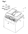
Fig. 1 is a perspective view of a multifunction apparatus according to an illustrative embodiment, in which an automatic document feeder (ADF) is in a closed state; -
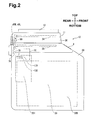
Fig. 2 is a left side view of the multifunction apparatus; -
Fig. 3 is a rear view of the multifunction apparatus; -
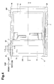
Fig. 4 is a top view of the multifunction apparatus; -
Fig. 5 is a perspective view of the multifunction apparatus, in which the ADF is in an open state; -
Fig. 6 is a cross sectional view of the multifunction apparatus, taken along the line A - A ofFig. 4 ; -
Fig. 7 is a block diagram illustrating an internal structure of the multifunction apparatus; -
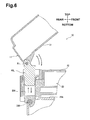
Fig. 8 is a cross sectional view of the multifunction apparatus, taken along the line B - B ofFig. 4 ; -
Fig. 9 is a cross sectional view of the multifunction apparatus, in which the ADF is closed, taken along the line C - C ofFig. 4 ; -
Fig. 10 is a perspective view of a guide unit of the multifunction apparatus; -
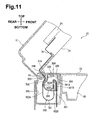
Fig. 11 is a cross sectional view of the multifunction apparatus, in which the ADF is in the open state, taken along the line C - C ofFig. 4 ; -
Fig. 12 is an enlarged perspective view of the multifunction apparatus illustrating the guide unit and a cover portion when the ADF is open; -
Fig. 13 is a cross sectional view of the multifunction apparatus, taken along the line C - C ofFig. 4 , in which the ADF is spaced upwardly apart from the multifunction apparatus; -
Fig. 14 is a cross sectional view of the multifunction apparatus where a guide unit is being inserted in an opening of the multifunction apparatus; -
Fig. 15 is a perspective view illustrating a routing layout of the flexible flat cable, a main unit-side flexible flat cable and a wiring cable in the multifunction apparatus; -
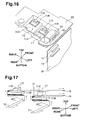
Fig. 16 is a perspective view of a contact prevention mechanism of the multifunction apparatus; and -
Fig. 17 is a diagrammatic sketch of the contact prevention mechanism of the multifunction apparatus. - An illustrative embodiment of the invention will be described in detail with reference to the accompanying drawings.
- As shown in
Fig. 1 , amultifunction apparatus 10 is capable of performing an image reading process in which an image of a document is read and converted into electronic data, an image forming process in which an image is formed on a recording medium (e.g. a sheet of paper or transparency) based on the electronic data, a communication process where the electronic data is transmitted to and received from an external device, and other processes. When the image reading process is activated, themultifunction apparatus 10 may operate as an image reading apparatus. InFig. 1 , a side of themultifunction apparatus 10 having anoperation panel 3 is referred to as the front or front side of themultifunction apparatus 10, and an opposite side is referred to as the rear or rear side of themultifunction apparatus 10. The top or upper side, the bottom or lower side, the left or left side, the right or right side, the front or front side, and the rear or rear side of themultifunction apparatus 10 are identified as indicated by the arrows inFig. 1 . With regard to various individual objects of the multifunction apparatus 1, sides of the individual objects are similarly identified based on the arranged/attached position of the object on/in themultifunction apparatus 10. - The general structure of the
multifunction apparatus 10 will be described. - As shown in
Figs. 1 - 5 , themultifunction apparatus 10 includes amain unit 20, and an automatic document feeder (ADF) 11. TheADF 11 is an example of an openable unit of the invention. - As shown in
Figs. 1 - 4 , theADF 11 is disposed above themain unit 20 so as to cover the top surface of themain unit 20. As shown inFigs. 2 - 5 , a pair ofhinge members main unit 20 and a lower end of the rear side of theADF 11 and spaced apart from each other in the right-left direction. TheADF 11 is configured to pivot around a rotation axis R1 extending in the right-left direction via thehinge members main unit 20. By raising or lowering the front portion of theADF 11, theADF 11 is configured to move between an open state with respect to themain unit 20 shown inFig. 1 and a closed state shown inFig. 5 . When theADF 11 is in the open state, the top surface of themain unit 20 is exposed. - In this embodiment, while the
hinge member 49R corresponds to a normal hinge mechanism that only permits the pivotal movement around the rotation axis R1, thehinge member 49L includes a known free stop function (not shown). By the free stop function, theADF 11 can be brought to a stop at an angle between the open state and the closed state. TheADF 11 has center of gravity G shifted to the left as shown inFig. 3 because afeeder 42 is located on the left side. Thus, thehinge member 49L having the free stop function is located vertically downward relative to a line passing through the center of gravity G and extending in the front-rear direction. When viewed from the rear side of themain unit 20 and theADF 11, thehinge member 49L having the free stop function is located along the vertical axis of the center of gravity G (e.g., vertically aligned with the center of gravity G). With this location, thehinge 49L supports the weight of theADF 11 in balance, which facilitates the movement of theADF 11 between the open state and the closed state and allows theADF 11 to stop at an angle during movement between the open state and the closed state. This improves a degree of ease of operation by the user in moving theADF 11 with respect to themain unit 20. Additionally, thehinge member 49L is separated from aleft side surface 20B of the main unit 20 (along which acontrol circuit board 201, which will be later described, is disposed), and thus a flexibleflat cable 7A and a main unit-side flexibleflat cable 7B, which will be described later, can be arranged in an unoccupied space between thehinge member 49L and theleft side surface 20B. - As shown in
Fig. 6 (cross sectional view taken along the line A - A ofFig. 4 ), thehinge member 49L has a columnar portion extending downward and the columnar portion of thehinge member 49L is inserted in aguide hole 20A that is a recessed portion extending downward from the top surface of themain unit 20 on the rear side, allowing thehinge member 49L to move up and down in theguide hole 20A with respect to themain unit 20. Although not shown, thehinge member 49R also has a columnar portion extending downward in similar fashion to thehinge member 49L. The columnar portion of thehinge member 49R is inserted in anotherguide hole 20A recessed in themain unit 20, allowing thehinge member 49R to move up and down in theguide hole 20A relative to themain unit 20. TheADF 11, which is connected to themain unit 20 via thehinge members main unit 20. - The
main unit 20 will be described. - As shown in
Fig. 1 , the front side of themain unit 20 includes theoperation panel 3. Theoperation panel 3 is configured to receive input from a user and display a processing status of and other information relating to themultifunction apparatus 10. As shown inFigs. 2 and3 , themain unit 20 includes animage forming unit 29 that is configured to form an image on a recording medium, e.g., a sheet of paper or a transparency sheet. As theimage forming unit 29, an electrophotographic type, an inkjet type, and other known types can be mountable, and a detailed description thereof will be omitted. Once an image has been formed on a recording medium by theimage forming unit 29, the recording medium is ejected toward a main unit-side ejection tray 29A (Fig. 1 ), which opens to the front side of themain unit 20 under theoperation panel 3 and extends generally horizontally toward the rear side. Although not described in detail, as shown inFig. 6 , the rear side of themain unit 20 includes a main unit-side hinge member 29B positioned generally level with the main unit-side ejection tray 29A. An upper portion of themain unit 20 above the main unit-side ejection tray 29A is pivotally connected to a lower portion of themain unit 20 below the main unit-side ejection tray 29A via the main unit-side hinge member 29B. - As shown in a block diagram of
Fig. 7 , themain unit 20 includes acontrol circuit board 201 serving as a processing portion that performs controls for structural elements within theADF 11, theoperational panel 3 andimage forming unit 29, apower supply portion 202 that supplies power to each structural element, and acommunication portion 203 that communicates with external devices via LAN and telephone lines. - As shown in
Figs. 2 and3 , thecontrol circuit board 201 is disposed inside themain unit 20 and generally parallel to aleft side surface 20B of themain unit 20. To shrink the size of the apparatus, the space between thecontrol circuit board 201 and theleft side surface 20B of themain unit 20 is narrowed. A readingportion 24 to be described later is disposed closer toleft side surface 20B of themain unit 20 than to the right side surface of themain unit 20. Additionally, since electromagnetic noise may occur from thepower supply portion 202, thepower supply portion 202 is shielded from electromagnetic noise to some degree and disposed apart from thecontrol circuit board 201 and thecommunication portion 203. - As shown in
Figs. 5 and8 , the top side of themain unit 20 includes acontact glass 22. Thecontact glass 22 includes afirst glass 79 on the left, and a second glass on the right. Thefirst glass 79 is used when an image is read by a main unit-side reading portion 25 at a fixed position. Thesecond glass 80 is used when an image is read by the main unit-side reading portion 25 which moves. Adocument separation member 81 is interposed between thefirst glass 79 and thesecond glass 80. Thesecond glass 80 includes a surface facing upward, where the upward facing surface functions as adocument receiving surface 22A on which a document (in the form of a sheet or book) to be read is received or placed. - As shown in
Figs. 7 and8 , an interior of themain unit 20 includes a main unit-side reading portion 25, which is disposed under thecontact glass 22. As the main unit-side reading portion 25, a known image reading sensor, such as a contact image sensor (CIS) and a charge coupled device (CCD), can be used. In this embodiment, a CIS is used. As shown inFig. 8 , the interior of themain unit 20 includes aslide shaft 78 which extends in a left-right direction and is fixed to inner side surfaces of a casing of themain unit 20. The main unit-side reading portion 25 is slidably supported by theslide shaft 78. During standby, the main unit-side reading portion 25 is located under the left end of thesecond glass 80. The main unit-side reading portion 25 is configured to slide in the left-right direction (which is a sub scanning direction of the main unit-side reading portion 25) along theslide shaft 78 as a pulley belt mechanism (not shown) is driven based on control signals from thecontrol circuit board 201. - As shown in
Fig. 3 , in a standby state, the main unit-side reading portion 25 is located closer to the upper portion of thecontrol circuit board 201. When viewed from above, the main scanning direction (in the front-rear direction, viewed from the front side of the drawing sheet ofFig. 3 toward the back side thereof) of the main unit-side reading portion 25 is shifted from the main scanning direction of the readingportion 24. Specifically, the main unit-side reading portion 25 is disposed closer to thehinge member 49L rather than the readingportion 24, and the readingportion 24 is shifted to the left and spaced a specified distance apart from the main unit-side reading portion 25. As will be described later, this arrangement facilitates routing layout of a main unit-side flexibleflat cable 7B such that it extends downward along and on the right side of the flexibleflat cable 7A. As a result, an overlap section between L1 and L2, which will be described later, can be shortened. - When the user puts a document or a book open on the
second glass 80 to read an image formed on a surface of the document or the book facing thesecond glass 80, that is, when automatic document reading operation of theADF 11 is not used, the main unit-side reading portion 25 moves from the left end to the right end under thesecond glass 80 to read the image formed on the surface of the document or the book. The output signals (including image data) of the main unit-side reading portion 25 are transmitted to thecontrol circuit board 201 via the main unit-side flexibleflat cable 7B, which electrically connects the main unit-side reading portion 25 and thecontrol circuit board 201 in themain unit 20, as shown inFig. 7 . Based on the output signals of the main unit-side reading portion 25, thecontrol circuit board 201 creates print data for the image of the document or controls theimage forming unit 29 to perform controls for forming an image on a recording medium. - The
ADF 11 will be described. - As shown in
Fig. 8 , theADF 11 includes adocument tray 12 and anoutput tray 14, which are arranged vertically. Thedocument tray 12 is configured to receive a stack of sheets, as documents, to be read. Theoutput tray 14 is configured to receive ejected sheets. - The
ADF 11 further includes afeeder 42 and the readingportion 24. Thefeeder 42 is configured to pick up asingle sheet 9 from sheets placed on thedocument tray 12 and automatically feed the sheet along afeed path 16 to theoutput tray 14. The readingportion 24 is configured to read an image formed on afirst surface 9A of thesheet 9 in a middle of thefeed path 16. It is noted that thefirst surface 9A faces down when thesheet 9 is placed on thedocument tray 12, and an opposite side to thefirst surface 9A is referred to as asecond surface 9B. - The
feeder 42 will be described. - In the
feeder 42, thefeed path 16 is defined by afirst feed path 26, acurved feed path 27, and asecond feed path 28. Thefirst feed path 26 extends from thedocument tray 12 to the left. Thecurved feed path 27 connects to thefirst feed path 26 and is curved in an arc from thefirst feed path 26 downward. Thesecond feed path 28 connects to thecurved feed path 27 and extends from thecurved feed path 27 to the upper right toward theoutput tray 14. - The
feeder 42 includes afeeder body frame 30, anupper guide 34, alower guide 36, and anupper cover 32. Thefeeder body frame 30, theupper guide 34, and thelower guide 36 make up a base member. Theupper cover 32 covers a left part of theupper guide 34. Thefeeder body frame 30 is a box-shaped and constitutes a bottom surface and side surfaces of theADF 11. Theupper guide 34 defines a part of thefirst feed path 26 and is shaped like a plate which extends from thedocument tray 12 to a location close to asupply unit 50. Thelower guide 36 defines a part of thesecond feed path 28 and is shaped like a plate extending from below amain roller 64 to a location close to anejection unit 70. - The left end of the
upper cover 32 is pivotally supported by the left end of thefeeder body frame 30. Although not shown, when the right end of theupper cover 32 is raised, the top of thefirst feed path 26 is exposed such that cleaning around the readingportion 24 and clearing of paper jamming can be performed. - The
upper cover 32 includes inside reinforcingribs upper cover 32 closed, the reinforcingribs upper cover 32 to the left end thereof. The reinforcingribs upper cover 32 are configured to guide an upper surface of the sheet fed from thedocument tray 12 and constitute a part of thefirst feed path 26 and thecurved feed path 27. - The
main roller 64 is disposed at the left end of thefeeder body frame 30 and under the left end of the reinforcingrib 191. The inner wall surface of thefeeder body frame 30 at the left end, the left ends of the reinforcingribs main roller 64 are configured to guide a sheet fed through thefirst feed path 26 toward a downstream side in a sheet feeding direction. In other words, the inner wall surface of thefeeder body frame 30 at the left end, the left ends of the reinforcingribs main roller 64 constitute thecurved feed path 27. - A lower portion of the inner wall surface of the
feeder body frame 30 and thelower guide 36 are configured to guide a sheet fed through thecurved feed path 27 toward theoutput tray 14. In other words, the inner wall surface of thefeeder body frame 30 at the lower side and thelower guide 36 constitute thesecond feed path 28. As shown inFigs. 5 and8 , alower surface 31 of thefeeder body frame 30 of theADF 11 includes anopening 84. Theopening 84 is located in a boundary between thecurved feed path 27 and thesecond feed path 28. When the sheet passes theopening 84, the sheet fed through thesecond feed path 28 is exposed to themain unit 20 at theopening 84. - The sheet fed from the
curved feed path 27 toward thesecond feed path 28 passes through theopening 84 over thefirst glass 79 disposed in themain unit 20. At this time, thedocument separation member 81, which is disposed between thefirst glass 79 and thesecond glass 80, separates the sheet from thefirst glass 79 and reliably guides the sheet toward thesecond feed path 28. - As shown in
Fig. 8 , thefeeder 42 includes thesupply unit 50, afeeding unit 60, and anejection unit 70. - The
supply unit 50 is disposed downstream from thedocument tray 12 in the sheet feeding direction, and is configured to pick up a sheet from thesheets 9 placed on thedocument tray 12 and supply the sheet toward a downstream side. Thesupply unit 50 includes apickup roller 52 disposed above theupper guide 34, a separation roller 54, and aseparation pad 57. - The separation roller 54 is disposed in the middle of a first rotation shaft 56 which is rotatably supported at its front and rear ends by the
feeder body frame 30. The first rotation shaft 56 is driven by a drive source 99 (shown inFigs. 2 ,3 ,4 , and7 ) comprised of an electric motor and gears, and rotates in a predetermined direction (clockwise inFig. 8 ). Accordingly, the separation roller 54 rotates along with the first rotation shaft 56. - The first rotation shaft 56 pivotally supports a
holder 58. Theholder 58 encloses the separation roller 54 and extends toward thedocument tray 12. Theholder 58 rotatably supports thepickup roller 52 in the extending portion. Thepickup roller 52 is coupled to the first rotation shaft 56 via gears (not shown) disposed in theholder 58. Thus, when the first rotation shaft 56 rotates, not only does the separation roller 54 rotate, thepickup roller 52 also rotates in a clockwise direction. Accordingly, theholder 58 is configured to pivot so as to press thepickup roller 52 down toward theupper guide 34. - The separation roller 54 faces the
separation pad 57. Theseparation pad 57 is pressed against the separation roller 54 from below. Theseparation pad 57 is typically formed of a suberic material and is configured to slidably contact afirst surface 9A of a sheet passing on theseparation pad 57 and to exert a great frictional force against the sheet. - The
pickup roller 52 is configured to rotate while in contact with asecond surface 9B of the sheet placed on thedocument tray 12 to apply a force to the sheet. The separation roller 54 is configured to rotate while in contact with thesecond surface 9B of the sheet fed by the pick uproller 52 to apply a force to the sheet. When a few sheets are passing between the separation roller 54 and theseparation pad 57, only the uppermost sheet in contact with the separation roller 54, is separated from the sheets due to the frictional force of theseparation pad 57, and fed to a downstream side in the sheet feeding direction. The sheet is fed between thepickup roller 52 and theupper guide 34 and between the separation roller 54 and theseparation pad 57, thesupply unit 50 constitutes thefirst feed path 26 along with theupper guide 34 and the reinforcingribs upper cover 32. - The
feeding unit 60 is configured to feed the sheet picked up from thedocument tray 12 by thesupply unit 50 along thecurved feed path 27 and thesecond feed path 28. Thefeeding unit 60 includes afeed roller 61 and apinch roller 65. Thefeed roller 61 is disposed on the left of the separation roller 54 (on a downstream side in the sheet feeding direction from the separation roller 54 in the middle of the first feed path 26). Thepinch roller 65 is disposed facing thefeed roller 61. Thefeeding unit 60 further includes themain roller 64, which is disposed in thecurved feed path 27, andpinch rollers main roller 64. - The
feed roller 61 is disposed in the middle of asecond rotation shaft 66 which is rotatably supported at its front and rear ends by thefeeder body frame 30. Thesecond rotation shaft 66 is driven by thedrive source 99 and rotates in a predetermined direction (clockwise direction inFig. 8 ), as with the first rotation shaft 56. Accordingly, thefeed roller 61 rotates along with thesecond rotation shaft 66. - The sheet fed by the separation roller 54 is nipped by the
feed roller 61 and thepinch roller 65. Thefeed roller 61 is configured to rotate while in contact with thesecond surface 9B of the sheet to apply a force to the sheet. Thefeed roller 61 and thepinch roller 65 also constitute thefirst feed path 26. - The
main roller 64 is disposed around athird rotation shaft 67 which is rotatably supported at its front and rear ends by the feedermain frame 30. Thethird rotation shaft 67 is driven by thedrive source 99 and rotates in a predetermined direction (clockwise direction inFig. 8 ) as with the first andsecond rotation shafts 56, 66. Accordingly, themain roller 64 rotates along with thethird rotation shaft 67. - When the sheet fed by the
feed roller 61 passes over the readingportion 24, the sheet is nipped by themain roller 64 and thepinch roller 62, and subsequently nipped by themain roller 64 and thepinch roller 63 on the downstream side in the sheet feeding direction. Themain roller 64 rotates while in contact with thefirst surface 9A of the sheet, thereby applying a force to the sheet, and feeds the sheet toward the downstream side of thesecond feed path 28. Themain roller 64 and thepinch rollers curved feed path 27 along with the left inner wall surface of the feedermain frame 30 and the left ends of the reinforcingribs upper cover 32. - The
ejection unit 70 is configured to eject the sheet, which is fed through thesecond feed path 28 by thefeeding unit 60, to theoutput tray 14. Theejection tray 70 includes anejection roller 72 and apinch roller 74, which are disposed on the right end of the lower guide 36 (on the downstream side of the second feed path 28). Theejection roller 72 is disposed around afourth rotation shaft 71 of which is rotatably supported at its front and rear ends by the feedermain frame 30. Thefourth rotation shaft 71 is driven by thedrive source 99 and rotates in a predetermined direction (counterclockwise direction inFig. 8 ), as with the first, second andthird rotation shafts ejection roller 72 rotates along with thefourth rotation shaft 71. The sheet fed along thesecond feed path 28 is nipped by theejection roller 72 and thepinch roller 74, and ejected to theoutput tray 14. Theejection roller 72 and thepinch roller 74 constitute thesecond feed path 28 along with the inner bottom surface of the feedermain frame 30 and thelower guide 36. - As with the main unit-
side reading portion 25, the readingportion 24 uses a contact image sensor (CIS). The readingportion 24 is disposed on the downstream side from thefeed roller 61 in the sheet feeding direction such that its reading surface faces thefirst feed path 26. In thefirst feed path 26, the readingportion 24 is disposed downstream from thefeed roller 62 and upstream from themain roller 64, and thefirst surface 9A of the sheet fed in thefirst feed path 26 passes over the top surface of the readingportion 24. The main scanning direction of the readingportion 24 is parallel to theleft side surface 20B of themain unit 20 and the readingportion 24 is disposed closer to theleft side surface 20B than the right side in the left-right direction. - A
white member 76 is disposed above the readingportion 24. Thewhite member 76 is elastically urged by a coil spring toward the readingportion 24. While being pressed toward the readingportion 24 by thewhite member 76, the sheet fed from thefeed roller 61 passes the top surface of the readingportion 24. Thewhite member 76 and the top surface of the reading portion 24 (a glass member covering the top of the image sensor) also constitute thefirst feed path 26. The output signals (including image data) of the readingportion 24 are transmitted to thecontrol circuit board 201 via the flexibleflat cable 7A disposed between theADF 11 and themain unit 20, as shown inFig. 7 . Thecontrol circuit board 201 creates print data to print an image on thefirst surface 9A of the sheet based on the output signals of the readingportion 24, or controls theimage forming unit 29, and performs various controls for forming an image on a recording medium. - When the
ADF 11 operates, the main unit-side reading portion 25 moves to an image reading position 18 (Fig. 8 ) and stops there. In this state, the top surface of the main unit-side reading portion 25 faces thesecond feed path 28 via theopening 84. The sheet fed by thefeeding unit 60 reaches theimage reading position 18 on thefirst glass 79. At this point in time, thesecond surface 9B of the sheet passes over the top surface of the main unit-side reading portion 25. The sheet is separated from thefirst glass 79 by thedocument separation member 81. - The
white member 82 is located opposite to the main unit-side reading portion 25 when the main unit-side reading portion 25 is standing by in theimage reading position 18 via thefirst glass 79. Thewhite member 82 is elastically urged by the coil spring toward the main unit-side reading portion 25 standing by in theimage reading position 18. The sheet fed along thesecond feed path 28 passes over the top surface of the main unit-side reading portion 25 while being pressed toward the main unit-side reading portion 25 by thewhite member 82. The main unit-side reading portion 25 reads the image formed on thesecond surface 9B of the sheet. The output signals of the main unit-side reading portion 25 are transmitted to thecontrol circuit board 201 via the main unit-side flexibleflat cable 7B. Thecontrol circuit board 201 performs various controls described above. Thefirst glass 79 and thewhite member 82 constitute thesecond feed path 28 through which the sheet passes. - Automatic document reading operation of the
ADF 11 will be described. - As shown in
Fig. 8 , the user places one ormore sheets 9 on thedocument tray 12 such that leading ends of thesheets 9 are inserted into thesupply unit 50. When the user operates theoperation panel 3 to start automatic document reading by theADF 11, thecontrol circuit board 201 controls thefeeder 42 and the readingportion 24 in theADF 11 to begin an automatic document reading operation. Thesheets 9 placed on thedocument tray 12 are individually (e.g., a single sheet at a time) picked up and fed along thefeed path 16. In thefirst feed path 26, an image formed on thefirst surface 9A is read by the readingportion 24. The sheet is further fed along thefeed path 16, and when the sheet passes thecurved feed path 27, it is inverted. Thesecond surface 9B of the sheet faces downward in thesecond feed path 28. An image formed on thesecond surface 9B is read by the main unit-side reading portion 25, and the sheet is ejected to theoutput tray 14. This operation is automatically repeated until no sheets remain on thedocument tray 12. - As shown in
Figs. 2 ,3 , and7 , themultifunction apparatus 10 includes the flexibleflat cable 7A and the main unit-side flexibleflat cable 7B. The flexibleflat cable 7A is configured to electrically connect the readingportion 24 of theADF 11 and thecontrol circuit board 201 of themain unit 20 and to transmit the output signals of the readingportion 24 to thecontrol circuit board 201. The main unit-side flexibleflat cable 7B is configured to electrically connect the main unit-side reading portion 25 and thecontrol circuit board 201 in themain unit 20 and to transmit the output signals of the main unit-side reading portion 25 to thecontrol circuit board 201. - The flexible
flat cable 7A and the main unit-side flexibleflat cable 7B are cables with multi thin covered conductors united into a strip. Generally, flexible flat cables are susceptible to damage such as breaks due to excessive twisting and repeated bending or pulling, and are sensitive to static electricity and electromagnetic wave noise (which, for example, may leak from thepower supply portion 202 and the drive source 99). Thus, in this embodiment, a routing layout described below is used for the flexibleflat cable 7A and the main unit-side flexibleflat cable 7B. - As shown in
Figs. 2 and9 (cross sectional view taken along the line C - C ofFig. 4 ), the upper end of the flexibleflat cable 7A is connected to an end on the rear side of the readingportion 24 whose main scanning direction is the front-rear direction. As shown inFig. 9 , the flexibleflat cable 7A extends from the end on the rear side of the readingportion 24 toward the bottom surface of theADF 11, and extends along a bottom portion of the feedermain frame 30 of theADF 11 toward the rear side of theADF 11. The flexibleflat cable 7A further extends downward through acable insertion hole 31 B formed in the bottom portion on the rear side of the feedermain frame 30 toward anopening 20C formed in the top surface on the rear side of themain unit 20. Thecable insertion hole 31 B is long and thin in the left-right direction and is formed slightly longer than a width of the flexibleflat cable 7A. Thecable insertion hole 31 B is formed longer than a thickness of the flexibleflat cable 7A in the front-rear direction. Thus, the flexibleflat cable 7A is smoothly movable in thecable insertion hole 31B and is prevented from being twisted. The lower end on the rear side of theADF 11 integrally includes acover portion 31 A. Thecover portion 31 A is disposed in front of thecable insertion hole 31B, is shaped like a plate, and protrudes downward. - As shown in
Fig. 12 , theopening 20C is rectangularly shaped, located to the left of thehinge member 49L, and positioned slightly to the right of the center of thefirst glass 79. As shown inFig. 9 , theopening 20C has a depth (internal space) downward in which aguide unit 300 is inserted. The internal space is defined in the frame constituting themain unit 20. Even with theguide unit 300 inserted, the internal space has a further space extending rearward and downward, which is referred to as acable storing portion 20D. - As shown in
Figs. 9 and 10 , theguide unit 300 includes alid portion 309, aside wall portion 308 extending downward from the right end of thelid portion 309, and arib 301 protruding leftward from the front end of theside wall portion 308. As shown inFig. 12 , with theguide unit 300 inserted in theopening 20C, thelid portion 309 is flush with the top surface of themain unit 20. Therib 301 is generally shaped like a flat plate which is vertical relative to thelid portion 309. Therib 301 has anupper end 301A, which is vertically spaced apart from thelid portion 309 and is bent downward. - The
guide unit 300 includes aspace holding portion 302, which is attached to and extends from the rear end of theside wall portion 308 and protrudes leftward. Thespace holding portion 302 is spaced apart from and facing therib 301 in the front-rear direction. The upper end of thespace holding portion 302 is connected to the rear end of thelid portion 309. Thespace holding portion 302 includes a generallyflat portion 302A and a generallycylindrical portion 302B. The generallyflat portion 302A is generally shaped like a flat plate, which is vertical relative to thelid portion 309, and extends downward from thelid portion 309. The generallycylindrical portion 302B is connected to the generallyflat portion 302A and has a cylindrical shape or C-shape. The generallycylindrical portion 302B is not closed in a circumferential direction, and anend 302C of the generallycylindrical portion 302B is vertically spaced apart from and facing theupper end 301A of therib 301. The generallycylindrical portion 302B protrudes further rearward than the generallyflat portion 302A. This protruding portion makes anescape portion 303 above the generallycylindrical portion 302B and at the rear of the generallyflat portion 302A. In theguide unit 300, a side surface opposite to theside wall portion 308 via therib 301 and thespace holding portion 302 is exposed. - As shown in
Fig. 9 , the flexibleflat cable 7A, which hangs down through thecable insertion hole 31B toward theopening 20C, passes through theescape portion 303, is routed along the rear surface of thespace holding portion 302, extends vertically, and is curved upward in the vicinity of the bottom portion of thecable storing portion 20D. In theescape portion 303, thecover portion 31A is located between the flexibleflat cable 7A and the rear surface of thespace holding portion 302. - The flexible
flat cable 7A is further routed along the front surface of thespace holding portion 302, extends generally vertically upward, and passes between thetermination 302C of thespace holding portion 302 and theupper end 301A of therib 301. Then, the flexibleflat cable 7A changes its course downward along the shape of theupper end 301A. The flexibleflat cable 7A is routed along the front surface of therib 301, and extends further downward generally vertically. The flexibleflat cable 7A is fixed to the front surface of therib 301 with a double-faced tape 301B. - As shown in
Fig. 9 , therib 301 fixes a predetermined portion of the flexibleflat cable 7A and holds the flexibleflat cable 7A to allow slack therein between the fixed portion and thecable insertion hole 31B in a U-shape when viewed along the left-right direction (the rotation axis R1). Accordingly, a generallyU-shaped slack portion 700 can be secured. Thespace holding portion 302 supports the generallyU-shaped slack portion 700 such that generallystraight portions curved portion 701, are spaced a predetermined distance apart. The predetermined distance is set so as to maintain that the curvature of thecurved portion 701 equals or exceeds a curvature that prevents damage such as breaks even if the flexibleflat cable 7A is repeatedly bent. An antistatic member 709 (for example, a known antistatic tape) covers a portion of the flexibleflat cable 7A that is on a side closer to the generallystraight portion 702A than the generallystraight portion 702B and may be exposed outside by vertical movement of theADF 11. - As shown in
Fig. 11 , when theADF 11 pivots around the rotation axis R1 and is positioned in the open state with respect to themain unit 20, theguide unit 300 raises the generallystraight portion 702A, which is closer to theADF 11 than the generallystraight portion 702B, while maintaining the shape of thecurved portion 701 of the flexibleflat cable 7A at thespace holding portion 302. At this time, as the generallystraight portion 702A is moved upward, thecurved portion 701 is pulled upward. However, the curvature of thecurved portion 701 can be maintained such that the curvature is greater than or equal to the specified curvature because thespace holding portion 302 maintains the distance between the opposed generallystraight portions ADF 11 pivots around the rotation axis R1, the lower end of theADF 11 on the rear side, the flexibleflat cable 7A and thecover portion 31 A move frontward. However, as theguide unit 300 includes theescape portion 303, the lower end of theADF 11 on the rear side, the flexibleflat cable 7A and thecover portion 31A can enter theescape portion 303. In other words, the formation of theescape portion 303 can provide for a space that the lower end of theADF 11 on the rear side, the flexibleflat cable 7A and thecover portion 31A can enter, without having to increase the size of the apparatus in the front-rear direction, and reliably reduce the possibility of the flexibleflat cable 7A being caught between the lower end of theADF 11 and thecover portion 31A. - As shown in
Fig. 12 , when theADF 11 is in the open state, thecover portion 31A covers the flexibleflat cable 7A from the front side. Thus, exposure of the flexibleflat cable 7A to the front side of themain unit 20 can be eliminated and the flexibleflat cable 7A can be reliably protected. - As shown in
Fig. 13 , when theADF 11 moves up with respect to themain unit 20, the generallystraight portion 702A, which is on the side close to theADF 11, and thecurved portion 701 of the flexibleflat cable 7A are moved upward. When the generallystraight portion 702A moves up, thecurved portion 701 is pulled upward. However, as thecurved portion 701 moves along thecylindrical portion 302B of thespace holding portion 302, the curvature of thecurved portion 701 can be maintained so as to be greater than or equal to the predetermined curvature. Even when the generallystraight portion 702A, which is on the side close to theADF 11, moves up and its surface is exposed outside, the surface is covered by theantistatic member 709. Without hindering the movement of the flexibleflat cable 7A, theantistatic member 709 protects the flexibleflat cable 7A from electrostatic discharge and contact. - The
guide unit 300 is configured to guide the flexibleflat cable 7A such that the flexibleflat cable 7A can follow the pivotal or vertical movement of theADF 11. As thespace holding portion 302 can prevent the curvature of thecurved portion 701 from becoming too small, the flexibleflat cable 7A can be prevented from damage caused by being excessively bent. As the flexibleflat cable 7A is fixed at the predetermined portion to the front surface of therib 301 with the double-faced tape 301B, the flexibleflat cable 7A is not displaced with respect to theguide unit 300. When theADF 11 pivots or moves up or down with respect to themain unit 20, thespace holding portion 302 can guide the flexibleflat cable 7A reliably. - The
guide unit 300 is provided separately from themain unit 20. As shown by a chain double-dashed line inFig. 14 , the flexibleflat cable 7A is previously fixed to therib 301 of theguide unit 300 with the double-faced tape 301B, and then theguide unit 300 is combined with theADF 11. When theguide unit 300 is viewed from the rotation axis R1, the side surface opposite to theside wall portion 308 via therib 301 and thespace holding portion 302 is released. The flexibleflat cable 7A can be easily inserted into theguide unit 300 from the released side surface. Thus, the flexibleflat cable 7A can be easily routed along thespace holding portion 302 and therib 301 and fixed to the front surface of therib 301 with the double-faced tape 301B. When theADF 11 is attached to themain unit 20, the columnar portions of thehinge members Fig. 6 ) are inserted into the guide holes 20A, the lower end side of the flexibleflat cable 7A is inserted into theopening 20C and thecable storing portion 20D, and then guideunit 300 is inserted into theopening 20C from the released side (front side) of theADF 11 and mounted therein. In this manner, theguide unit 300 can be easily fitted into theopening 20C, which achieves simplification of the assembly operation. The flexibleflat cable 7A can be easily replaced with a new cable by removing theguide unit 300 from theopening 20C. - The following will describe the routing layout of the flexible
flat cable 7A which extends below the point at which the flexibleflat cable 7A is fixed to therib 301. - As shown in
Fig. 15 , the flexibleflat cable 7A runs along the front surface of therib 301, extends downward in a generally straight fashion, changes its course rearward shortly, then changes its direction downward shortly and reaches the top of aframe member 20E (Fig. 16 ) disposed inside themain unit 20. As shown inFig. 16 , theframe member 20E is dish-shaped and extends horizontally. A left end of theframe member 20E is positioned above the upper end of thecontrol circuit board 201. A first holdingmember 111 is formed in the middle of theframe member 20E, and asecond holding member 112 is formed on the right side of the first holdingmember 111. Afirst ferrite core 121 is disposed on the left side of the first holdingmember 111, and asecond ferrite core 122 is disposed on top of thefirst ferrite core 121 in layers. - The first and second holding
members second ferrite cores - In
Fig. 15 , theframe member 20E is omitted for the sake of clarity of routing layout of the flexibleflat cable 7A. InFig. 15 , it is assumed that the first holdingmember 111 provided in theframe member 20E shown inFig. 16 is located directly under aportion 711 where the flexibleflat cable 7A changes its course frontward. - As shown in
Fig. 16 , the first holdingmember 111 includes afirst step portion 111 A, a firstflat portion 111B, and a firstpressing portion 111C. Thefirst step portion 111A is recessed downward with respect to the top surface of theframe member 20E. The firstflat portion 111B is disposed above thefirst step portion 111A. The firstpressing portion 111C is disposed above the firstflat portion 111B. As shown inFig. 17 , the flexibleflat cable 7A extends over thefirst step portion 111A toward the front from theportion 711 where the flexibleflat cable 7A changes its course frontward, then is twisted and bent at an angle of 45 degrees and changes its course rightward under the firstflat portion 111B. The flexibleflat cable 7A is bent further along the right side surface and the top surface of the firstflat portion 111B in a generally U-shape, and extends leftward. With this state, the flexibleflat cable 7A is vertically caught between the firstpressing portion 111C and the firstflat portion 111B. Accordingly, thefirst holding portion 111 can route the flexibleflat cable 7A toward thecontrol circuit board 201 and fix the flexibleflat cable 7A. - As shown in
Fig. 15 , the flexibleflat cable 7A is inserted into thefirst ferrite core 121. Thefirst ferrite core 121 is configured to attenuate noise included in electrical signals transmitted by the flexibleflat cable 7A. Then, the flexibleflat cable 7A extends above thecontrol circuit board 201, and changes its course downward. Afirst connector 131, which is flat and used for the flexibleflat cable 7A, is disposed in an upper portion of a surface of thecontrol circuit board 201 facing leftward. The flexibleflat cable 7A is inserted into thefirst connector 131 from above and thus is electrically connected to thefirst connector 131. - As shown in
Fig. 2 , the upper end of the main unit-side flexibleflat cable 7B is connected to the end portion of the main unit-side reading portion 25 on the rear side. The main scanning direction of the main unit-side reading portion 25 is the front-rear direction. As shown inFig. 15 , after extending to the rear side of themain unit 20, the main unit-side flexibleflat cable 7B extends downward in a generally straight fashion. At this point, the main unit-side flexibleflat cable 7B is disposed in parallel with and to the right of the flexibleflat cable 7A (Fig. 3 ). The main unit-side flexibleflat cable 7B subsequently changes its course rearward shortly, then changes its course downward shortly, and reaches the top of theframe member 20E (Fig. 16 ). - In
Fig. 15 , theframe member 20E is omitted for the sake of clarity of the routing layout of the main unit-side flexibleflat cable 7B. InFig. 15 , it is assumed that the second holdingmember 112 disposed in theframe member 20E shown inFig. 16 is located directly under aportion 721 where the main unit-side flexibleflat cable 7B changes its course frontward. - As shown in
Fig. 16 , the second holdingmember 112 includes asecond step portion 112A, a secondflat portion 112B, and a secondpressing portion 112C. Thesecond step portion 112A is recessed downward with respect to the top surface of theframe member 20E. The secondflat portion 112B is disposed above thesecond step portion 112A. The secondpressing portion 112C is disposed above the secondflat portion 112B. Thesecond holding member 112 is disposed at a higher position than the first holdingmember 111, and arranged alongside of the first holdingmember 111 in a direction toward the control circuit board 201 (in the left-right direction). - As shown in
Fig. 17 , the main unit-side flexibleflat cable 7B extends over thesecond step portion 112A toward the front from theportion 721 where the main unit-side flexibleflat cable 7B changes its course to the front, then is twisted and bent at anangle 45 degrees and changes its course rightward under the secondflat portion 112B. The main unit-side flexibleflat cable 7B is bent further along the right side surface and the top surface of the secondflat portion 112B in a generally U-shape, and extends leftward. With this state, the main unit-side flexibleflat cable 7B is vertically caught between the secondpressing portion 112C and the secondflat portion 112B. Accordingly, thesecond holding portion 112 can route the main unit-side flexibleflat cable 7B toward thecontrol circuit board 201 and fix the main unit-side flexibleflat cable 7B. - The main unit-side flexible
flat cable 7B extends to the left from the second holdingmember 112 and runs parallel to the flexibleflat cable 7A to the left in a state where theflat cables flat cables member 112 is disposed at a position higher than the first holdingmember 111, a space between the flexibleflat cable 7A and the main unit-side flexibleflat cable 7B can be maintained in the thickness direction (vertically), and thus contact between theflat cables pressing portion 111C has sufficient thickness, and the main unit-side flexibleflat cable 7B is placed on the top of the firstpressing portion 111C. Even with this arrangement, the vertical space between theflat cables - As shown in
Fig. 15 , the main unit-side flexibleflat cable 7B is inserted into thesecond ferrite core 122. Thesecond ferrite core 122 is configured to attenuate noise included in the electrical signals transmitted by the main unit-side flexibleflat cable 7B. As thesecond ferrite core 122 is disposed on top of thefirst ferrite core 121, the space between theflat cables flat cables second ferrite cores - The main unit-side flexible
flat cable 7B extends above thecontrol circuit board 201, and changes its course downward. Asecond connector 132, which is flat and used for the main unit-side flexibleflat cable 7B, is disposed in an upper portion of the surface of thecontrol circuit board 201 facing leftward and spaced apart from thefirst connector 131 downwardly. The main unit-side flexibleflat cable 7B is inserted into thesecond connector 132 sideways while being bent in a generally L-shape and thus is electrically connected to thesecond connector 132. The main unit-side flexibleflat cable 7B may be inserted into thesecond connector 132 from below to above. - As shown in
Fig. 15 , a starting point L1 of an overlap section between the flexibleflat cable 7A and the main unit-side flexibleflat cable 7B corresponds to a location at which the flexibleflat cable 7A extends downward from the readingportion 24 in a generally straight fashion and then makes a turn in a horizontal direction that is parallel to the rotation axis R1 (in the left-right direction), or a location at which the flexibleflat cable 7A is held by thefirst holding portion 111. An ending point L2 of the overlap section is a location where the flexibleflat cable 7A is inserted into thefirst connector 131. In this embodiment, bothflat cables second connectors flat cables respective connectors flat cables respective connectors flat cables flat cables respective connectors flat cables respective connectors - As shown in
Figs. 2 ,3 ,7 , and15 , awiring cable 7C is disposed between theADF 11 and themain unit 20. Thewiring cable 7C is configured to electrically connect thefeeder 42 of theADF 11 and thecontrol circuit board 201 of themain unit 20. Thewiring cable 7C is also configured to transmit a control signal from thecontrol circuit board 20 to thedrive source 99 of thefeeder 42 and transmit a detection signal of a document detection sensor included in thefeeder 42 to thecontrol circuit board 201. - As shown in
Fig. 3 , the upper end of thewiring cable 7C is connected to a location which is on the left side of thedrive source 99 and apart from the readingportion 24 and the main unit-side reading portion 25. As shown inFigs. 3 and15 , thewiring cable 7C is routed downward along the inner wall of theleft side surface 20B of themain unit 20 and apart from the flexibleflat cable 7A and the main unit-side flexibleflat cable 7B. Thewiring cable 7C is connected to thecontrol circuit board 201. Thewiring cable 7C is electrically connected to thecontrol circuit board 201 at a location apart from the first andsecond connectors Fig. 3 , when viewed from the rear side of themultifunction apparatus 10, thewiring cable 7C is routed on a side close to theleft side surface 20B, which is closer to the readingportion 24 than the main unit-side reading portion 25, and spaced apart from the flexibleflat cable 7A and the main unit-side flexibleflat cable 7B. Thus, even if noise occurs in thewiring cable 7C on thefeeder 42 side, the flexibleflat cable 7A and the main unit-side flexibleflat cable 7B may be rendered insensitive to the noise. In addition, the route path of thewiring cable 7C on thefeeder 42 side can be shortened. - In the
multifunction apparatus 10, thecontrol circuit board 201 is disposed as described above to narrow the width of theapparatus 10. As shown inFig. 3 , when viewed from the rear side of themultifunction apparatus 10, the flexibleflat cable 7A is disposed closer to a flat surface P than is thehinge member 49L. The flat surface P extends along and parallel to thecontrol circuit board 201. InFig. 3 , the flexibleflat cable 7A is shown from one end connected to the readingportion 24 to theportion 711 where the flexibleflat cable 7A changes its course frontward. In addition, the flexibleflat cable 7A extends vertically straightly between theADF 11 and themain unit 20. Thus, the twisting and bending portions of the flexibleflat cable 7A can be reduced in the routing path from the readingportion 24 of theADF 11 to thecontrol circuit board 201 of themain unit 20. - The reading
portion 24 and thecontrol circuit board 201 are disposed close to each other and the flexibleflat cable 7A is disposed straightly between the readingportion 24 and thecontrol circuit board 201. Thus, the routing path of the flexibleflat cable 7A can be shortened. - Thus, the
multifunction apparatus 10 can reduce damage to the flexibleflat cable 7A such as breaks and noise, and accordingly reduce irregularity in an image during image reading process and image forming process. - In the
multifunction apparatus 10, the readingportion 24 and the flexibleflat cable 7A connected to the readingportion 24, and the main unit-side reading portion 25 and the main unit-side flexibleflat cable 7B connected to the main unit-side reading portion 25 are arranged close to thecontrol circuit board 201, and thus routing paths of both theflat cables flat cables members - In the
multifunction apparatus 10, the readingportion 24 includes a contact image sensor extending in the front-rear direction that is perpendicular to the rotation axis R1. As shown inFig. 9 , one end of the flexibleflat cable 7A is connected to the end on the rear side of the readingportion 24. Thus, the routing path of the flexibleflat cable 7A can be shortened and noise in an output signal of the readingportion 24 transmitted by the flexibleflat cable 7A can be reduced reliably. - The
multifunction apparatus 10 includes two readingportions flat cable 7A and the main unit-side flexibleflat cable 7B are likely to cross each other and the routing layout may become complicated. In particular, if any measures are not taken in themultifunction apparatus 10 where theADF 11 including the readingportion 24 pivots or moves up or down with respect to themain unit 20, the routing path of the flexibleflat cable 7A may become complicated in the vicinity of the rotation axis R1 and the flexibleflat cable 7A may sustain damage such as breakage or result in noise due to being pulled or bent when theADF 11 pivots or moves up or down. In themultifunction apparatus 10, however, the flexibleflat cable 7A is routed as described above, thereby reducing a tendency to cross the flexibleflat cable 7A and the main unit-side flexibleflat cable 7B. Such an arrangement simplifies the routing layout of the flexibleflat cable 7A and the main unit-side flexibleflat cable 7B in themultifunction apparatus 10. In addition, even when theADF 11 pivots or moves up or down around the rotation axis R1, the flexibleflat cable 7A is unlikely to sustain the damage such as breakage, by which the advantageous effect of the invention can be obtained. - In the
multifunction apparatus 10, as the contact prevention mechanism, the first and second holdingmembers second ferrite cores flat cable 7A and the main unit-side flexibleflat cable 7B from contacting each other in the overlap section from L1 to L2. The flexibleflat cable 7A and the main unit-side flexibleflat cable 7B are unlikely to sustain damage such as noise in the signals transmitted by the flexibleflat cable 7A and the main unit-side flexibleflat cable 7B, attributing to contact therebetween. Irregularity in image data of a document may also be reliably prevented. - In the
multifunction apparatus 10, therib 301 of theguide unit 300 holds the generallyU-shaped slack portion 700 of the flexibleflat cable 7A. Thus, even when the flexibleflat cable 7A is pulled with pivotal or vertical movement of theADF 11, the generallyU-shaped slack portion 700 can absorb the positional change in the routing path of the flexibleflat cable 7A and prevent excessive tension on the flexibleflat cable 7A. In addition, the generallyU-shaped slack portion 700 can reduce a tendency to cause the flexibleflat cable 7A to be twisted or bent excessively. Thus, the flexibleflat cable 7A can follow the pivotal or vertical movement of theADF 11 reliably. As a result, the flexibleflat cable 7A is unlikely to sustain damage such as break or noise in a signal transmitted by the flexibleflat cable 7A and thus irregularity in image data of a document can be reliably prevented. - Although an illustrative embodiment and examples of modifications of the present invention have been described in detail herein, the scope of the invention is not limited thereto. It will be appreciated by those skilled in the art that various modifications may be made without departing from the scope of the invention. Accordingly, the embodiment and examples of modifications disclosed herein are merely illustrative. It is to be understood that the scope of the invention is not to be so limited thereby, but is to be determined by the claims which follow.
Claims (13)
- An image reading apparatus comprising:a main unit including:a processing portion; anda guide portion;an openable unit connected to the main unit such that the openable unit pivots around a rotation axis and moves up and down relative to the main unit, the openable unit including:a document tray on which a document is placed;a feeder configured to feed a document placed on the document tray along a feed path; anda reading portion disposed facing the feed path and configured to read an image of the document passing through the feed path; anda flexible flat cable configured to electrically connect the reading portion of the openable unit and the processing portion of the main unit,wherein the processing portion is configured to perform processes relating to image data of the document based on an output signal of at least the reading portion,wherein the guide portion is configured to guide the flexible flat cable such that the flexible flat cable follows pivotal or vertical movement of the openable unit, andwherein the guide portion includes a rib configured to fix a predetermined portion of the flexible flat cable and to hold the flexible flat cable to have a generally U-shaped slack portion between the predetermined portion of the flexible flat cable fixed at the rib and the openable unit when viewed from a direction of the rotation axis of the openable unit.
- The image reading apparatus according to claim 1,
wherein the reading portion is configured to read an image of a first surface formed on the document passing through the feed path,
wherein the main unit includes a main unit-side reading portion disposed facing the feed path, and the main unit-side reading portion is configured to read an image formed on a second surface of the document passing through the feed path, which is opposite to the first surface of the document, and
wherein the processing portion is configured to perform the processes relating to image data for the images formed on the first and second surfaces of the document based on the output signal of the reading portion and an output signal of the main unit-side reading portion. - The image reading apparatus according to claim 1, wherein the guide portion includes a space holding portion configured to hold the flexible flat cable and maintain a predetermined distance between a pair of generally straight portions, which are opposed to each other above a curved portion of the generally U-shaped slack portion, such that a curvature of the curved portion equals or exceeds a predetermined curvature.
- The image reading apparatus according to claim 1,
wherein the guide portion is configured to fix, at the rib, an upper end of a first generally straight portion of the generally straight portions of the flexible flat cable, wherein the first generally straight portion is disposed closer to the processing portion than a second generally straight portion disposed opposite to the first generally straight portion, and to raise or lower the second generally straight portion, which is closer to the openable unit than the first generally straight portion, while maintaining a shape of the curved portion of the flexible flat cable, when the flexible flat cable is pulled by following the movement of the openable unit, and
wherein an antistatic member covers a portion of the flexible flat cable that is on a side closer to the second generally straight portion than to the first generally straight portion, wherein the portion is exposed when the openable unit moves vertically. - The image reading apparatus according to claim 1,
wherein the guide portion includes an escape portion formed on an opposite surface, in a direction perpendicular to the direction of the rotation axis, to the flexible flat cable and a lower end of the openable unit disposed on a side having the rotation axis when the openable unit closes a top surface of the main unit, wherein the flexible flat cable and the lower end of the openable unit disposed on the side having the rotation axis enter the escape portion when the openable unit opens the top surface of the main unit, and
wherein the lower end of the openable unit disposed on the side having the rotation axis integrally includes a cover portion, wherein the cover portion is disposed between the surface and the flexible flat cable opposite to the surface, and is configured to cover the flexible flat cable from an open side of the openable unit when the openable unit opens the top surface of the main unit. - The image reading apparatus according to claim 1,
wherein the main unit includes an opening,
wherein the guide portion is connected to the openable unit via the flexible flat cable fixed to the rib, and
wherein, when the openable unit is attached to the main unit, the opening receives the guide portion. - The image reading apparatus according to claim 6, wherein, when viewed from a direction perpendicular to the direction of the rotation axis, one side of the guide portion is exposed.
- An image reading apparatus comprises:a main unit including:a main unit-side reading portion;a processing portion; anda guide portion;an openable unit connected to the main unit such that the openable unit is pivotable around a rotation axis and moves up and down relative to the main unit, the openable unit including:a document tray on which a document is placed; anda feeder configured to feed a document placed on the document tray along a feed path; anda flexible flat cable configured to electrically connect the openable unit and the processing portion of the main unit;wherein the main unit-side reading portion is disposed facing the feed path and configured to read an image of a document passing through the feed path,wherein the processing portion is configured to perform processes relating to operations of at least the feeder and the main unit-side reading portion,wherein the guide portion is configured to guide the flexible flat cable such that the flexible flat cable follows pivotal or vertical movement of the openable unit, andwherein the guide portion includes a rib configured to fix a predetermined portion of the flexible flat cable and to hold the flexible flat cable to have a generally U-shaped slack portion between the predetermined position of the flexible flat cable fixed at the rib and the openable unit when viewed from a direction of the rotation axis of the openable unit.
- The image reading apparatus according to claim 8, wherein the guide portion includes a space holding portion configured to hold the flexible flat cable and to maintain a predetermined distance between a pair of generally straight portions, which are opposed to each other above a curved portion of the generally U-shaped slack portion, such that a curvature of the curved portion equals or exceeds a predetermined curvature.
- The image reading apparatus according to claim 8,
wherein the guide portion is configured to fix, at the rib, an upper end of a first generally straight portion of the generally straight portions of the flexible flat cable, wherein the first generally straight portion is disposed closer to the processing portion than a second generally straight portion disposed opposite to the first generally straight portion, and to raise or lower the second generally straight portion, which is closer to the openable unit than the first generally straight portion, while maintaining a shape of the curved portion of the flexible flat cable, when the flexible flat cable is pulled by following the movement of the openable unit, and
wherein an antistatic member covers a portion of the flexible flat cable that is on a side closer to the second generally straight portion than to the first generally straight portion, wherein the portion is exposed when the openable unit moves vertically. - The image reading apparatus according to claim 8,
wherein the guide portion includes an escape portion formed on an opposite surface, in a direction perpendicular to the direction of the rotation axis, to the flexible flat cable and a lower end of the openable unit disposed on a side having the rotation axis when the openable unit closes a top surface of the main unit, wherein the flexible flat cable and the lower end of the openable unit disposed on the side having the rotation axis enter the escape portion when the openable unit opens the top surface of the main unit, and
wherein the lower end of the openable unit disposed on the side having the rotation axis integrally includes a cover portion, wherein the cover portion is disposed between the surface and the flexible flat cable opposite to the surface, and is configured to cover the flexible flat cable from an open side of the openable unit when the openable unit opens the top surface of the main unit. - The image reading apparatus according to claim 8,
wherein the main unit includes an opening,
wherein the guide portion is connected to the openable unit via the flexible flat cable fixed to the rib, and
wherein, when the openable unit is attached to the main unit, the opening receives the guide portion. - The image reading apparatus according to claim 12, wherein, when viewed from a direction perpendicular to the direction of the rotation axis, one side of the guide portion is exposed.
Applications Claiming Priority (1)
| Application Number | Priority Date | Filing Date | Title |
|---|---|---|---|
| JP2010069862A JP4947178B2 (en) | 2010-03-25 | 2010-03-25 | Image reading device |
Publications (2)
| Publication Number | Publication Date |
|---|---|
| EP2369416A1 true EP2369416A1 (en) | 2011-09-28 |
| EP2369416B1 EP2369416B1 (en) | 2018-04-18 |
Family
ID=44025287
Family Applications (1)
| Application Number | Title | Priority Date | Filing Date |
|---|---|---|---|
| EP11002319.9A Active EP2369416B1 (en) | 2010-03-25 | 2011-03-21 | Image reading apparatus |
Country Status (4)
| Country | Link |
|---|---|
| US (2) | US8587840B2 (en) |
| EP (1) | EP2369416B1 (en) |
| JP (1) | JP4947178B2 (en) |
| CN (1) | CN102202155B (en) |
Families Citing this family (40)
| Publication number | Priority date | Publication date | Assignee | Title |
|---|---|---|---|---|
| JP2001026613A (en) * | 1999-07-15 | 2001-01-30 | Japan Polychem Corp | Catalyst for olefin polymerization and olefin polymerizing process using the same |
| JP4947178B2 (en) | 2010-03-25 | 2012-06-06 | ブラザー工業株式会社 | Image reading device |
| JP6004682B2 (en) * | 2011-03-22 | 2016-10-12 | キヤノン株式会社 | Image forming apparatus |
| JP5605385B2 (en) | 2012-03-29 | 2014-10-15 | ブラザー工業株式会社 | Image processing device |
| JP6066614B2 (en) * | 2012-08-09 | 2017-01-25 | キヤノン株式会社 | Image reading device |
| JP6070058B2 (en) * | 2012-10-25 | 2017-02-01 | 株式会社リコー | Wiring device, electronic apparatus, and image forming apparatus |
| JP5767193B2 (en) * | 2012-10-31 | 2015-08-19 | キヤノンファインテック株式会社 | Image forming apparatus |
| JP5978942B2 (en) | 2012-11-16 | 2016-08-24 | ブラザー工業株式会社 | Image reading device |
| JP2014107517A (en) * | 2012-11-30 | 2014-06-09 | Brother Ind Ltd | Electronic device |
| JP5979374B2 (en) * | 2012-12-14 | 2016-08-24 | ブラザー工業株式会社 | Image reading device |
| JP5981897B2 (en) * | 2013-08-27 | 2016-08-31 | 京セラドキュメントソリューションズ株式会社 | Image forming apparatus |
| JP6234133B2 (en) * | 2013-09-24 | 2017-11-22 | キヤノン株式会社 | Image reading device |
| JP6394198B2 (en) * | 2014-09-01 | 2018-09-26 | ブラザー工業株式会社 | Image reading apparatus and manufacturing method thereof |
| JP6413839B2 (en) * | 2015-02-27 | 2018-10-31 | ブラザー工業株式会社 | Image reading device |
| JP6497170B2 (en) | 2015-03-30 | 2019-04-10 | ブラザー工業株式会社 | Image reading device |
| JP6554885B2 (en) * | 2015-04-14 | 2019-08-07 | 富士ゼロックス株式会社 | Image reading apparatus and image forming apparatus |
| JP6610005B2 (en) * | 2015-05-29 | 2019-11-27 | ブラザー工業株式会社 | Image reading device |
| JP6620447B2 (en) * | 2015-07-30 | 2019-12-18 | ブラザー工業株式会社 | Electronic equipment |
| JP6582801B2 (en) * | 2015-09-24 | 2019-10-02 | 富士ゼロックス株式会社 | Image reading apparatus and image forming apparatus |
| JP6715136B2 (en) * | 2015-10-09 | 2020-07-01 | シャープ株式会社 | Support connection mechanism and electric device including the same |
| JP6903400B2 (en) * | 2016-04-04 | 2021-07-14 | 東芝ライフスタイル株式会社 | Laundry equipment |
| JP6434931B2 (en) * | 2016-04-06 | 2018-12-05 | 矢崎総業株式会社 | Cable routing structure |
| JP6682370B2 (en) * | 2016-06-13 | 2020-04-15 | キヤノン株式会社 | Image reading apparatus and image forming apparatus |
| JP6784605B2 (en) * | 2017-01-30 | 2020-11-11 | キヤノン株式会社 | Image reader and image forming device |
| JP6855265B2 (en) * | 2017-01-30 | 2021-04-07 | キヤノン株式会社 | Wiring structure of electronic devices and image forming equipment |
| US10291969B2 (en) * | 2017-02-14 | 2019-05-14 | Go!Foton Holdings, Inc. | Rear cable management |
| JP6914757B2 (en) * | 2017-07-07 | 2021-08-04 | キヤノン株式会社 | Image forming device |
| JP6394756B2 (en) * | 2017-07-11 | 2018-09-26 | ブラザー工業株式会社 | Image recording device |
| JP6951626B2 (en) * | 2017-07-28 | 2021-10-20 | タイガー魔法瓶株式会社 | Electric cooker |
| US10855862B2 (en) | 2017-11-15 | 2020-12-01 | Kyocera Document Solutions Inc. | Reading device and image forming apparatus |
| JP7187241B2 (en) * | 2018-10-05 | 2022-12-12 | キヤノン株式会社 | Image reading device and image forming device |
| JP7229743B2 (en) * | 2018-12-06 | 2023-02-28 | キヤノン株式会社 | Fixing device |
| JP7159906B2 (en) * | 2019-02-21 | 2022-10-25 | 沖電気工業株式会社 | Fixing device and image forming device |
| EP3971622A1 (en) | 2020-07-02 | 2022-03-23 | Go!Foton Holdings, Inc. | Intelligent optical switch |
| JP7596179B2 (en) | 2021-02-26 | 2024-12-09 | キヤノン株式会社 | Power Supplies |
| JP7746830B2 (en) * | 2021-11-30 | 2025-10-01 | セイコーエプソン株式会社 | Image reading device and recording device |
| KR20240072718A (en) * | 2022-11-17 | 2024-05-24 | 삼성전자주식회사 | Control box assembly and electronic device including thereof |
| JP2024145405A (en) * | 2023-03-31 | 2024-10-15 | キヤノン株式会社 | Image reader |
| JP2025092829A (en) * | 2023-12-11 | 2025-06-23 | 京セラドキュメントソリューションズ株式会社 | Document conveying device, image reading device and image forming device |
| JP2025144576A (en) * | 2024-03-20 | 2025-10-03 | ブラザー工業株式会社 | Image forming device |
Citations (4)
| Publication number | Priority date | Publication date | Assignee | Title |
|---|---|---|---|---|
| JP2001197232A (en) * | 2000-01-06 | 2001-07-19 | Canon Inc | Document reading device and image forming device |
| JP2003241443A (en) * | 1999-06-07 | 2003-08-27 | Sharp Corp | Image forming device |
| US20040238199A1 (en) * | 2003-05-27 | 2004-12-02 | Sharp Kabushiki Kaisha | Connecting apparatus, image scanning apparatus, and image forming system |
| US20070201109A1 (en) * | 2006-02-27 | 2007-08-30 | Brother Kogyo Kabushiki Kaisha | Scanner and hinge |
Family Cites Families (33)
| Publication number | Priority date | Publication date | Assignee | Title |
|---|---|---|---|---|
| JP3394482B2 (en) * | 1999-06-07 | 2003-04-07 | シャープ株式会社 | Image forming apparatus |
| JP2001019723A (en) * | 1999-07-12 | 2001-01-23 | Toyota Central Res & Dev Lab Inc | Method for synthesizing norbornene-based copolymer and trifluorostyrene (co) polymer |
| JP2002199156A (en) | 2000-12-25 | 2002-07-12 | Nisca Corp | Image reader and automatic document feeder provided with image read means |
| US20030199739A1 (en) | 2001-12-17 | 2003-10-23 | Gordon Tim H. | Printing device for personal medical monitors |
| US7440147B2 (en) | 2002-01-19 | 2008-10-21 | Hewlett-Packard Development Company, L.P. | Optical scanning apparatus having self-propelled light bar assembly |
| JP4035340B2 (en) | 2002-02-07 | 2008-01-23 | キヤノン株式会社 | Image reading device |
| JP3840162B2 (en) | 2002-08-30 | 2006-11-01 | キヤノン株式会社 | Image reading device |
| JP2004114400A (en) | 2002-09-25 | 2004-04-15 | Brother Ind Ltd | Flexible cable harness and image forming apparatus |
| JP2004122584A (en) | 2002-10-02 | 2004-04-22 | Canon Inc | Electronic device, flat cable mounting method, and flat cable mounting member |
| JP3758637B2 (en) | 2002-12-27 | 2006-03-22 | ブラザー工業株式会社 | Image forming apparatus and method of assembling the same |
| JP2004246773A (en) | 2003-02-17 | 2004-09-02 | Nitto Denko Corp | Process temperature control method |
| JP2004310062A (en) | 2003-03-05 | 2004-11-04 | Primax Electronics Ltd | Anti-abrasive mechanism confining flat flexible cable in position in flatbed image scanner |
| US7751099B2 (en) | 2003-12-04 | 2010-07-06 | Fuji Xerox Co., Ltd. | Image reading apparatus, image processing system and registration method in two-side image reading |
| JP2005295113A (en) | 2004-03-31 | 2005-10-20 | Canon Inc | Image reading unit and image reading apparatus |
| JP2006024070A (en) | 2004-07-09 | 2006-01-26 | Ricoh Co Ltd | Information processing apparatus and method of using the same |
| US7824116B2 (en) | 2004-11-24 | 2010-11-02 | Zih Corp. | Self-centering media support assembly and method of using the same |
| JP4312726B2 (en) | 2005-02-17 | 2009-08-12 | シャープ株式会社 | Image reading device |
| JP2006315264A (en) * | 2005-05-12 | 2006-11-24 | Seiko Epson Corp | Processor |
| KR100694116B1 (en) | 2005-05-26 | 2007-03-12 | 삼성전자주식회사 | MFP |
| JP4644069B2 (en) | 2005-08-31 | 2011-03-02 | 株式会社リコー | Image forming apparatus |
| JP4658849B2 (en) | 2006-03-31 | 2011-03-23 | ブラザー工業株式会社 | Electronics |
| JP4542522B2 (en) | 2006-05-23 | 2010-09-15 | 京セラミタ株式会社 | Image forming apparatus |
| JP2008022254A (en) | 2006-07-12 | 2008-01-31 | Ricoh Co Ltd | Contact color reading unit, image reading apparatus, image reading method, and program for causing computer to execute the method |
| JP4615499B2 (en) | 2006-09-29 | 2011-01-19 | 京セラミタ株式会社 | Image reading apparatus and image forming apparatus |
| KR101109604B1 (en) | 2007-06-19 | 2012-01-31 | 삼성전자주식회사 | Scan unit having EMI noise shield and image forming apparatus having same |
| JP5188213B2 (en) * | 2008-03-07 | 2013-04-24 | キヤノン株式会社 | Cable guide, image reading apparatus, and image forming apparatus |
| JP2009260476A (en) | 2008-04-14 | 2009-11-05 | Murata Mach Ltd | Automatic document feeder and document reader |
| TWM358363U (en) | 2009-02-05 | 2009-06-01 | Quanta Comp Inc | Optical touch sensing apparatus |
| KR101569071B1 (en) | 2009-04-20 | 2015-11-17 | 삼성전자주식회사 | PCI Express signal transmission apparatus and image forming apparatus using the same |
| JP4947177B2 (en) | 2010-03-25 | 2012-06-06 | ブラザー工業株式会社 | Image reading device |
| JP5003781B2 (en) | 2010-03-25 | 2012-08-15 | ブラザー工業株式会社 | Compound machine |
| JP4947178B2 (en) | 2010-03-25 | 2012-06-06 | ブラザー工業株式会社 | Image reading device |
| US8462502B2 (en) | 2010-11-09 | 2013-06-11 | Hitachi, Ltd. | Structural fabric of a storage apparatus for mounting storage devices |
-
2010
- 2010-03-25 JP JP2010069862A patent/JP4947178B2/en active Active
-
2011
- 2011-03-21 EP EP11002319.9A patent/EP2369416B1/en active Active
- 2011-03-23 US US13/069,747 patent/US8587840B2/en active Active
- 2011-03-24 CN CN201110084658.1A patent/CN102202155B/en active Active
-
2013
- 2013-11-18 US US14/082,341 patent/US8792146B2/en active Active
Patent Citations (4)
| Publication number | Priority date | Publication date | Assignee | Title |
|---|---|---|---|---|
| JP2003241443A (en) * | 1999-06-07 | 2003-08-27 | Sharp Corp | Image forming device |
| JP2001197232A (en) * | 2000-01-06 | 2001-07-19 | Canon Inc | Document reading device and image forming device |
| US20040238199A1 (en) * | 2003-05-27 | 2004-12-02 | Sharp Kabushiki Kaisha | Connecting apparatus, image scanning apparatus, and image forming system |
| US20070201109A1 (en) * | 2006-02-27 | 2007-08-30 | Brother Kogyo Kabushiki Kaisha | Scanner and hinge |
Also Published As
| Publication number | Publication date |
|---|---|
| CN102202155A (en) | 2011-09-28 |
| JP4947178B2 (en) | 2012-06-06 |
| US20140071470A1 (en) | 2014-03-13 |
| JP2011205341A (en) | 2011-10-13 |
| US8587840B2 (en) | 2013-11-19 |
| US8792146B2 (en) | 2014-07-29 |
| US20110235140A1 (en) | 2011-09-29 |
| EP2369416B1 (en) | 2018-04-18 |
| CN102202155B (en) | 2015-04-01 |
Similar Documents
| Publication | Publication Date | Title |
|---|---|---|
| EP2369416B1 (en) | Image reading apparatus | |
| EP2369417A1 (en) | Multifunction apparatus | |
| US8564857B2 (en) | Image reading apparatus | |
| JP4858590B2 (en) | Image processing device | |
| US9288349B2 (en) | Image processing device | |
| JP6838922B2 (en) | Image reader and image forming device | |
| US20240372951A1 (en) | Image forming apparatus | |
| JP6060542B2 (en) | Image reading device | |
| US9323201B2 (en) | Sheet processing apparatus having hinge | |
| JP5022092B2 (en) | Image forming apparatus | |
| JP7722091B2 (en) | multifunction device | |
| JP5499629B2 (en) | Image processing device | |
| JP2013054225A (en) | Cable holding structure, and image forming apparatus |
Legal Events
| Date | Code | Title | Description |
|---|---|---|---|
| PUAI | Public reference made under article 153(3) epc to a published international application that has entered the european phase |
Free format text: ORIGINAL CODE: 0009012 |
|
| AK | Designated contracting states |
Kind code of ref document: A1 Designated state(s): AL AT BE BG CH CY CZ DE DK EE ES FI FR GB GR HR HU IE IS IT LI LT LU LV MC MK MT NL NO PL PT RO RS SE SI SK SM TR |
|
| AX | Request for extension of the european patent |
Extension state: BA ME |
|
| 17P | Request for examination filed |
Effective date: 20120328 |
|
| 17Q | First examination report despatched |
Effective date: 20150120 |
|
| GRAP | Despatch of communication of intention to grant a patent |
Free format text: ORIGINAL CODE: EPIDOSNIGR1 |
|
| STAA | Information on the status of an ep patent application or granted ep patent |
Free format text: STATUS: GRANT OF PATENT IS INTENDED |
|
| INTG | Intention to grant announced |
Effective date: 20171108 |
|
| GRAS | Grant fee paid |
Free format text: ORIGINAL CODE: EPIDOSNIGR3 |
|
| GRAA | (expected) grant |
Free format text: ORIGINAL CODE: 0009210 |
|
| STAA | Information on the status of an ep patent application or granted ep patent |
Free format text: STATUS: THE PATENT HAS BEEN GRANTED |
|
| AK | Designated contracting states |
Kind code of ref document: B1 Designated state(s): AL AT BE BG CH CY CZ DE DK EE ES FI FR GB GR HR HU IE IS IT LI LT LU LV MC MK MT NL NO PL PT RO RS SE SI SK SM TR |
|
| REG | Reference to a national code |
Ref country code: GB Ref legal event code: FG4D |
|
| REG | Reference to a national code |
Ref country code: CH Ref legal event code: EP |
|
| REG | Reference to a national code |
Ref country code: AT Ref legal event code: REF Ref document number: 991114 Country of ref document: AT Kind code of ref document: T Effective date: 20180515 |
|
| REG | Reference to a national code |
Ref country code: IE Ref legal event code: FG4D |
|
| REG | Reference to a national code |
Ref country code: DE Ref legal event code: R096 Ref document number: 602011047519 Country of ref document: DE |
|
| REG | Reference to a national code |
Ref country code: NL Ref legal event code: MP Effective date: 20180418 |
|
| REG | Reference to a national code |
Ref country code: LT Ref legal event code: MG4D |
|
| PG25 | Lapsed in a contracting state [announced via postgrant information from national office to epo] |
Ref country code: NL Free format text: LAPSE BECAUSE OF FAILURE TO SUBMIT A TRANSLATION OF THE DESCRIPTION OR TO PAY THE FEE WITHIN THE PRESCRIBED TIME-LIMIT Effective date: 20180418 |
|
| PG25 | Lapsed in a contracting state [announced via postgrant information from national office to epo] |
Ref country code: NO Free format text: LAPSE BECAUSE OF FAILURE TO SUBMIT A TRANSLATION OF THE DESCRIPTION OR TO PAY THE FEE WITHIN THE PRESCRIBED TIME-LIMIT Effective date: 20180718 Ref country code: FI Free format text: LAPSE BECAUSE OF FAILURE TO SUBMIT A TRANSLATION OF THE DESCRIPTION OR TO PAY THE FEE WITHIN THE PRESCRIBED TIME-LIMIT Effective date: 20180418 Ref country code: PL Free format text: LAPSE BECAUSE OF FAILURE TO SUBMIT A TRANSLATION OF THE DESCRIPTION OR TO PAY THE FEE WITHIN THE PRESCRIBED TIME-LIMIT Effective date: 20180418 Ref country code: BG Free format text: LAPSE BECAUSE OF FAILURE TO SUBMIT A TRANSLATION OF THE DESCRIPTION OR TO PAY THE FEE WITHIN THE PRESCRIBED TIME-LIMIT Effective date: 20180718 Ref country code: LT Free format text: LAPSE BECAUSE OF FAILURE TO SUBMIT A TRANSLATION OF THE DESCRIPTION OR TO PAY THE FEE WITHIN THE PRESCRIBED TIME-LIMIT Effective date: 20180418 Ref country code: AL Free format text: LAPSE BECAUSE OF FAILURE TO SUBMIT A TRANSLATION OF THE DESCRIPTION OR TO PAY THE FEE WITHIN THE PRESCRIBED TIME-LIMIT Effective date: 20180418 Ref country code: ES Free format text: LAPSE BECAUSE OF FAILURE TO SUBMIT A TRANSLATION OF THE DESCRIPTION OR TO PAY THE FEE WITHIN THE PRESCRIBED TIME-LIMIT Effective date: 20180418 Ref country code: SE Free format text: LAPSE BECAUSE OF FAILURE TO SUBMIT A TRANSLATION OF THE DESCRIPTION OR TO PAY THE FEE WITHIN THE PRESCRIBED TIME-LIMIT Effective date: 20180418 |
|
| PG25 | Lapsed in a contracting state [announced via postgrant information from national office to epo] |
Ref country code: HR Free format text: LAPSE BECAUSE OF FAILURE TO SUBMIT A TRANSLATION OF THE DESCRIPTION OR TO PAY THE FEE WITHIN THE PRESCRIBED TIME-LIMIT Effective date: 20180418 Ref country code: RS Free format text: LAPSE BECAUSE OF FAILURE TO SUBMIT A TRANSLATION OF THE DESCRIPTION OR TO PAY THE FEE WITHIN THE PRESCRIBED TIME-LIMIT Effective date: 20180418 Ref country code: LV Free format text: LAPSE BECAUSE OF FAILURE TO SUBMIT A TRANSLATION OF THE DESCRIPTION OR TO PAY THE FEE WITHIN THE PRESCRIBED TIME-LIMIT Effective date: 20180418 Ref country code: GR Free format text: LAPSE BECAUSE OF FAILURE TO SUBMIT A TRANSLATION OF THE DESCRIPTION OR TO PAY THE FEE WITHIN THE PRESCRIBED TIME-LIMIT Effective date: 20180719 |
|
| REG | Reference to a national code |
Ref country code: AT Ref legal event code: MK05 Ref document number: 991114 Country of ref document: AT Kind code of ref document: T Effective date: 20180418 |
|
| PG25 | Lapsed in a contracting state [announced via postgrant information from national office to epo] |
Ref country code: PT Free format text: LAPSE BECAUSE OF FAILURE TO SUBMIT A TRANSLATION OF THE DESCRIPTION OR TO PAY THE FEE WITHIN THE PRESCRIBED TIME-LIMIT Effective date: 20180820 |
|
| REG | Reference to a national code |
Ref country code: DE Ref legal event code: R097 Ref document number: 602011047519 Country of ref document: DE |
|
| PG25 | Lapsed in a contracting state [announced via postgrant information from national office to epo] |
Ref country code: DK Free format text: LAPSE BECAUSE OF FAILURE TO SUBMIT A TRANSLATION OF THE DESCRIPTION OR TO PAY THE FEE WITHIN THE PRESCRIBED TIME-LIMIT Effective date: 20180418 Ref country code: SK Free format text: LAPSE BECAUSE OF FAILURE TO SUBMIT A TRANSLATION OF THE DESCRIPTION OR TO PAY THE FEE WITHIN THE PRESCRIBED TIME-LIMIT Effective date: 20180418 Ref country code: CZ Free format text: LAPSE BECAUSE OF FAILURE TO SUBMIT A TRANSLATION OF THE DESCRIPTION OR TO PAY THE FEE WITHIN THE PRESCRIBED TIME-LIMIT Effective date: 20180418 Ref country code: RO Free format text: LAPSE BECAUSE OF FAILURE TO SUBMIT A TRANSLATION OF THE DESCRIPTION OR TO PAY THE FEE WITHIN THE PRESCRIBED TIME-LIMIT Effective date: 20180418 Ref country code: AT Free format text: LAPSE BECAUSE OF FAILURE TO SUBMIT A TRANSLATION OF THE DESCRIPTION OR TO PAY THE FEE WITHIN THE PRESCRIBED TIME-LIMIT Effective date: 20180418 Ref country code: EE Free format text: LAPSE BECAUSE OF FAILURE TO SUBMIT A TRANSLATION OF THE DESCRIPTION OR TO PAY THE FEE WITHIN THE PRESCRIBED TIME-LIMIT Effective date: 20180418 |
|
| PLBE | No opposition filed within time limit |
Free format text: ORIGINAL CODE: 0009261 |
|
| STAA | Information on the status of an ep patent application or granted ep patent |
Free format text: STATUS: NO OPPOSITION FILED WITHIN TIME LIMIT |
|
| PG25 | Lapsed in a contracting state [announced via postgrant information from national office to epo] |
Ref country code: IT Free format text: LAPSE BECAUSE OF FAILURE TO SUBMIT A TRANSLATION OF THE DESCRIPTION OR TO PAY THE FEE WITHIN THE PRESCRIBED TIME-LIMIT Effective date: 20180418 Ref country code: SM Free format text: LAPSE BECAUSE OF FAILURE TO SUBMIT A TRANSLATION OF THE DESCRIPTION OR TO PAY THE FEE WITHIN THE PRESCRIBED TIME-LIMIT Effective date: 20180418 |
|
| 26N | No opposition filed |
Effective date: 20190121 |
|
| PG25 | Lapsed in a contracting state [announced via postgrant information from national office to epo] |
Ref country code: SI Free format text: LAPSE BECAUSE OF FAILURE TO SUBMIT A TRANSLATION OF THE DESCRIPTION OR TO PAY THE FEE WITHIN THE PRESCRIBED TIME-LIMIT Effective date: 20180418 |
|
| PG25 | Lapsed in a contracting state [announced via postgrant information from national office to epo] |
Ref country code: MC Free format text: LAPSE BECAUSE OF FAILURE TO SUBMIT A TRANSLATION OF THE DESCRIPTION OR TO PAY THE FEE WITHIN THE PRESCRIBED TIME-LIMIT Effective date: 20180418 |
|
| REG | Reference to a national code |
Ref country code: CH Ref legal event code: PL |
|
| PG25 | Lapsed in a contracting state [announced via postgrant information from national office to epo] |
Ref country code: LU Free format text: LAPSE BECAUSE OF NON-PAYMENT OF DUE FEES Effective date: 20190321 |
|
| REG | Reference to a national code |
Ref country code: BE Ref legal event code: MM Effective date: 20190331 |
|
| PG25 | Lapsed in a contracting state [announced via postgrant information from national office to epo] |
Ref country code: CH Free format text: LAPSE BECAUSE OF NON-PAYMENT OF DUE FEES Effective date: 20190331 Ref country code: LI Free format text: LAPSE BECAUSE OF NON-PAYMENT OF DUE FEES Effective date: 20190331 Ref country code: IE Free format text: LAPSE BECAUSE OF NON-PAYMENT OF DUE FEES Effective date: 20190321 |
|
| PG25 | Lapsed in a contracting state [announced via postgrant information from national office to epo] |
Ref country code: BE Free format text: LAPSE BECAUSE OF NON-PAYMENT OF DUE FEES Effective date: 20190331 |
|
| PG25 | Lapsed in a contracting state [announced via postgrant information from national office to epo] |
Ref country code: TR Free format text: LAPSE BECAUSE OF FAILURE TO SUBMIT A TRANSLATION OF THE DESCRIPTION OR TO PAY THE FEE WITHIN THE PRESCRIBED TIME-LIMIT Effective date: 20180418 |
|
| PG25 | Lapsed in a contracting state [announced via postgrant information from national office to epo] |
Ref country code: MT Free format text: LAPSE BECAUSE OF NON-PAYMENT OF DUE FEES Effective date: 20190321 |
|
| PG25 | Lapsed in a contracting state [announced via postgrant information from national office to epo] |
Ref country code: CY Free format text: LAPSE BECAUSE OF FAILURE TO SUBMIT A TRANSLATION OF THE DESCRIPTION OR TO PAY THE FEE WITHIN THE PRESCRIBED TIME-LIMIT Effective date: 20180418 |
|
| PG25 | Lapsed in a contracting state [announced via postgrant information from national office to epo] |
Ref country code: IS Free format text: LAPSE BECAUSE OF FAILURE TO SUBMIT A TRANSLATION OF THE DESCRIPTION OR TO PAY THE FEE WITHIN THE PRESCRIBED TIME-LIMIT Effective date: 20180818 |
|
| PG25 | Lapsed in a contracting state [announced via postgrant information from national office to epo] |
Ref country code: HU Free format text: LAPSE BECAUSE OF FAILURE TO SUBMIT A TRANSLATION OF THE DESCRIPTION OR TO PAY THE FEE WITHIN THE PRESCRIBED TIME-LIMIT; INVALID AB INITIO Effective date: 20110321 |
|
| PG25 | Lapsed in a contracting state [announced via postgrant information from national office to epo] |
Ref country code: MK Free format text: LAPSE BECAUSE OF FAILURE TO SUBMIT A TRANSLATION OF THE DESCRIPTION OR TO PAY THE FEE WITHIN THE PRESCRIBED TIME-LIMIT Effective date: 20180418 |
|
| P01 | Opt-out of the competence of the unified patent court (upc) registered |
Effective date: 20230529 |
|
| PGFP | Annual fee paid to national office [announced via postgrant information from national office to epo] |
Ref country code: GB Payment date: 20260211 Year of fee payment: 16 |
|
| PGFP | Annual fee paid to national office [announced via postgrant information from national office to epo] |
Ref country code: DE Payment date: 20260213 Year of fee payment: 16 |
|
| PGFP | Annual fee paid to national office [announced via postgrant information from national office to epo] |
Ref country code: FR Payment date: 20260209 Year of fee payment: 16 |