EP2369380A1 - Multi-core optical fiber - Google Patents
Multi-core optical fiber Download PDFInfo
- Publication number
- EP2369380A1 EP2369380A1 EP09834625A EP09834625A EP2369380A1 EP 2369380 A1 EP2369380 A1 EP 2369380A1 EP 09834625 A EP09834625 A EP 09834625A EP 09834625 A EP09834625 A EP 09834625A EP 2369380 A1 EP2369380 A1 EP 2369380A1
- Authority
- EP
- European Patent Office
- Prior art keywords
- core
- marker
- optical fiber
- cladding portion
- portions
- Prior art date
- Legal status (The legal status is an assumption and is not a legal conclusion. Google has not performed a legal analysis and makes no representation as to the accuracy of the status listed.)
- Withdrawn
Links
Images



Classifications
-
- G—PHYSICS
- G02—OPTICS
- G02B—OPTICAL ELEMENTS, SYSTEMS OR APPARATUS
- G02B6/00—Light guides; Structural details of arrangements comprising light guides and other optical elements, e.g. couplings
- G02B6/02—Optical fibres with cladding with or without a coating
- G02B6/02042—Multicore optical fibres
-
- G—PHYSICS
- G02—OPTICS
- G02B—OPTICAL ELEMENTS, SYSTEMS OR APPARATUS
- G02B6/00—Light guides; Structural details of arrangements comprising light guides and other optical elements, e.g. couplings
- G02B6/02—Optical fibres with cladding with or without a coating
- G02B6/02295—Microstructured optical fibre
- G02B6/02314—Plurality of longitudinal structures extending along optical fibre axis, e.g. holes
- G02B6/02319—Plurality of longitudinal structures extending along optical fibre axis, e.g. holes characterised by core or core-cladding interface features
- G02B6/02338—Structured core, e.g. core contains more than one material, non-constant refractive index distribution in core, asymmetric or non-circular elements in core unit, multiple cores, insertions between core and clad
-
- G—PHYSICS
- G02—OPTICS
- G02B—OPTICAL ELEMENTS, SYSTEMS OR APPARATUS
- G02B6/00—Light guides; Structural details of arrangements comprising light guides and other optical elements, e.g. couplings
- G02B6/02—Optical fibres with cladding with or without a coating
- G02B6/02004—Optical fibres with cladding with or without a coating characterised by the core effective area or mode field radius
- G02B6/02009—Large effective area or mode field radius, e.g. to reduce nonlinear effects in single mode fibres
- G02B6/02014—Effective area greater than 60 square microns in the C band, i.e. 1530-1565 nm
- G02B6/02019—Effective area greater than 90 square microns in the C band, i.e. 1530-1565 nm
-
- G—PHYSICS
- G02—OPTICS
- G02B—OPTICAL ELEMENTS, SYSTEMS OR APPARATUS
- G02B6/00—Light guides; Structural details of arrangements comprising light guides and other optical elements, e.g. couplings
- G02B6/02—Optical fibres with cladding with or without a coating
- G02B6/02295—Microstructured optical fibre
- G02B6/02314—Plurality of longitudinal structures extending along optical fibre axis, e.g. holes
- G02B6/02319—Plurality of longitudinal structures extending along optical fibre axis, e.g. holes characterised by core or core-cladding interface features
- G02B6/02333—Core having higher refractive index than cladding, e.g. solid core, effective index guiding
-
- G—PHYSICS
- G02—OPTICS
- G02B—OPTICAL ELEMENTS, SYSTEMS OR APPARATUS
- G02B6/00—Light guides; Structural details of arrangements comprising light guides and other optical elements, e.g. couplings
- G02B6/02—Optical fibres with cladding with or without a coating
- G02B6/02295—Microstructured optical fibre
- G02B6/02314—Plurality of longitudinal structures extending along optical fibre axis, e.g. holes
- G02B6/02342—Plurality of longitudinal structures extending along optical fibre axis, e.g. holes characterised by cladding features, i.e. light confining region
- G02B6/02347—Longitudinal structures arranged to form a regular periodic lattice, e.g. triangular, square, honeycomb unit cell repeated throughout cladding
-
- G—PHYSICS
- G02—OPTICS
- G02B—OPTICAL ELEMENTS, SYSTEMS OR APPARATUS
- G02B6/00—Light guides; Structural details of arrangements comprising light guides and other optical elements, e.g. couplings
- G02B6/02—Optical fibres with cladding with or without a coating
- G02B6/02295—Microstructured optical fibre
- G02B6/02314—Plurality of longitudinal structures extending along optical fibre axis, e.g. holes
- G02B6/02342—Plurality of longitudinal structures extending along optical fibre axis, e.g. holes characterised by cladding features, i.e. light confining region
- G02B6/02357—Property of longitudinal structures or background material varies radially and/or azimuthally in the cladding, e.g. size, spacing, periodicity, shape, refractive index, graded index, quasiperiodic, quasicrystals
Definitions
- the present invention relates to a multi-core optical fiber having a plurality of core portions.
- multi-core optical fibers each having a plurality of core portions, have been disclosed.
- a multi-core holey fiber is disclosed (see Patent Document 1).
- This holey fiber is an optical fiber that has core portions and a cladding portion positioned around the core portions and having a plurality of holes arranged around the core portions.
- an average refractive index of the cladding portion is reduced by the holes, and the principle of total reflection of light is utilized to confine the light to the core portions and to propagate the light (see Patent Document 2).
- the holey fiber is able to realize endlessly single mode (ESM) characteristics realizing single mode transmission at all wavelengths and unique properties such as anomalous dispersion at shorter wavelengths.
- ESM endlessly single mode
- a multi-core holey fiber is a holey fiber having a plurality of core portions, and is thought of as being possible to realize SDM transmission in addition to the ESM characteristics.
- the multi-core optical fiber When the multi-core optical fiber is connected to another multi-core optical fiber or to an optical device by fusion splicing or the like, it is necessary to connect a specific core portion of the multi-core optical fiber and a specific core portion of the another multi-core optical fiber or the optical device.
- the plurality of core portions is symmetrically arranged with respect to a central axis in the multi-core optical fiber, there is a problem that it is difficult to identify the specific core portion by the appearance.
- the present invention has been achieved in view of the above, and an object of the present invention is to provide a multi-core optical fiber that is easily connected.
- a multi-core optical fiber includes: a plurality of core portions; and a cladding portion positioned around the plurality of core portions, wherein the cladding portion has a marker for identifying a position of a specific core portion of the plurality of core portions.
- the marker is formed so that a specific direction around a periphery of the cladding portion is identifiable.
- the cladding portion includes a plurality of holes that are arranged around the plurality of core portions and that are configured to confine light to each of the plurality of core portions.
- the cladding portion has a refractive index lower than a refractive index of each of the plurality of core portions, and light is confined to each of the plurality of core portions by a refractive-index difference between the cladding portion and each of the plurality of core portions.
- the marker is a hole formed in the cladding portion.
- the marker is made of a material having a refractive index different from that of the cladding portion.
- the marker is a hole formed in the cladding portion and serves also as a hole for confining the light to each of the plurality of core portions.
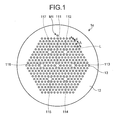
- FIG. 1 is a schematic cross-sectional view of a multi-core holey fiber (multi-core HF) according to a first embodiment of the present invention.
- a multi-core HF 1a includes core portions 111 to 117 arranged separated from each other and a cladding portion 12 positioned around the core portions 111 to 117.
- the core portions 111 to 117 and the cladding portion 12 are made of silica-based glass such as pure silica glass not containing any dopant for adjusting the refractive index.
- the core portion 111 is arranged at an approximate center portion of the cladding portion 12, and the core portions 112 to 117 are arranged at respective apexes of an equilateral hexagon around the core portion 111.
- the cladding portion 12 includes a plurality of holes 13 periodically arranged around the core portions 111 to 117.
- the holes 13 are arranged so as to form a triangular lattice L, and form equilateral hexagonal layers so as to surround each of the core portions 112 to 117.
- the core portions 111 to 117 are surrounded by the holes 13 of at least five-layers, and four holes 13 are each present between the core portions 111 to 117.
- the cladding portion 12 includes a marker M1 being a hole formed outside an area in which the holes 13 are formed and on an outer side of the core portion 112 and the core portion 117.
- the marker M1 is located at a position at approximately equal distances from the core portion 112 and the core portion 117.
- the multi-core HF 1a is configured to confine light to each of the core portions 111 to 117 by the holes 13 to propagate the light.
- a diameter d [ ⁇ m] of the holes 13 and a lattice constant ⁇ [ ⁇ m] of the triangular lattice L are not particularly limited and, thus, are set appropriately according to desired optical characteristics. For example, if d/ ⁇ is 0.35 to 0.65 and ⁇ is 10 ⁇ m, then similarly to the HF disclosed in Patent document 2, ESM characteristics are realized for each of the core portions 111 to 117 at least at a wavelength of 1260 nm to 1610 nm.
- an effective core area Aeff becomes large at approximately 114.6 ⁇ m 2
- a bending loss upon bending with a diameter of 20 mm becomes small at approximately 1.6 dB/m, and thus, an optical fiber with reduced optical nonlinearity and suitable for cabling is realized.
- the core portions are symmetrically arranged with respect to a central axis thereof, it is difficult to identify a specific core portion by the appearance.
- the cladding portion 12 of the multi-core HF 1a has the marker M1, a specific core portion is easily identified on the basis of the location of the marker M1.
- the marker M1 is a hole, the diameter thereof is not particularly limited, and the diameter may be, for example, approximately 1.0 ⁇ m to 10.0 ⁇ m.
- the marker M1 does not affect confinement of the light to the core portions 111 to 117 by the holes 13, and thus the optical characteristics of the multi-core HF 1a is not changed.
- the cladding portion 12 of the multi-core HF 1a includes the marker M1
- identification of a specific core portion of the core portions 111 to 117 becomes easy, and thus connection to another multi-core optical fiber becomes easy.
- the multi-core HFs 1a are to be connected to each other using fusion splicing, connector connection, or mechanical splice connection
- the following method for example, is used. Specifically, in a state in which end faces of, for example, two multi-core HFs 1a are placed opposite to each other, a mirror or a prism is inserted between the end faces of the two multi-core HFs 1a.
- At least one of the two multi-core HFs 1a is rotated around the central axis while the end faces of the two multi-core HFs 1a which have become observable from the outside by the mirror or the prism are being observed, and on the basis of the positions of the markers M1, a rotational position is determined so that, for example, the core portions 112 are connected to each other. Thereafter, the two multi-core HFs 1a are connected to each other.
- connection method light may be passed through a specific core portion, for example, a core portion 112 of one of the multi-core HFs 1a, and a light receiver may be connected to a core portion 112 at an end face on an opposite side of a to-be-connected-to end face of the other multi-core HG 1a, and then connection may be performed while intensity of the light received by the light receiver is being monitored.
- a specific core portion for example, a core portion 112 of one of the multi-core HFs 1a
- a light receiver may be connected to a core portion 112 at an end face on an opposite side of a to-be-connected-to end face of the other multi-core HG 1a, and then connection may be performed while intensity of the light received by the light receiver is being monitored.
- FIG. 2 is a schematic cross-sectional view of a multi-core HF 1b according to the first modification.
- the multi-core HF 1b has a configuration in which the marker M1 of the multi-core HF 1a illustrated in FIG. 1 is replaced with a marker M2.
- the marker M2 is a hole similar to the marker M1, but is located closer to the core portion 112 than to the core portion 117.
- the marker M2 is disposed so that its position changes from one cross section to a cross section opposite thereto and being its mirror image.
- the direction from the core portion 117 toward the core portion 112 is identifiable by the marker M2, and thus positions of the core portion 112 and the core portion 117 become more infallibly identifiable and positions of the other core portions also become more infallibly identifiable, facilitating the connection further.
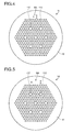
- FIG. 4 is a schematic cross-sectional view of a multi-core HF 1c according to a second modification.
- the multi-core HF 1c has a configuration in which the marker M1 of the multi-core HF 1a illustrated in FIG. 1 is replaced with a marker M3.
- the marker M3 has three holes formed into a triangle, and is formed so as to specify a direction from the core portion 117 to the core portion 112. Therefore, in the multi-core HF 1c, similarly to the marker M2 of the multi-core HF 1b, a specific direction around the periphery of the cladding portion 12 becomes identifiable and the position of each core portion becomes more infallibly identifiable by the marker M3, facilitating the connection further.
- FIG. 5 is a schematic cross-sectional view of a multi-core HF 1d according to a third modification.
- the multi-core HF 1d has a configuration in which the marker M1 of the multi-core HF 1a illustrated in FIG. 1 is replaced with a marker M4.
- the marker M4 also has three holes formed into a triangle so as to specify a direction from the core portion 117 to the core portion 112, but this triangle is elongated than that of the marker M3. Therefore, in the multi-core HF 1d, the position of each core portion is more infallibly identifiable by the marker M4, and the connection is facilitated even further.
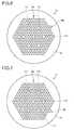
- FIG. 6 is a schematic cross-sectional view of a multi-core HF 1e according to a fourth modification.
- the multi-core HF 1e has a configuration in which the marker M1 of the multi-core HF 1a illustrated in FIG. 1 is replaced with markers M5 and M6, which are holes.
- the marker M5 is located, similarly to the marker M1, at a position that is approximately equally distant from the core portion 112 and the core portion 117, while the marker M6 is located on the outer side of the core portion 112 and the core portion 113.
- the markers M5 and M6 are arranged to face different sides of an equilateral-hexagonal area in which the holes 13 are formed, and thus the position of each core portion is more infallibly identifiable, and the connection is facilitated even further.
- FIG. 7 is a schematic cross-sectional view of a multi-core HF 1f according to a fifth modification.
- the multi-core HF 1f has a configuration in which the marker M6 of the multi-core HF 1e illustrated in FIG. 6 is replaced with a marker M7, which is holes.
- the marker M7 is located on the outer side of the core portion 113 and the core portion 114.
- the markers M5 and M7 are arranged to face different sides of an equilateral-hexagonal area in which the holes 13 are formed, and thus the position of each core portion is more infallibly identifiable, and the connection is facilitated even further.
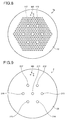
- FIG. 8 is a schematic cross-sectional view of a multi-core HF 1g according to a sixth modification.
- the multi-core HF 1g has a configuration in which the marker M3 of the multi-core HF 1c illustrated in FIG. 4 is replaced with a marker M8.
- the marker M8 is formed of three silica-based glass portions made of silica-based glass doped with a material having a refractive index different from that of the cladding portion 12, for example, doped with germanium, which increases the refractive index, or fluorine, which decreases the refractive index, and is formed into an approximate isosceles triangle so as to specify a direction from the core portion 117 to the core portion 112.
- the marker M8 a specific direction around the periphery of the cladding portion 12 is identifiable, the position of each core portion is more infallibly identifiable, and the connection is facilitated even further.
- an end face of an optical fiber is irradiated with light from a lateral side, the light transmitted through the optical fiber is imaged, and a position of a core portion is identified based on shading produced by a refractive-index difference between the core portion and the cladding portion on the picked-up image.
- a position of the marker M8 is identified based on shading produced by a refractive-index difference between the marker M8 and the cladding portion 12 on an image imaged by irradiating light from a lateral side, and the position of each core portion is identifiable based on the identified position.
- the multi-core HFs 1a to 1g may be manufactured using a well-known drill method, sol-gel method, or stack-and-draw method.
- the stack-and-draw method the following is performed.
- a pure silica-based glass tube solid pure silica-based glass rods to become core portions are placed, hollow pure silica-based glass capillaries to form holes are placed around the glass rods, and solid pure silica-based glass rods are filled into space between the glass tube and the glass capillaries, to produce a glass preform.
- one or more of the glass rods to be filled therein which corresponds/correspond to a position where a marker is to be formed is/are replaced with a hollow pure silica-based glass capillary/capillaries, or with a silica-based glass rod/rods doped with germanium, fluorine, or the like.
- the multi-core HFs 1a to 1g is able to be manufactured.
- a multi-core optical fiber according to the second embodiment is of a type having a refractive-index difference between core portions and a cladding portion and light is confined to the core portions by this refractive-index difference.
- FIG. 9 is a schematic cross-sectional view of a multi-core optical fiber according to the second embodiment.
- a multi-core optical fiber 2 includes core portions 211 to 217 which are disposed separated from each other and a cladding portion 22 around the core portions 211 to 217.
- the core portion 211 is arranged at an approximate center portion of the cladding portion 22, and the core portions 212 to 217 are arranged at respective apexes of an equilateral hexagon around the core portion 211.
- Each separated distance between the core portions 212 to 217 and the core diameters of the core portions 211 to 217 are not particularly limited.
- Each separated distance may be, for example, approximately 60 ⁇ m and the core diameter may be about 5.0 ⁇ m to 10.0 ⁇ m.
- Each of the core portions 211 to 217 is made of silica-based glass doped with germanium, and the cladding portion 12 is made of pure silica glass.
- the cladding portion 22 has a refractive index lower than a refractive index of each of the core portions 211 to 217, and a relative refractive-index difference of each of the core portions 211 to 217 with respect to the cladding portion 22 is approximately 0.3% to 1.5%.
- the multi-core optical fiber 2 confines the light to each of the core portions 211 to 217 by this refractive-index difference to propagate the light.
- the cladding portion 22 includes a marker M9 formed on an outer side of the core portion 212 and the core portion 217.
- the marker M9 has three holes formed into an approximate isosceles triangle, similarly to the marker M3 in the multi-core HF 1c, so as to specify a direction from the core portion 217 to the core portion 212.
- the marker M9 a specific direction around the periphery of the cladding portion 22 is identifiable and the position of each of the core portions 212 to 217 is more infallibly identifiable, facilitating the connection even further.
- This multi-core optical fiber 2 similarly to the multi-core HFs 1a to 1g, may be manufactured using a well-known drill method, sol-gel method, or stack-and-draw method.
- the stack-and-draw method in the manufacturing method, the pure silica-based glass capillaries are replaced with solid glass rods, and the glass rods to become core portions are made of silica-based glass doped with germanium of a predetermined amount.
- the multi-core HFs 1a to 1f include the markers M1 to M7, which are holes, in addition to the holes 13 for confining the light to the core portions 111 to 117, but part of the holes 13 may serve also as the marker.
- the hole 13 to be the marker shall be a hole separated from the core portions 111 to 117 as much as possible so as not to affect confinement of the light to the core portions 111 to 117, and a radius of this hole or a disposed position of the hole may be changed so that the hole is identifiable from the other holes 13.
- the markers which are holes, may be replaced with a marker made of a material having a refractive index different from that of the cladding portions.
- each of the first or the second embodiments, or the modifications thereof is just an example, and thus, the number and arrangement of the core portions, the holes for confining the light to the core portions, and the markers are not particularly limited. Furthermore, the material of the multi-core optical fiber is not particularly limited. Hereinafter, further modifications and embodiments will be explained.
- FIG. 10 is a schematic cross-sectional view of a multi-core HF 1h according to a seventh modification.
- the multi-core HF 1h has a configuration in which the number of holes 13, in the multi-core HF 1a illustrated in FIG. 1 , between the core portion 111 and each of the core portions 112 to 117 is increased from 4 to 9 and the marker M1 is replaced with a marker M10.
- each separated distance between the core portions 111 to 117 is longer than that in the multi-core HF 1a or the like, and thus, degradation of crosstalk of optical signals transmitted through the core portions 111 to 117 is suppressed, and a specific direction around the periphery of the cladding portion 12 is identifiable by the marker M10, facilitating the connection further.
- FIG. 11 is a schematic cross-sectional view of a multi-core HF 3 according to a third embodiment of the present invention.
- the multi-core HF 3 includes two core portions 311 and 312 and a cladding portion 32 provided around the core portions 311 and 312.
- the core portions 311 and 312 and the cladding portion 32 are made of silica-based glass such as pure silica glass.
- the cladding portion 32 includes a plurality of holes 33 arranged around the core portions 311 and 312.
- the holes 33 are arranged, similarly to the holes 13 in the multi-core HF 1a or the like, to form a triangular lattice, and form an equilateral-hexagonal layer so as to surround each of the core portions 311 and 312.
- each of the core portions core portions 311 and 312 is surrounded by holes 33 of at least five layers.
- diameters of the holes 33 and a lattice constant of the triangular lattice are not particularly limited, they may be the same as those of, for example, the multi-core HF 1a.
- the cladding portion 32 includes a marker M11, which is a hole located outside an area in which the holes 33 are formed and at a position closer to the core portion 312 than to the core portion 311.
- a specific direction around the periphery of the cladding portion 32 is identifiable by the marker M11, and thus the connection is further facilitated.
- FIG. 12 is a schematic cross-sectional view of a multi-core HF 4 according to a fourth embodiment of the present invention.
- the multi-core HF 4 includes three core portions 411 to 413 and a cladding portion 42 around the core portions 411 to 413.
- the core portions 411 to 413 and the cladding portion 42 are made of silica-based glass such as pure silica glass.
- the cladding portion 42 includes a plurality of holes 43, similar to the holes 13 in the multi-core HF 1a or the like, which are arranged to form a triangular lattice around the core portions 411 to 413. Furthermore, the cladding portion 42 includes markers M12 and M13 arranged to face different sides of a polygonal area in which the holes 43 are formed. In the multi-core HF 4 also, a specific direction around the periphery of the cladding portion 42 is identifiable by the markers M12 and 13, and thus the connection is further facilitated.
- FIG. 13 is a schematic cross-sectional view of a multi-core HF 5 according to a fifth embodiment of the present invention.
- the multi-core HF 5 includes four core portions 511 to 514 and a cladding portion 52 positioned around core portions 511 to 514.
- the core portions 511 to 514 and the cladding portion 52 are made of silica-based glass such as pure silica glass.
- the cladding portion 52 includes a plurality of holes 53, similar to the holes 13 in the multi-core HF 1a or the like, which are arranged to form a triangular lattice around the core portions 511 to 514. Furthermore, the cladding portion 52 includes a marker M14 having three holes formed into a triangle, which is arranged outside an area in which the holes 53 are formed and on an outer side of the core portion 511. In the multi-core HF 5 also, a specific direction around the periphery of the cladding portion 52 is identifiable by the marker M14, and thus the connection is further facilitated.
- the present invention may be applied to a multi-core optical fiber configured as illustrated in FIG. 9 , in which core portions are arranged similarly to the multi-core HFs illustrated in FIGS. 11 to 13 , to arrange a marker as appropriate.
- multi-core optical fibers were manufactured, which confine light to core portions by a refractive-index difference between the core portions and a cladding portion, by using the stack-and-draw method, similarly to the multi-core optical fiber according to the second embodiment.
- a pure silica-based glass tube core portions having a diameter of 7 mm and which have been doped with germanium so that a relative refractive-index difference with respect to pure silica becomes 0.3%, and solid silica-based glass rods forming a cladding portion about four times each core portion around the core portions, are placed in an equilateral hexagonal shape and at the center of this equilateral hexagon, and a space between the glass tube and the glass capillaries is filled with a large number of solid pure silica-based glass rods, to produce a glass preform.
- the diameter of the glass preform (that is, the diameter of the pure silica-based glass tube) was 24 mm in the first example and 36 mm in the second example.
- glass rods at positions where markers were to be formed were replaced with hollow pure silica-based glass capillaries.
- the positions where the markers were to be formed similarly to the multi-core optical fiber according to the fifth modification illustrated in Fig. 7 , faced two different sides of the equilateral hexagon formed by the core portions, and one or two holes were arranged at each position. Thereafter, the glass preform was drawn to manufacture the multi-core optical fibers according to the first and the second examples.
- FIG. 14 is a cross-sectional photograph of the multi-core optical fiber according to the first example.
- FIG. 15 is a cross-sectional photograph of the multi-core optical fiber according to the second example.
- circular areas surrounded by dotted lines represent positions of the core portions. Solid circles represent the markers.
- the core diameter is approximately 10 ⁇ m, and a separated distance between the cores is approximately 40 ⁇ m.
- An outer diameter of the multi-core optical fiber is 141 ⁇ m in the first example, and 215 ⁇ m in the second example.
- the multi-core optical fibers according to the first and the second examples a specific direction around the periphery of the cladding portion is identifiable and the position of each core portion is more infallibly identifiable, further facilitating the connection. Moreover, like the multi-core optical fibers according to the first and the second examples, even if the number of cores, the diameter of the cores, and the separated distance between the cores are the same, by changing the diameter of the glass tube, multi-core optical fibers of different diameters are easily obtainable.
- the multi-core optical fiber according to the present invention is suitable for use in, for example, optical communications.
Landscapes
- Physics & Mathematics (AREA)
- General Physics & Mathematics (AREA)
- Optics & Photonics (AREA)
- Optical Fibers, Optical Fiber Cores, And Optical Fiber Bundles (AREA)
- Optical Couplings Of Light Guides (AREA)
Abstract
Description
- The present invention relates to a multi-core optical fiber having a plurality of core portions.
- As means for remarkably increasing communication capacity, multi-core optical fibers, each having a plurality of core portions, have been disclosed.
- As one type of the multi-core optical fibers, a multi-core holey fiber is disclosed (see Patent Document 1). This holey fiber is an optical fiber that has core portions and a cladding portion positioned around the core portions and having a plurality of holes arranged around the core portions. In the holey fiber, an average refractive index of the cladding portion is reduced by the holes, and the principle of total reflection of light is utilized to confine the light to the core portions and to propagate the light (see Patent Document 2). Because the refractive index is controlled by the holes, the holey fiber is able to realize endlessly single mode (ESM) characteristics realizing single mode transmission at all wavelengths and unique properties such as anomalous dispersion at shorter wavelengths. A multi-core holey fiber is a holey fiber having a plurality of core portions, and is thought of as being possible to realize SDM transmission in addition to the ESM characteristics.
-
- Patent Document 1: Japanese National Publication of International Patent Application No.
2008-534995 - Patent Document 2: International Publication Pamphlet No.
WO2008/093870 - When the multi-core optical fiber is connected to another multi-core optical fiber or to an optical device by fusion splicing or the like, it is necessary to connect a specific core portion of the multi-core optical fiber and a specific core portion of the another multi-core optical fiber or the optical device.
- However, if the plurality of core portions is symmetrically arranged with respect to a central axis in the multi-core optical fiber, there is a problem that it is difficult to identify the specific core portion by the appearance.
- The present invention has been achieved in view of the above, and an object of the present invention is to provide a multi-core optical fiber that is easily connected.
- In order to solve the above described problems and achieve the object, a multi-core optical fiber according to the present invention includes: a plurality of core portions; and a cladding portion positioned around the plurality of core portions, wherein the cladding portion has a marker for identifying a position of a specific core portion of the plurality of core portions.
- Further, in the multi-core optical fiber according to the present invention, the marker is formed so that a specific direction around a periphery of the cladding portion is identifiable.
- Further, in the multi-core optical fiber according to the present invention, the cladding portion includes a plurality of holes that are arranged around the plurality of core portions and that are configured to confine light to each of the plurality of core portions.
- Further, in the multi-core optical fiber according to the present invention, the cladding portion has a refractive index lower than a refractive index of each of the plurality of core portions, and light is confined to each of the plurality of core portions by a refractive-index difference between the cladding portion and each of the plurality of core portions.
- Further, in the multi-core optical fiber according to the present invention, the marker is a hole formed in the cladding portion.
- Further, in the multi-core optical fiber according to the present invention, the marker is made of a material having a refractive index different from that of the cladding portion.
- Further, in the multi-core optical fiber according to the present invention, the marker is a hole formed in the cladding portion and serves also as a hole for confining the light to each of the plurality of core portions.
- According to the present invention, it is possible to easily identify a position of a specific core portion, and thus there is an effect that it is possible to realize a multi-core optical fiber that is easily connected.
-
-
FIG. 1 is a schematic cross-sectional view of a multi-core HF according to a first embodiment. -
FIG. 2 is a schematic cross-sectional view of a multi-core HF according to a first modification. -
FIG. 3 is a cross-sectional view of a cross section opposed to the cross section illustrated inFIG. 2 when the multi-core HF illustrated inFIG. 2 is cut. -
FIG. 4 is a schematic cross-sectional view of a multi-core HF according to a second modification. -
FIG. 5 is a schematic cross-sectional view of a multi-core HF according to a third modification. -
FIG. 6 is a schematic cross-sectional view of a multi-core HF according to a fourth modification. -
FIG. 7 is a schematic cross-sectional view of a multi-core HF according to a fifth modification. -
FIG. 8 is a schematic cross-sectional view of a multi-core HF according to a sixth modification. -
FIG. 9 is a schematic cross-sectional view of a multi-core optical fiber according to a second embodiment. -
FIG. 10 is a schematic cross-sectional view of a multi-core HF according to a seventh modification. -
FIG. 11 is a schematic cross-sectional view of a multi-core optical fiber according to a third embodiment. -
FIG. 12 is a schematic cross-sectional view of a multi-core optical fiber according to a fourth embodiment. -
FIG. 13 is a schematic cross-sectional view of a multi-core optical fiber according to a fifth embodiment. -
FIG. 14 is a cross-sectional photograph of a multi-core optical fiber according to a first example. -
FIG. 15 is a cross-sectional photograph of a multi-core optical fiber according to a second example. - Embodiments of a multi-core optical fiber according to the present invention will be explained in detail below with reference to the drawings. The present invention is not limited by the embodiments. In addition, those terms, which are not particularly defined in this specification, follow the definitions and measurement methods defined by ITU-T (International Telecommunication Union Telecommunication Standardization Sector) G.650.1.
-
FIG. 1 is a schematic cross-sectional view of a multi-core holey fiber (multi-core HF) according to a first embodiment of the present invention. As illustrated inFIG. 1 , amulti-core HF 1a includescore portions 111 to 117 arranged separated from each other and acladding portion 12 positioned around thecore portions 111 to 117. Thecore portions 111 to 117 and thecladding portion 12 are made of silica-based glass such as pure silica glass not containing any dopant for adjusting the refractive index. - The
core portion 111 is arranged at an approximate center portion of thecladding portion 12, and thecore portions 112 to 117 are arranged at respective apexes of an equilateral hexagon around thecore portion 111. Thecladding portion 12 includes a plurality ofholes 13 periodically arranged around thecore portions 111 to 117. Theholes 13 are arranged so as to form a triangular lattice L, and form equilateral hexagonal layers so as to surround each of thecore portions 112 to 117. Moreover, in themulti-core HF 1a, thecore portions 111 to 117 are surrounded by theholes 13 of at least five-layers, and fourholes 13 are each present between thecore portions 111 to 117. Thecladding portion 12 includes a marker M1 being a hole formed outside an area in which theholes 13 are formed and on an outer side of thecore portion 112 and thecore portion 117. The marker M1 is located at a position at approximately equal distances from thecore portion 112 and thecore portion 117. - The
multi-core HF 1a is configured to confine light to each of thecore portions 111 to 117 by theholes 13 to propagate the light. A diameter d [µm] of theholes 13 and a lattice constant Λ [µm] of the triangular lattice L are not particularly limited and, thus, are set appropriately according to desired optical characteristics. For example, if d/Λ is 0.35 to 0.65 and Λ is 10 µm, then similarly to the HF disclosed inPatent document 2, ESM characteristics are realized for each of thecore portions 111 to 117 at least at a wavelength of 1260 nm to 1610 nm. Furthermore, at a wavelength of 1550 nm, an effective core area Aeff becomes large at approximately 114.6 µm2, and a bending loss upon bending with a diameter of 20 mm becomes small at approximately 1.6 dB/m, and thus, an optical fiber with reduced optical nonlinearity and suitable for cabling is realized. - In the conventional multi-core HF, because the core portions are symmetrically arranged with respect to a central axis thereof, it is difficult to identify a specific core portion by the appearance. However, as explained above, because the
cladding portion 12 of themulti-core HF 1a has the marker M1, a specific core portion is easily identified on the basis of the location of the marker M1. The marker M1 is a hole, the diameter thereof is not particularly limited, and the diameter may be, for example, approximately 1.0 µm to 10.0 µm. Furthermore, if present outside the area in which theholes 13 are formed, like the marker M1, the marker M1 does not affect confinement of the light to thecore portions 111 to 117 by theholes 13, and thus the optical characteristics of themulti-core HF 1a is not changed. - As explained above, because the
cladding portion 12 of themulti-core HF 1a includes the marker M1, identification of a specific core portion of thecore portions 111 to 117 becomes easy, and thus connection to another multi-core optical fiber becomes easy. - If, for example, the
multi-core HFs 1a are to be connected to each other using fusion splicing, connector connection, or mechanical splice connection, the following method, for example, is used. Specifically, in a state in which end faces of, for example, twomulti-core HFs 1a are placed opposite to each other, a mirror or a prism is inserted between the end faces of the twomulti-core HFs 1a. Then, at least one of the twomulti-core HFs 1a is rotated around the central axis while the end faces of the twomulti-core HFs 1a which have become observable from the outside by the mirror or the prism are being observed, and on the basis of the positions of the markers M1, a rotational position is determined so that, for example, thecore portions 112 are connected to each other. Thereafter, the twomulti-core HFs 1a are connected to each other. - In the connection method, light may be passed through a specific core portion, for example, a
core portion 112 of one of themulti-core HFs 1a, and a light receiver may be connected to acore portion 112 at an end face on an opposite side of a to-be-connected-to end face of the othermulti-core HG 1a, and then connection may be performed while intensity of the light received by the light receiver is being monitored. In this case, by using the markers M1 for coarse adjustment of rotational positions of the twomulti-core HFs 1a, and performing fine adjustment of the rotational positions by a light intensity monitor, it is possible to achieve quick and easy coarse adjustment and accurate fine adjustment. - Next, first to sixth modifications of the
multi-core HF 1a according to the first embodiment will be explained below.FIG. 2 is a schematic cross-sectional view of amulti-core HF 1b according to the first modification. As illustrated inFIG. 2 , themulti-core HF 1b has a configuration in which the marker M1 of themulti-core HF 1a illustrated inFIG. 1 is replaced with a marker M2. The marker M2 is a hole similar to the marker M1, but is located closer to thecore portion 112 than to thecore portion 117. As a result, in themulti-core HF 1b, it is possible to identify a specific direction around a periphery of thecladding portion 12, for example, a direction from thecore portion 117 toward thecore portion 112 by the marker M2. - More specifically, if the
multi-core HF 1b is cut, one of the cross section is as illustrated inFIG. 2 , while the other cross section opposite thereto becomes, as illustrated inFIG. 3 , mirror-symmetrical with respect to the cross section inFIG. 2 , and thus the positions of thecore portion 112 and thecore portion 117 are interchanged. However, as illustrated inFIG. 3 , the marker M2 is disposed so that its position changes from one cross section to a cross section opposite thereto and being its mirror image. As a result, in themulti-core HF 1b, the direction from thecore portion 117 toward thecore portion 112 is identifiable by the marker M2, and thus positions of thecore portion 112 and thecore portion 117 become more infallibly identifiable and positions of the other core portions also become more infallibly identifiable, facilitating the connection further. -
FIG. 4 is a schematic cross-sectional view of amulti-core HF 1c according to a second modification. As illustrated inFIG. 4 , themulti-core HF 1c has a configuration in which the marker M1 of themulti-core HF 1a illustrated inFIG. 1 is replaced with a marker M3. The marker M3 has three holes formed into a triangle, and is formed so as to specify a direction from thecore portion 117 to thecore portion 112. Therefore, in themulti-core HF 1c, similarly to the marker M2 of themulti-core HF 1b, a specific direction around the periphery of thecladding portion 12 becomes identifiable and the position of each core portion becomes more infallibly identifiable by the marker M3, facilitating the connection further. -
FIG. 5 is a schematic cross-sectional view of amulti-core HF 1d according to a third modification. As illustrated inFIG. 5 , themulti-core HF 1d has a configuration in which the marker M1 of themulti-core HF 1a illustrated inFIG. 1 is replaced with a marker M4. Similarly to the marker M3 of themulti-core HF 1c, the marker M4 also has three holes formed into a triangle so as to specify a direction from thecore portion 117 to thecore portion 112, but this triangle is elongated than that of the marker M3. Therefore, in themulti-core HF 1d, the position of each core portion is more infallibly identifiable by the marker M4, and the connection is facilitated even further. -
FIG. 6 is a schematic cross-sectional view of amulti-core HF 1e according to a fourth modification. As illustrated inFIG. 6 , themulti-core HF 1e has a configuration in which the marker M1 of themulti-core HF 1a illustrated inFIG. 1 is replaced with markers M5 and M6, which are holes. The marker M5 is located, similarly to the marker M1, at a position that is approximately equally distant from thecore portion 112 and thecore portion 117, while the marker M6 is located on the outer side of thecore portion 112 and thecore portion 113. As explained above, in thismulti-core HF 1e, the markers M5 and M6 are arranged to face different sides of an equilateral-hexagonal area in which theholes 13 are formed, and thus the position of each core portion is more infallibly identifiable, and the connection is facilitated even further. -
FIG. 7 is a schematic cross-sectional view of amulti-core HF 1f according to a fifth modification. As illustrated inFIG. 7 , themulti-core HF 1f has a configuration in which the marker M6 of themulti-core HF 1e illustrated inFIG. 6 is replaced with a marker M7, which is holes. The marker M7 is located on the outer side of thecore portion 113 and thecore portion 114. In themulti-core HF 1f, similarly to themulti-core HF 1e, the markers M5 and M7 are arranged to face different sides of an equilateral-hexagonal area in which theholes 13 are formed, and thus the position of each core portion is more infallibly identifiable, and the connection is facilitated even further. -
FIG. 8 is a schematic cross-sectional view of amulti-core HF 1g according to a sixth modification. As illustrated inFIG. 8 , themulti-core HF 1g has a configuration in which the marker M3 of themulti-core HF 1c illustrated inFIG. 4 is replaced with a marker M8. The marker M8 is formed of three silica-based glass portions made of silica-based glass doped with a material having a refractive index different from that of thecladding portion 12, for example, doped with germanium, which increases the refractive index, or fluorine, which decreases the refractive index, and is formed into an approximate isosceles triangle so as to specify a direction from thecore portion 117 to thecore portion 112. As a result, in themulti-core HF 1g, by the marker M8, a specific direction around the periphery of thecladding portion 12 is identifiable, the position of each core portion is more infallibly identifiable, and the connection is facilitated even further. - When ordinary optical fibers are fusion spliced, an end face of an optical fiber is irradiated with light from a lateral side, the light transmitted through the optical fiber is imaged, and a position of a core portion is identified based on shading produced by a refractive-index difference between the core portion and the cladding portion on the picked-up image. In the
multi-core HF 1g also, similarly to the ordinary optical fibers, a position of the marker M8 is identified based on shading produced by a refractive-index difference between the marker M8 and thecladding portion 12 on an image imaged by irradiating light from a lateral side, and the position of each core portion is identifiable based on the identified position. - Next, a method of manufacturing
multi-core HFs 1a to 1g according to the first embodiment and the first to sixth modifications will be explained below. Themulti-core HFs 1a to 1g may be manufactured using a well-known drill method, sol-gel method, or stack-and-draw method. When the stack-and-draw method is used, the following is performed. In, for example, a pure silica-based glass tube, solid pure silica-based glass rods to become core portions are placed, hollow pure silica-based glass capillaries to form holes are placed around the glass rods, and solid pure silica-based glass rods are filled into space between the glass tube and the glass capillaries, to produce a glass preform. When this is performed, one or more of the glass rods to be filled therein, which corresponds/correspond to a position where a marker is to be formed is/are replaced with a hollow pure silica-based glass capillary/capillaries, or with a silica-based glass rod/rods doped with germanium, fluorine, or the like. Thereafter, by drawing the glass preform, themulti-core HFs 1a to 1g is able to be manufactured. - Next, a second embodiment of the present invention will be explained below. A multi-core optical fiber according to the second embodiment is of a type having a refractive-index difference between core portions and a cladding portion and light is confined to the core portions by this refractive-index difference.
-
FIG. 9 is a schematic cross-sectional view of a multi-core optical fiber according to the second embodiment. As illustrated inFIG. 9 , a multi-coreoptical fiber 2 includescore portions 211 to 217 which are disposed separated from each other and acladding portion 22 around thecore portions 211 to 217. Thecore portion 211 is arranged at an approximate center portion of thecladding portion 22, and thecore portions 212 to 217 are arranged at respective apexes of an equilateral hexagon around thecore portion 211. Each separated distance between thecore portions 212 to 217 and the core diameters of thecore portions 211 to 217 are not particularly limited. Each separated distance may be, for example, approximately 60 µm and the core diameter may be about 5.0 µm to 10.0 µm. Each of thecore portions 211 to 217 is made of silica-based glass doped with germanium, and thecladding portion 12 is made of pure silica glass. As a result, thecladding portion 22 has a refractive index lower than a refractive index of each of thecore portions 211 to 217, and a relative refractive-index difference of each of thecore portions 211 to 217 with respect to thecladding portion 22 is approximately 0.3% to 1.5%. The multi-coreoptical fiber 2 confines the light to each of thecore portions 211 to 217 by this refractive-index difference to propagate the light. - Moreover, in the multi-core
optical fiber 2, thecladding portion 22 includes a marker M9 formed on an outer side of thecore portion 212 and thecore portion 217. The marker M9 has three holes formed into an approximate isosceles triangle, similarly to the marker M3 in themulti-core HF 1c, so as to specify a direction from thecore portion 217 to thecore portion 212. As a result, also in the multi-coreoptical fiber 2, by the marker M9, a specific direction around the periphery of thecladding portion 22 is identifiable and the position of each of thecore portions 212 to 217 is more infallibly identifiable, facilitating the connection even further. - This multi-core
optical fiber 2, similarly to themulti-core HFs 1a to 1g, may be manufactured using a well-known drill method, sol-gel method, or stack-and-draw method. When the stack-and-draw method is used, in the manufacturing method, the pure silica-based glass capillaries are replaced with solid glass rods, and the glass rods to become core portions are made of silica-based glass doped with germanium of a predetermined amount. - The
multi-core HFs 1a to 1f according to the first embodiment or the modifications thereof include the markers M1 to M7, which are holes, in addition to theholes 13 for confining the light to thecore portions 111 to 117, but part of theholes 13 may serve also as the marker. In this case, thehole 13 to be the marker shall be a hole separated from thecore portions 111 to 117 as much as possible so as not to affect confinement of the light to thecore portions 111 to 117, and a radius of this hole or a disposed position of the hole may be changed so that the hole is identifiable from the other holes 13. - In the
multi-core HFs 1a to 1f according to the first embodiment or the modifications thereof, or in the multi-coreoptical fiber 2 according to the second embodiment, the markers, which are holes, may be replaced with a marker made of a material having a refractive index different from that of the cladding portions. - Each of the first or the second embodiments, or the modifications thereof is just an example, and thus, the number and arrangement of the core portions, the holes for confining the light to the core portions, and the markers are not particularly limited. Furthermore, the material of the multi-core optical fiber is not particularly limited. Hereinafter, further modifications and embodiments will be explained.
-
FIG. 10 is a schematic cross-sectional view of amulti-core HF 1h according to a seventh modification. As illustrated inFIG. 10 , themulti-core HF 1h has a configuration in which the number ofholes 13, in themulti-core HF 1a illustrated inFIG. 1 , between thecore portion 111 and each of thecore portions 112 to 117 is increased from 4 to 9 and the marker M1 is replaced with a marker M10. In themulti-core HF 1h, each separated distance between thecore portions 111 to 117 is longer than that in themulti-core HF 1a or the like, and thus, degradation of crosstalk of optical signals transmitted through thecore portions 111 to 117 is suppressed, and a specific direction around the periphery of thecladding portion 12 is identifiable by the marker M10, facilitating the connection further. -
FIG. 11 is a schematic cross-sectional view of amulti-core HF 3 according to a third embodiment of the present invention. As illustrated inFIG. 11 , themulti-core HF 3 includes twocore portions cladding portion 32 provided around thecore portions core portions cladding portion 32 are made of silica-based glass such as pure silica glass. - The
cladding portion 32 includes a plurality ofholes 33 arranged around thecore portions holes 33 are arranged, similarly to theholes 13 in themulti-core HF 1a or the like, to form a triangular lattice, and form an equilateral-hexagonal layer so as to surround each of thecore portions portions core portions holes 33 of at least five layers. Although diameters of theholes 33 and a lattice constant of the triangular lattice are not particularly limited, they may be the same as those of, for example, themulti-core HF 1a. Furthermore, thecladding portion 32 includes a marker M11, which is a hole located outside an area in which theholes 33 are formed and at a position closer to thecore portion 312 than to thecore portion 311. In themulti-core HF 3 also, a specific direction around the periphery of thecladding portion 32 is identifiable by the marker M11, and thus the connection is further facilitated. -
FIG. 12 is a schematic cross-sectional view of a multi-core HF 4 according to a fourth embodiment of the present invention. As illustrated inFIG. 12 , the multi-core HF 4 includes threecore portions 411 to 413 and acladding portion 42 around thecore portions 411 to 413. Thecore portions 411 to 413 and thecladding portion 42 are made of silica-based glass such as pure silica glass. - The
cladding portion 42 includes a plurality ofholes 43, similar to theholes 13 in themulti-core HF 1a or the like, which are arranged to form a triangular lattice around thecore portions 411 to 413. Furthermore, thecladding portion 42 includes markers M12 and M13 arranged to face different sides of a polygonal area in which theholes 43 are formed. In the multi-core HF 4 also, a specific direction around the periphery of thecladding portion 42 is identifiable by the markers M12 and 13, and thus the connection is further facilitated. -
FIG. 13 is a schematic cross-sectional view of a multi-core HF 5 according to a fifth embodiment of the present invention. As illustrated inFIG. 13 , the multi-core HF 5 includes fourcore portions 511 to 514 and acladding portion 52 positioned aroundcore portions 511 to 514. Thecore portions 511 to 514 and thecladding portion 52 are made of silica-based glass such as pure silica glass. - The
cladding portion 52 includes a plurality ofholes 53, similar to theholes 13 in themulti-core HF 1a or the like, which are arranged to form a triangular lattice around thecore portions 511 to 514. Furthermore, thecladding portion 52 includes a marker M14 having three holes formed into a triangle, which is arranged outside an area in which theholes 53 are formed and on an outer side of thecore portion 511. In the multi-core HF 5 also, a specific direction around the periphery of thecladding portion 52 is identifiable by the marker M14, and thus the connection is further facilitated. - The present invention may be applied to a multi-core optical fiber configured as illustrated in
FIG. 9 , in which core portions are arranged similarly to the multi-core HFs illustrated inFIGS. 11 to 13 , to arrange a marker as appropriate. - As first and second examples of the present invention, multi-core optical fibers were manufactured, which confine light to core portions by a refractive-index difference between the core portions and a cladding portion, by using the stack-and-draw method, similarly to the multi-core optical fiber according to the second embodiment.
- Specifically, first, in a pure silica-based glass tube, core portions having a diameter of 7 mm and which have been doped with germanium so that a relative refractive-index difference with respect to pure silica becomes 0.3%, and solid silica-based glass rods forming a cladding portion about four times each core portion around the core portions, are placed in an equilateral hexagonal shape and at the center of this equilateral hexagon, and a space between the glass tube and the glass capillaries is filled with a large number of solid pure silica-based glass rods, to produce a glass preform. The diameter of the glass preform (that is, the diameter of the pure silica-based glass tube) was 24 mm in the first example and 36 mm in the second example.
- When the glass rods were filled in, glass rods at positions where markers were to be formed were replaced with hollow pure silica-based glass capillaries. The positions where the markers were to be formed, similarly to the multi-core optical fiber according to the fifth modification illustrated in
Fig. 7 , faced two different sides of the equilateral hexagon formed by the core portions, and one or two holes were arranged at each position. Thereafter, the glass preform was drawn to manufacture the multi-core optical fibers according to the first and the second examples. -
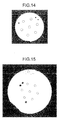
FIG. 14 is a cross-sectional photograph of the multi-core optical fiber according to the first example.FIG. 15 is a cross-sectional photograph of the multi-core optical fiber according to the second example. InFIGS. 14 and 15 , circular areas surrounded by dotted lines represent positions of the core portions. Solid circles represent the markers. Furthermore, in both the first and the second examples, the core diameter is approximately 10 µm, and a separated distance between the cores is approximately 40 µm. An outer diameter of the multi-core optical fiber is 141 µm in the first example, and 215 µm in the second example. - As illustrated in
FIGS. 14 and 15 , in the multi-core optical fibers according to the first and the second examples, a specific direction around the periphery of the cladding portion is identifiable and the position of each core portion is more infallibly identifiable, further facilitating the connection. Moreover, like the multi-core optical fibers according to the first and the second examples, even if the number of cores, the diameter of the cores, and the separated distance between the cores are the same, by changing the diameter of the glass tube, multi-core optical fibers of different diameters are easily obtainable. - The multi-core optical fiber according to the present invention is suitable for use in, for example, optical communications.
-
- 1a to 1h, 3 to 5 Multi-core HF
- 111 to 117, 211 to 217, 311, 312, 411 to 413, 511 to 514 Core portion
- 12 to 52 Cladding portion
- 13, 33 to 53 Hole
- 2 Multi-core optical fiber
- L Triangular lattice
- M1 to M14 Marker
Claims (7)
- A multi-core optical fiber, comprising:a plurality of core portions; anda cladding portion positioned around the plurality of core portions, whereinthe cladding portion has a marker for identifying a position of a specific core portion of the plurality of core portions.
- The multi-core optical fiber according to claim 1, wherein the marker is formed so that a specific direction around a periphery of the cladding portion is identifiable.
- The multi-core optical fiber according to claim 1 or 2, wherein the cladding portion comprises a plurality of holes that are arranged around the plurality of core portions and that are configured to confine light to each of the plurality of core portions.
- The multi-core optical fiber according to claim 1 or 2, wherein
the cladding portion has a refractive index lower than a refractive index of each of the plurality of core portions, and
light is confined to each of the plurality of core portions by a refractive-index difference between the cladding portion and each of the plurality of core portions. - The multi-core optical fiber according to any one of claims 1 to 4, wherein the marker is a hole formed in the cladding portion.
- The multi-core optical fiber according to any one of claims 1 to 4, wherein the marker is made of a material having a refractive index different from that of the cladding portion.
- The multi-core optical fiber according to claim 3, wherein the marker is a hole formed in the cladding portion and serves also as a hole for confining the light to each of the plurality of core portions.
Applications Claiming Priority (2)
| Application Number | Priority Date | Filing Date | Title |
|---|---|---|---|
| JP2008327924 | 2008-12-24 | ||
| PCT/JP2009/068908 WO2010073821A1 (en) | 2008-12-24 | 2009-11-05 | Multi-core optical fiber |
Publications (2)
| Publication Number | Publication Date |
|---|---|
| EP2369380A1 true EP2369380A1 (en) | 2011-09-28 |
| EP2369380A4 EP2369380A4 (en) | 2014-04-16 |
Family
ID=42287446
Family Applications (1)
| Application Number | Title | Priority Date | Filing Date |
|---|---|---|---|
| EP09834625.7A Withdrawn EP2369380A4 (en) | 2008-12-24 | 2009-11-05 | OPTICAL FIBER AT MULTIPLE |
Country Status (5)
| Country | Link |
|---|---|
| US (2) | US8041173B2 (en) |
| EP (1) | EP2369380A4 (en) |
| JP (1) | JP5367726B2 (en) |
| CN (1) | CN102257415B (en) |
| WO (1) | WO2010073821A1 (en) |
Cited By (1)
| Publication number | Priority date | Publication date | Assignee | Title |
|---|---|---|---|---|
| EP2538251A4 (en) * | 2010-02-18 | 2017-11-08 | Sumitomo Electric Industries, Ltd. | Multi-core optical fibre |
Families Citing this family (31)
| Publication number | Priority date | Publication date | Assignee | Title |
|---|---|---|---|---|
| JP5415728B2 (en) * | 2008-08-29 | 2014-02-12 | 古河電気工業株式会社 | Multi-core holey fiber and optical transmission system |
| WO2010119930A1 (en) * | 2009-04-16 | 2010-10-21 | 古河電気工業株式会社 | Multi-core optical fiber |
| US8737793B2 (en) | 2010-03-16 | 2014-05-27 | Furukawa Electric Co., Ltd. | Multi-core optical fiber and method of manufacturing the same |
| CN103403591A (en) * | 2011-03-04 | 2013-11-20 | 株式会社藤仓 | Multi-core fiber, and multi-core fiber connection method using the same |
| JP2013020075A (en) * | 2011-07-11 | 2013-01-31 | Hitachi Cable Ltd | Method for manufacturing multi-core fiber |
| JP2013020074A (en) * | 2011-07-11 | 2013-01-31 | Hitachi Cable Ltd | Multi-core fiber |
| JP6082523B2 (en) | 2011-08-01 | 2017-02-15 | 古河電気工業株式会社 | Multi-core fiber connection method, multi-core fiber, and multi-core fiber manufacturing method |
| JP2015004695A (en) * | 2011-10-21 | 2015-01-08 | コニカミノルタ株式会社 | Coupling method |
| DE102012106806B4 (en) * | 2012-07-26 | 2022-07-28 | J-Fiber Gmbh | Sensor fiber for temperature, strain and/or torsion detection in the form of a multi-core optical waveguide with a fiber Bragg grating structure |
| CN102819062B (en) * | 2012-07-31 | 2014-06-11 | 燕山大学 | Air hole square array fiber core annular doping four-core photonic crystal fiber |
| US9372304B2 (en) * | 2013-03-28 | 2016-06-21 | Ofs Fitel, Llc | Apparatus for alignment of a multicore fiber in a multifiber connector and method of using same |
| CN104238004A (en) * | 2013-06-18 | 2014-12-24 | 深圳市中技源专利城有限公司 | Multi-core plastic optical fibers and plastic optical fiber cable |
| JP5808790B2 (en) | 2013-11-22 | 2015-11-10 | 株式会社フジクラ | Multi-core fiber |
| CN103698840B (en) * | 2013-11-26 | 2016-09-14 | 长飞光纤光缆股份有限公司 | A kind of multi-core nonlinear optical fiber |
| PL227732B1 (en) * | 2013-12-04 | 2018-01-31 | Fund Polskie Centrum Fotoniki I Swiatlowodow | Microstructural optical fiber with selectively enlarged spaces with a reduced refractive index, especially for the generation of non-linear effects and stress measurement |
| PL226046B1 (en) * | 2013-12-15 | 2017-06-30 | Inphotech Spółka Z Ograniczoną Odpowiedzialnością | Microstructural multicore optical fiber, device for independent addressing of the cores of a multicore microstructured optical fiber and the implementation of a device for the independent addressing of the cores of a multicore microstructured fiber |
| JP6287179B2 (en) * | 2013-12-25 | 2018-03-07 | 住友電気工業株式会社 | Multi-core optical fiber and method for manufacturing multi-core optical fiber connector |
| EP3234665B1 (en) * | 2014-12-18 | 2024-08-21 | NKT Photonics A/S | A photonic crystal fiber, a method of production thereof and a supercontinuum light source |
| CN104898199B (en) * | 2015-06-26 | 2018-07-17 | 深圳市通盛新材料有限公司 | A kind of connection structure of multicore photonic crystal optical fiber and laser light source |
| WO2020195739A1 (en) | 2019-03-27 | 2020-10-01 | 古河電気工業株式会社 | Multicore fiber preform manufacturing method, multicore fiber preform, and multicore fiber |
| JP7389644B2 (en) * | 2019-12-26 | 2023-11-30 | 株式会社フジクラ | Multicore fibers, fiber optic cables, and optical connectors |
| EP4162308A1 (en) | 2020-06-03 | 2023-04-12 | Intuitive Surgical Operations, Inc. | Directing light into an optical fiber |
| JP7405259B2 (en) * | 2020-07-06 | 2023-12-26 | 日本電信電話株式会社 | Optical fiber and its connection method |
| US12032200B2 (en) * | 2021-12-28 | 2024-07-09 | Sterlite Technologies Limited | Trench assisted multi-core optical fiber with reduced crosstalk |
| US20250340477A1 (en) * | 2022-01-14 | 2025-11-06 | Heraeus Quartz North America Llc | Reduction of multi-core fiber preform geometric distortion |
| US20250216595A1 (en) * | 2022-03-24 | 2025-07-03 | Sumitomo Electric Industries, Ltd. | Multicore optical fiber |
| US20250076569A1 (en) * | 2022-03-30 | 2025-03-06 | Sumitomo Electric Industries, Ltd. | Multicore optical fiber |
| US11931977B2 (en) | 2022-03-31 | 2024-03-19 | Microsoft Technology Licensing, Llc | Multi-core polymer optical fibre and the fabrication thereof |
| US12298553B2 (en) | 2022-03-31 | 2025-05-13 | Microsoft Technology Licensing, Llc | Graded-index polymer optical fibre and the fabrication thereof |
| CN115826128B (en) * | 2022-12-21 | 2026-06-05 | 中天科技精密材料有限公司 | Multi-core optical fiber and its splicing method |
| CN116332496A (en) * | 2023-02-03 | 2023-06-27 | 华南师范大学 | Multi-core erbium ytterbium praseodymium co-doped lanthanum aluminosilicate glass integrated hybrid microstructure optical fiber and its preparation method |
Family Cites Families (30)
| Publication number | Priority date | Publication date | Assignee | Title |
|---|---|---|---|---|
| JPS55133003A (en) * | 1979-04-04 | 1980-10-16 | Furukawa Electric Co Ltd:The | Production of multicore type optical fiber |
| JPS5612603A (en) * | 1979-07-11 | 1981-02-07 | Nippon Telegr & Teleph Corp <Ntt> | Production of multicore type optical transmission body |
| JPS6326806U (en) * | 1986-08-01 | 1988-02-22 | ||
| FR2688318B1 (en) * | 1992-03-06 | 1997-01-10 | Alcatel Cable | MULTI-GUIDE OPTICAL CONDUCTOR. |
| FR2761482B1 (en) * | 1997-03-28 | 1999-06-11 | France Telecom | IMPROVED MULTI-CORE OPTICAL FIBER AND MANUFACTURING METHOD |
| FR2766583B1 (en) * | 1997-07-24 | 1999-09-24 | Alsthom Cge Alcatel | MULTI-CORE OPTICAL FIBER |
| US6301420B1 (en) * | 1998-05-01 | 2001-10-09 | The Secretary Of State For Defence In Her Britannic Majesty's Government Of The United Kingdom Of Great Britain And Northern Ireland | Multicore optical fibre |
| CA2344200A1 (en) * | 1998-09-16 | 2000-03-23 | Venkata A. Bhagavatula | Multicore and multimode dispersion managed fibers |
| JP2003201140A (en) * | 2001-12-28 | 2003-07-15 | Sumitomo Electric Ind Ltd | Method for manufacturing multi-core optical fiber, optical fiber preform, and multi-core optical fiber |
| JP3630664B2 (en) * | 2002-01-29 | 2005-03-16 | 三菱電線工業株式会社 | Polarization-maintaining photonic crystal fiber |
| US7082242B2 (en) * | 2003-01-31 | 2006-07-25 | Corning Incorporated | Multiple core microstructured optical fibers and methods using said fibers |
| JP4554178B2 (en) * | 2003-08-25 | 2010-09-29 | 三菱電線工業株式会社 | Polarization-maintaining photonic crystal fiber, fiber end processing method thereof, computer program for controlling an optical fiber fusion splicing device, and readable recording medium for the program |
| GB0506032D0 (en) | 2005-03-24 | 2005-04-27 | Qinetiq Ltd | Multicore optical fibre |
| CN101389989B (en) | 2006-06-30 | 2010-08-18 | 古河电气工业株式会社 | optical fiber |
| JP5242405B2 (en) | 2006-10-04 | 2013-07-24 | 古河電気工業株式会社 | Optical fiber and optical fiber transmission line |
| JP2008096933A (en) | 2006-10-16 | 2008-04-24 | Furukawa Electric Co Ltd:The | Optical communication system and dispersion compensating optical fiber |
| EP2051115A1 (en) | 2007-02-02 | 2009-04-22 | The Furukawa Electric Co., Ltd. | Optical transmission system and dispersion-compensated optical fiber |
| JP4851371B2 (en) | 2007-03-12 | 2012-01-11 | 古河電気工業株式会社 | Optical fiber and optical fiber transmission line |
| US7492999B2 (en) | 2007-03-12 | 2009-02-17 | The Furukawa Electric Co., Ltd. | Optical fiber and optical-fiber transmission line |
| JP4974165B2 (en) | 2007-08-27 | 2012-07-11 | 古河電気工業株式会社 | Manufacturing method of optical fiber connection structure |
| EP2138872A4 (en) | 2007-09-26 | 2014-01-22 | Furukawa Electric Co Ltd | Photonic band-gap fiber |
| JP4904241B2 (en) | 2007-10-11 | 2012-03-28 | 古河電気工業株式会社 | Holey fiber |
| US7845860B2 (en) * | 2008-01-10 | 2010-12-07 | Hewlett-Packard Development Company, L.P. | Method for connecting multicore fibers to optical devices |
| WO2009107414A1 (en) | 2008-02-27 | 2009-09-03 | 古河電気工業株式会社 | Optical transmission system and multi-core optical fiber |
| JP5415728B2 (en) | 2008-08-29 | 2014-02-12 | 古河電気工業株式会社 | Multi-core holey fiber and optical transmission system |
| US20100150507A1 (en) | 2008-12-15 | 2010-06-17 | Furukawa Electric Co., Ltd. | Holey fiber |
| JP5224371B2 (en) | 2008-12-25 | 2013-07-03 | 古河電気工業株式会社 | Multi-core optical fiber |
| WO2010119930A1 (en) | 2009-04-16 | 2010-10-21 | 古河電気工業株式会社 | Multi-core optical fiber |
| JP2011033899A (en) | 2009-08-03 | 2011-02-17 | Furukawa Electric Co Ltd:The | Holey fibers |
| US20110091176A1 (en) | 2009-08-03 | 2011-04-21 | Furukawa Electric Co., Ltd. | Holey fibers |
-
2009
- 2009-11-05 CN CN2009801507699A patent/CN102257415B/en active Active
- 2009-11-05 JP JP2010543966A patent/JP5367726B2/en active Active
- 2009-11-05 WO PCT/JP2009/068908 patent/WO2010073821A1/en not_active Ceased
- 2009-11-05 EP EP09834625.7A patent/EP2369380A4/en not_active Withdrawn
-
2010
- 2010-07-29 US US12/846,028 patent/US8041173B2/en active Active
-
2011
- 2011-09-21 US US13/238,902 patent/US8326105B2/en active Active
Cited By (1)
| Publication number | Priority date | Publication date | Assignee | Title |
|---|---|---|---|---|
| EP2538251A4 (en) * | 2010-02-18 | 2017-11-08 | Sumitomo Electric Industries, Ltd. | Multi-core optical fibre |
Also Published As
| Publication number | Publication date |
|---|---|
| US20100296784A1 (en) | 2010-11-25 |
| EP2369380A4 (en) | 2014-04-16 |
| US8326105B2 (en) | 2012-12-04 |
| CN102257415A (en) | 2011-11-23 |
| JP5367726B2 (en) | 2013-12-11 |
| US8041173B2 (en) | 2011-10-18 |
| CN102257415B (en) | 2013-10-16 |
| US20120008908A1 (en) | 2012-01-12 |
| JPWO2010073821A1 (en) | 2012-06-14 |
| WO2010073821A1 (en) | 2010-07-01 |
Similar Documents
| Publication | Publication Date | Title |
|---|---|---|
| US8326105B2 (en) | Multi-core optical fiber | |
| US8457462B2 (en) | Multi-core optical fiber | |
| US7266275B2 (en) | Nonlinear optical fibre method of its production and use thereof | |
| US8532454B2 (en) | Multi-core optical fiber | |
| EP1388018B1 (en) | A microstructured optical fibre | |
| US20170108650A1 (en) | Untappable secure optical fiber link component | |
| JP3786010B2 (en) | Optical fiber | |
| US20150212274A1 (en) | Optimized Configurable Pitch Reducing Optical Fiber Coupler Array | |
| US8315494B2 (en) | Optical fiber | |
| JPWO2001079902A1 (en) | optical fiber | |
| EP2056135B1 (en) | Optical fiber and light guide | |
| JP2023536451A (en) | Low crosstalk multicore optical fiber for single mode operation | |
| EP2293126A1 (en) | Holey fiber | |
| EP2071369A1 (en) | Holey fiber | |
| WO2011115146A1 (en) | Holey fiber | |
| DE60212790T2 (en) | Dispersion Compensating Optical Fiber with Quad Sheath | |
| US20110026890A1 (en) | Holey fibers | |
| Lu et al. | Single-polarization single-mode photonic crystal fibers with uniformly sized air holes | |
| US20110091176A1 (en) | Holey fibers | |
| DE102011014915B4 (en) | Process for the production of an optical waveguide with an optimizable macrobending loss and preform for the production of an optical waveguide | |
| JP2002031737A (en) | Optical fiber | |
| JP2004226541A (en) | High stress resistant optical fiber | |
| Skorupski | Low-loss connection of hybrid fibre optic systems with low sensitivity to wavelength | |
| WO2010107138A1 (en) | Chromatic-dispersion photonic crystal fiber | |
| JP2004226540A (en) | High stress resistant optical fiber |
Legal Events
| Date | Code | Title | Description |
|---|---|---|---|
| PUAI | Public reference made under article 153(3) epc to a published international application that has entered the european phase |
Free format text: ORIGINAL CODE: 0009012 |
|
| 17P | Request for examination filed |
Effective date: 20110607 |
|
| AK | Designated contracting states |
Kind code of ref document: A1 Designated state(s): AT BE BG CH CY CZ DE DK EE ES FI FR GB GR HR HU IE IS IT LI LT LU LV MC MK MT NL NO PL PT RO SE SI SK SM TR |
|
| DAX | Request for extension of the european patent (deleted) | ||
| A4 | Supplementary search report drawn up and despatched |
Effective date: 20140318 |
|
| RIC1 | Information provided on ipc code assigned before grant |
Ipc: G02B 6/032 20060101ALI20140312BHEP Ipc: G02B 6/00 20060101ALI20140312BHEP Ipc: G02B 6/04 20060101AFI20140312BHEP |
|
| 17Q | First examination report despatched |
Effective date: 20160712 |
|
| STAA | Information on the status of an ep patent application or granted ep patent |
Free format text: STATUS: EXAMINATION IS IN PROGRESS |
|
| STAA | Information on the status of an ep patent application or granted ep patent |
Free format text: STATUS: THE APPLICATION IS DEEMED TO BE WITHDRAWN |
|
| 18D | Application deemed to be withdrawn |
Effective date: 20210202 |